EP2272462A1 - Procédé de production d'une facette dentaire individualisée et support - Google Patents
Procédé de production d'une facette dentaire individualisée et support Download PDFInfo
- Publication number
- EP2272462A1 EP2272462A1 EP09008945A EP09008945A EP2272462A1 EP 2272462 A1 EP2272462 A1 EP 2272462A1 EP 09008945 A EP09008945 A EP 09008945A EP 09008945 A EP09008945 A EP 09008945A EP 2272462 A1 EP2272462 A1 EP 2272462A1
- Authority
- EP
- European Patent Office
- Prior art keywords
- tooth
- veneer
- individualized
- producing
- veneers
- Prior art date
- Legal status (The legal status is an assumption and is not a legal conclusion. Google has not performed a legal analysis and makes no representation as to the accuracy of the status listed.)
- Withdrawn
Links
Images


Classifications
-
- A—HUMAN NECESSITIES
- A61—MEDICAL OR VETERINARY SCIENCE; HYGIENE
- A61C—DENTISTRY; APPARATUS OR METHODS FOR ORAL OR DENTAL HYGIENE
- A61C13/00—Dental prostheses; Making same
- A61C13/0003—Making bridge-work, inlays, implants or the like
- A61C13/0004—Computer-assisted sizing or machining of dental prostheses
-
- A—HUMAN NECESSITIES
- A61—MEDICAL OR VETERINARY SCIENCE; HYGIENE
- A61C—DENTISTRY; APPARATUS OR METHODS FOR ORAL OR DENTAL HYGIENE
- A61C5/00—Filling or capping teeth
- A61C5/20—Repairing attrition damage, e.g. facets
Definitions
- the invention is related to a method of producing at least one individualized tooth veneer for a predetermined tooth, and a holder for holding the at least one individualized tooth veneer.
- veneer is a thin layer of restorative material placed over a tooth surface, to improve the aesthetics of the tooth, for instance for color improvement of a pre-determined tooth.
- the invention is also related to a method of improving the aesthetics of a predetermined tooth.
- US 2007/0298381 A1 describes a dental veneer which is used for temporary attachment to the tooth which may have had other restorative dentistry work, such as permanent veneers or crowns.
- the temporary veneer is placed on the tooth having an undesirable appearance.
- the tooth veneer is made from a polymer material which is non-toxic and non-water soluble, and preferably from an ethyl cyanoacetate based polymer.
- the temporary veneer remains on the tooth of the user for preferably up to seven days, but may be used for less than one day or even less than one hour.
- the veneer is attached by a non-permanent adhesive type material and can be removed by simply pulling the tooth cover off the individual tooth. Apart from possible restorative dentistry carried out earlier on the respective tooth, the dimensions of the tooth are not altered before applying this polymer tooth veneer.
- the manufacturing process of these tooth veneers can be such that the veneers can be tailor-made for each individual tooth.
- Such a manufacturing process requires a mold which can be produced from an impression of the mouth by methods known in the art.
- the veneers can be mass-produced according to particular tooth details.
- the individual veneers can be further shaped and filed, either at the dentist's practice or by the individual at home. The edges and the corners may be filed, sanded or polished to achieve the desired shape suitable for the pre-determined tooth which is to be covered by the veneer.
- US 2009/0004629 A1 describes a tooth veneer in the form of a dental arch laminate which can be made of plastic, such as durable, injection-molded plastic, or a veneer formed of plastic.
- These dental arch laminates are configured for comfortable and reusable application to a person's teeth.
- the arch laminates are fitted and adhered using a non-toxic tackification adhesive which is not a bonding agent, cement or other semi-permanent adhesive. Rather, the non-toxic tackification adhesive is temporary and reusable.
- This thin aesthetic arch laminate can be custom-made by taking a mold of a person's teeth and making the thin aesthetic dental arch laminate based on the mold.
- the mold can be taken in the dental professional's place of business using known dental mold techniques.
- the person and the dental professional can together choose a color for the thin aesthetic dental arch laminate, with the aim to avoid unpleasant surprises when the thin aesthetic dental arch laminate is received back from the dental laboratory.
- Each of the two known veneers discussed above are made of a polymer. This allows the veneer to have a thickness from approx. 0.1 mm and more, up to 0.9 mm.
- US 2005/0227204 A1 describes a reusable veneer for temporary use which can be removed by the use of a warm water rinse in the mouth and pulling the veneer off from the teeth.
- These temporary veneers can be made of porcelain, plastic, other semi-rigid composite materials, or combinations thereof.
- the veneers can be made from 0.2 mm to about 1 mm in thickness.
- These temporary veneers are custom-made by a dentist or can be pre-formed veneers of various sizes, shapes and shades.
- a custom set of press-on veneers can be made in a simple, non-invasive visit to a dentist.
- the dentist takes a mold of the teeth, and the lab makes custom-sized and shaped temporary veneers for the person.
- the veneers then conform to any unusual tooth formation.
- the mold device can be sent to the relevant person at his or her home and that person can take his or her own impression by biting into the mold and mailing it back to the dentist or directly to a laboratory. Then a set of custom veneers can be mailed back to that person.
- veneers are presented in pre-manufactured sets having a large variety of shapes and sizes which are then packed together as a kit with a container of a bonding agent, for retail purchase so that the individual can purchase the package and pick and choose the size, shape and fit needed, to suit their own personal wishes.
- None of the above-described veneers require preparation and pre-shaping of the tooth, including cutting, drilling, grinding and other forms of permanently removing material from a tooth. It is generally regarded as advantageous as such irreversible alterations are often a traumatic experience for a person and may require pain-killing shots to be used prior to the procedure. This also enhances costs of the application of a veneer.
- the temporary veneers can be useful, many people still find the need to apply, remove and re-apply a huge bother, time consuming and they dislike the risk of forgetting to apply and/or to have at hand the necessary materials to apply the veneer.
- the veneer can, on the basis of a minimum number of visits to a dentist, be applied to permanently serve its purpose of, for instance, improving the color of the pre-determined tooth.
- the method further comprises producing a first part of the individualized holder, wherein the first part is provided with a shape for fittingly matching a back surface of the individualized tooth veneer.
- the individualized holder will be provided with a shape that corresponds to the shape of the predetermined tooth for which the individualized tooth veneer is designed.
- the method comprises providing the first and second part such that these are releasably securable to each other when the individualized tooth veneer is sandwiched between the first and second part.
- the veneer is then encapsulated in an envelope provided by the first and second part in a way that allows for transport of the veneer as kept in the holder.
- the method comprises producing the first part such that it exhibits a model of at least a part of the predetermined tooth, wherein the part has a shape that is complementary to a shape of the back surface of the individualized tooth veneer.
- the entire set of teeth is part of the model, it will allow for checking whether the predetermined tooth as covered by the individualized tooth veneer also performs a natural match within the set of teeth. This embodiment would further allow for checking, just before placement, whether the right holder and individualized veneer are made available for placement of the veneer onto the predetermined teeth within a set of teeth of a person.
- the method comprises providing the second part as a foil.
- This ensures that the second part will adopt its shape to the veneer, rather than require a deformative response of the veneer on bonding against the second part.
- the properties of a foil particularly its sheet-like behavior, flexibility, thickness, and strength in the plane of a sheet, ensure that it is possible to secure the veneer onto the first part without applying any undesired strain to the veneer. Furthermore, a foil is relatively cheap and widely available.
- the method comprises providing the foil as made of a plastic, heating the plastic; sandwiching the individualized tooth veneer between the first part and the foil, and vacuum pressing the foil onto the first part.
- the method comprises providing an adhesive to the second part for releasably bonding the front surface of the individualized tooth veneer against the second part.
- Suitable adhesives are widely available.
- This embodiment may comprise the use of a foil which is in essence a tape.
- the method comprises applying a bonding material, such as a colored bonding material to the individualized tooth veneer; and sandwiching the individualized tooth veneer between the first part and the second part.
- the bonding material can be applied to the back surface of the individualized tooth veneer in the right amount and in the right way, already at the central location straightaway after production of the tooth veneer and the holder. It can, for instance, be carried out such that the dental practitioner at the placement site indeed only needs to press the tooth veneer with the bonding material against the predetermined tooth, and carry out a fixing step, for instance by means of light-hardening, therewith again further reducing the "chair time".
- the method further comprises adding a coloring agent to the bonding material or using a pre-colored bonding material. Again, this can be done at the central location so that the need for the involvement of a dental technician who would normally be needed for ensuring that the tooth veneer has the right appearance in terms of color, is not required. This saves time and costs.
- the invention is further related to a method of improving the aesthetics of the at least one predetermined tooth. After producing the at least one tooth veneer and a holder comprising a first part and a second part as outlined above, the method further comprises placing the veneer from the first part onto the predetermined tooth. It is preferred that in this method the second part is used as a tool for placing the veneer onto the predetermined tooth.
- a veneer may also be referred to as a laminate.
- the term veneer also embraces a laminate.
- the veneer 2 comprises a single layer of glass-ceramic having uniform composition.
- non-ceramic coloring and/or glazing layers may be added at least on one side of the veneer.
- Methods and a system for obtaining local geometry of a person's set of teeth can make use of, respectively, be on the basis of, a camera having a recording function. Additionally or alternatively, a form of impression-taking may be employed. Recording can also be done in a known manner with the aid of wax-casting. Such recording can be carried out by systems in a dental practice but also by dental practitioners such as a dentist or a dental surgeon. Conversion of the measurement data into computer-readable data is well-known in the art. For example, an impression may be made of the oral cavity including at least a part of a tooth surface for which a veneer is to be produced. The impression may be scanned directly using an optical scanner.
- obtaining the computer-readable data is carried out at a location which differs from the location where the data are further processed. All possible transmission links are useable. Use can be made of the internet but the data can also be provided by means of physical transport of a USB stick or a medium carrying computer-readable data, such as a CD ROM. It is of course also possible that a computer recording data for establishing the tooth geometry converts these data into computer-readable data and that, as such, computer-readable data are provided, without further transmission of these data to a remote location. It is also possible that the computer used for obtaining the computer-readable data and for further designing the individualized tooth veneer is one and the same computer.
- the selected tooth part 4 itself can for instance be defined by drawing with the cursor a line over the three dimensional representation 2 of the part of the pre-determined tooth 3 for which the veneer 7 is designed.
- the line may be generated by automatic edge detection.
- the line, closed in itself to define a border defines indeed the selected tooth part 4.
- Defining data for the back surface 5 of the veneer can be based on a reproduction of the selected tooth part 4 visualized in the three dimensional representation 2, possibly with an offset (A) relative to the selected tooth part 4, such as to provide a space for bonding material.
- defining data for the front surface 6 of the veneer can be based on a reproduction of the selected tooth part 4, or a reproduction of the data for the back surface 5 visualized in the three dimensional representation 2 with an offset (A + B, B) relative to the selected tooth part 4 and/or the data for the back surface 5. These are in itself standard operations. Offset B corresponds to the thickness of the veneer 7.
- Providing the veneer data may also comprise defining a thickness of the veneer 7. This may be done indirectly by selecting different offsets (A, A + B, B) referred to above, but may also be done directly, by setting at least one offset and setting the thickness.
- the veneer 7 may be designed, and produced, to have a thickness of at least about 0.08 mm and less than 0.02 mm, less than 0.14 mm or less than 0.1 mm.
- the thickness of the veneer 7 is a mean thickness. At various portions the veneer 7 may be thinner or thicker.
- the veneer 7 may comprise various structures to look more natural, such as grooves or furrows.
- the tooth veneer 7 may comprise a texture at the front surface 6 for a more natural look of the veneer 7 or to recreate a lost feature of a person's dentition, e.g. due to abrasion. It is also thinner at the border of the veneer 7.
- providing data for producing the veneer may comprise providing such structure or texture data. Texture or structure data may e.g. be provided automatically or designed using the user interface wherein pre-defined and/or user defined structures or textures are generated.
- the veneer 7 or laminate is a non-framework dental product, i.e. the veneer 7 or laminate is placed directly on to a tooth surface without any intermediate framework to strengthen the laminate or veneer.
- Other dental prostheses such as a dental crown or bridge may include a veneering layer on top of a framework, such as a coping or bridge framework, wherein the veneering layer is applied in several layers on top of the framework or coping and subsequently sintered.
- a veneer on top of a framework does not suffer from strength issues and is not particularly fragile to handle.
- the order of defining various components of computer-readable veneer data for determining the geometry of the veneer 7 is not necessarily pre-described. In other words, it is possible that first the thickness of the veneer 7 is defined, then a gap between the selected tooth part 4 and the veneer 7 for placement of bonding material, then a connection between edges of the back surface 5 and edges of the front surface 6, to finally define a back surface 5 of the veneer and a front surface 6 of the veneer 7. It may also be that in the three dimensional imaging and design program, one or more of thickness, gap, connection between edges of the back surface 5 and edges of the front surface 6 is pre-set. However, to allow for a large freedom in design, it will generally be preferred that each of these definitions can still be influenced by someone operating, i.e. putting input in the three dimensional imaging program, so as to arrive at a design for an individualized tooth veneer 7, optimized with respect to individual wishes and/or unique circumstances applicable to the part of the pre-determined tooth for which the veneer is designed.
- the designing of an individualized tooth veneer 7 may further comprise defining, on the basis of the veneer data, computer-readable sprue data.
- Fig. 3 shows a three dimensional representation of veneer 7 and three parts 8 which allow for forming sprues 8 usable for producing the veneer 7 by a casting or (injection) molding method. It will later be clear how these parts form an inlet channel for the material of which the veneer 7 is to be produced so that this material can enter a cavity in which the veneer 7 is formed.
- Fig. 3 may correspond to a three dimensional representation as can be produced using a three dimensional imaging and design program for providing the computer-readable veneer data for determining the geometry of the final three dimensional representation of the veneer 7.
- the three dimensional representation of the veneer 7 and three parts 8 as shown in Fig. 3 may also be seen to represent a view of a three dimensional product, namely the view on a three dimensional product provided by CAM technology on the basis of the veneer data and the sprue data. It is also possible that Fig. 3 is seen to provide the view on a three dimensional product that corresponds to a cast and sintered product.
- the three dimensional representation of the veneer 7 may then be the final product of the designing process.
- the parts formed due to the sprues 8 can be removed by techniques known in the art, for instance milling, grinding or polishing.
- CAM technologies for producing a master of the veneer 7 based on the three dimensional representation of the veneer 7 may comprise rapid prototyping techniques, such as stereolithography, selective laser sintering, or inkjet printing. Alternatively, milling is employed as the CAM technology for providing the master.
- rapid prototyping techniques such as stereolithography, selective laser sintering, or inkjet printing.
- milling is employed as the CAM technology for providing the master.
- Such three-dimensional production methods are well known in the art, such as from Solidscape, USA, 3D System, USA, Objet, Israel, or Envisiontech, Germany.
- Fig. 3 shows an example of a master with three parts 8 corresponding to sprues. It is however also possible that only one sprue 8 will be used for producing the veneer 7. The position of the sprue 8 can be very different from any of those shown in Fig. 3 . For a person skilled in the art, it will be a matter of experience how the processing circumstances determine the optimal position of the sprue 8, striking a balance between optimal production and minimal interference with the final product when the sprue 8 is removed.
- Producing the individualized tooth veneer 7 can be carried out by employing any method that can take as input the computer-readable veneer data.
- a particular advantageous production process employs providing a three dimensional shape of the individualized tooth veneer 7 to be produced, i.e. a master thereof, as well as the part for the required sprue 8, on the basis of the veneer data and the sprue data, such as by using any of the technologies referred to above. It concerns various techniques for fabricating a three dimensional prototype of an object, from a computer model of the object.
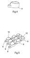
- Fig. 4 shows a print support 9 onto which a shape of the individualized tooth veneer 7 to be produced and the at least one sprue can be printed.
- a number of different shapes of individualized tooth veneers 7 can be printed sequentially by moving the printer relative to a number of print supports 9 to end up with a number of print supports 9, each supporting the printed shape of the individualized tooth veneer 7 to be produced and at least one sprue 8, in wax-like or acrylic material and in three dimensions.
- Fig. 5 shows a result of such a printing process.
- Each print support may have a surface with a shape corresponding to the shape of a surface of the veneer 7, such as the back surface 5 thereof.
- the veneer can also be produced using a milling technology as described in WO 2005/046502 , which is incorporated herein in its entirety by reference for any purpose.
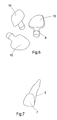
- Fig. 6 shows the shape of the master 10 of the individualized tooth veneer 7 and the part 8 as removed from the print support 9.
- Fig. 7 shows schematically how the shape of the individualized tooth veneer 7 would fit to the pre-determined tooth 3.
- sprue 8 is not shown in Fig. 7 .
- the individualized tooth veneer 7 may be produced using an investment casting technique.
- the master of the individualized tooth veneer 7, as optionally provided with one or more parts 8 corresponding to sprues, commonly also referred to as "the mold" can be placed in a so-called cuvette .
- the mold, as placed in a cuvette is surrounded by an investment material, such as gypsum.
- the material of the mold is burned out from the cuvette so that a cavity is formed for forming the veneer 7, with the ceramic material of which the veneer 7 is to be made.
- the ceramic material is supplied to this cavity through the sprues 8 and pressed into the space under vacuum and at high temperature.
- a veneer 7 has been formed in the desired shape, demolding takes place, for instance by blasting the investment material.
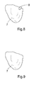
- Fig. 8 shows an example of the veneer 7.
- the part resulting from the sprue can be removed by standard methods, such as polishing or milling.
- the final result, namely the individualized tooth veneer of ceramic material 11, is shown in Fig. 9 .
- the veneer 7 is thus provided in its final shape.
- a method of producing a final shape of an individualized tooth veneer 7 for a predetermined tooth 3 comprises the method of designing for production of a final shape of the individualized tooth veneer 7, as elaborated upon above.
- Each individualized tooth veneer 7 may be tailor-made for a predetermined tooth of a person so that a tailor-made veneer is available for each predetermined tooth of that person.
- the designing may comprise providing on the basis of the three-dimensional representation, computer-readable veneer data for determining the geometry of a master of the plurality of individualized veneers 7 and sprues 8, so that the plurality of individualized veneers can be produced by a single casting or molding cavity that has the geometry of the master.
- a holder 12 is produced for holding each of the individualized tooth veneers 7.
- the holder 12 can also be individualized and be produced on the basis of the computer-readable tooth data. The individualized tooth holder 12 will then be very suitable for holding the individualized tooth veneer in the period beginning after the production of the tooth veneer 7 and ending on placement of the individualized tooth veneer 7 onto the predetermined tooth 3.
- the production of the individualized holder 12 comprises preferably the production of a first part 13 which is provided with a shape for fittingly matching a back surface of the individualized tooth veneer 7.
- the first part 13 may have a shape that is complementary to a shape of the back surface of the individualized tooth veneer 7. The difference may be only the space provided for the bonding material. Hence, the first part 13 may contact substantially the entire back surface 5 of the tooth veneer 7.
- such a first part 13 is provided as comprising a model of a at least a tooth part 12 of a predetermined tooth for which the veneer 7 has been designed and produced.
- Fig. 11a shows a frontal view of such a model.
- Fig. 11b shows a frontal part of an individualized tooth veneer 7 that is intended to cover one of the teeth shown in the model 13.
- the individualized tooth veneer 7 covers in this embodiment one of the front teeth.
- the position of the individualized tooth veneer 7 is indicated by the same reference and is drawn in thick lines.
- the model of the tooth for which the individualized veneer 7 has been designed and produced will most suitably provide the first part 13with a shape for fittingly matching a back surface of the individualized tooth veneer 7.
- the first part 13 is provided with a shape for fittingly matching one side of the tooth veneer 7 in a way different from providing a tooth part for which the veneer 7 has been designed and produced.
- the first part 13 may be produced by CAM technology, such as by rapid prototyping as described above or by milling.
- Holder 12 preferably provides a second part 14 so that the individualized tooth veneer 7 can be sandwiched between the first part 13 and the second part 14.
- the second part 14 is suitable for releasably bonding a front surface of the individualized tooth veneer 7 against the second part 14.
- the second part 14 may be provided as a foil.
- the second part 14 may be provided with a shape for fittingly matching a front surface of the individualized tooth veneer 7.
- the second part may have a shape fittingly matching any of the teeth neighboring the tooth for which the veneer 7 is produced. This facilitates using the second part 14 as a tool to apply the veneer 7 to the tooth for which it is produced.
- first part 13 and second part 14 are provided such that these are releasably securable to each other when the individualized tooth veneer 7 is sandwiched between the first part 13 and the second part 14.
- the second part 14 may be provided with the appropriate shape by providing the foil as made of a plastic. This plastic may be heated. Then the individualized tooth veneer 7 may be sandwiched between the first part 13 and the second part 14, followed by vacuum pressing the foil onto the first part 13.
- an adhesive may be provided to the second part 14. This adhesive may also be suitable for releasably bonding the front surface of the individualized tooth veneer 7 against the second part 14.
- the second part 14 may also be made suitable for releasably bonding the front surface of the individualized tooth veneer and/or releasably securing to the first part 13, by means of electrostatically bonding of a foil to the veneer 7 and/or the first part 13. Such a method is well known in the art, and is often used for providing a foil to a display on, for instance, a new mobile telephone.
- Second part 14 may be a transparent part, as shown in Fig. 12 , 13 and 16 .
- the releasable bonding may be provided by, e.g., vacuum bonding, electrostatic bonding, and/or an adhesive bonding film.
- Vacuum bonding can be provided by a thermo-forming unit, wherein a deformable blank is pre-heated, positioned on top of the first part with the veneer 7 in-between and then deformed by activating a vacuum pump, whereby the blank releasably bonds to the veneer 7, which is supported by the first part 13. Then, the deformed blank can be trimmed to a desired shape.
- a vacuum forming apparatus is available from, e.g., Dreve, Germany, under the tradenames Vacformat U, Vacformat 2000 and Druformat Scan. Bonding films, such as electrostatic foils or films, films with adhesives, both resin based and light curing based, etc. are available, from, e.g., 3M, USA.
- Producing the holder 12 preferably comprises providing the second part 14 with grasp holders 15 for manually holding the second part 14 during placement of the individualized tooth veneer 7 against the predetermined tooth.
- grasp holders 15 may be glued onto the second part 14 or may be provided by means of a mechanical attachment which is possible where the second part has a thickness which allows for instance for screwing on a little screw that forms part of the grasp holder 15.
- a plurality of individualized tooth veneers 7 are produced for a predetermined set of teeth.
- a plurality P of individualized tooth veneers 7 is shown in Fig. 14 .
- the second part 14 is then preferably produced such that the front surface of each of the plurality P of individualized tooth veneers 7 can be releasably bonded against the second part 14 in a fixed positional relationship which corresponds to a positional relationship of the teeth in the predetermined set of teeth 1 for which the veneers 7 are produced.
- Fig. 16 shows such a fixed positional relationship between individualized tooth veneers 7 as releasably bonded against the second part 14.
- a method of improving the aesthetics of a number of predetermined teeth may first comprise the production of the individualized tooth veneers 7 in ways explained above, followed by placing each of these veneers 7 from the first part 13 onto the predetermined tooth.
- Such a method may comprise using the second part 14 as a tool for placing the veneers 7 onto the predetermined teeth. Taking the individualized veneers 7 from the first part 13 can simply be done by lifting the second part 14 from the first part 13 and, if needed, undo the securing of the second part 14 against the first part 13. A result of lifting the second part 14, is shown in Fig. 16 .
- the plurality of individualized tooth veneers is held in the predetermined fixed positional relationship by holding, in this case in the hand, the second part 14.
- the method of producing the individualized tooth veneer and the individualized holder comprises applying a bonding material to the individualized tooth veneer 7. This can be followed by sandwiching the individualized tooth veneer 7 between the first part 13 and the second part 14. Where the individualized tooth veneers 7 are made to be translucent, a coloring agent may be added to the bonding material. After placement of the individualized tooth veneer 7 against the predetermined tooth, the bonding material may be light-hardened in a way well known in the art, for fixing the individualized tooth veneer 7 against the predetermined tooth.
- the tooth veneer 7 is pre-treated with a bonding material before application to a tooth and possibly even before delivery to the dental practitioner who will apply the tooth veneer 7 to the relevant tooth.
- the bonding material is typically applied to the tooth onto which the veneer is to be applied, the veneer is then placed on that tooth, and the bonding material cured, such as by light curing.
- the bonding material is at least partly applied to the tooth veneer 7, such as 25-75% of the total bonding material to be used for bonding the tooth veneer 7.
- the pre-treatment can be carried out at the production facility of the tooth veneer 7 or by a dental technician.
- the pre-treatment of at least one side of the tooth veneer 7, such as the backside facing the tooth may comprise at least one of the following steps: cleaning of the tooth veneer; application of etching gel for preparing a chemical and/or mechanical connection surface; providing etched surface prepared for sealing with silane as transport protection; applying a silanization process for obtaining a silanized surface; application of at least one layer of bonding material on top of the silanized surface; application of coloring material, such as for cervical and/or incisal colorings, before, on top of, or mixed in the bonding material; applying the bonding material to the tooth veneer 7; and light curing the bonding material for delivery to the dental practitioner.
- Embodiments may also comprise pre-treatment by the practitioner of the tooth to receive the tooth veneer.
- the pre-treatment by the practitioner may comprise at least one of the following steps: cleaning the non-prepared (i.e. substantially non-ground front surface) surface of the tooth, such as with isopropanol; etching of the tooth surface, such as with etching gel, e.g. fluoride etching gel, fluoride hydrogen etching gel etc.; silanization of the etched tooth surface; and application of the remainder of the binding material, such as 25%-75 if 25-75% was applied to the tooth veneer 7 and to end up at total of 100%, onto the tooth surface.
- the bonding material applied to the tooth surface may have a neutral color, such as transparent or white, whereby appearance provided by the coloring added to the veneer is substantially not affected.
- Embodiments of the invention may also comprise at least one of the following steps for a veneering procedure: providing pre-treated veneer 7 with hardened bonding material; applying the tooth veneer onto the tooth surface comprising bonding material; adjusting the veneer 7; and curing, such as by light curing, the connection between the surfaces with bonding material.
- the veneer 7 may comprise a pre-treated bonding material.
- the pre-treated bonding material may comprise an at least partially cured bonding material, such as a light curable dental bonding agent.
- the pre-treated bonding material may comprise at least one coloring material to color the veneer 7. Hence, due to the thinness of the veneer 7 in combination with its translucency the coloring of the bonding material will be visible. Therefore, application of a separate coloring layer is not necessary.
- the bonding material may be applied by a CAM procedure, such as by ink-jet technology.
- the CAD user interface can provide means to design different layers of the bonding material and/or different areas of the tooth veneer having different shades of the bonding material. For example, a suggestion may be automatically generated based on the type of tooth, such as front or incisor, onto which the veneer 7 is to be applied.
- the user indicates, such as by indicating with the cursor, areas defined by lines defining a closed curve. Within the border of the lines a particular color of the bonding material is defined and subsequently applied.
- a pattern having different areas corresponding to the tooth anatomy may be projected onto the three dimensional representation of the individual tooth veneer.
- the user can select a particular color for a particular area.
- Application of the bonding material may be provided using the technology as described in WO2006/036114 , which is incorporated herein by reference in its entirety for any purpose, for applying a metal and/or ceramic powder, but does not disclose application of a bonding material.
- the bonding material may also be applied manually as described above.
- Routine procedures may alternatively be carried out by the dental practitioner before applying the individualized tooth veneer 7 to the predetermined tooth.
- the surface of the tooth that is to be covered by the veneer 7 may be etched in order to provide a clean surface.
- the etching may be followed by applying a silanization layer as part of a routine and standard procedure carried out by a dental practitioner.
- the silanization layer provides a sealing to the etched surface.
- the ceramic material may be a glass ceramic material , such as a Li-disilicate glass ceramic.
- Li-disilicate glass ceramic has a high strength, which provides for improved possibilities to handle the fragile product.
- Such glass-ceramic is e.g. available under the tradename IPS e.max from Ivoclar Vivadent, Lichtenstein.
- the ceramic material may comprise a microwave sintered aluminium oxide ceramic.
- the veneer 7 comprises a single layer of glass-ceramic having uniform composition.
- non-ceramic coloring and/or glazing layers may be added at least on one side of the veneer 7.
Priority Applications (4)
| Application Number | Priority Date | Filing Date | Title |
|---|---|---|---|
| EP09008945A EP2272462A1 (fr) | 2009-07-09 | 2009-07-09 | Procédé de production d'une facette dentaire individualisée et support |
| JP2012518826A JP2012531989A (ja) | 2009-07-09 | 2010-07-08 | 個別化された歯被覆及び保持器を製造する方法 |
| US13/382,865 US20120175799A1 (en) | 2009-07-09 | 2010-07-08 | Method of producing an individualized tooth veneer and a holder |
| PCT/EP2010/004171 WO2011003612A1 (fr) | 2009-07-09 | 2010-07-08 | Procédé de production d'un facette prothétique individuelle et d'un support |
Applications Claiming Priority (1)
| Application Number | Priority Date | Filing Date | Title |
|---|---|---|---|
| EP09008945A EP2272462A1 (fr) | 2009-07-09 | 2009-07-09 | Procédé de production d'une facette dentaire individualisée et support |
Publications (1)
| Publication Number | Publication Date |
|---|---|
| EP2272462A1 true EP2272462A1 (fr) | 2011-01-12 |
Family
ID=41397576
Family Applications (1)
| Application Number | Title | Priority Date | Filing Date |
|---|---|---|---|
| EP09008945A Withdrawn EP2272462A1 (fr) | 2009-07-09 | 2009-07-09 | Procédé de production d'une facette dentaire individualisée et support |
Country Status (4)
| Country | Link |
|---|---|
| US (1) | US20120175799A1 (fr) |
| EP (1) | EP2272462A1 (fr) |
| JP (1) | JP2012531989A (fr) |
| WO (1) | WO2011003612A1 (fr) |
Cited By (6)
| Publication number | Priority date | Publication date | Assignee | Title |
|---|---|---|---|---|
| US20150257853A1 (en) | 2009-02-02 | 2015-09-17 | Viax Dental Technologies, LLC | Dentist tool |
| EP2637597B1 (fr) * | 2010-11-09 | 2018-03-14 | 3M Innovative Properties Company | Procédé de fabrication d'article dentaire, article pouvant être obtenu par ce procédé et ses utilisations |
| US10144100B2 (en) | 2009-02-02 | 2018-12-04 | Viax Dental Technologies, LLC | Method of preparation for restoring tooth structure |
| US10426572B2 (en) | 2011-05-26 | 2019-10-01 | Viax Dental Technologies Llc | Dental tool and guidance devices |
| US11007035B2 (en) | 2017-03-16 | 2021-05-18 | Viax Dental Technologies Llc | System for preparing teeth for the placement of veneers |
| USD982761S1 (en) | 2021-05-13 | 2023-04-04 | Viax Dental Technologies Llc | Dental restoration placement tray |
Families Citing this family (5)
| Publication number | Priority date | Publication date | Assignee | Title |
|---|---|---|---|---|
| KR101913589B1 (ko) | 2017-06-01 | 2018-10-31 | 진순환 | 라미네이트 보철물의 제조방법 |
| KR102065069B1 (ko) * | 2018-05-09 | 2020-01-10 | 이승희 | 3d 프린터를 이용한 치아수복물 제작 장치 및 방법 |
| KR102066669B1 (ko) | 2018-09-05 | 2020-01-15 | 홍동은 | 3d 프린터를 이용하는 유치관 제조방법 및 이를 통해 제작된 유치관 및 삼각형 형상으로 제작된 유치관 |
| CN112587257B (zh) * | 2019-09-17 | 2022-07-19 | 胡可辉 | 一种义齿贴面的制备方法及由此制备的义齿贴面 |
| US11925524B1 (en) | 2023-06-07 | 2024-03-12 | King Faisal University | Dental tooth grasper |
Citations (8)
| Publication number | Priority date | Publication date | Assignee | Title |
|---|---|---|---|---|
| WO1994027523A1 (fr) * | 1993-05-21 | 1994-12-08 | Tritech Mekatronik Ab | Methode et dispositif de restauration dentaire |
| WO2005046502A1 (fr) | 2003-11-12 | 2005-05-26 | Nobel Biocare Ab (Publ) | Systeme et dispositif pour fabriquer un composant de remplacement dentaire et composant de remplacement dentaire |
| US20050227204A1 (en) | 2004-04-12 | 2005-10-13 | Hauck Douglas J | Daily wear temporary dental veneers |
| WO2006021240A1 (fr) * | 2004-08-25 | 2006-03-02 | Remedent Nv | Protheses dentaires |
| WO2006036114A1 (fr) | 2004-09-30 | 2006-04-06 | Nobel Biocare Services Ag | Procede et systeme pour colorer ou teindre une prothese, et prothese associee |
| US20070298381A1 (en) | 2006-06-02 | 2007-12-27 | Gaia Via, Llc | Dental product for temporary teeth coloring and coverage |
| WO2008051130A1 (fr) | 2006-10-27 | 2008-05-02 | Nobel Biocare Services Ag | Procédé et appareil pour obtenir des données d'un composant dentaire et d'un modèle dentaire physique |
| US20090004629A1 (en) | 2007-06-26 | 2009-01-01 | Laurence Fishman | Aesthetic dental arch laminates and adhesive |
Family Cites Families (4)
| Publication number | Priority date | Publication date | Assignee | Title |
|---|---|---|---|---|
| US4226593A (en) * | 1979-04-16 | 1980-10-07 | Morton Cohen | Apparatus and method for applying dental veneer |
| EP0827941B1 (fr) * | 1996-09-05 | 1999-11-03 | Ivoclar Ag | Vitrocéramique de disilicate de lithium frittable |
| US6182820B1 (en) * | 1998-10-30 | 2001-02-06 | John F. Rathbauer | Veneer holder |
| JP2006034662A (ja) * | 2004-07-28 | 2006-02-09 | Teeth & Smile | 歯用装飾品の収納及び取付用品、並びに、歯用装飾品の取付け方法 |
-
2009
- 2009-07-09 EP EP09008945A patent/EP2272462A1/fr not_active Withdrawn
-
2010
- 2010-07-08 JP JP2012518826A patent/JP2012531989A/ja active Pending
- 2010-07-08 US US13/382,865 patent/US20120175799A1/en not_active Abandoned
- 2010-07-08 WO PCT/EP2010/004171 patent/WO2011003612A1/fr active Application Filing
Patent Citations (8)
| Publication number | Priority date | Publication date | Assignee | Title |
|---|---|---|---|---|
| WO1994027523A1 (fr) * | 1993-05-21 | 1994-12-08 | Tritech Mekatronik Ab | Methode et dispositif de restauration dentaire |
| WO2005046502A1 (fr) | 2003-11-12 | 2005-05-26 | Nobel Biocare Ab (Publ) | Systeme et dispositif pour fabriquer un composant de remplacement dentaire et composant de remplacement dentaire |
| US20050227204A1 (en) | 2004-04-12 | 2005-10-13 | Hauck Douglas J | Daily wear temporary dental veneers |
| WO2006021240A1 (fr) * | 2004-08-25 | 2006-03-02 | Remedent Nv | Protheses dentaires |
| WO2006036114A1 (fr) | 2004-09-30 | 2006-04-06 | Nobel Biocare Services Ag | Procede et systeme pour colorer ou teindre une prothese, et prothese associee |
| US20070298381A1 (en) | 2006-06-02 | 2007-12-27 | Gaia Via, Llc | Dental product for temporary teeth coloring and coverage |
| WO2008051130A1 (fr) | 2006-10-27 | 2008-05-02 | Nobel Biocare Services Ag | Procédé et appareil pour obtenir des données d'un composant dentaire et d'un modèle dentaire physique |
| US20090004629A1 (en) | 2007-06-26 | 2009-01-01 | Laurence Fishman | Aesthetic dental arch laminates and adhesive |
Cited By (12)
| Publication number | Priority date | Publication date | Assignee | Title |
|---|---|---|---|---|
| US20150257853A1 (en) | 2009-02-02 | 2015-09-17 | Viax Dental Technologies, LLC | Dentist tool |
| US10144100B2 (en) | 2009-02-02 | 2018-12-04 | Viax Dental Technologies, LLC | Method of preparation for restoring tooth structure |
| US10441382B2 (en) | 2009-02-02 | 2019-10-15 | Viax Dental Technologies, LLC | Dentist tool |
| US11253961B2 (en) | 2009-02-02 | 2022-02-22 | Viax Dental Technologies Llc | Method for restoring a tooth |
| US11813127B2 (en) | 2009-02-02 | 2023-11-14 | Viax Dental Technologies Llc | Tooth restoration system |
| US11865653B2 (en) | 2009-02-02 | 2024-01-09 | Viax Dental Technologies Llc | Method for producing a dentist tool |
| EP2637597B1 (fr) * | 2010-11-09 | 2018-03-14 | 3M Innovative Properties Company | Procédé de fabrication d'article dentaire, article pouvant être obtenu par ce procédé et ses utilisations |
| US10426572B2 (en) | 2011-05-26 | 2019-10-01 | Viax Dental Technologies Llc | Dental tool and guidance devices |
| US11033356B2 (en) | 2011-05-26 | 2021-06-15 | Cyrus Tahmasebi | Dental tool and guidance devices |
| US11925517B2 (en) | 2011-05-26 | 2024-03-12 | Viax Dental Technologies Llc | Dental tool and guidance devices |
| US11007035B2 (en) | 2017-03-16 | 2021-05-18 | Viax Dental Technologies Llc | System for preparing teeth for the placement of veneers |
| USD982761S1 (en) | 2021-05-13 | 2023-04-04 | Viax Dental Technologies Llc | Dental restoration placement tray |
Also Published As
| Publication number | Publication date |
|---|---|
| JP2012531989A (ja) | 2012-12-13 |
| WO2011003612A1 (fr) | 2011-01-13 |
| US20120175799A1 (en) | 2012-07-12 |
Similar Documents
| Publication | Publication Date | Title |
|---|---|---|
| EP2272462A1 (fr) | Procédé de production d'une facette dentaire individualisée et support | |
| US11298216B2 (en) | System and method for manufacturing layered dentures | |
| EP3135243B1 (fr) | Prothèse dentaire en couches | |
| US20120183921A1 (en) | Dental product comprising at least one veneer | |
| US20060008777A1 (en) | System and mehtod for making sequentially layered dental restoration | |
| US9687326B2 (en) | Process for making a dental restoration and resultant apparatus | |
| AU2014202799B2 (en) | Method for producing a denture | |
| EP2237737A1 (fr) | Processus permettant d'exécuter une restauration dentaire et appareil associé | |
| CN112294483B (zh) | 贴面修复体比色板系统及其制作方法 | |
| US20110117524A1 (en) | Universal dental crown and system and method of restoring a tooth using a universal dental crown | |
| US20130330690A1 (en) | Dental veneer product | |
| US8377500B2 (en) | Process for making a dental restoration and resultant apparatus | |
| JP2012531987A (ja) | 歯科製品、及び歯科製品の輸送のための保持システムの組立て体 | |
| JP2007236465A (ja) | 多層人工歯用本体部材 | |
| CN205359664U (zh) | 使用复合树脂材料在牙齿上形成贴面的模板及其形成工具 | |
| WO2012095297A1 (fr) | Produit de facette dentaire | |
| JP6301210B2 (ja) | 有床義歯の製造方法および有床義歯 | |
| Abdul-Rahman | Abd-Alhameed Hassan Gillab | |
| EP1970023A1 (fr) | Revêtement pour couronne dentaire modulaire | |
| US20070117067A1 (en) | Modular tooth veneer | |
| Kahng | Proper Restorative Material Selection, Digital Processes Allow Highly Esthetic Shade Match Combined with Layered Porcelain. | |
| WO2012141703A1 (fr) | Couronne dentaire universelle et système et procédé de restauration d'une dent utilisant une couronne dentaire universelle |
Legal Events
| Date | Code | Title | Description |
|---|---|---|---|
| PUAI | Public reference made under article 153(3) epc to a published international application that has entered the european phase |
Free format text: ORIGINAL CODE: 0009012 |
|
| AK | Designated contracting states |
Kind code of ref document: A1 Designated state(s): AT BE BG CH CY CZ DE DK EE ES FI FR GB GR HR HU IE IS IT LI LT LU LV MC MK MT NL NO PL PT RO SE SI SK SM TR |
|
| AX | Request for extension of the european patent |
Extension state: AL BA RS |
|
| 17P | Request for examination filed |
Effective date: 20110712 |
|
| 17Q | First examination report despatched |
Effective date: 20110802 |
|
| STAA | Information on the status of an ep patent application or granted ep patent |
Free format text: STATUS: THE APPLICATION IS DEEMED TO BE WITHDRAWN |
|
| 18D | Application deemed to be withdrawn |
Effective date: 20140415 |