EP2271876B1 - Dispositif de brûleur pour combustibles fluides et procédé de fabrication du dispositif de brûleur - Google Patents
Dispositif de brûleur pour combustibles fluides et procédé de fabrication du dispositif de brûleur Download PDFInfo
- Publication number
- EP2271876B1 EP2271876B1 EP09764490A EP09764490A EP2271876B1 EP 2271876 B1 EP2271876 B1 EP 2271876B1 EP 09764490 A EP09764490 A EP 09764490A EP 09764490 A EP09764490 A EP 09764490A EP 2271876 B1 EP2271876 B1 EP 2271876B1
- Authority
- EP
- European Patent Office
- Prior art keywords
- burner
- hub
- fuel supply
- fuel
- supply duct
- Prior art date
- Legal status (The legal status is an assumption and is not a legal conclusion. Google has not performed a legal analysis and makes no representation as to the accuracy of the status listed.)
- Not-in-force
Links
Images


Classifications
-
- F—MECHANICAL ENGINEERING; LIGHTING; HEATING; WEAPONS; BLASTING
- F23—COMBUSTION APPARATUS; COMBUSTION PROCESSES
- F23R—GENERATING COMBUSTION PRODUCTS OF HIGH PRESSURE OR HIGH VELOCITY, e.g. GAS-TURBINE COMBUSTION CHAMBERS
- F23R3/00—Continuous combustion chambers using liquid or gaseous fuel
- F23R3/28—Continuous combustion chambers using liquid or gaseous fuel characterised by the fuel supply
- F23R3/283—Attaching or cooling of fuel injecting means including supports for fuel injectors, stems, or lances
-
- F—MECHANICAL ENGINEERING; LIGHTING; HEATING; WEAPONS; BLASTING
- F23—COMBUSTION APPARATUS; COMBUSTION PROCESSES
- F23D—BURNERS
- F23D2211/00—Thermal dilatation prevention or compensation
-
- F—MECHANICAL ENGINEERING; LIGHTING; HEATING; WEAPONS; BLASTING
- F23—COMBUSTION APPARATUS; COMBUSTION PROCESSES
- F23D—BURNERS
- F23D2900/00—Special features of, or arrangements for burners using fluid fuels or solid fuels suspended in a carrier gas
- F23D2900/00018—Means for protecting parts of the burner, e.g. ceramic lining outside of the flame tube
Definitions
- the invention relates to a burner assembly for fluid fuels and a method of manufacturing a burner assembly.
- Gas turbine engines are used in power plants and other large-scale engine applications, among other things, with burner assemblies for firing fluid fuels.
- burner assemblies for firing fluid fuels.
- so-called dual-fuel burners are used, which are provided for the combustion of liquid and gaseous fuels, for example natural gas and fuel oil, optionally or in combination.
- the burner assemblies are accordingly large in size and have a complex structure with multiple fuel supply channels.
- a centrally located small sized pilot burner with its own fuel supply and air supply is used to stabilize the flame of a large main burner which is placed around the pilot burner.
- the large main burner is operated predominantly in lean-mixed operation with excess oxygen, thereby achieving more favorable emission values.
- operation with a lean mixture causes the flame of the main burner at least in certain operating conditions subject to fluctuations, which are compensated by a continuous firing action of the pilot burner.
- Such a burner arrangement is for example in EP 0 580 683 B1 played.
- the so-called hub in which the Zubigringkanäle the gas and oil fuels are arranged relatively close together, represents a gas ring space feeds the main burner based upstream of the so-called swirl vanes, which impart a mixing swirl to the air stream with the fuel gas, or through the swirl vanes, on the upstream side of the flow direction of the incoming air.
- an oil supply is present, which is usually located closer to the burner outlet, as the gas supply. It comprises an oil annulus and a leading to the annulus oil supply channel, which is located in the located between the gas annulus and the pilot burner hub wall.
- gas Since gas has a lower density compared to oil, it requires a larger cross-section, whereby the dimensioning of the gas supply is much greater than the oil supply. Therefore, the part of the burner hub with the gas supply to a larger air duct facing outer surface than the oil supply.
- the air supply is done with pre-compressed air that has passed through a compressor, whereby this supplied air due to the compression has a temperature that already reaches over 400 ° C. Consequently, the area of the burner hub with the gas supply is heated rapidly to a temperature in the range of over 400 ° C and remains at this operating temperature.
- the leading to the oil annulus oil supply channel is further away from the hot air supply channel so that the oil in the oil supply channel hardly undergoes heating and therefore only has a temperature of about 50 ° C.
- the present invention therefore has the object to reduce the described thermal stresses in the burner hub of the burner assembly.
- a burner arrangement according to the invention for a firing system for firing fluid fuels comprises a burner hub, an air supply system surrounding the burner hub and at least one fuel supply channel with fuel outlet openings leading in the direction of the air supply system.
- the at least one fuel supply channel is at least partially formed in the burner hub, so that the material of the burner hub forms a wall of the fuel supply channel.
- Disposed in at least one fuel supply passageway is a shielding wall spaced from the wall of the fuel supply passageway so that a gap not belonging to the flow path of the fuel flowing through the fuel supply passageway is formed between the wall of the fuel supply passageway and the shielding wall.
- the shielding wall is formed as a introduced into the fuel supply passage, adapted to the inner contour of the fuel supply channel hollow body.
- the gap forms a poorly heat-conducting region in comparison to the surrounding metal of the burner hub, which thermally insulates the metal of the hub from the flowing fuel and thus limits the heat exchange between the fuel and the burner hub. Due to the reduced heat exchange, the thermally induced stresses decrease in comparison to burner arrangements without shielding wall.
- the adaptation to the inner contour of the fuel supply channel allows it is to ensure a uniform space between the wall of the fuel supply channel and the shield.
- the fuel supply channel may in particular comprise a distribution channel leading to the fuel outlet openings and a substantially annular distribution channel and a substantially tubular supply channel leading to the distribution channel.
- the hollow body for example, is designed as a sleeve or as a hollow torus.
- the hollow body is preferably formed at least partially of metal or ceramic.
- the hollow body can in principle be formed in one piece or in several parts.
- a formed of metal hollow body may, for example, at least partially as a bent sheet metal part or at least partially as a machined metal part, such as a rotating part, be formed.
- the hollow body may be provided with outlet projections which are inserted into the respective fuel outlet openings of the fuel supply channel, so that penetration of fuel into the intermediate space at the transition between the distributor channel and the fuel outlet openings can be avoided.
- the hollow body may be provided with at least one inlet port which is inserted into an inlet opening of the fuel supply channel to prevent penetration of fuel into the gap at the transition between the supply channel and the distribution channel.
- the projections may also serve as positioning means which hold the hollow body in the fuel channel in the correct position.
- the fuel supply channel comprises a arranged in the wall of the burner hub, leading to the fuel outlet openings and at least partially ring-shaped fuel distribution channel. This is formed from two with the open sides opposite each other arranged grooves.
- the burner hub comprises at least a first and a second hub part, which are joined together. A parting plane between the first and the second hub part extends through the fuel distributor passage of the respective fuel supply passage such that one of the grooves forming the fuel distributor passage is present in each hub part before the two hub parts are assembled and the hollow body can be positioned in one of the grooves.
- the first and the second hub part and possibly further hub parts of the burner hub may be connected to one another by force, form or material, for example by welding, soldering, screwing or riveting.
- the method according to the invention makes it possible to produce a burner hub with a shielding wall in an annular fuel distributor channel, wherein the shielding wall is designed as a hollow body introduced into the fuel distributor channel.
- the method can in particular also be applied to a burner hub with more than two hub parts.
- a further hollow body is installed in the groove forming part of a fuel supply channel in a further hub part of the burner hub.
- the hub parts are joined together and created a force, positive or cohesive connection between the assembled hub parts of the burner hub.
- FIG. 1 shows a burner assembly according to the prior art, which may optionally be used in conjunction with a plurality of similar arrangements, for example in the combustion chamber of a gas turbine plant.
- the pilot burner system comprises a central oil feed 1 (medium G) with an oil nozzle 5 arranged at its end and an inner gas supply channel 2 (medium F) arranged concentrically around the central oil feed 1. This in turn is surrounded by a concentrically arranged around the axis of the burner inner air supply channel 3 (Medium E).
- a suitable ignition system may be arranged, for which many possible embodiments are known and its representation has therefore been omitted here.
- the inner air supply channel 3 has a swirl blading 6 in its end region.
- the pilot burner system can operate in a manner known per se, i. H. predominantly as a diffusion burner operated. Its task is to maintain the main burner in a stable burning operation, since it is usually operated with a lean mixture to reduce the emission of pollutants, which requires stabilizing its flame by means of a diffusion flame or based on a less lean mixture flame.
- the main burner system has a concentric with the pilot burner system arranged and obliquely on this incoming outer air supply annular duct system 4.
- This air supply annular channel system 4 is also provided with a swirl blading 7.
- the swirl blading 7 consists of hollow blades with outlet nozzles 11 in the flow cross-section of the air supply annular channel system 4 (medium A). These are fed from a gas feed channel 19 and a gas ring channel 9 through openings 10.
- the burner has an oil feed channel 23, which opens into an oil ring channel 13, which in turn has outlet nozzles 14 in the region or downstream of the swirl blading 7.
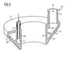
- FIG. 2 shows an embodiment of the burner hub 18 of a burner assembly according to the prior art in cross section.
- a gas annulus 9 and an oil annulus 13 are arranged.
- the annular spaces 9 and 13 each have a plurality of outlet openings 10 and 14, through which the respective fuel (medium B or medium C in FIG. 1 ) can escape.
- FIG. 3 is a schematically exaggerated sequence of thermally induced stresses in the burner hub of the prior art FIG. 2 shown. Due to the stresses, the wall 21 between the gas annulus 9 and the oil supply passage 23 is deformed. This deformation of the metallic burner hub 18 is due to the temperature gradient in the wall between the oil feed channel 23, flows through the oil at a temperature of about 50 ° C, and the gas annulus 9, due to the heating by the compressor air in the air supply channel. 4 (Medium A in Fig.1 ) is heated to about 420 ° C.
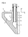
- FIG. 4 shows a detail of a cross section through an embodiment of the burner assembly according to the invention.
- the burner assembly comprises a burner hub 18, in which a gas annulus 9 with a gas supply channel 19 (in FIG. 4 not shown) and an oil annulus 13 are arranged with an oil supply passage 23.
- the basic structure of the burner assembly corresponds to that with reference to the FIGS. 1 and 2 described structure. It will therefore only the differences to the FIGS. 1 and 2 described burner structure described.
- a shielding wall 30 is arranged in the oil supply duct 23 such that a gap 38 is formed between the wall 21 between the gas ring space 9 and the oil supply duct 23 on the one hand and the shield wall 30 on the other hand.
- This space 38 isolates the one formed by the inner surface of the shield 30 Flow path of the oil thermally from the wall 21 between the gas annulus 9 and the oil supply passage 23, since the medium in the gap, such as air or no or hardly flowing oil, has a much lower thermal conductivity than the metal of the burner hub 18th
- the thermal conductivity of air is 0.023 W / mK and that of oil is about 0.15 W / mK (at room temperature).
- the gap 38 can therefore be considered as an adiabatic thermal shield.
- the amount of the distance s between the wall 21 and the shielding wall 30 may be used constructively to set a desired heat transfer rate.
- the shielding wall is realized in the form of a sleeve 30 inserted into the oil feed duct 23, which prevents direct contact of the cold oil flowing along the flow path in the oil feed duct 23 with the wall 21 between the gas annular space 9 and the oil feed duct 23.
- the outer diameter of the sleeve 30 is dimensioned smaller by a predetermined amount than the inner diameter of the oil feed channel 23, so that between the inserted sleeve 30 and the wall 21, a gap 38 is formed, in which a medium having a substantially lower thermal conductivity than the metal Burner hub 18 is located.
- the oil itself can be used in the simplest case, provided that no ignition is to be feared, since in this case no sealing of the intermediate space 38 against the flow path of the oil is required.
- the sleeve 30 In order to easily mount the sleeve 30 in the oil supply passage 23 of the burner hub 18, it is designed as a insertable into an opening in a tubular section 37 of the oil supply passage 23 sleeve 30.
- the sleeve 30 has for this purpose at its upstream end a preferably circular, annular positioning projection 33 which serves as a spacer for radially centering the sleeve body in the oil supply passage 23 and at the same time carries the function of a abutting edge, against a complementary, in the region of the opening the tubular projection 37 abuts existing abutment edge of a corresponding Nutausfräsung and thus determines the position of the sleeve 30 in the axial direction.
- the present embodiment has a further positioning projection 35, which is arranged in the vicinity of the downstream end of the sleeve 30.
- a further positioning projection 35 is arranged in the vicinity of the downstream end of the sleeve 30.
- positioning projection 35 is preferably designed as an annular nikum Surpriseder projection and extends with its preferably cylindrically configured outer diameter up to the wall of the cavity 38 so that it also contributes to the centering of the sleeve 30.
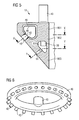
- FIG. 5 shows a second embodiment of the burner hub 18 according to the invention with a arranged in the gas annulus 9 shielding, which is formed by a hollow body 40 inserted into the gas annulus 9.
- this is modeled on the ring shape of the annular space 9 and thereby formed itself toroidal.
- FIG. 6 is a perspective view of the toroidal Hol stressess 40 shown.
- the outer dimensions of the toroidal hollow body 40 are selected with respect to the inner dimensions of the gas annular space 9 such that an adiabatically acting gap 48 is formed between the outer side of the hollow body 40 and the inner surface of the gas ring space 9, with which the incoming fuel gas from the walls of the gas annulus. 9 is thermally isolated.
- the toroidal hollow body 40 has a plurality of circumferentially arranged outlet ports 42. As in FIG. 5 can be seen, they are introduced into the fuel outlet openings 10 of the gas annulus 9 so that their outer surfaces abut the inner surfaces of the openings 10.
- the toroidal hollow body 40 has at least one inlet connection 43 which can be introduced into the gas supply duct 19 leading to the gas annular space 9 such that its outer surface rests against the inner surfaces of the gas supply duct 19.
- These ports 42 and 43 also perform the function of spacers, through which between the walls of the gas annulus 9 and the outer surfaces of the sheath device 40 is set a predetermined state and maintained during operation.
- the gas flowing through is prevented from direct heat exchange with the surrounding areas of the burner hub 18.
- the fuel gas may have a lower temperature than the burner hub 18 heated to about 420 ° C by the pre-compressed air.
- the gas due to the thermal insulation the walls of the annular space 9 does not cool directly.
- the burner hub 18 can achieve a more uniform heating, so that no or only significantly lower thermally induced voltages occur.
- the recessed adiabatically acting gap 48 if no ignition is to be feared, be filled in the simplest case with the gas, which can avoid sealing problems.
- Fuel gases have low thermal conductivity compared to the metal of the burner hub, whereby the heat transfer from the hub wall to the gas is significantly reduced.
- the holharmome 40 is preferably designed as a thin-walled, bent sheet metal component.
- two bent to half-shells sheet metal parts can be assembled and welded or pressed.
- the holody may also be formed as a casting, but the wall thickness caused by casting would be detrimental and would require an increase in the dimensions of the burner hub 18.
- FIG. 5 is also the arranged in the oil supply passage 23 sleeve 30 visible, which projects into the oil annulus 13.
- a shielding wall in the form of a toroidal hollow body corresponding to the holanalysis 40 may be arranged in the gas annulus 9 in the oil annulus 13, so that the heat transfer between the walls of the oil annulus 13 and the oil can also be reduced.
- This donut-shaped hollow body, not shown, can then be connected to the end of the sleeve 30.
- the burner hub 18 is preferably formed in at least two hub parts 1801 and 1802 separated so that the separation plane XX the gas annulus 9 separates substantially symmetrical and circulatory and makes it accessible.
- the gas annulus 9 is then formed essentially of two in the abutment surfaces of the hub parts 1801 and 1802 opposing grooves.
- the toroidal hollow body 40 can be inserted into the groove of one of the two hub parts 1801 and 1802 and fixed there before the two hub parts 1801 and 1802 are joined together.
- the joining of the hub parts 1801 and 1802 can thereafter force, form or cohesive, preferably by welding, riveting or screwing done.
- the burner hub 18 can have a further division along the separating surface Y-Y for this purpose.
- the burner hub 18 in this case comprises a third hub portion 1803, which is separated from the previously arranged hub portion 1802 by the parting plane Y-Y, which separates the oil annulus 13 substantially symmetrical and circular.
- the oil annulus 13 is then also formed essentially of two in the abutting surfaces of the hub parts 1802 and 1803 opposite each other grooves.
- the installation of the toroidal hollow body can be done by the toroidal hollow body 1802 and 1803 inserted before the joining of the two hub parts in the groove of one of the two hub parts 1802 and 1804 and fixed there.
- the sheath device 40 can also be fastened to the inlet connection 43 on the end of the sleeve 30 projecting into the oil annulus.
Landscapes
- Engineering & Computer Science (AREA)
- Chemical & Material Sciences (AREA)
- Combustion & Propulsion (AREA)
- Mechanical Engineering (AREA)
- General Engineering & Computer Science (AREA)
- Nozzles For Spraying Of Liquid Fuel (AREA)
- Gas Burners (AREA)
Claims (13)
- Dispositif ( 20 ) de brûleur pour une installation de combustion de fluide, dans lequel il y a :- un moyeu-brûleur ( 18 ),- un système ( 3, 4 ) d'apport d'air entourant le moyeu-brûleur ;- au moins un canal ( 9, 13, 19, 23 ) d'apport de combustible ayant des ouvertures ( 10, 14 ) de sortie du combustible, tourné dans la direction du système d'apport d'air, le au moins un canal ( 9, 13, 19, 23 ) d'apport de combustible étant constitué au moins en partie dans le moyeu-brûleur ( 18 ) de manière à ce que le matériau du moyeu-brûleur forme une paroi du canal ( 9, 13, 19, 23 ) d'apport de combustible,caractérisé en ce que- dans au moins un canal ( 9, 13, 19, 23 ) d'apport de combustible est disposée une paroi ( 30, 40 ) formant écran qui est à distance de la paroi ( 21 ) du canal ( 9, 13, 19, 23 ) d'apport de combustible de manière à former, entre la paroi ( 21 ) du canal ( 9, 13, 19, 23 ) d'apport de combustible et la paroi ( 30, 40 ) formant écran, un espace ( 38, 48 ) intermédiaire n'appartenant pas au trajet d'écoulement du combustible passant dans le canal ( 9, 13, 19, 23 ) d'apport de combustible et la paroi ( 30, 40 ) formant écran est constituée sous la forme d'une pièce ( 30, 40 ) creuse introduite dans le canal ( 9, 13, 19, 23 ) d'apport de combustible et adaptée au contour intérieur du canal ( 9, 13, 19, 23 ) d'apport de combustible.
- Dispositif de brûleur suivant la revendication 1,
caractérisé en ce que
le canal ( 9, 13, 19, 23 ) d'apport de combustible comprend un canal ( 9, 13 ) répartiteur menant aux ouvertures ( 10, 14 ) de sortie du combustible et sensiblement annulaire et un canal ( 19, 23 ) d'alimentation sensiblement tubulaire et menant au canal ( 9, 13 ) répartiteur. - Dispositif de brûleur suivant la revendication 1 et la revendication 2,
caractérisé en ce que
la pièce ( 30, 40 ) creuse est constituée sous la forme d'un manchon ( 30 ) ou d'un tore ( 40 ) creux. - Dispositif de brûleur suivant l'une des revendications précédentes,
caractérisé en ce que
la pièce ( 30, 40 ) creuse est, au moins en partie, en métal ou en céramique. - Dispositif de brûleur suivant la revendication 4,
caractérisé en ce que
la pièce ( 30, 40 ) creuse est, au moins en partie, sous la forme d'une pièce de tôle courbée. - Dispositif de brûleur suivant la revendication 4,
caractérisé en ce que
la pièce ( 30, 40 ) creuse est au moins en partie sous la forme d'une pièce métallique formée avec enlèvement de copeaux. - Dispositif de brûleur suivant l'une des revendications précédentes,
caractérisé en ce que
la pièce ( 40 ) creuse est pourvue de raccords ( 42 ) de sortie qui sont introduits dans les ouvertures ( 10 ) respectives de sortie du combustible du canal ( 9 ) d'apport de combustible. - Dispositif de brûleur suivant l'une des revendications précédentes,
caractérisé en ce que
la pièce ( 40 ) creuse est pourvue d'au moins un raccord ( 43 ) d'entrée qui est introduit dans une ouverture d'entrée du canal ( 9, 13 ) d'apport de combustible. - Dispositif de brûleur suivant l'une des revendications précédentes,
caractérisé en ce que- le canal ( 9, 13, 19, 23 ) d'apport de combustible comprend un canal ( 9, 13 ) répartiteur de combustible disposé dans la paroi du moyeu-brûleur ( 18 ) menant aux ouvertures ( 10, 14 ) de sortie du combustible et constituée, au moins en partie annulairement, le canal ( 9, 13 ) répartiteur de combustible étant formé de deux rainures qui sont opposées l'une à l'autre par le côté ouvert,- le moyeu-brûleur ( 18 ) a, au moins, une première et une deuxième parties ( 1801, 1802, 1803 ) de moyeu, qui sont jointes l'une à l'autre et- un plan ( X-X, Y-Y ) de séparation entre la première et la deuxième parties ( 1801, 1802, 1803 ) de moyeu s'étend, dans le canal ( 9, 13, 19, 23 ) répartiteur de combustible du canal ( 9, 13, 19, 23 ) d'apport de combustible respectif de manière à ce que, avant la jonction des deux parties ( 1801, 1802, 1803 ) de moyeu, il y a dans chaque partie ( 1801, 1802, 1803 ) de moyeu respectivement une rainure formant le canal ( 9, 13 ) répartiteur de combustible et la pièce ( 40 ) creuse peut être mise en position dans l'une des rainures. - Dispositif de brûleur suivant la revendication 9,
caractérisé en ce que
la première et la deuxième parties ( 1801, 1802, 1803 ) du moyeu-brûleur ( 18 ) sont assemblées entre elles à complémentarité de force, de forme ou de matière. - Dispositif de brûleur suivant la revendication 10,
caractérisé en ce que
la liaison à complémentarité de force, de forme ou de matière, entre les parties ( 1801, 1802, 1803 ) du moyeu-brûleur ( 18 ) est réalisée par soudage, par brassage, par vissage ou par rivetage. - Procédé de fabrication du moyeu-brûleur ( 18 ) d'un dispositif ( 20 ) de brûleur suivant l'une des revendications 8 à 11,
caractérisé en ce quea) on introduit au moins une pièce ( 40 ) creuse dans la rainure, formant une partie du canal ( 9, 13 ) d'apport de combustible, de la première ou de la deuxième partie ( 1801, 1802, 1803 ) du moyeu-brûleur ( 18 ),b) on joint la première et la deuxième partie ( 1801, 1802, 1803 ) du moyeu-brûleur ( 18 ) le long du premier plan ( X-X, Y-Y ) de séparation,c) on ménage, entre la première et la deuxième partie ( 1801, 1802, 1803 ) du moyeu-brûleur ( 18 ) un assemblage par complémentarité de force, de forme ou de matière. - Procédé suivant la revendication 12,
caractérisé en ce que
on réalise l'assemblage par complémentarité de force, de forme ou de matière entre les parties ( 1801, 1802, 1803 ) du moyeu-brûleur ( 18 ) par soudage, par brasage, par vissage ou par rivetage.
Priority Applications (1)
| Application Number | Priority Date | Filing Date | Title |
|---|---|---|---|
| EP09764490A EP2271876B1 (fr) | 2009-03-17 | 2009-11-27 | Dispositif de brûleur pour combustibles fluides et procédé de fabrication du dispositif de brûleur |
Applications Claiming Priority (3)
| Application Number | Priority Date | Filing Date | Title |
|---|---|---|---|
| EP09155348A EP2236933A1 (fr) | 2009-03-17 | 2009-03-17 | Agencement de brûleur pour combustibles liquides et procédé de fabrication d'un agencement de brûleur |
| PCT/EP2009/065983 WO2010105707A1 (fr) | 2009-03-17 | 2009-11-27 | Dispositif de brûleur pour combustibles fluides et procédé de fabrication du dispositif de brûleur |
| EP09764490A EP2271876B1 (fr) | 2009-03-17 | 2009-11-27 | Dispositif de brûleur pour combustibles fluides et procédé de fabrication du dispositif de brûleur |
Publications (2)
| Publication Number | Publication Date |
|---|---|
| EP2271876A1 EP2271876A1 (fr) | 2011-01-12 |
| EP2271876B1 true EP2271876B1 (fr) | 2011-10-05 |
Family
ID=40957759
Family Applications (2)
| Application Number | Title | Priority Date | Filing Date |
|---|---|---|---|
| EP09155348A Withdrawn EP2236933A1 (fr) | 2009-03-17 | 2009-03-17 | Agencement de brûleur pour combustibles liquides et procédé de fabrication d'un agencement de brûleur |
| EP09764490A Not-in-force EP2271876B1 (fr) | 2009-03-17 | 2009-11-27 | Dispositif de brûleur pour combustibles fluides et procédé de fabrication du dispositif de brûleur |
Family Applications Before (1)
| Application Number | Title | Priority Date | Filing Date |
|---|---|---|---|
| EP09155348A Withdrawn EP2236933A1 (fr) | 2009-03-17 | 2009-03-17 | Agencement de brûleur pour combustibles liquides et procédé de fabrication d'un agencement de brûleur |
Country Status (3)
| Country | Link |
|---|---|
| EP (2) | EP2236933A1 (fr) |
| AT (1) | ATE527496T1 (fr) |
| WO (1) | WO2010105707A1 (fr) |
Families Citing this family (3)
| Publication number | Priority date | Publication date | Assignee | Title |
|---|---|---|---|---|
| DE102013201232A1 (de) * | 2013-01-25 | 2014-07-31 | Siemens Aktiengesellschaft | Brenner mit einer zentralen Brennstoffzufuhranordnung |
| JP6210810B2 (ja) | 2013-09-20 | 2017-10-11 | 三菱日立パワーシステムズ株式会社 | デュアル燃料焚きガスタービン燃焼器 |
| DE102015003920A1 (de) * | 2014-09-25 | 2016-03-31 | Dürr Systems GmbH | Brennerkopf eines Brenners und Gasturbine mit einem solchen Brenner |
Family Cites Families (2)
| Publication number | Priority date | Publication date | Assignee | Title |
|---|---|---|---|---|
| EP0580683B1 (fr) | 1991-04-25 | 1995-11-08 | Siemens Aktiengesellschaft | Bruleur, en particulier pour turbines a gaz, pour la combustion peu polluante du gaz de houille et d'autres combustibles |
| US6182437B1 (en) * | 1999-06-24 | 2001-02-06 | Pratt & Whitney Canada Corp. | Fuel injector heat shield |
-
2009
- 2009-03-17 EP EP09155348A patent/EP2236933A1/fr not_active Withdrawn
- 2009-11-27 WO PCT/EP2009/065983 patent/WO2010105707A1/fr active Application Filing
- 2009-11-27 EP EP09764490A patent/EP2271876B1/fr not_active Not-in-force
- 2009-11-27 AT AT09764490T patent/ATE527496T1/de active
Also Published As
| Publication number | Publication date |
|---|---|
| WO2010105707A1 (fr) | 2010-09-23 |
| ATE527496T1 (de) | 2011-10-15 |
| EP2271876A1 (fr) | 2011-01-12 |
| EP2236933A1 (fr) | 2010-10-06 |
Similar Documents
| Publication | Publication Date | Title |
|---|---|---|
| DE69723495T2 (de) | Kühlung von Gasturbinenbrennkammerwand | |
| DE2012949A1 (de) | Wandkonstruktion und Luftzufuhrlöcher für ein Gasturbinentriebwerk | |
| DE102012100368B4 (de) | Brennkammerdüse | |
| DE60024958T2 (de) | Gasturbinenbrennstoffeinspritzdüse und Montageverfahren | |
| EP2189720A1 (fr) | Agencement de brûleur | |
| EP2307806B1 (fr) | Agencement de brûleur pour combustibles liquides et procédé de fabrication d'un agencement de brûleur | |
| CH697920A2 (de) | Turbinentriebwerk mit einer Brennkammerauskleidung mit wirbelluftgekühltem hinterem Ende und Kühlverfahren. | |
| EP2527743B1 (fr) | Composant segmenté à base de matériau réfractaire pour une chambre de combustion annulaire, chambre de combustion annulaire pour un moteur d'aéronef, moteur d'aéronef et procédé de fabrication d'une chambre de combustion annulaire | |
| CH697703A2 (de) | Kraftstoffdüsenanordnung. | |
| DE112017001694B4 (de) | Brennkammer und Gasturbine | |
| EP2409086B1 (fr) | Arrangement de brûleur pour une turbine à gaz | |
| EP2812636A2 (fr) | Dérivation de chambre de combustion annulaire | |
| EP3132202A1 (fr) | Élément de protection thermique par déviation | |
| EP2808611B1 (fr) | Injecteur pour l'introduction d'un mélange air-carburant dans une chambre de combustion | |
| EP2507557B1 (fr) | Agencement de brûleur | |
| EP2271876B1 (fr) | Dispositif de brûleur pour combustibles fluides et procédé de fabrication du dispositif de brûleur | |
| EP3399144A1 (fr) | Moteur à réaction pourvu d'un dispositif de refroidissement | |
| EP2980482A1 (fr) | Brûleur pour un moteur à combustion interne et moteur à combustion interne | |
| DE102019219686A1 (de) | Gasturbinenbrennkammer und gasturbine | |
| EP2449310B1 (fr) | Brûleur notamment pour turbines à gaz | |
| EP2362142A1 (fr) | Agencement de brûleur | |
| DE1601532B2 (de) | Flammrohr fuer eine gasturbinenbrennkammer | |
| EP1423647B1 (fr) | Dispositif a chambre de combustion | |
| EP3921577B1 (fr) | Système de chambre de combustion à tubes et installation de turbine à gaz pourvue d'un tel système de chambre de combustion à tubes | |
| EP1422479B1 (fr) | Chambre pour la combustion d' un mélange combustible fluide |
Legal Events
| Date | Code | Title | Description |
|---|---|---|---|
| PUAI | Public reference made under article 153(3) epc to a published international application that has entered the european phase |
Free format text: ORIGINAL CODE: 0009012 |
|
| 17P | Request for examination filed |
Effective date: 20101128 |
|
| AK | Designated contracting states |
Kind code of ref document: A1 Designated state(s): AT BE BG CH CY CZ DE DK EE ES FI FR GB GR HR HU IE IS IT LI LT LU LV MC MK MT NL NO PL PT RO SE SI SK SM TR |
|
| AX | Request for extension of the european patent |
Extension state: AL BA RS |
|
| GRAP | Despatch of communication of intention to grant a patent |
Free format text: ORIGINAL CODE: EPIDOSNIGR1 |
|
| GRAS | Grant fee paid |
Free format text: ORIGINAL CODE: EPIDOSNIGR3 |
|
| GRAA | (expected) grant |
Free format text: ORIGINAL CODE: 0009210 |
|
| AK | Designated contracting states |
Kind code of ref document: B1 Designated state(s): AT BE BG CH CY CZ DE DK EE ES FI FR GB GR HR HU IE IS IT LI LT LU LV MC MK MT NL NO PL PT RO SE SI SK SM TR |
|
| REG | Reference to a national code |
Ref country code: GB Ref legal event code: FG4D Free format text: NOT ENGLISH |
|
| REG | Reference to a national code |
Ref country code: CH Ref legal event code: EP |
|
| REG | Reference to a national code |
Ref country code: IE Ref legal event code: FG4D |
|
| REG | Reference to a national code |
Ref country code: DE Ref legal event code: R096 Ref document number: 502009001521 Country of ref document: DE Effective date: 20120112 |
|
| REG | Reference to a national code |
Ref country code: NL Ref legal event code: VDEP Effective date: 20111005 |
|
| PG25 | Lapsed in a contracting state [announced via postgrant information from national office to epo] |
Ref country code: SI Free format text: LAPSE BECAUSE OF FAILURE TO SUBMIT A TRANSLATION OF THE DESCRIPTION OR TO PAY THE FEE WITHIN THE PRESCRIBED TIME-LIMIT Effective date: 20111005 |
|
| LTIE | Lt: invalidation of european patent or patent extension |
Effective date: 20111005 |
|
| PG25 | Lapsed in a contracting state [announced via postgrant information from national office to epo] |
Ref country code: NO Free format text: LAPSE BECAUSE OF FAILURE TO SUBMIT A TRANSLATION OF THE DESCRIPTION OR TO PAY THE FEE WITHIN THE PRESCRIBED TIME-LIMIT Effective date: 20120105 Ref country code: IS Free format text: LAPSE BECAUSE OF FAILURE TO SUBMIT A TRANSLATION OF THE DESCRIPTION OR TO PAY THE FEE WITHIN THE PRESCRIBED TIME-LIMIT Effective date: 20120205 Ref country code: LT Free format text: LAPSE BECAUSE OF FAILURE TO SUBMIT A TRANSLATION OF THE DESCRIPTION OR TO PAY THE FEE WITHIN THE PRESCRIBED TIME-LIMIT Effective date: 20111005 |
|
| REG | Reference to a national code |
Ref country code: IE Ref legal event code: FD4D |
|
| BERE | Be: lapsed |
Owner name: SIEMENS A.G. Effective date: 20111130 |
|
| PG25 | Lapsed in a contracting state [announced via postgrant information from national office to epo] |
Ref country code: HR Free format text: LAPSE BECAUSE OF FAILURE TO SUBMIT A TRANSLATION OF THE DESCRIPTION OR TO PAY THE FEE WITHIN THE PRESCRIBED TIME-LIMIT Effective date: 20111005 Ref country code: PT Free format text: LAPSE BECAUSE OF FAILURE TO SUBMIT A TRANSLATION OF THE DESCRIPTION OR TO PAY THE FEE WITHIN THE PRESCRIBED TIME-LIMIT Effective date: 20120206 Ref country code: NL Free format text: LAPSE BECAUSE OF FAILURE TO SUBMIT A TRANSLATION OF THE DESCRIPTION OR TO PAY THE FEE WITHIN THE PRESCRIBED TIME-LIMIT Effective date: 20111005 Ref country code: SE Free format text: LAPSE BECAUSE OF FAILURE TO SUBMIT A TRANSLATION OF THE DESCRIPTION OR TO PAY THE FEE WITHIN THE PRESCRIBED TIME-LIMIT Effective date: 20111005 Ref country code: GR Free format text: LAPSE BECAUSE OF FAILURE TO SUBMIT A TRANSLATION OF THE DESCRIPTION OR TO PAY THE FEE WITHIN THE PRESCRIBED TIME-LIMIT Effective date: 20120106 Ref country code: LV Free format text: LAPSE BECAUSE OF FAILURE TO SUBMIT A TRANSLATION OF THE DESCRIPTION OR TO PAY THE FEE WITHIN THE PRESCRIBED TIME-LIMIT Effective date: 20111005 |
|
| PG25 | Lapsed in a contracting state [announced via postgrant information from national office to epo] |
Ref country code: CY Free format text: LAPSE BECAUSE OF FAILURE TO SUBMIT A TRANSLATION OF THE DESCRIPTION OR TO PAY THE FEE WITHIN THE PRESCRIBED TIME-LIMIT Effective date: 20111005 Ref country code: MC Free format text: LAPSE BECAUSE OF NON-PAYMENT OF DUE FEES Effective date: 20111130 |
|
| PG25 | Lapsed in a contracting state [announced via postgrant information from national office to epo] |
Ref country code: DK Free format text: LAPSE BECAUSE OF FAILURE TO SUBMIT A TRANSLATION OF THE DESCRIPTION OR TO PAY THE FEE WITHIN THE PRESCRIBED TIME-LIMIT Effective date: 20111005 Ref country code: CZ Free format text: LAPSE BECAUSE OF FAILURE TO SUBMIT A TRANSLATION OF THE DESCRIPTION OR TO PAY THE FEE WITHIN THE PRESCRIBED TIME-LIMIT Effective date: 20111005 Ref country code: EE Free format text: LAPSE BECAUSE OF FAILURE TO SUBMIT A TRANSLATION OF THE DESCRIPTION OR TO PAY THE FEE WITHIN THE PRESCRIBED TIME-LIMIT Effective date: 20111005 Ref country code: IE Free format text: LAPSE BECAUSE OF FAILURE TO SUBMIT A TRANSLATION OF THE DESCRIPTION OR TO PAY THE FEE WITHIN THE PRESCRIBED TIME-LIMIT Effective date: 20111005 Ref country code: SK Free format text: LAPSE BECAUSE OF FAILURE TO SUBMIT A TRANSLATION OF THE DESCRIPTION OR TO PAY THE FEE WITHIN THE PRESCRIBED TIME-LIMIT Effective date: 20111005 Ref country code: BG Free format text: LAPSE BECAUSE OF FAILURE TO SUBMIT A TRANSLATION OF THE DESCRIPTION OR TO PAY THE FEE WITHIN THE PRESCRIBED TIME-LIMIT Effective date: 20120105 |
|
| PLBE | No opposition filed within time limit |
Free format text: ORIGINAL CODE: 0009261 |
|
| STAA | Information on the status of an ep patent application or granted ep patent |
Free format text: STATUS: NO OPPOSITION FILED WITHIN TIME LIMIT |
|
| REG | Reference to a national code |
Ref country code: FR Ref legal event code: ST Effective date: 20120731 |
|
| PG25 | Lapsed in a contracting state [announced via postgrant information from national office to epo] |
Ref country code: RO Free format text: LAPSE BECAUSE OF FAILURE TO SUBMIT A TRANSLATION OF THE DESCRIPTION OR TO PAY THE FEE WITHIN THE PRESCRIBED TIME-LIMIT Effective date: 20111005 Ref country code: BE Free format text: LAPSE BECAUSE OF NON-PAYMENT OF DUE FEES Effective date: 20111130 Ref country code: PL Free format text: LAPSE BECAUSE OF FAILURE TO SUBMIT A TRANSLATION OF THE DESCRIPTION OR TO PAY THE FEE WITHIN THE PRESCRIBED TIME-LIMIT Effective date: 20111005 |
|
| 26N | No opposition filed |
Effective date: 20120706 |
|
| REG | Reference to a national code |
Ref country code: DE Ref legal event code: R097 Ref document number: 502009001521 Country of ref document: DE Effective date: 20120706 |
|
| PG25 | Lapsed in a contracting state [announced via postgrant information from national office to epo] |
Ref country code: FR Free format text: LAPSE BECAUSE OF NON-PAYMENT OF DUE FEES Effective date: 20111205 |
|
| PG25 | Lapsed in a contracting state [announced via postgrant information from national office to epo] |
Ref country code: MT Free format text: LAPSE BECAUSE OF FAILURE TO SUBMIT A TRANSLATION OF THE DESCRIPTION OR TO PAY THE FEE WITHIN THE PRESCRIBED TIME-LIMIT Effective date: 20111005 Ref country code: MK Free format text: LAPSE BECAUSE OF FAILURE TO SUBMIT A TRANSLATION OF THE DESCRIPTION OR TO PAY THE FEE WITHIN THE PRESCRIBED TIME-LIMIT Effective date: 20111005 |
|
| PG25 | Lapsed in a contracting state [announced via postgrant information from national office to epo] |
Ref country code: ES Free format text: LAPSE BECAUSE OF FAILURE TO SUBMIT A TRANSLATION OF THE DESCRIPTION OR TO PAY THE FEE WITHIN THE PRESCRIBED TIME-LIMIT Effective date: 20120116 Ref country code: SM Free format text: LAPSE BECAUSE OF FAILURE TO SUBMIT A TRANSLATION OF THE DESCRIPTION OR TO PAY THE FEE WITHIN THE PRESCRIBED TIME-LIMIT Effective date: 20111005 |
|
| PG25 | Lapsed in a contracting state [announced via postgrant information from national office to epo] |
Ref country code: LU Free format text: LAPSE BECAUSE OF NON-PAYMENT OF DUE FEES Effective date: 20111127 |
|
| PG25 | Lapsed in a contracting state [announced via postgrant information from national office to epo] |
Ref country code: FI Free format text: LAPSE BECAUSE OF FAILURE TO SUBMIT A TRANSLATION OF THE DESCRIPTION OR TO PAY THE FEE WITHIN THE PRESCRIBED TIME-LIMIT Effective date: 20111005 |
|
| PG25 | Lapsed in a contracting state [announced via postgrant information from national office to epo] |
Ref country code: TR Free format text: LAPSE BECAUSE OF FAILURE TO SUBMIT A TRANSLATION OF THE DESCRIPTION OR TO PAY THE FEE WITHIN THE PRESCRIBED TIME-LIMIT Effective date: 20111005 |
|
| PG25 | Lapsed in a contracting state [announced via postgrant information from national office to epo] |
Ref country code: HU Free format text: LAPSE BECAUSE OF FAILURE TO SUBMIT A TRANSLATION OF THE DESCRIPTION OR TO PAY THE FEE WITHIN THE PRESCRIBED TIME-LIMIT Effective date: 20111005 |
|
| REG | Reference to a national code |
Ref country code: CH Ref legal event code: PL |
|
| GBPC | Gb: european patent ceased through non-payment of renewal fee |
Effective date: 20131127 |
|
| PG25 | Lapsed in a contracting state [announced via postgrant information from national office to epo] |
Ref country code: LI Free format text: LAPSE BECAUSE OF NON-PAYMENT OF DUE FEES Effective date: 20131130 Ref country code: CH Free format text: LAPSE BECAUSE OF NON-PAYMENT OF DUE FEES Effective date: 20131130 |
|
| PG25 | Lapsed in a contracting state [announced via postgrant information from national office to epo] |
Ref country code: GB Free format text: LAPSE BECAUSE OF NON-PAYMENT OF DUE FEES Effective date: 20131127 |
|
| REG | Reference to a national code |
Ref country code: AT Ref legal event code: MM01 Ref document number: 527496 Country of ref document: AT Kind code of ref document: T Effective date: 20141127 |
|
| PGFP | Annual fee paid to national office [announced via postgrant information from national office to epo] |
Ref country code: IT Payment date: 20151126 Year of fee payment: 7 |
|
| PG25 | Lapsed in a contracting state [announced via postgrant information from national office to epo] |
Ref country code: AT Free format text: LAPSE BECAUSE OF NON-PAYMENT OF DUE FEES Effective date: 20141127 |
|
| PGFP | Annual fee paid to national office [announced via postgrant information from national office to epo] |
Ref country code: DE Payment date: 20160120 Year of fee payment: 7 |
|
| REG | Reference to a national code |
Ref country code: DE Ref legal event code: R119 Ref document number: 502009001521 Country of ref document: DE |
|
| PG25 | Lapsed in a contracting state [announced via postgrant information from national office to epo] |
Ref country code: IT Free format text: LAPSE BECAUSE OF NON-PAYMENT OF DUE FEES Effective date: 20161127 |
|
| PG25 | Lapsed in a contracting state [announced via postgrant information from national office to epo] |
Ref country code: DE Free format text: LAPSE BECAUSE OF NON-PAYMENT OF DUE FEES Effective date: 20170601 |