EP2271392B1 - Rapid exchange catheter with tear resistant guidewire shaft - Google Patents
Rapid exchange catheter with tear resistant guidewire shaft Download PDFInfo
- Publication number
- EP2271392B1 EP2271392B1 EP09723078.3A EP09723078A EP2271392B1 EP 2271392 B1 EP2271392 B1 EP 2271392B1 EP 09723078 A EP09723078 A EP 09723078A EP 2271392 B1 EP2271392 B1 EP 2271392B1
- Authority
- EP
- European Patent Office
- Prior art keywords
- tube
- aspiration
- guidewire
- catheter
- strain relief
- Prior art date
- Legal status (The legal status is an assumption and is not a legal conclusion. Google has not performed a legal analysis and makes no representation as to the accuracy of the status listed.)
- Active
Links
Images


Classifications
-
- A—HUMAN NECESSITIES
- A61—MEDICAL OR VETERINARY SCIENCE; HYGIENE
- A61M—DEVICES FOR INTRODUCING MEDIA INTO, OR ONTO, THE BODY; DEVICES FOR TRANSDUCING BODY MEDIA OR FOR TAKING MEDIA FROM THE BODY; DEVICES FOR PRODUCING OR ENDING SLEEP OR STUPOR
- A61M25/00—Catheters; Hollow probes
- A61M25/0009—Making of catheters or other medical or surgical tubes
-
- A—HUMAN NECESSITIES
- A61—MEDICAL OR VETERINARY SCIENCE; HYGIENE
- A61B—DIAGNOSIS; SURGERY; IDENTIFICATION
- A61B17/00—Surgical instruments, devices or methods
- A61B17/22—Implements for squeezing-off ulcers or the like on inner organs of the body; Implements for scraping-out cavities of body organs, e.g. bones; for invasive removal or destruction of calculus using mechanical vibrations; for removing obstructions in blood vessels, not otherwise provided for
-
- A—HUMAN NECESSITIES
- A61—MEDICAL OR VETERINARY SCIENCE; HYGIENE
- A61M—DEVICES FOR INTRODUCING MEDIA INTO, OR ONTO, THE BODY; DEVICES FOR TRANSDUCING BODY MEDIA OR FOR TAKING MEDIA FROM THE BODY; DEVICES FOR PRODUCING OR ENDING SLEEP OR STUPOR
- A61M25/00—Catheters; Hollow probes
- A61M25/0021—Catheters; Hollow probes characterised by the form of the tubing
- A61M25/0023—Catheters; Hollow probes characterised by the form of the tubing by the form of the lumen, e.g. cross-section, variable diameter
- A61M25/0026—Multi-lumen catheters with stationary elements
- A61M25/0029—Multi-lumen catheters with stationary elements characterized by features relating to least one lumen located at the middle part of the catheter, e.g. slots, flaps, valves, cuffs, apertures, notches, grooves or rapid exchange ports
-
- A—HUMAN NECESSITIES
- A61—MEDICAL OR VETERINARY SCIENCE; HYGIENE
- A61M—DEVICES FOR INTRODUCING MEDIA INTO, OR ONTO, THE BODY; DEVICES FOR TRANSDUCING BODY MEDIA OR FOR TAKING MEDIA FROM THE BODY; DEVICES FOR PRODUCING OR ENDING SLEEP OR STUPOR
- A61M25/00—Catheters; Hollow probes
- A61M25/0043—Catheters; Hollow probes characterised by structural features
- A61M25/005—Catheters; Hollow probes characterised by structural features with embedded materials for reinforcement, e.g. wires, coils, braids
-
- A—HUMAN NECESSITIES
- A61—MEDICAL OR VETERINARY SCIENCE; HYGIENE
- A61B—DIAGNOSIS; SURGERY; IDENTIFICATION
- A61B17/00—Surgical instruments, devices or methods
- A61B17/22—Implements for squeezing-off ulcers or the like on inner organs of the body; Implements for scraping-out cavities of body organs, e.g. bones; for invasive removal or destruction of calculus using mechanical vibrations; for removing obstructions in blood vessels, not otherwise provided for
- A61B2017/22038—Implements for squeezing-off ulcers or the like on inner organs of the body; Implements for scraping-out cavities of body organs, e.g. bones; for invasive removal or destruction of calculus using mechanical vibrations; for removing obstructions in blood vessels, not otherwise provided for with a guide wire
- A61B2017/22039—Implements for squeezing-off ulcers or the like on inner organs of the body; Implements for scraping-out cavities of body organs, e.g. bones; for invasive removal or destruction of calculus using mechanical vibrations; for removing obstructions in blood vessels, not otherwise provided for with a guide wire eccentric
-
- A—HUMAN NECESSITIES
- A61—MEDICAL OR VETERINARY SCIENCE; HYGIENE
- A61B—DIAGNOSIS; SURGERY; IDENTIFICATION
- A61B17/00—Surgical instruments, devices or methods
- A61B17/22—Implements for squeezing-off ulcers or the like on inner organs of the body; Implements for scraping-out cavities of body organs, e.g. bones; for invasive removal or destruction of calculus using mechanical vibrations; for removing obstructions in blood vessels, not otherwise provided for
- A61B2017/22079—Implements for squeezing-off ulcers or the like on inner organs of the body; Implements for scraping-out cavities of body organs, e.g. bones; for invasive removal or destruction of calculus using mechanical vibrations; for removing obstructions in blood vessels, not otherwise provided for with suction of debris
-
- A—HUMAN NECESSITIES
- A61—MEDICAL OR VETERINARY SCIENCE; HYGIENE
- A61M—DEVICES FOR INTRODUCING MEDIA INTO, OR ONTO, THE BODY; DEVICES FOR TRANSDUCING BODY MEDIA OR FOR TAKING MEDIA FROM THE BODY; DEVICES FOR PRODUCING OR ENDING SLEEP OR STUPOR
- A61M25/00—Catheters; Hollow probes
- A61M25/0021—Catheters; Hollow probes characterised by the form of the tubing
- A61M25/0023—Catheters; Hollow probes characterised by the form of the tubing by the form of the lumen, e.g. cross-section, variable diameter
- A61M25/0026—Multi-lumen catheters with stationary elements
- A61M2025/0034—Multi-lumen catheters with stationary elements characterized by elements which are assembled, connected or fused, e.g. splittable tubes, outer sheaths creating lumina or separate cores
-
- A—HUMAN NECESSITIES
- A61—MEDICAL OR VETERINARY SCIENCE; HYGIENE
- A61M—DEVICES FOR INTRODUCING MEDIA INTO, OR ONTO, THE BODY; DEVICES FOR TRANSDUCING BODY MEDIA OR FOR TAKING MEDIA FROM THE BODY; DEVICES FOR PRODUCING OR ENDING SLEEP OR STUPOR
- A61M25/00—Catheters; Hollow probes
- A61M25/0021—Catheters; Hollow probes characterised by the form of the tubing
- A61M25/0023—Catheters; Hollow probes characterised by the form of the tubing by the form of the lumen, e.g. cross-section, variable diameter
- A61M25/0026—Multi-lumen catheters with stationary elements
- A61M2025/0037—Multi-lumen catheters with stationary elements characterized by lumina being arranged side-by-side
-
- A—HUMAN NECESSITIES
- A61—MEDICAL OR VETERINARY SCIENCE; HYGIENE
- A61M—DEVICES FOR INTRODUCING MEDIA INTO, OR ONTO, THE BODY; DEVICES FOR TRANSDUCING BODY MEDIA OR FOR TAKING MEDIA FROM THE BODY; DEVICES FOR PRODUCING OR ENDING SLEEP OR STUPOR
- A61M25/00—Catheters; Hollow probes
- A61M25/0067—Catheters; Hollow probes characterised by the distal end, e.g. tips
- A61M25/008—Strength or flexibility characteristics of the catheter tip
- A61M2025/0081—Soft tip
-
- A—HUMAN NECESSITIES
- A61—MEDICAL OR VETERINARY SCIENCE; HYGIENE
- A61M—DEVICES FOR INTRODUCING MEDIA INTO, OR ONTO, THE BODY; DEVICES FOR TRANSDUCING BODY MEDIA OR FOR TAKING MEDIA FROM THE BODY; DEVICES FOR PRODUCING OR ENDING SLEEP OR STUPOR
- A61M25/00—Catheters; Hollow probes
- A61M2025/0098—Catheters; Hollow probes having a strain relief at the proximal end, e.g. sleeve
-
- A—HUMAN NECESSITIES
- A61—MEDICAL OR VETERINARY SCIENCE; HYGIENE
- A61M—DEVICES FOR INTRODUCING MEDIA INTO, OR ONTO, THE BODY; DEVICES FOR TRANSDUCING BODY MEDIA OR FOR TAKING MEDIA FROM THE BODY; DEVICES FOR PRODUCING OR ENDING SLEEP OR STUPOR
- A61M25/00—Catheters; Hollow probes
- A61M25/01—Introducing, guiding, advancing, emplacing or holding catheters
- A61M2025/0177—Introducing, guiding, advancing, emplacing or holding catheters having external means for receiving guide wires, wires or stiffening members, e.g. loops, clamps or lateral tubes
-
- A—HUMAN NECESSITIES
- A61—MEDICAL OR VETERINARY SCIENCE; HYGIENE
- A61M—DEVICES FOR INTRODUCING MEDIA INTO, OR ONTO, THE BODY; DEVICES FOR TRANSDUCING BODY MEDIA OR FOR TAKING MEDIA FROM THE BODY; DEVICES FOR PRODUCING OR ENDING SLEEP OR STUPOR
- A61M25/00—Catheters; Hollow probes
- A61M25/01—Introducing, guiding, advancing, emplacing or holding catheters
- A61M2025/0183—Rapid exchange or monorail catheters
-
- A—HUMAN NECESSITIES
- A61—MEDICAL OR VETERINARY SCIENCE; HYGIENE
- A61M—DEVICES FOR INTRODUCING MEDIA INTO, OR ONTO, THE BODY; DEVICES FOR TRANSDUCING BODY MEDIA OR FOR TAKING MEDIA FROM THE BODY; DEVICES FOR PRODUCING OR ENDING SLEEP OR STUPOR
- A61M25/00—Catheters; Hollow probes
- A61M25/0043—Catheters; Hollow probes characterised by structural features
- A61M25/005—Catheters; Hollow probes characterised by structural features with embedded materials for reinforcement, e.g. wires, coils, braids
- A61M25/0053—Catheters; Hollow probes characterised by structural features with embedded materials for reinforcement, e.g. wires, coils, braids having a variable stiffness along the longitudinal axis, e.g. by varying the pitch of the coil or braid
-
- A—HUMAN NECESSITIES
- A61—MEDICAL OR VETERINARY SCIENCE; HYGIENE
- A61M—DEVICES FOR INTRODUCING MEDIA INTO, OR ONTO, THE BODY; DEVICES FOR TRANSDUCING BODY MEDIA OR FOR TAKING MEDIA FROM THE BODY; DEVICES FOR PRODUCING OR ENDING SLEEP OR STUPOR
- A61M25/00—Catheters; Hollow probes
- A61M25/0067—Catheters; Hollow probes characterised by the distal end, e.g. tips
- A61M25/0068—Static characteristics of the catheter tip, e.g. shape, atraumatic tip, curved tip or tip structure
-
- A—HUMAN NECESSITIES
- A61—MEDICAL OR VETERINARY SCIENCE; HYGIENE
- A61M—DEVICES FOR INTRODUCING MEDIA INTO, OR ONTO, THE BODY; DEVICES FOR TRANSDUCING BODY MEDIA OR FOR TAKING MEDIA FROM THE BODY; DEVICES FOR PRODUCING OR ENDING SLEEP OR STUPOR
- A61M25/00—Catheters; Hollow probes
- A61M25/0067—Catheters; Hollow probes characterised by the distal end, e.g. tips
- A61M25/008—Strength or flexibility characteristics of the catheter tip
Definitions
- the present invention relates to aspiration catheters for aspiration of thrombotic, atherosclerotic or other particulate embolic debris from a blood vessel, the apparatus being particularly well suited for aspiration within saphenous vein grafts, arteries in the heart, head and neck, and similar vessels.
- a serious example of vascular occlusion is coronary artery disease, which is a common disorder in developed countries and is the leading cause of death in the United States. Damage to or malfunction of the heart is caused by narrowing or blockage of the coronary arteries that supply blood to the heart.
- the coronary arteries are first narrowed and may eventually be completely blocked by plaque (atherosclerosis), and the condition may further be complicated by the formation of thrombi (blood clots) on roughened surfaces of, or in eddy currents caused by the plaques.
- Myocardial infarction can result from coronary atherosclerosis, especially from an occlusive or near-occlusive thrombus overlying or adjacent to the atherosclerotic plaque, leading to ischemia and/or death of portions of the heart muscle. Thrombi and other particulates also can break away from arterial stenoses, and this debris can migrate downstream to cause distal embolization.
- intervention techniques have been developed to facilitate the reduction or removal of a blockage in a blood vessel, allowing increased blood flow through the vessel.
- One technique for treating stenosis or occlusion of a blood vessel is balloon angioplasty wherein a balloon catheter is inserted into the narrowed or blocked area, and the balloon is inflated to expand the constricted area.
- Other types of interventions include atherectomy, deployment of stents, local infusion of specific medication, and bypass surgery. Each of these methods is not without the risk of embolism caused by the dislodgement of the blocking material, which may then move downstream.
- more than one interventional catheter is used during a procedure, such as to change the size of the balloon being used or to introduce additional devices into the system to aid with the procedure, including stent delivery catheters and aspiration catheters.
- the catheters are generally inserted into the patient's cardiovascular system with the assistance of a guidewire.
- a guidewire is introduced into the patient, steered through the tortuous pathways of the cardiovascular system, and positioned across an intended treatment location.
- Various catheters having a lumen adapted to receive the guidewire may then be introduced into and removed from the patient along the guidewire, thereby decreasing the time needed to complete a procedure.
- An aspiration catheter may be designed such that a guidewire is contained within the aspiration lumen as the catheter is advanced there over, or the aspiration catheter may include a dedicated guidewire lumen extending along substantially the entire length of the aspiration catheter such that the guidewire is disposed therein as the catheter is advanced through a body lumen.
- Such dual-lumen catheters having an aspiration lumen and a guidewire lumen may be constructed in a variety of ways including relatively simple profile extrusions, more complex assemblies of different tubular components, and combinations of these two methods.
- Dual-lumen profile extrusions can have parallel round lumens surrounded by relatively uniform walls, resulting in a non-circular, generally figure-eight shaped transverse cross section.
- dual-lumen profile extrusions can have parallel round lumens with non-uniform wall thicknesses or various other combinations of lumens having unequal sizes and non-round cross-sectional shapes such as D-shapes or crescent-shapes, as will be understood by one of skill in the field of cardiovascular catheters.
- aspiration catheters One of the important features of aspiration catheters is the ability to rapidly and efficiently aspirate even large embolic particles without the need to first break them into smaller sub-particles. This advantage is achieved, at least in part, by providing the catheter with an aspiration lumen having as large a cross sectional area as possible, given overall size constraints of the catheter design. In embodiments having an aspiration lumen that is crescent shaped or has another non-round shape, a relatively large cross-sectional area is preferably maintained to achieve rapid and efficient aspiration.
- Aspiration catheters may also be of the so-called single operator or rapid exchange type.
- a rapid exchange aspiration catheter typically includes a tubular catheter shaft with an aspiration lumen extending the entire length thereof and a substantially shorter guidewire lumen extending along a distal portion of the catheter.
- the guidewire is located outside of the aspiration catheter except for a short guidewire segment that extends within the guidewire lumen.
- a clinician is able to control both ends of the guidewire while the aspiration catheter is loaded or exchanged onto the guidewire, which may be already indwelling in the patient.
- the aspiration catheter is then advanced through the patient's vasculature with only a distal portion of the catheter riding on the guidewire.
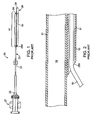
- FIG. 1 illustrates an aspiration catheter 20 suited for use in the treatment and removal of occlusions in blood vessels.
- Catheter 20 has a fitting 27 mounted at the proximal end in fluid communication with a proximal aspiration port 23.
- Catheter 20 includes an elongate tubular body 21 having a distal tip 26.
- Distal tip 26 can include a radiopaque marker (not shown) to aid in fluoroscopically locating tip 26 during insertion into the patient, and tip 26 is preferably soft to prevent damage to the patient's vasculature.
- Elongate tubular body 21 includes an aspiration tube 31 extending from fitting 27 to a location at or adjacent the distal end of tubular body 21.
- Aspiration tube 31 includes a tubular wall that defines an open aspiration lumen 12 (shown in FIG. 2 ), which extends the full length of tube 31.
- Aspiration lumen 12 fluidly connects aspiration port 23 disposed at or adjacent the proximal end of tubular body 21 with a distal fluid port 24 disposed at or adjacent the distal end of tubular body 21.
- a source (not shown) of partial vacuum or "negative pressure" may be connected to the luer adaptor of fitting 27 to aspirate blood and particulates through aspiration lumen 12 of catheter 20.
- Catheter 20 further includes a dual lumen section 41 that is substantially shorter than the full length of catheter 20.
- Dual lumen section 41 includes a guidewire tube 51 that defines an open guidewire lumen 15 (shown in FIG. 2 ) sized and shaped to slidingly accept a medical guidewire therethrough.
- Guidewire tube 51 extends from an open proximal end 290 to an open distal end 29, alongside a distal portion of aspiration tube 31 such that aspiration lumen 12 and guidewire lumen 15 are in a parallel or side-by-side configuration.
- Dual lumen section 41 thus extends proximally from second fluid port 24 disposed at the distal end of aspiration tube 31 to open proximal end 290 of guidewire tube 51.
- FIG. 2 is an enlarged cross-sectional view of open proximal end 290 of guidewire tube 51, showing a guidewire 50 extending through guidewire lumen 15.
- open proximal end 290 which may also be referred to as a proximal guidewire port
- guidewire tube 51 is attached to the outer surface of aspiration tube 31.
- WO 02/26309 discribes a catheter in which a guidewire tube is attached to a main tube.
- Embodiments of the present invention relate to an elongate aspiration catheter for removing particles from a blood vessel.
- the catheter includes an elongate aspiration tube having an aspiration lumen defined by an inner surface of the aspiration tube.
- the aspiration tube has a proximal port and a distal port fluidly connected via the aspiration lumen.
- the catheter also includes a guidewire tube disposed alongside and not extending proximally beyond a distal portion of the aspiration tube.
- the guidewire tube has a guidewire lumen defined by an inner surface of the guidewire tube and has a proximal end opening and a distal end opening that are connected via the guidewire lumen.
- the guidewire tube includes a distal portion secured to the distal portion of the aspiration tube and a proximal portion that defines a detachable strain relief segment.
- the strain relief segment is minimally attached to the aspiration tube prior to application of a transverse force. When a transverse force is applied to urge the guidewire tube away from the aspiration tube, the strain relief segment is detached from the aspiration tube.
- Embodiments of the present invention also relate to a method of making an aspiration catheter.
- An elongate, flexible first tube is provided, the first tube having a single lumen extending longitudinally therethrough.
- a flexible second tube is provided, the second tube having a lumen extending longitudinally therethrough and being open at proximal and distal ends thereof.
- the second tube is substantially shorter than the first tube.
- the second tube is secured beside a distalmost portion of the first tube such that a proximal portion of the second tube forms a detachable strain relief segment, wherein the strain relief segment is minimally attached to the aspiration tube.
- FIG. 1 is a side view of a prior art aspiration catheter.
- FIG. 2 is an enlarged longitudinal cross-sectional view of the proximal guidewire port of the aspiration catheter of FIG. 1 , with a guidewire extending within the guidewire lumen.
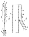
- FIG. 3 is a side view of an aspiration catheter according to an embodiment of the present invention.
- FIG. 4 is an enlarged longitudinal cross-sectional view of a strain relief segment of the aspiration catheter of FIG. 3 in accordance with an embodiment of the present invention, with a guidewire extending within the guidewire lumen.
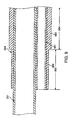
- FIG. 5 is an illustration of a strain relief segment according to an embodiment of the present invention, without a guidewire extending through the guidewire lumen.
- FIG. 6 is an illustration of the strain relief segment shown in FIG. 5 , with a guidewire extending within the guidewire lumen.
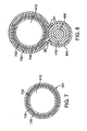
- FIG. 7 is a transverse cross sectional view of an aspiration catheter in accordance with the present invention taken along line 7 - 7 in FIG. 3 .
- FIG. 8 is a transverse cross sectional view of an aspiration catheter in accordance with the present invention taken along line 8 - 8 in FIG. 3 .
- FIG. 9 is an enlarged longitudinal cross-sectional view of a strain relief segment in accordance with another embodiment of the present invention.
- FIG. 10 is an enlarged longitudinal cross-sectional view of a strain relief segment in accordance with another embodiment of the present invention.
- FIG. 11 is an illustration of the strain relief segment shown in FIG. 5 as the aspiration catheter is withdrawn from a body lumen.
- distal and proximal are used in the following description with respect to a position or direction relative to the treating clinician.
- distal or disally are a position distant from or in a direction away from the clinician.
- Proximal and “proximally” are a position near or in a direction toward the clinician.
- Embodiments of the present invention are directed to a rapid-exchange aspiration catheter having an aspiration tube with an aspiration lumen extending therethrough and a substantially shorter guidewire tube having a guidewire lumen extending therethrough attached to a distal portion of the aspiration tube
- a short proximal portion of the guidewire tube defines a detached or detachable strain relief segment to prevent the above-described problem of the guidewire tearing the wall of the guidewire shaft.
- forces applied in a transverse direction to separate the guidewire from the catheter are redirected by a strain relief segment to result in an attempt to peel the guidewire tube away from the aspiration tube rather than resulting in the guidewire tearing the wall of the guidewire tube.
- the incorporation of a strain relief segment at the proximal end of the guidewire tube improves the catheter's resistance to wall tearing because the force required to peel the guidewire tube away from the aspiration tube has been found to be several times the force required to tear the wall of the guidewire tube. Further explanation and details will now be described with reference to FIGS. 3-11 .
- FIG. 3 illustrates a rapid-exchange or single operator aspiration catheter 320 particularly suited for use in the treatment and removal of occlusions in blood vessels.
- Catheter 320 has an elongate tubular body 321 including an aspiration tube 331 and a substantially shorter guidewire tube 351 along a distal portion of catheter 320.
- Guidewire tube 351 includes a strain relief segment 352 at a proximal end thereof.
- strain relief segment 352 is a short portion of guidewire tube 351 that is detached from aspiration tube 331. Detached strain relief segment 352 prevents the above-described problem of the guidewire tearing the guidewire shaft.
- strain relief segment 352 may be between 0.50 millimeters and one centimeter in length.
- a fitting 327 is in fluid communication with a proximal aspiration port 323.
- a source (not shown) of partial vacuum or "negative pressure” may be connected to the luer adaptor of fitting 327 to aspirate blood and particulates through an aspiration lumen 412, shown in FIG. 4 , of catheter 320.
- Aspiration lumen 412 is unobstructed to provide efficient aspiration.
- a distal tip 326 is disposed at the distal end of elongate tubular body 321.
- Distal tip 326 can include a radiopaque marker (not shown) to aid in fluoroscopically locating tip 326 during insertion into the patient, and tip 326 is preferably soft to prevent damage to the patient's vasculature.
- Aspiration tube 331 extends from fitting 327 to a location at or adjacent the distal end of tubular body 321.
- aspiration tube 331 has a tubular wall that defines an open aspiration lumen 412, which extends the full length of aspiration tube 331.
- Aspiration lumen 412 fluidly connects a first aspiration port 323 disposed at or adjacent the proximal end of tubular body 321 with a second fluid port 324 disposed at or adjacent the distal end of tubular body 321.
- second fluid port 324 forms an oblique opening that faces away from guidewire tube 351.
- fluid port 324 can form an opening that is orthogonal (not shown) to aspiration tube 331.
- aspiration catheter 320 is a laminated structure as described herein with respect to FIGS. 7-8 .
- aspiration tube 331 and/or guidewire tube 351 may have another configuration, such as for example a single-layer tubular structure.
- Catheter 320 further includes a dual lumen section 341 that is substantially shorter than the full length of catheter 320 where guidewire tube 351 is disposed adjacent to the distal portion of aspiration tube 331.
- guidewire tube 351 has a tubular wall that defines a guidewire lumen 415, which extends the full length of guidewire tube 351 from open distal end 329 at catheter distal tip 326 to open proximal end 390 of guidewire tube 351.
- Guidewire lumen 415 is sized and shaped to slidingly accept a medical guidewire 450 therethrough.
- Guidewire tube 351 extends alongside a distal portion of aspiration tube 331 such that aspiration lumen 412 and guidewire lumen 415 are in a parallel or side-by-side configuration. Dual lumen section 341 thus proximally extends from second fluid port 324 disposed at the distal end of aspiration tube 331 to open proximal end 390 of guidewire tube 351. In various embodiments, dual lumen section 341 may be less than 10 cm in length or may proximally extend 30 cm or longer from distal tip 326.
- Aspiration catheter 320 During delivery of aspiration catheter 320, the proximal end of a medical guidewire 450 is inserted into open distal end 329 of guidewire lumen 415, and guidewire tube 351 is slidingly advanced over guidewire 450. Only a short portion, i.e., dual lumen section 341, of catheter 320 rides over guidewire 450, which remains in guidewire lumen 415 and does not enter aspiration lumen 412 of the aspiration catheter 320. Thus, single operator aspiration catheter 320 does not require an extra long guidewire or a guidewire extender and may be handled by only one clinician. Aspiration catheter 320 may be used with a medical guidewire having a standard length of about 185 cm. Aspiration catheter 320 may be about 160 cm in length, although this length can be varied as desired.
- a relatively short, proximal portion of guidewire tube 351 that includes open proximal end 390 is detached from and independent of the outer surface of aspiration tube 331.
- This detached proximal portion defines a strain relief segment 352.
- guidewire tube 351 may have a length of approximately 10-30 cm.
- strain relief segment 352 may be between 0.50 millimeters and one centimeter in length.
- strain relief segment 352 may have a length between 0.5-10% of the total length of guidewire tube 351.
- Strain relief segment 352 is shown in FIGS. 3-4 as being curved away from aspiration tube 331 in order to illustrate that strain relief segment 352 is detached from aspiration tube 331. However, as explained in more detail with reference to FIGS. 5-6 , strain relief segment 352 lies generally parallel with and adjacent to aspiration tube 331 when no forces are applied thereto.
- a distal portion 354 of guidewire tube 351 is attached to the outer surface of aspiration tube 331.
- a relatively short, distal end 356 of guidewire tube 351 that includes distal opening 329 extends beyond second fluid port 324 of aspiration tube 331 to define distal tip 326 of catheter 320.
- aspiration tube 331 may extend beyond distal opening 329 of guidewire tube 351 such that the distal end of aspiration tube 331 defines the distal tip of the aspiration catheter. Further, aspiration tube 331 and guidewire tube 351 may extend to the same distal point such that the distal ends of both tubes define the distal tip of the aspiration catheter.
- FIG. 5 is an illustration of detached strain relief segment 352 with no forces applied thereto and without a guidewire extending through guidewire lumen 415.
- strain relief segment 352 lies generally parallel with and adjacent to aspiration tube 331. However, strain relief segment 352 is not attached to aspiration tube 331.
- Detached strain relief segment 352 is made from a flexible material such that it can fold distally over distal portion 354 of guidewire tube 351, which is attached to aspiration tube 331, as shown, for example, in FIG. 11 . Folded strain relief segment 352 may be tracked along a vessel wall 1158 of a body lumen 1159 without causing damage to the tissue if aspiration catheter 320 is withdrawn through the vessel without a guidewire.
- FIG. 6 is an illustration of detached strain relief segment 352 with guidewire 450 extending through guidewire lumen 415.
- guidewire 450 may apply forces to guidewire tube 351 that cause strain relief segment 352 to extend away from the outer surface of aspiration tube 331.
- strain relief segment 352 is no longer generally parallel with or adjacent to aspiration tube 331.
- the transverse force applied by guidewire 450 attempts to separate or rip distal portion 354 of guidewire tube 351 from aspiration tube 331.
- the strength of the attachment between distal portion 354 of guidewire tube 351 and aspiration tube 331 is strong enough to resist the peeling force applied by guidewire 450 under the expected clinical conditions.
- FIG. 7 is a transverse cross-sectional view of aspiration tube 331 taken along line 7 - 7 in FIG. 3 .
- the tubular wall of aspiration tube 331 includes an outer jacket 734 adhered about an inner liner 733 with a reinforcement layer 735 interposed therebetween.
- Aspiration tube 331 defines open aspiration lumen 412 along a length thereof as described above.
- the transverse cross-section of aspiration tube 331 is generally circular in shape.
- aspiration lumen 412 may have a diameter of about 1.143 mm (0.045 inch).
- Inner liner 733 and outer jacket 734 may be made from thermoplastic resins that are the same or are at least chemically compatible to permit thermal (melt) or solvent bonding between liner 733 and jacket 734 through the interstices of reinforcement layer 735.
- suitable thermoplastic resins include amides, polyamides, polyethylene block amide copolymers (PEBA), polyurethanes, and polyolefins such as polyethylenes or polypropylene.
- PEBA polyethylene block amide copolymers
- polyurethanes polyurethanes
- polyolefins such as polyethylenes or polypropylene.
- inner liner 733 and outer jacket 734 may be incompatible for melt bonding, but can be adhesively bonded together through the interstices of reinforcement layer 735.
- Reinforcement layer 735 can be formed from a braided or coiled filament of stainless steel, work-hardenable nickel-cobalt based superalloy, platinum alloy, refractory metal alloy such as tungsten or tantalum, or a combination thereof.
- the filaments of reinforcement layer 735 may have a cross-section that is round, oval, flat, or rectangular.
- the distal region of elongate tubular body 321 is preferably more flexible than the proximal region, and this can be achieved by providing a braid or coil density at the distal end that is greater than the braid or coil density at the proximal end.
- the braid or coil of reinforcement layer 735 has sufficiently large coil spacing or braid interstices to permit liner 733 and jacket 734 to be secured together therethrough.
- reinforcement layer 735 comprises a braid of flat stainless steel wire measuring 0.038 mm (0.0015 inch) wide and 0.013 mm (0.0005 inch) thick, the braid having a pick count that varies from about 45 picks per longitudinal inch along the catheter proximal region to about 70 picks per longitudinal inch along the catheter distal region.
- Pick, or pic is a term well known to one of skill in the art of catheters and refers to the intersection or crossing of two filaments in a woven tubular braid.
- FIG. 8 is a transverse cross-sectional view of dual lumen section 341 of aspiration catheter 320 taken along line 8 - 8 in FIG. 3 .
- Aspiration lumen 412 defined by aspiration tube 331 and guidewire lumen 415 defined by guidewire tube 351 are in a parallel or side-by-side configuration.
- Guidewire 450 is shown within guidewire lumen 415 in FIG. 8 , but not in FIG. 3 .
- the diameter of guidewire lumen 415 may range from about 0.381 mm (0.015 inch) to about 0.508 mm (0.020 inch) for receiving medical guidewire 450.
- an over sleeve 844 surrounds and secures together guidewire tube 351 and aspiration tube 331.
- Over sleeve 844 may also be made of suitable thermoplastic resins such as amides, polyamides, PEBA, polyurethanes, and polyolefins such as polyethylenes or polypropylenes.
- suitable thermoplastic resins such as amides, polyamides, PEBA, polyurethanes, and polyolefins such as polyethylenes or polypropylenes.
- the material for outer sleeve 844 may be the same as or may at least be chemically compatible with jacket 734 of aspiration tube 331 to be thermally or solvent bonded thereto.
- jacket 734 is made of polyamide
- over sleeve 844 is made of 40D durometer PEBA.
- outer jacket 734 of aspiration tube 331 may be removed from the portion of aspiration tube 331 within dual lumen section 341.
- Outer jacket 734 may be selectively removed from aspiration tube 331 by a laser ablation process disclosed in U.S. Pat. No. 6,059,769 .
- Over sleeve 844 can be shrunk and molded into place around guidewire tube 351 and the altered portion of aspiration tube 331 using removable shrink tubing as a tool, similar to the technique described in the '769 patent.
- outer jacket 734 is removed from a section of aspiration tube 331 proximal to dual lumen section 341.
- the removed portion of outer jacket 734 can be replaced with a filler material having a different flexibility to advantageously vary the stiffness along elongate tubular body 321.
- An additional section of over sleeve 844 or an alternative polymer resin may be used as the filler material.
- guidewire tube 351 may be fabricated from flexible low-friction polymers such as polytetrafluoroethylene (PTFE) or a polyolefin. Alternatively, guidewire tube 351 may be made from a polymer selected without regard to its friction properties, and a slippery coating (not shown) can be applied to lumen 415 to reduce friction against a guidewire.
- PTFE polytetrafluoroethylene
- a slippery coating (not shown) can be applied to lumen 415 to reduce friction against a guidewire.
- Aspiration catheter 320 is constructed by providing a first elongate flexible tube such as aspiration tube 331 having reinforcement layer 735 encapsulated within a wall of the tube. Aspiration tube 331 has only one lumen such as aspiration lumen 412 extending therethrough. Aspiration tube 331 may be constructed by a reel-to-reel process such as extruding inner liner 733, braiding reinforcement layer 735 around liner 733, and extruding jacket 734 over reinforcement layer 735, as disclosed in the '769 patent discussed above. Other well-known methods may be used to make the laminated structure of aspiration tube 331.
- a second elongate flexible tube that is substantially shorter than the first elongate flexible tube such as guidewire tube 351 is provided having lumen 415 extending longitudinally therethrough.
- Guidewire tube 351 may be made from paste-extruded PTFE or from a melt-extruded thermoplastic as mentioned above.
- jacket 734 may be removed from at least a longitudinal portion of the first tube that is to be secured to the second tube. Selectively removing jacket 734 reduces the outside dimensions of aspiration catheter 320 by eliminating one lamination layer.
- Soft catheter tip 326 can be the distal end of guidewire tube 351, or can be a separate component that is molded onto or otherwise secured at the distal end of catheter 320 at any desired step of the manufacturing process.
- guidewire tube 351 is formed from a material that has a high thermal bonding ability so as to form a strong thermal bond between guidewire tube distal portion 354 and aspiration tube 331.
- guidewire tube 351 may be formed from suitable thermoplastic resins such as amides, polyamides, PEBA, polyurethanes, and polyolefins such as polyethylenes or polypropylenes. If desired, a slippery coating can be applied to lumen 415 to reduce friction against a guidewire.
- a thermal bond may be formed between guidewire tube 351 and aspiration tube 331 by utilizing removable heat shrink tubing as a tool, similar to the technique described in the '769 patent.
- the heat shrink tubing is removed after guidewire tube 351 and aspiration tube 331 are bonded together.
- over sleeve 844 is utilized as the securement means, over sleeve 844 can be shrunk and molded into place around guidewire tube 351 and aspiration tube 331 using removable shrink tubing as a tool, similar to the technique described in the '769 patent.
- the securement means between guidewire tube distal portion 354 and aspiration tube 331 is the simultaneous and contiguous formation of guidewire tube 351 and aspiration tube 331 in a unitary two-lumen extrusion.
- An extruded two lumen precursor shaft can be made of suitable thermoplastic resins as described above, using a continuous thermoplastic extrusion process to create pieces of tubing that are cut to the desired length for an aspiration catheter.
- the extruded two lumen precursor shaft can be made of non thermoplastic resin such as PTFE using a cold, paste extrusion process.
- guidewire tube 351 can be formed by removing material that is collinear with guidewire tube 351 and proximal to dual lumen section 341.
- distal tip 326 can be formed by removing material that is collinear with aspiration tube 331 and distal to second fluid port 324.
- Strain relief segment 352 can be formed by cutting between aspiration lumen 412 and guidewire lumen 415 to form a relatively short, proximal portion of guidewire tube 351 that it is detached from and independent of aspiration tube 331. Cutting and/or removal of material to form single operator aspiration catheter 320 from an extruded two lumen precursor shaft can be done with well known tools such as a sharp blade, a heated wire, a laser beam or other suitable device.
- a detachable strain relief segment may be "tacked” or minimally attached to the aspiration tube.
- "Minimally attached” as used herein is intended to mean that the strain relief segment is attached to the aspiration tube with only enough bond strength or adhesion to hold it adjacent to the aspiration tube, such that the strain relief feature may be activated when a transverse peeling force is applied. If a transverse peeling force above a predetermined amount is applied, the strain relief segment becomes detached from, viz., rips or tears away from, the aspiration tube in order to prevent the above-described problem of the guidewire tearing through the guidewire shaft. If such a transverse peeling force is not applied, the strain relief segment remains attached to the aspiration tube.
- a guidewire tube 951 includes a minimally attached strain relief segment 952 at a proximal end thereof.
- Guidewire tube 951 is similar to guidewire tube 351 described above, except that strain relief segment 952 is a short proximal portion of guidewire tube 951 that is minimally attached to the outer surface of aspiration tube 331.
- strain relief segment 952 may be between 0.50 millimeters and one centimeter in length, or may have a length between 0.5-10% of the total length of guidewire tube 951.
- the remaining distal portion 954 of guidewire tube 951 is securely attached to the outer surface of aspiration tube 331.
- the guidewire may apply a transverse peeling force to guidewire tube 951 that is sufficient to cause strain relief segment 952 to become detached from and subsequently extend away from the outer surface of aspiration tube 331.
- the transverse force applied by the guidewire does not separate or rip distal portion 954 of guidewire tube 951 from aspiration tube 331, because the attachment between distal portion 954 of guidewire tube 951 and aspiration tube 331 is strong enough to resist the peeling force applied by the guidewire under the expected clinical conditions.
- an over sleeve 944 having a reduced wall thickness in the strain relief region may be used.
- Over sleeve 944 surrounds and secures guidewire tube 951 and aspiration tube 331.
- Over sleeve 944 includes a proximal portion 960 and a distal portion 962.
- Over sleeve proximal portion 960 has a first thickness
- over sleeve distal portion 962 has a second thickness that is greater than the first thickness.
- Proximal portion 960 overlays strain relief segment 952, while distal portion 962 overlays distal portion 954 of guidewire tube 951.
- proximal portion 960 of over sleeve 944 holds strain relief segment 952 against aspiration tube 331.
- proximal portion 960 will split apart to allow strain relief segment 952 to become detached from aspiration tube 331.
- relatively thicker distal portion 962 of over sleeve 944 remains intact and continues to secure guidewire tube distal portion 954 to aspiration tube 330.
- Over sleeve proximal portion 960 may be formed by displacing the material of over sleeve 944 during assembly of the catheter components. Over sleeve 944 may be shrunk and molded into place around guidewire tube 951 and aspiration tube 331, such as by using a removable heat shrink tubing similar to the technique described in the '769 patent. Over sleeve 944 may be made of suitable thermoplastic resins such as amides, polyamides, PEBA, polyurethanes, and polyolefins such as polyethylenes or polypropylenes. During the heat shrinking operation, the material of over sleeve 944 will flow in response to the thermal parameters and movement relative to the heat source. Thus, by controlling the heat source, the thickness of the material in the strain relief region may be thermally reduced.
- FIG. 10 Another embodiment for minimally attaching the strain relief segment of the guidewire tube to the aspiration tube is illustrated in FIG. 10 .
- a guidewire tube 1051 of PTFE includes a strain relief segment 1052 at a proximal end thereof, wherein strain relief segment 1052 is a short proximal portion of guidewire tube 1051 that is minimally attached to the outer surface of aspiration tube 331 by using a thermal bond.
- the thermal bonding ability of PTFE is relatively poor, thus resulting in a minimal or weak bond between strain relief segment 1052 and aspiration tube 331. When no forces are applied, the thermal bond holds strain relief segment 1052 against aspiration tube 331.
- the thermal bond may be broken to allow strain relief segment 1052 to become detached from aspiration tube 331.
- the remaining distal portion 1054 of guidewire tube 1051 is securely attached to the outer surface of aspiration tube 331 by an adhesive, a solvent bond, and/or an over sleeve, as discussed in previous embodiments, such that in contrast, distal portion 1054 remains secured alongside aspiration tube 330 despite any forces applied thereto.
Landscapes
- Health & Medical Sciences (AREA)
- Life Sciences & Earth Sciences (AREA)
- Animal Behavior & Ethology (AREA)
- Veterinary Medicine (AREA)
- Public Health (AREA)
- Engineering & Computer Science (AREA)
- Biomedical Technology (AREA)
- Heart & Thoracic Surgery (AREA)
- General Health & Medical Sciences (AREA)
- Anesthesiology (AREA)
- Hematology (AREA)
- Pulmonology (AREA)
- Biophysics (AREA)
- Surgery (AREA)
- Orthopedic Medicine & Surgery (AREA)
- Vascular Medicine (AREA)
- Nuclear Medicine, Radiotherapy & Molecular Imaging (AREA)
- Medical Informatics (AREA)
- Molecular Biology (AREA)
- Media Introduction/Drainage Providing Device (AREA)
Applications Claiming Priority (2)
| Application Number | Priority Date | Filing Date | Title |
|---|---|---|---|
| US12/052,892 US8066677B2 (en) | 2008-03-21 | 2008-03-21 | Rapid exchange catheter with tear resistant guidewire shaft |
| PCT/US2009/035808 WO2009117240A1 (en) | 2008-03-21 | 2009-03-03 | Rapid exchange catheter with tear resistant guidewire shaft |
Publications (2)
| Publication Number | Publication Date |
|---|---|
| EP2271392A1 EP2271392A1 (en) | 2011-01-12 |
| EP2271392B1 true EP2271392B1 (en) | 2013-05-08 |
Family
ID=40565061
Family Applications (1)
| Application Number | Title | Priority Date | Filing Date |
|---|---|---|---|
| EP09723078.3A Active EP2271392B1 (en) | 2008-03-21 | 2009-03-03 | Rapid exchange catheter with tear resistant guidewire shaft |
Country Status (4)
| Country | Link |
|---|---|
| US (1) | US8066677B2 (enExample) |
| EP (1) | EP2271392B1 (enExample) |
| JP (1) | JP5746014B2 (enExample) |
| WO (1) | WO2009117240A1 (enExample) |
Families Citing this family (34)
| Publication number | Priority date | Publication date | Assignee | Title |
|---|---|---|---|---|
| EP2120737B1 (en) | 2007-02-05 | 2020-04-01 | Boston Scientific Limited | Thrombectomy apparatus |
| US11660190B2 (en) | 2007-03-13 | 2023-05-30 | Edwards Lifesciences Corporation | Tissue anchors, systems and methods, and devices |
| US9510854B2 (en) | 2008-10-13 | 2016-12-06 | Boston Scientific Scimed, Inc. | Thrombectomy catheter with control box having pressure/vacuum valve for synchronous aspiration and fluid irrigation |
| JP5777936B2 (ja) * | 2010-07-16 | 2015-09-09 | テルモ株式会社 | 吸引カテーテル |
| US8968335B2 (en) * | 2010-10-27 | 2015-03-03 | Mitralign, Inc. | Hand operated device for controlled deployment of a tissue anchor and method of using the same |
| US9089350B2 (en) * | 2010-11-16 | 2015-07-28 | Boston Scientific Scimed, Inc. | Renal denervation catheter with RF electrode and integral contrast dye injection arrangement |
| JP5890979B2 (ja) * | 2011-08-01 | 2016-03-22 | 株式会社グッドマン | 吸引カテーテル |
| KR101241267B1 (ko) | 2011-08-24 | 2013-03-15 | 신경민 | 가이드와이어 안내 장치 |
| JP5307259B2 (ja) * | 2012-01-26 | 2013-10-02 | 日本ライフライン株式会社 | バルーンカテーテル |
| JP5964063B2 (ja) * | 2012-01-30 | 2016-08-03 | 株式会社グッドマン | カテーテル |
| JP6039199B2 (ja) * | 2012-03-12 | 2016-12-07 | 株式会社グッドマン | カテーテル |
| JP6244615B2 (ja) * | 2012-08-01 | 2017-12-13 | 日本ゼオン株式会社 | 内視鏡用カテーテル及び内視鏡処置具 |
| EP2900150B1 (en) | 2012-09-29 | 2018-04-18 | Mitralign, Inc. | Plication lock delivery system |
| WO2014152503A1 (en) | 2013-03-15 | 2014-09-25 | Mitralign, Inc. | Translation catheters, systems, and methods of use thereof |
| US10070857B2 (en) | 2013-08-31 | 2018-09-11 | Mitralign, Inc. | Devices and methods for locating and implanting tissue anchors at mitral valve commissure |
| CN104436417B (zh) * | 2013-09-13 | 2018-01-09 | 郭军 | 一种用于人体血管内灌注溶栓导管 |
| US20160250397A1 (en) * | 2013-10-30 | 2016-09-01 | Stephan Griffin | Aspiration maximizing catheter |
| US9433427B2 (en) | 2014-04-08 | 2016-09-06 | Incuvate, Llc | Systems and methods for management of thrombosis |
| US9248221B2 (en) | 2014-04-08 | 2016-02-02 | Incuvate, Llc | Aspiration monitoring system and method |
| US9883877B2 (en) | 2014-05-19 | 2018-02-06 | Walk Vascular, Llc | Systems and methods for removal of blood and thrombotic material |
| US10702292B2 (en) | 2015-08-28 | 2020-07-07 | Incuvate, Llc | Aspiration monitoring system and method |
| US10561440B2 (en) | 2015-09-03 | 2020-02-18 | Vesatek, Llc | Systems and methods for manipulating medical devices |
| US20170100142A1 (en) | 2015-10-09 | 2017-04-13 | Incuvate, Llc | Systems and methods for management of thrombosis |
| US10226263B2 (en) | 2015-12-23 | 2019-03-12 | Incuvate, Llc | Aspiration monitoring system and method |
| US10492805B2 (en) | 2016-04-06 | 2019-12-03 | Walk Vascular, Llc | Systems and methods for thrombolysis and delivery of an agent |
| CA3061230A1 (en) * | 2017-04-28 | 2018-11-01 | Merit Medical Systems, Inc. | Introducer with partially annealed reinforcement element and related systems and methods |
| US11678905B2 (en) | 2018-07-19 | 2023-06-20 | Walk Vascular, Llc | Systems and methods for removal of blood and thrombotic material |
| EP4146123A1 (en) * | 2020-05-05 | 2023-03-15 | Edwards Lifesciences Corporation | Delivery systems and delivery assemblies for prosthetic heart valves, methods of making and using the same |
| CN111973234B (zh) * | 2020-09-15 | 2025-07-01 | 上海鹏冠生物医药科技有限公司 | 一种体液提取器 |
| CN112471211B (zh) * | 2020-11-26 | 2023-07-14 | 山东融跃肉制品有限公司 | 一种食品加工用表皮处理装置 |
| EP4291261A1 (en) | 2021-02-15 | 2023-12-20 | Walk Vascular, LLC | Systems and methods for removal of blood and thrombotic material |
| US12274458B2 (en) | 2021-02-15 | 2025-04-15 | Walk Vascular, Llc | Systems and methods for removal of blood and thrombotic material |
| EP4329643A4 (en) | 2021-04-27 | 2025-03-12 | Contego Medical, Inc. | Thrombus aspiration system and methods for controlling blood loss |
| JP7656576B2 (ja) * | 2022-09-29 | 2025-04-03 | 日本ライフライン株式会社 | 電極カテーテル及びカテーテルシャフトの製造方法 |
Family Cites Families (14)
| Publication number | Priority date | Publication date | Assignee | Title |
|---|---|---|---|---|
| US5217482A (en) * | 1990-08-28 | 1993-06-08 | Scimed Life Systems, Inc. | Balloon catheter with distal guide wire lumen |
| US5487730A (en) | 1992-12-30 | 1996-01-30 | Medtronic, Inc. | Balloon catheter with balloon surface retention means |
| CA2113684A1 (en) | 1993-01-19 | 1994-07-20 | Robert L. Wilcox | Single-lumen over-the-wire iab catheter |
| US5306261A (en) * | 1993-01-22 | 1994-04-26 | Misonix, Inc. | Catheter with collapsible wire guide |
| US5336184A (en) | 1993-07-15 | 1994-08-09 | Teirstein Paul S | Rapid exchange catheter |
| WO1996000099A1 (en) | 1994-06-24 | 1996-01-04 | Advanced Cardiovascular Systems Inc. | Catheters having a reusable proximal body |
| US5690642A (en) | 1996-01-18 | 1997-11-25 | Cook Incorporated | Rapid exchange stent delivery balloon catheter |
| JP3889869B2 (ja) * | 1997-11-04 | 2007-03-07 | オリンパス株式会社 | 超音波プローブ |
| US6059769A (en) | 1998-10-02 | 2000-05-09 | Medtronic, Inc. | Medical catheter with grooved soft distal segment |
| US6482184B1 (en) | 2000-09-29 | 2002-11-19 | Advanced Infusion, Inc. | Attachable catheter |
| US7273486B2 (en) | 2003-04-11 | 2007-09-25 | Medtronic Vascular, Inc. | Catheter with a convertible proximal catheter shaft |
| US7208001B2 (en) | 2003-04-24 | 2007-04-24 | Medtronic Vascular, Inc. | Catheter with detached proximal inflation and guidewire shafts |
| CA2545167A1 (en) * | 2003-11-07 | 2005-05-19 | Kaneka Corporation | Aspiration catheter |
| US8298210B2 (en) | 2005-10-26 | 2012-10-30 | Medtronic Vascular, Inc. | Catheter having oval aspiration lumen and method of making |
-
2008
- 2008-03-21 US US12/052,892 patent/US8066677B2/en active Active
-
2009
- 2009-03-03 EP EP09723078.3A patent/EP2271392B1/en active Active
- 2009-03-03 JP JP2011500849A patent/JP5746014B2/ja active Active
- 2009-03-03 WO PCT/US2009/035808 patent/WO2009117240A1/en not_active Ceased
Also Published As
| Publication number | Publication date |
|---|---|
| EP2271392A1 (en) | 2011-01-12 |
| US8066677B2 (en) | 2011-11-29 |
| JP2011515150A (ja) | 2011-05-19 |
| WO2009117240A1 (en) | 2009-09-24 |
| US20090240206A1 (en) | 2009-09-24 |
| JP5746014B2 (ja) | 2015-07-08 |
Similar Documents
| Publication | Publication Date | Title |
|---|---|---|
| EP2271392B1 (en) | Rapid exchange catheter with tear resistant guidewire shaft | |
| US8298210B2 (en) | Catheter having oval aspiration lumen and method of making | |
| US12295595B2 (en) | Aspiration catheter systems and methods of use | |
| AU2022204503B2 (en) | Rapid aspiration thrombectomy system and method | |
| CN114916978B (zh) | 单操作者颅内医疗装置输送系统和使用方法 | |
| JP2009513246A5 (enExample) | ||
| US20040049225A1 (en) | Aspiration catheter | |
| HK40088770A (en) | Rapid aspiration thrombectomy system | |
| HK40079378A (zh) | 在颅内血管中执行医疗手术的系统、导管和导管前进装置 | |
| HK40025598A (en) | Rapid aspiration thrombectomy system | |
| HK40079058B (zh) | 单操作者颅内医疗装置输送系统和使用方法 | |
| HK40015164B (zh) | 抽吸导管系统和使用方法 | |
| HK40015164A (en) | Aspiration catheter systems and methods of use |
Legal Events
| Date | Code | Title | Description |
|---|---|---|---|
| PUAI | Public reference made under article 153(3) epc to a published international application that has entered the european phase |
Free format text: ORIGINAL CODE: 0009012 |
|
| 17P | Request for examination filed |
Effective date: 20101021 |
|
| AK | Designated contracting states |
Kind code of ref document: A1 Designated state(s): AT BE BG CH CY CZ DE DK EE ES FI FR GB GR HR HU IE IS IT LI LT LU LV MC MK MT NL NO PL PT RO SE SI SK TR |
|
| AX | Request for extension of the european patent |
Extension state: AL BA RS |
|
| DAX | Request for extension of the european patent (deleted) | ||
| 17Q | First examination report despatched |
Effective date: 20111221 |
|
| GRAP | Despatch of communication of intention to grant a patent |
Free format text: ORIGINAL CODE: EPIDOSNIGR1 |
|
| RIC1 | Information provided on ipc code assigned before grant |
Ipc: A61B 17/22 20060101ALI20121101BHEP Ipc: A61M 25/00 20060101AFI20121101BHEP |
|
| GRAS | Grant fee paid |
Free format text: ORIGINAL CODE: EPIDOSNIGR3 |
|
| GRAA | (expected) grant |
Free format text: ORIGINAL CODE: 0009210 |
|
| AK | Designated contracting states |
Kind code of ref document: B1 Designated state(s): AT BE BG CH CY CZ DE DK EE ES FI FR GB GR HR HU IE IS IT LI LT LU LV MC MK MT NL NO PL PT RO SE SI SK TR |
|
| REG | Reference to a national code |
Ref country code: GB Ref legal event code: FG4D |
|
| REG | Reference to a national code |
Ref country code: CH Ref legal event code: EP Ref country code: AT Ref legal event code: REF Ref document number: 610763 Country of ref document: AT Kind code of ref document: T Effective date: 20130515 |
|
| REG | Reference to a national code |
Ref country code: IE Ref legal event code: FG4D |
|
| REG | Reference to a national code |
Ref country code: DE Ref legal event code: R096 Ref document number: 602009015565 Country of ref document: DE Effective date: 20130704 |
|
| REG | Reference to a national code |
Ref country code: AT Ref legal event code: MK05 Ref document number: 610763 Country of ref document: AT Kind code of ref document: T Effective date: 20130508 |
|
| REG | Reference to a national code |
Ref country code: LT Ref legal event code: MG4D |
|
| REG | Reference to a national code |
Ref country code: NL Ref legal event code: VDEP Effective date: 20130508 |
|
| PG25 | Lapsed in a contracting state [announced via postgrant information from national office to epo] |
Ref country code: NO Free format text: LAPSE BECAUSE OF FAILURE TO SUBMIT A TRANSLATION OF THE DESCRIPTION OR TO PAY THE FEE WITHIN THE PRESCRIBED TIME-LIMIT Effective date: 20130808 Ref country code: SI Free format text: LAPSE BECAUSE OF FAILURE TO SUBMIT A TRANSLATION OF THE DESCRIPTION OR TO PAY THE FEE WITHIN THE PRESCRIBED TIME-LIMIT Effective date: 20130508 Ref country code: FI Free format text: LAPSE BECAUSE OF FAILURE TO SUBMIT A TRANSLATION OF THE DESCRIPTION OR TO PAY THE FEE WITHIN THE PRESCRIBED TIME-LIMIT Effective date: 20130508 Ref country code: LT Free format text: LAPSE BECAUSE OF FAILURE TO SUBMIT A TRANSLATION OF THE DESCRIPTION OR TO PAY THE FEE WITHIN THE PRESCRIBED TIME-LIMIT Effective date: 20130508 Ref country code: PT Free format text: LAPSE BECAUSE OF FAILURE TO SUBMIT A TRANSLATION OF THE DESCRIPTION OR TO PAY THE FEE WITHIN THE PRESCRIBED TIME-LIMIT Effective date: 20130909 Ref country code: SE Free format text: LAPSE BECAUSE OF FAILURE TO SUBMIT A TRANSLATION OF THE DESCRIPTION OR TO PAY THE FEE WITHIN THE PRESCRIBED TIME-LIMIT Effective date: 20130508 Ref country code: IS Free format text: LAPSE BECAUSE OF FAILURE TO SUBMIT A TRANSLATION OF THE DESCRIPTION OR TO PAY THE FEE WITHIN THE PRESCRIBED TIME-LIMIT Effective date: 20130908 Ref country code: GR Free format text: LAPSE BECAUSE OF FAILURE TO SUBMIT A TRANSLATION OF THE DESCRIPTION OR TO PAY THE FEE WITHIN THE PRESCRIBED TIME-LIMIT Effective date: 20130809 Ref country code: AT Free format text: LAPSE BECAUSE OF FAILURE TO SUBMIT A TRANSLATION OF THE DESCRIPTION OR TO PAY THE FEE WITHIN THE PRESCRIBED TIME-LIMIT Effective date: 20130508 Ref country code: ES Free format text: LAPSE BECAUSE OF FAILURE TO SUBMIT A TRANSLATION OF THE DESCRIPTION OR TO PAY THE FEE WITHIN THE PRESCRIBED TIME-LIMIT Effective date: 20130819 |
|
| PG25 | Lapsed in a contracting state [announced via postgrant information from national office to epo] |
Ref country code: PL Free format text: LAPSE BECAUSE OF FAILURE TO SUBMIT A TRANSLATION OF THE DESCRIPTION OR TO PAY THE FEE WITHIN THE PRESCRIBED TIME-LIMIT Effective date: 20130508 Ref country code: BG Free format text: LAPSE BECAUSE OF FAILURE TO SUBMIT A TRANSLATION OF THE DESCRIPTION OR TO PAY THE FEE WITHIN THE PRESCRIBED TIME-LIMIT Effective date: 20130808 Ref country code: HR Free format text: LAPSE BECAUSE OF FAILURE TO SUBMIT A TRANSLATION OF THE DESCRIPTION OR TO PAY THE FEE WITHIN THE PRESCRIBED TIME-LIMIT Effective date: 20130508 Ref country code: CY Free format text: LAPSE BECAUSE OF FAILURE TO SUBMIT A TRANSLATION OF THE DESCRIPTION OR TO PAY THE FEE WITHIN THE PRESCRIBED TIME-LIMIT Effective date: 20130508 |
|
| PG25 | Lapsed in a contracting state [announced via postgrant information from national office to epo] |
Ref country code: LV Free format text: LAPSE BECAUSE OF FAILURE TO SUBMIT A TRANSLATION OF THE DESCRIPTION OR TO PAY THE FEE WITHIN THE PRESCRIBED TIME-LIMIT Effective date: 20130508 |
|
| PG25 | Lapsed in a contracting state [announced via postgrant information from national office to epo] |
Ref country code: BE Free format text: LAPSE BECAUSE OF FAILURE TO SUBMIT A TRANSLATION OF THE DESCRIPTION OR TO PAY THE FEE WITHIN THE PRESCRIBED TIME-LIMIT Effective date: 20130508 Ref country code: DK Free format text: LAPSE BECAUSE OF FAILURE TO SUBMIT A TRANSLATION OF THE DESCRIPTION OR TO PAY THE FEE WITHIN THE PRESCRIBED TIME-LIMIT Effective date: 20130508 Ref country code: EE Free format text: LAPSE BECAUSE OF FAILURE TO SUBMIT A TRANSLATION OF THE DESCRIPTION OR TO PAY THE FEE WITHIN THE PRESCRIBED TIME-LIMIT Effective date: 20130508 Ref country code: CZ Free format text: LAPSE BECAUSE OF FAILURE TO SUBMIT A TRANSLATION OF THE DESCRIPTION OR TO PAY THE FEE WITHIN THE PRESCRIBED TIME-LIMIT Effective date: 20130508 Ref country code: SK Free format text: LAPSE BECAUSE OF FAILURE TO SUBMIT A TRANSLATION OF THE DESCRIPTION OR TO PAY THE FEE WITHIN THE PRESCRIBED TIME-LIMIT Effective date: 20130508 |
|
| PG25 | Lapsed in a contracting state [announced via postgrant information from national office to epo] |
Ref country code: IT Free format text: LAPSE BECAUSE OF FAILURE TO SUBMIT A TRANSLATION OF THE DESCRIPTION OR TO PAY THE FEE WITHIN THE PRESCRIBED TIME-LIMIT Effective date: 20130508 Ref country code: RO Free format text: LAPSE BECAUSE OF FAILURE TO SUBMIT A TRANSLATION OF THE DESCRIPTION OR TO PAY THE FEE WITHIN THE PRESCRIBED TIME-LIMIT Effective date: 20130508 Ref country code: NL Free format text: LAPSE BECAUSE OF FAILURE TO SUBMIT A TRANSLATION OF THE DESCRIPTION OR TO PAY THE FEE WITHIN THE PRESCRIBED TIME-LIMIT Effective date: 20130508 |
|
| PLBE | No opposition filed within time limit |
Free format text: ORIGINAL CODE: 0009261 |
|
| STAA | Information on the status of an ep patent application or granted ep patent |
Free format text: STATUS: NO OPPOSITION FILED WITHIN TIME LIMIT |
|
| 26N | No opposition filed |
Effective date: 20140211 |
|
| REG | Reference to a national code |
Ref country code: DE Ref legal event code: R097 Ref document number: 602009015565 Country of ref document: DE Effective date: 20140211 |
|
| PG25 | Lapsed in a contracting state [announced via postgrant information from national office to epo] |
Ref country code: LU Free format text: LAPSE BECAUSE OF FAILURE TO SUBMIT A TRANSLATION OF THE DESCRIPTION OR TO PAY THE FEE WITHIN THE PRESCRIBED TIME-LIMIT Effective date: 20140303 |
|
| REG | Reference to a national code |
Ref country code: CH Ref legal event code: PL |
|
| GBPC | Gb: european patent ceased through non-payment of renewal fee |
Effective date: 20140303 |
|
| PG25 | Lapsed in a contracting state [announced via postgrant information from national office to epo] |
Ref country code: GB Free format text: LAPSE BECAUSE OF NON-PAYMENT OF DUE FEES Effective date: 20140303 Ref country code: CH Free format text: LAPSE BECAUSE OF NON-PAYMENT OF DUE FEES Effective date: 20140331 Ref country code: LI Free format text: LAPSE BECAUSE OF NON-PAYMENT OF DUE FEES Effective date: 20140331 |
|
| PG25 | Lapsed in a contracting state [announced via postgrant information from national office to epo] |
Ref country code: MT Free format text: LAPSE BECAUSE OF FAILURE TO SUBMIT A TRANSLATION OF THE DESCRIPTION OR TO PAY THE FEE WITHIN THE PRESCRIBED TIME-LIMIT Effective date: 20130508 |
|
| REG | Reference to a national code |
Ref country code: FR Ref legal event code: PLFP Year of fee payment: 8 |
|
| PG25 | Lapsed in a contracting state [announced via postgrant information from national office to epo] |
Ref country code: MC Free format text: LAPSE BECAUSE OF FAILURE TO SUBMIT A TRANSLATION OF THE DESCRIPTION OR TO PAY THE FEE WITHIN THE PRESCRIBED TIME-LIMIT Effective date: 20130508 |
|
| PG25 | Lapsed in a contracting state [announced via postgrant information from national office to epo] |
Ref country code: TR Free format text: LAPSE BECAUSE OF FAILURE TO SUBMIT A TRANSLATION OF THE DESCRIPTION OR TO PAY THE FEE WITHIN THE PRESCRIBED TIME-LIMIT Effective date: 20130508 Ref country code: HU Free format text: LAPSE BECAUSE OF FAILURE TO SUBMIT A TRANSLATION OF THE DESCRIPTION OR TO PAY THE FEE WITHIN THE PRESCRIBED TIME-LIMIT; INVALID AB INITIO Effective date: 20090303 |
|
| REG | Reference to a national code |
Ref country code: FR Ref legal event code: PLFP Year of fee payment: 9 |
|
| REG | Reference to a national code |
Ref country code: FR Ref legal event code: PLFP Year of fee payment: 10 |
|
| PG25 | Lapsed in a contracting state [announced via postgrant information from national office to epo] |
Ref country code: MK Free format text: LAPSE BECAUSE OF FAILURE TO SUBMIT A TRANSLATION OF THE DESCRIPTION OR TO PAY THE FEE WITHIN THE PRESCRIBED TIME-LIMIT Effective date: 20130508 |
|
| PGFP | Annual fee paid to national office [announced via postgrant information from national office to epo] |
Ref country code: DE Payment date: 20250218 Year of fee payment: 17 |
|
| PGFP | Annual fee paid to national office [announced via postgrant information from national office to epo] |
Ref country code: IE Payment date: 20250220 Year of fee payment: 17 |
|
| PGFP | Annual fee paid to national office [announced via postgrant information from national office to epo] |
Ref country code: FR Payment date: 20250218 Year of fee payment: 17 |