EP2271109B1 - Verfahren zur Codierung bewegter Bilder und Verfahren zur Decodierung bewegter Bilder - Google Patents
Verfahren zur Codierung bewegter Bilder und Verfahren zur Decodierung bewegter Bilder Download PDFInfo
- Publication number
- EP2271109B1 EP2271109B1 EP10182789.7A EP10182789A EP2271109B1 EP 2271109 B1 EP2271109 B1 EP 2271109B1 EP 10182789 A EP10182789 A EP 10182789A EP 2271109 B1 EP2271109 B1 EP 2271109B1
- Authority
- EP
- European Patent Office
- Prior art keywords
- picture
- motion vector
- coding
- block
- pictures
- Prior art date
- Legal status (The legal status is an assumption and is not a legal conclusion. Google has not performed a legal analysis and makes no representation as to the accuracy of the status listed.)
- Expired - Lifetime
Links
- 238000000034 method Methods 0.000 title claims description 140
- 239000013598 vector Substances 0.000 claims description 626
- 238000013500 data storage Methods 0.000 claims 1
- 230000002123 temporal effect Effects 0.000 description 46
- 238000012545 processing Methods 0.000 description 39
- 238000010586 diagram Methods 0.000 description 31
- 238000004364 calculation method Methods 0.000 description 18
- 238000004458 analytical method Methods 0.000 description 9
- 238000013139 quantization Methods 0.000 description 9
- 238000012935 Averaging Methods 0.000 description 6
- 238000004891 communication Methods 0.000 description 5
- 238000001228 spectrum Methods 0.000 description 5
- 238000006243 chemical reaction Methods 0.000 description 4
- 230000003044 adaptive effect Effects 0.000 description 3
- 230000000694 effects Effects 0.000 description 2
- 238000002474 experimental method Methods 0.000 description 2
- 239000000284 extract Substances 0.000 description 2
- 239000004973 liquid crystal related substance Substances 0.000 description 2
- 230000003287 optical effect Effects 0.000 description 2
- 230000009467 reduction Effects 0.000 description 2
- 230000001360 synchronised effect Effects 0.000 description 2
- 230000008901 benefit Effects 0.000 description 1
- 230000005540 biological transmission Effects 0.000 description 1
- 230000008859 change Effects 0.000 description 1
- 238000005094 computer simulation Methods 0.000 description 1
- 238000005516 engineering process Methods 0.000 description 1
- 230000006870 function Effects 0.000 description 1
- 238000010295 mobile communication Methods 0.000 description 1
- 238000004088 simulation Methods 0.000 description 1
- 238000012360 testing method Methods 0.000 description 1
- 230000009466 transformation Effects 0.000 description 1
- 230000000007 visual effect Effects 0.000 description 1
Images


Classifications
-
- H—ELECTRICITY
- H04—ELECTRIC COMMUNICATION TECHNIQUE
- H04N—PICTORIAL COMMUNICATION, e.g. TELEVISION
- H04N19/00—Methods or arrangements for coding, decoding, compressing or decompressing digital video signals
- H04N19/50—Methods or arrangements for coding, decoding, compressing or decompressing digital video signals using predictive coding
- H04N19/503—Methods or arrangements for coding, decoding, compressing or decompressing digital video signals using predictive coding involving temporal prediction
- H04N19/51—Motion estimation or motion compensation
- H04N19/577—Motion compensation with bidirectional frame interpolation, i.e. using B-pictures
-
- H—ELECTRICITY
- H04—ELECTRIC COMMUNICATION TECHNIQUE
- H04N—PICTORIAL COMMUNICATION, e.g. TELEVISION
- H04N19/00—Methods or arrangements for coding, decoding, compressing or decompressing digital video signals
- H04N19/10—Methods or arrangements for coding, decoding, compressing or decompressing digital video signals using adaptive coding
- H04N19/102—Methods or arrangements for coding, decoding, compressing or decompressing digital video signals using adaptive coding characterised by the element, parameter or selection affected or controlled by the adaptive coding
- H04N19/103—Selection of coding mode or of prediction mode
- H04N19/105—Selection of the reference unit for prediction within a chosen coding or prediction mode, e.g. adaptive choice of position and number of pixels used for prediction
-
- H—ELECTRICITY
- H04—ELECTRIC COMMUNICATION TECHNIQUE
- H04N—PICTORIAL COMMUNICATION, e.g. TELEVISION
- H04N19/00—Methods or arrangements for coding, decoding, compressing or decompressing digital video signals
- H04N19/10—Methods or arrangements for coding, decoding, compressing or decompressing digital video signals using adaptive coding
- H04N19/102—Methods or arrangements for coding, decoding, compressing or decompressing digital video signals using adaptive coding characterised by the element, parameter or selection affected or controlled by the adaptive coding
- H04N19/103—Selection of coding mode or of prediction mode
- H04N19/107—Selection of coding mode or of prediction mode between spatial and temporal predictive coding, e.g. picture refresh
-
- H—ELECTRICITY
- H04—ELECTRIC COMMUNICATION TECHNIQUE
- H04N—PICTORIAL COMMUNICATION, e.g. TELEVISION
- H04N19/00—Methods or arrangements for coding, decoding, compressing or decompressing digital video signals
- H04N19/10—Methods or arrangements for coding, decoding, compressing or decompressing digital video signals using adaptive coding
- H04N19/102—Methods or arrangements for coding, decoding, compressing or decompressing digital video signals using adaptive coding characterised by the element, parameter or selection affected or controlled by the adaptive coding
- H04N19/127—Prioritisation of hardware or computational resources
-
- H—ELECTRICITY
- H04—ELECTRIC COMMUNICATION TECHNIQUE
- H04N—PICTORIAL COMMUNICATION, e.g. TELEVISION
- H04N19/00—Methods or arrangements for coding, decoding, compressing or decompressing digital video signals
- H04N19/10—Methods or arrangements for coding, decoding, compressing or decompressing digital video signals using adaptive coding
- H04N19/134—Methods or arrangements for coding, decoding, compressing or decompressing digital video signals using adaptive coding characterised by the element, parameter or criterion affecting or controlling the adaptive coding
- H04N19/136—Incoming video signal characteristics or properties
- H04N19/137—Motion inside a coding unit, e.g. average field, frame or block difference
-
- H—ELECTRICITY
- H04—ELECTRIC COMMUNICATION TECHNIQUE
- H04N—PICTORIAL COMMUNICATION, e.g. TELEVISION
- H04N19/00—Methods or arrangements for coding, decoding, compressing or decompressing digital video signals
- H04N19/10—Methods or arrangements for coding, decoding, compressing or decompressing digital video signals using adaptive coding
- H04N19/134—Methods or arrangements for coding, decoding, compressing or decompressing digital video signals using adaptive coding characterised by the element, parameter or criterion affecting or controlling the adaptive coding
- H04N19/157—Assigned coding mode, i.e. the coding mode being predefined or preselected to be further used for selection of another element or parameter
- H04N19/16—Assigned coding mode, i.e. the coding mode being predefined or preselected to be further used for selection of another element or parameter for a given display mode, e.g. for interlaced or progressive display mode
-
- H—ELECTRICITY
- H04—ELECTRIC COMMUNICATION TECHNIQUE
- H04N—PICTORIAL COMMUNICATION, e.g. TELEVISION
- H04N19/00—Methods or arrangements for coding, decoding, compressing or decompressing digital video signals
- H04N19/10—Methods or arrangements for coding, decoding, compressing or decompressing digital video signals using adaptive coding
- H04N19/169—Methods or arrangements for coding, decoding, compressing or decompressing digital video signals using adaptive coding characterised by the coding unit, i.e. the structural portion or semantic portion of the video signal being the object or the subject of the adaptive coding
- H04N19/17—Methods or arrangements for coding, decoding, compressing or decompressing digital video signals using adaptive coding characterised by the coding unit, i.e. the structural portion or semantic portion of the video signal being the object or the subject of the adaptive coding the unit being an image region, e.g. an object
- H04N19/172—Methods or arrangements for coding, decoding, compressing or decompressing digital video signals using adaptive coding characterised by the coding unit, i.e. the structural portion or semantic portion of the video signal being the object or the subject of the adaptive coding the unit being an image region, e.g. an object the region being a picture, frame or field
-
- H—ELECTRICITY
- H04—ELECTRIC COMMUNICATION TECHNIQUE
- H04N—PICTORIAL COMMUNICATION, e.g. TELEVISION
- H04N19/00—Methods or arrangements for coding, decoding, compressing or decompressing digital video signals
- H04N19/10—Methods or arrangements for coding, decoding, compressing or decompressing digital video signals using adaptive coding
- H04N19/169—Methods or arrangements for coding, decoding, compressing or decompressing digital video signals using adaptive coding characterised by the coding unit, i.e. the structural portion or semantic portion of the video signal being the object or the subject of the adaptive coding
- H04N19/17—Methods or arrangements for coding, decoding, compressing or decompressing digital video signals using adaptive coding characterised by the coding unit, i.e. the structural portion or semantic portion of the video signal being the object or the subject of the adaptive coding the unit being an image region, e.g. an object
- H04N19/176—Methods or arrangements for coding, decoding, compressing or decompressing digital video signals using adaptive coding characterised by the coding unit, i.e. the structural portion or semantic portion of the video signal being the object or the subject of the adaptive coding the unit being an image region, e.g. an object the region being a block, e.g. a macroblock
-
- H—ELECTRICITY
- H04—ELECTRIC COMMUNICATION TECHNIQUE
- H04N—PICTORIAL COMMUNICATION, e.g. TELEVISION
- H04N19/00—Methods or arrangements for coding, decoding, compressing or decompressing digital video signals
- H04N19/42—Methods or arrangements for coding, decoding, compressing or decompressing digital video signals characterised by implementation details or hardware specially adapted for video compression or decompression, e.g. dedicated software implementation
- H04N19/423—Methods or arrangements for coding, decoding, compressing or decompressing digital video signals characterised by implementation details or hardware specially adapted for video compression or decompression, e.g. dedicated software implementation characterised by memory arrangements
-
- H—ELECTRICITY
- H04—ELECTRIC COMMUNICATION TECHNIQUE
- H04N—PICTORIAL COMMUNICATION, e.g. TELEVISION
- H04N19/00—Methods or arrangements for coding, decoding, compressing or decompressing digital video signals
- H04N19/44—Decoders specially adapted therefor, e.g. video decoders which are asymmetric with respect to the encoder
-
- H—ELECTRICITY
- H04—ELECTRIC COMMUNICATION TECHNIQUE
- H04N—PICTORIAL COMMUNICATION, e.g. TELEVISION
- H04N19/00—Methods or arrangements for coding, decoding, compressing or decompressing digital video signals
- H04N19/46—Embedding additional information in the video signal during the compression process
-
- H—ELECTRICITY
- H04—ELECTRIC COMMUNICATION TECHNIQUE
- H04N—PICTORIAL COMMUNICATION, e.g. TELEVISION
- H04N19/00—Methods or arrangements for coding, decoding, compressing or decompressing digital video signals
- H04N19/50—Methods or arrangements for coding, decoding, compressing or decompressing digital video signals using predictive coding
- H04N19/503—Methods or arrangements for coding, decoding, compressing or decompressing digital video signals using predictive coding involving temporal prediction
- H04N19/51—Motion estimation or motion compensation
- H04N19/573—Motion compensation with multiple frame prediction using two or more reference frames in a given prediction direction
-
- H—ELECTRICITY
- H04—ELECTRIC COMMUNICATION TECHNIQUE
- H04N—PICTORIAL COMMUNICATION, e.g. TELEVISION
- H04N19/00—Methods or arrangements for coding, decoding, compressing or decompressing digital video signals
- H04N19/50—Methods or arrangements for coding, decoding, compressing or decompressing digital video signals using predictive coding
- H04N19/503—Methods or arrangements for coding, decoding, compressing or decompressing digital video signals using predictive coding involving temporal prediction
- H04N19/51—Motion estimation or motion compensation
- H04N19/58—Motion compensation with long-term prediction, i.e. the reference frame for a current frame not being the temporally closest one
-
- H—ELECTRICITY
- H04—ELECTRIC COMMUNICATION TECHNIQUE
- H04N—PICTORIAL COMMUNICATION, e.g. TELEVISION
- H04N19/00—Methods or arrangements for coding, decoding, compressing or decompressing digital video signals
- H04N19/60—Methods or arrangements for coding, decoding, compressing or decompressing digital video signals using transform coding
- H04N19/61—Methods or arrangements for coding, decoding, compressing or decompressing digital video signals using transform coding in combination with predictive coding
-
- H—ELECTRICITY
- H04—ELECTRIC COMMUNICATION TECHNIQUE
- H04N—PICTORIAL COMMUNICATION, e.g. TELEVISION
- H04N19/00—Methods or arrangements for coding, decoding, compressing or decompressing digital video signals
- H04N19/70—Methods or arrangements for coding, decoding, compressing or decompressing digital video signals characterised by syntax aspects related to video coding, e.g. related to compression standards
Definitions
- the present invention relates to moving picture coding methods and moving picture decoding methods, and particularly to methods for performing inter picture prediction coding and inter picture prediction decoding of a current picture using previously processed pictures as reference pictures.
- Adaptive frame/field coding for JVT Video Coding ITU-T JVT-B071, L. Wang et al., presents the computer simulation results for core experiments A (frame coding), B (field coding) and E (picture level adaptive coding) defined in P. Borgwardt, "Core experiment on interlace video coding", ITU-T VCEG-059, 2 Jan. 2002 . for interlace video coding. Simulations were carried out for various interlace video sequences, including the six common sequences for interlace testing. The advantage of adaptive coding over frame or field coding is obvious. It is recommended that adoptive coding be adopted in JVT.
- data amount is generally compressed by utilizing the spatial and temporal redundancies that exist within a moving picture.
- frequency transformation is used as a method utilizing the spatial redundancies
- inter picture prediction coding is used as a method utilizing the temporal redundancies.
- inter picture prediction coding for coding a current picture, previously coded pictures earlier or later than the current picture in display order are used as reference pictures. The amount of motion of the current picture from the reference picture is estimated, and the difference between the picture data obtained by motion compensation based on that amount of motion and the picture data of the current picture is calculated, so that the temporal redundancies are eliminated. The spatial redundancies are further eliminated from this differential value so as to compress the data amount of the current picture.
- a picture which is coded not using inter picture prediction but using intra picture coding is referred to as an I-picture
- a picture which is coded using inter picture prediction with reference to one previously processed picture which is earlier or later than a current picture in display order is referred to as a P-picture
- a picture which is coded using inter picture prediction with reference to two previously processed pictures which are earlier or later than a current picture in display order is referred to as a B-picture (See ISO/IEC 14496-2 "Information technology - Coding of audio-visual objects - Part2: Visual" pp.218-219 ).
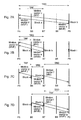
- Fig. 1A is a diagram showing relationship between respective pictures and the corresponding reference pictures in the above-mentioned moving picture coding method
- Fig. 1B is a diagram showing the sequence of the pictures in the bit stream generated by coding.
- a picture I1 is an I-picture
- pictures P5, P9 and P13 are P-pictures
- pictures B2, B3, B4, B6, B7, B8, B10, B11 and B12 are B-pictures.
- the P-pictures P5, P9 and P13 are coded using inter picture prediction from the I-picture I1 and P-pictures P5 and P9 respectively as reference pictures.
- the B-pictures B2, B3 and B4 are coded using inter picture prediction from the I-picture I1 and P-picture P5 respectively as reference pictures.
- the B-pictures B6, B7 and B8 are coded using the P-pictures P5 and P9 respectively as reference pictures
- the B-pictures B10, B11 and B12 are coded using the P-pictures P9 and P13 respectively as reference pictures.
- the reference pictures are coded prior to the pictures which refer to the reference pictures. Therefore, the bit stream is generated by the above coding in the sequence as shown in Fig. 1B .
- a coding mode called direct mode can be selected.
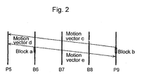
- An inter picture prediction method in direct mode will be explained with reference to Fig. 2.
- Fig. 2 is an illustration showing motion vectors in direct mode, and particularly showing the case of coding a block a in the picture B6 in direct mode.
- a motion vector c used for coding a block b in the picture P9 is utilized.
- the block b is co-located with the block a and the picture P9 is a backward reference picture of the picture B6.
- the motion vector c is a vector used for coding the block b and refers to the picture P5.
- the block a is coded using bi-prediction based on the reference blocks obtained from the forward reference picture P5 and the backward reference picture P9 using vectors parallel to the motion vector c.
- the motion vectors used for coding the block a are the motion vector d for the picture P5 and the motion vector e for the picture P9.
- the present invention has been conceived in order to solve the above-mentioned problem, and it is an object of the present invention to provide a moving picture coding method and a moving picture decoding method for avoiding efficiency reduction of coding B-pictures if a lot of B-pictures are located between an I-picture and a P-picture or between two P-pictures.
- the moving picture coding method of the present invention is a moving picture coding method as defined in claim 1.
- the present invention can be realized as such a moving picture coding method as mentioned above, but also as a moving picture coding apparatus including characteristic steps of the moving picture coding method as defined in claim 4.
- the present invention can be realized as a bit stream obtained by coding by the moving picture coding method so as to distribute it via a recording medium such as a CD-ROM or a transmission medium such as the Internet.
- Fig. 3 is a block diagram showing the structure of an embodiment of the moving picture coding apparatus using the moving picture coding method according to the present invention.
- the moving picture coding apparatus includes a reordering memory 101, a difference calculation unit 102, a residual error coding unit 103, a bit stream generation unit 104, a residual error decoding unit 105, an addition unit 106, a reference picture memory 107, a motion vector estimation unit 108, a mode selection unit 109, a coding control unit 110, switches 111 ⁇ 115 and a motion vector storage unit 116.
- the reordering memory 101 stores moving pictures inputted on a picture-to-picture basis in display order.
- the coding control unit 110 reorders the pictures stored in the reordering memory 101 in coding order.
- the coding control unit 110 also controls the operation of the motion vector storage unit 116 for storing motion vectors.
- the motion vector estimation unit 108 uses the previously coded and decoded picture data as a reference picture as a reference picture.
- the mode selection unit 109 determines a mode for coding macroblocks using the motion vector estimated by the motion vector estimation unit 108, and generates predictive image data based on the coding mode.
- the difference calculation unit 102 calculates the difference between the image data read out from the reordering memory 101 and the predictive image data inputted by the mode selection unit 109, and generates residual error image data.
- the residual error coding unit 103 performs coding processing such as frequency transform and quantization on the inputted residual error image data for generating the coded data.
- the bit stream generation unit 104 performs variable length coding or the like on the inputted coded data, and further adds the motion vector information, the coding mode information and other relevant information inputted by the mode selection unit 109 to the coded data so as to generate a bit stream.
- the residual error decoding unit 105 performs decoding processing such as inverse quantization and inverse frequency transform on the inputted coded data for generating decoded differential image data.
- the addition unit 106 adds the decoded differential image data inputted by the residual error decoding unit 105 and the predictive image data inputted by the mode selection unit 109 for generating decoded image data.
- the reference picture memory 107 stores the generated decoded image data.
- Fig. 4 is an illustration of pictures and relative indices.
- the relative indices are used for identifying uniquely reference pictures stored in the reference picture memory 107, and they are associated to respective pictures as shown in Fig. 4 .
- the relative indices are also used for indicating the reference pictures which are to be used for coding blocks using inter picture prediction.
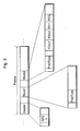
- Fig. 5 is a conceptual illustration of moving picture coded data format used by the moving picture coding apparatus.
- Coded data "Picture” for one picture includes header coded data "Header” included in the head of the picture, block coded data "Block1” for direct mode, block coded data "Block2” for the inter picture prediction other than the direct mode, and the like.
- the block coded data "Block2" for the inter picture prediction other than direct mode has a first relative index "RIdx1" and a second relative index "RIdx2" for indicating two reference pictures used for inter picture prediction, a first motion vector "MV1” and a second motion vector "MV2" in this order.
- the block coded data "Block1" for direct mode does not have the first and second relative indices "RIdx1" and “RIdx2" and the first and second motion vectors "MV1" and “MV2".
- the index which is to be used, the first relative index "RIdx1” or the second relative index “RIdx2”, can be determined by the prediction type "PredType".
- the first relative index "RIdx1” indicates a first reference picture
- the second relative index "RIdx2" indicates a second reference picture. In other words, whether a picture is a first reference picture or a second reference picture is determined based on where they are located in the bit stream.
- a P-picture is coded by inter picture prediction with uni-predictive reference using a previously coded picture which is located earlier or later in display order as a first reference picture
- a B-picture is coded by inter picture prediction with bi-predictive reference using previously coded pictures which are located earlier or later in display order as a first reference picture and a second reference picture.
- the first reference picture is explained as a forward reference picture
- the second reference picture is explained as a backward reference picture
- the first and second motion vectors for the first and second reference pictures are explained as a forward motion vector and a backward motion vector respectively.
- the values incremented by 1 from 0 are first assigned to the reference pictures earlier than the current picture from the picture closer to the current picture. After the values incremented by 1 from 0 are assigned to all the reference pictures earlier than the current picture, then the subsequent values are assigned to the reference pictures later than the current picture from the picture closer to the current picture.
- the values incremented by 1 from 0 are assigned to the reference pictures later than the current picture from the picture closer to the current picture. After the values incremented by 1 from 0 are assigned to all the reference pictures later than the current picture, then the subsequent values are assignee to the reference pictures earlier than the current picture from the picture closer to the current picture.
- Relative indices in a block are represented by variable length code words, and the codes with shorter lengths are assigned to the indices of the smaller values. Since the picture which is closest to the current picture is usually selected as a reference picture for inter picture prediction, coding efficiency is improved by assigning the relative index values in order of closeness to the current picture.
- Assignment of reference pictures to relative indices can be changed arbitrarily if it is explicitly indicated using buffer control signal in coded data (RPSL in Header as shown in Fig. 5 ). This enables to change the reference picture with the second relative index "0" to an arbitrary reference picture in the reference picture memory 107. As shown in Fig. 4B , assignment of reference indices to pictures can be changed, for example.
- Fig. 6 is an illustration showing the picture sequence in the reordering memory 101, and Fig. 6A shows the sequence in input order and Fig. 6B shows the reordered sequence.
- vertical lines show pictures, and the numbers indicated at the lower right of the pictures show the picture types (I, P and B) with the first alphabetical letters and the picture numbers indicating display order with the following numbers.
- a moving picture is inputted to the reordering memory 101 on a picture-to-picture basis in display order, for example.
- the coding control unit 110 reorders the pictures inputted to the reordering memory 101 in coding order.
- the pictures are reordered based on the reference relations in inter picture prediction coding, and more specifically, the pictures are reordered so that the pictures used as reference pictures are coded earlier than the pictures which use the reference pictures.
- a P-picture refers to one neighboring previously processed I or P-picture which is located earlier or later than the current P-picture in display order
- a B-picture refers to two neighboring previously processed pictures which are located earlier or later than the current B-picture in display order.
- the pictures are coded in the following order. First, a B-picture at the center of B-pictures (3 B-pictures in Fig. 6A , for instance) located between two P-pictures is coded, and then another B-picture closer to the earlier P-picture is coded. For example, the pictures B6, B7, B8 and P9 are coded in the order of P9, B7, B6 and B8.
- the picture pointed by the arrow refers to the picture at the origin of the arrow.
- B-picture B7 refers to P-pictures P5 and P9
- B6 refers to P5 and B7
- B8 refers to B7 and P9, respectively.
- the coding control unit 110 reorders the pictures in coding order, as shown in Fig. 6B .
- the pictures reordered in the reordering memory 101 are read out in a unit for every motion compensation.
- the unit of motion compensation is referred to as a macroblock which is 16 (horizontal) x 16 (vertical) pixels in size. Coding of the pictures P9, B7 B6 and B8 shown in Fig. 6A will be explained below in this order.
- the P-picture P9 is coded using inter picture prediction with reference to one previously processed picture located earlier or later than P9 in display order.
- the picture P5 is the reference picture, as mentioned above. P5 has already been coded and the decoded picture thereof is stored in the reference picture memory 107.
- the coding control unit 110 controls switches 113, 114 and 115 so as to be ON.
- the macroblocks in the picture P9 read out from the reordering memory 101 are thus inputted to the motion vector estimation unit 108, the mode selection unit 109 and the difference calculation unit 102 in this order.
- the motion vector estimation unit 108 estimates a motion vector of a macroblock in the picture P9, using the decoded picture data of the picture P5 stored in the reference picture memory 107 as a reference picture, and outputs the estimated motion vector to the mode selection unit 109.
- the mode selection unit 109 determines the mode for coding the macroblock in the picture P9 using the motion vector estimated by the motion vector estimation unit 108.
- the coding mode indicates the method of coding macroblocks.
- P-pictures it determines any of the coding methods, intra picture coding, inter picture prediction coding using a motion vector and inter picture prediction coding without using a motion vector (where motion is handled as "0").
- a method is selected so that a coding error is reduced with a small amount of bits.
- the mode selection unit 109 outputs the determined coding mode to the bit stream generation unit 104. If the coding mode determined by the mode selection unit 109 is inter picture prediction coding, the motion vector which is to be used for the inter picture prediction coding is outputted to the bit stream generation unit 104 and further stored in the motion vector storage unit 116.
- the mode selection unit 109 generates predictive image data based on the determined coding mode for generating to the difference calculation unit 102 and the addition unit 106. However, when selecting intra picture coding, the mode selection unit 109 does not output predictive image data. In addition, when selecting intra picture coding, the mode selection unit 109 controls the switches 111 and 112 to connect to "a" side and "c" side respectively, and when selecting inter picture prediction coding, it controls them to connect to "b" side and "d” side respectively. The case will be explained below where the mode selection unit 109 selects inter picture prediction coding.
- the difference calculation unit 102 receives the image data of the macroblock in the picture P9 read out from the reordering memory 101 and the predictive image data outputted from the mode selection unit 109. The difference calculation unit 102 calculates the difference between the image data of the macroblock in the picture P9 and the predictive image data, and generates the residual error image data for outputting to the residual error coding unit 103.
- the residual error coding unit 103 performs coding processing such as frequency transform and quantization on the inputted residual error image data and thus generates the coded data for outputting to the bit stream generation unit 104 and the residual error decoding unit 105.
- the coding processing such as frequency transform and quantization is performed in every 8 (horizontal) x 8 (vertical) pixels or 4 (horizontal) x 4 (vertical) pixels, for example.
- the bit stream generation unit 104 performs variable length coding or the like on the inputted coded data, and further adds information such as motion vectors and a coding mode, header information and so on to the coded data for generating and outputting the bit stream.
- the residual error decoding unit 105 performs decoding processing such as inverse quantization and inverse frequency transform on the inputted coded data and generates the decoded differential image data for outputting to the addition unit 106.
- the addition unit 106 adds the decoded differential image data and the predictive image data inputted by the mode selection unit 109 for generating the decoded image data, and stores it in the reference picture memory 107.
- the remaining macroblocks of the picture P9 are coded. And after all the macroblocks of the picture P9 are coded, the picture B7 is coded.
- the picture B7 refers to the picture P5 as a forward reference picture and the picture P9 as a backward reference picture. Since the picture B7 is used as a reference picture for coding other pictures, the coding control unit 110 controls the switches 113, 114 and 115 so as to be ON, which causes the macroblocks in the picture B7 read out from the reordering memory 101 to be inputted to the motion vector estimation unit 108, the mode selection unit 109 and the difference calculation unit 102.
- the motion vector estimation unit 108 uses the decoded picture data of the picture P5 and the decoded picture data of the picture P9 which are stored in the reference picture memory 107 as a forward reference picture and a backward reference picture respectively. Using the decoded picture data of the picture P5 and the decoded picture data of the picture P9 which are stored in the reference picture memory 107 as a forward reference picture and a backward reference picture respectively, the motion vector estimation unit 108 estimates a forward motion vector and a backward motion vector of the macroblock in the picture B7. And the motion vector estimation unit 108 outputs the estimated motion vectors to the mode selection unit 109.
- the mode selection unit 109 determines the coding mode for the macroblock in the picture B7 using the motion vectors estimated by the motion vector estimation unit 108.
- a coding mode for B-pictures can be selected from among intra picture coding, inter picture prediction coding using a forward motion vector, inter picture prediction coding using a backward motion vector, inter picture prediction coding using bi-predictive motion vectors and direct mode.
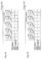
- FIG. 7A is an illustration showing motion vectors in direct mode, and specifically shows the case where the block a in the picture B7 is coded in direct mode.
- a motion vector c which has been used for coding the block b in the picture P9, is utilized.
- the block b is co-located with the block a, and the picture P9 is a backward reference picture of the picture B7.
- the motion vector c is stored in the motion vector storage unit 116.
- the block a is bi-predicted from the forward reference picture P5 and the backward reference picture P9 using vectors obtained utilizing the motion vector c.
- the motion vector d and the motion vector e are used for the picture P5 and the picture P9 respectively for coding the block a.
- the motion vector d MVF and the motion vector e MVB are respectively calculated by Equation 1 and Equation 2.
- the temporal distance between the pictures can be determined based on the information indicating the display order (position) given to the respective pictures or the difference specified by the information.
- MVF MV ⁇ TRF / TRD
- MVB TRF - TRD ⁇ MV / TRD
- the mode selection unit 109 outputs the determined coding mode to the bit stream generation unit 104. If the coding mode determined by the mode selection unit 109 is inter picture prediction coding, the motion vectors used for the inter picture prediction coding is outputted to the bit stream generation unit 104 and further stored in the motion vector storage unit 116. When the direct mode is selected, the motion vectors which are calculated according to Equation 1 and Equation 2 and used for direct mode are stored in the motion vector storage unit 116.
- the mode selection unit 109 also generates predictive image data based on the determined coding mode for outputting to the difference calculation unit 102 and the addition unit 106, although it does not output the predictive image data if it selects the intra picture coding.
- the mode selection unit 109 controls the switches 111 and 112 to connect to "a" side and "c" side respectively, and when selecting the inter picture prediction coding or direct mode, it controls the switches 111 and 112 to connect to "b" side and "d” side respectively.
- the mode selection unit 109 selects the inter picture prediction coding or the direct mode.
- the difference calculation unit 102 receives the image data of the macroblock of the picture B7 read out from the reordering memory 101 and the predictive image data outputted from the mode selection unit 109. The difference calculation unit 102 calculates the difference between the image data of the macroblock of the picture B7 and the predictive image data, and generates the residual error image data for outputting to the residual error coding unit 103.
- the residual error coding unit 103 performs coding processing such as frequency transform and quantization on the inputted residual error image data and thus generates the coded data for outputting to the bit stream generation unit 104 and the residual error decoding unit 105.
- the bit stream generation unit 104 performs variable length coding or the like on the inputted coded data, and further adds information such as motion vectors and a coding mode and so on to that data for generating and outputting a bit stream.
- the residual error decoding unit 105 performs decoding processing such as inverse quantization and inverse frequency transform on the inputted coded data and generates the decoded differential image data for outputting to the addition unit 106.
- the addition unit 106 adds the decoded differential image data and the predictive image data inputted by the mode selection unit 109 for generating the decoded image data, and stores it in the reference picture memory 107.
- the picture B6 is a B-picture
- B6 is coded using inter picture prediction with reference to two previously processed pictures located earlier or later than B6 in display order.
- the B-picture B6 refers to the picture P5 as a forward reference picture and the picture B7 as a backward reference picture, as described above. Since the picture B6 is not used as a reference picture for coding other pictures, the coding control unit 110 controls the switch 113 to be ON and the switches 114 and 115 to be OFF, which causes the macroblock of the picture B6 read out from the reordering memory 101 to be inputted to the motion vector estimation unit 108, the mode selection unit 109 and the difference calculation unit 102.
- the motion vector estimation unit 108 uses the decoded picture data of the picture P5 and the decoded picture data of the picture B7 which are stored in the reference picture memory 107 as a forward reference picture and a backward reference picture respectively. Using the decoded picture data of the picture P5 and the decoded picture data of the picture B7 which are stored in the reference picture memory 107 as a forward reference picture and a backward reference picture respectively, the motion vector estimation unit 108 estimates the forward motion vector and the backward motion vector for the macroblock in the picture B6. And the motion vector estimation unit 108 outputs the estimated motion vectors to the mode selection unit 109.
- the mode selection unit 109 determines the coding mode for the macroblock in the picture B6 using the motion vectors estimated by the motion vector estimation unit 108.
- Fig. 7B is an illustration showing motion vectors in direct mode, and specifically showing the case where the block a in the picture B6 is coded in direct mode.
- a motion vector c which has been used for coding a block b in the picture B7 is utilized.
- the block b is co-located with the block a, and the picture B7 is a backward reference picture of the picture B6.
- the block b is coded by forward reference only or bi-predictive reference and the forward motion vector of the block b is the motion vector c.
- the motion vector c is stored in the motion vector storage unit 116.
- the block a is bi-predicted from the forward reference picture P5 and the backward reference picture B7 using motion vectors generated utilizing the motion vector c. For example, if a method of generating motion vectors parallel to the motion vector c is used, as is the case of the above-mentioned picture B7, the motion vector d and the motion vector e are used for the picture P5 and the picture B7 respectively for coding the block a.
- the motion vector d MVF and the motion vector e MVB are respectively calculated by above-mentioned Equation 1 and Equation 2.
- the temporal distance between the pictures can be determined based on the information indicating display order of the pictures or the difference specified by the information, for instance.
- the motion vector which has been used for coding the block b in the picture B7
- the block b is co-located with the block a
- the picture B7 is a backward reference picture for the picture B6.
- the block b has been coded in direct mode and the forward motion vector which has been substantially used for coding the block b is the motion vector c.
- the motion vector c is obtained by scaling the motion vector used for coding a block i, co-located with the block b, in the picture P9 that is the backward reference picture for the picture B7.
- the motion vector c stored in the motion vector storage unit 116 is used, or the motion vector c is obtained by reading out from the motion vector storage unit 116 the motion vector of the block i in the picture P9 which has been used for coding the block b in direct mode and calculating based on that motion vector.
- the motion vector which is obtained by scaling for coding the block b in the picture B7 in direct mode is stored in the motion vector storage unit 116, only the forward motion vector needs to be stored.
- the block a is bi-predicted from the forward reference picture P5 and the backward reference picture B7 using the motion vectors generated utilizing the motion vector c.
- motion vectors used for coding the block a are the motion vector d and the motion vector e for the picture P5 and the picture B7 respectively.
- the forward motion vector d MVF and the backward motion vector e MVB of the block a are respectively calculated by above-mentioned Equation 1 and Equation 2, as in the case of the first example.
- Fig. 7C is an illustration showing motion vectors in direct mode, and specifically showing the case where the block a in the picture B6 is coded in direct mode.
- the motion vector which has been used for coding the block b in the picture B7 is utilized.
- the picture B7 is a backward reference picture for the picture B6, and the block b in the picture B7 is co-located with the block a in the picture B6.
- the block b has been coded using a backward motion vector only and the backward motion vector used for coding the block b is a motion vector f.
- the motion vector f is assumed to be stored in the motion vector storage unit 116.
- the block a is bi-predicted from the forward reference picture P5 and the backward reference picture B7 using motion vectors generated utilizing the motion vector f.
- motion vectors used for coding the block a are the motion vector g and the motion vector h for the picture P5 and the picture B7 respectively.
- the motion vector g MVF and the motion vector h MVB are respectively calculated by Equation 3 and Equation 4.
- MVF - TRF ⁇ MV / TRD
- MVB TRB ⁇ MV / TRD
- FIG. 7D is an illustration showing motion vectors in direct mode, and specifically showing the case where the block a in the picture B6 is coded in direct mode.
- the motion vector which has been used for coding the block b in the picture B7 is utilized.
- the picture B7 is the backward reference picture for the picture B6, and the block b is co-located with the block a in the picture B6.
- the block b has been coded using the backward motion vector only, as is the case of the third example, and the backward motion vector used for coding the block b is the motion vector f.
- the motion vector f is assumed to be stored in the motion vector storage unit 116.
- the block a is bi-predicted from the reference picture P9 which is referred to by the motion vector f and the backward reference picture B7 using motion vectors generated utilizing the motion vector f.
- motion vectors used for coding the block a are the motion vector g and the motion vector h for the picture P9 and the picture B7 respectively.
- the motion vector g MVF and the motion vector h MVB are respectively calculated by Equation 1 and Equation 2.
- Fig. 8A is an illustration showing motion vectors in direct mode, and specifically showing the case where the block a of the picture B6 is coded in direct mode.
- bi-predictive reference is performed for motion compensation, using the picture P5 as a forward reference picture and the picture B7 as a backward reference picture.
- FIG. 8B is an illustration showing motion vectors in direct mode, and specifically showing the case where the block a in the picture B6 is coded in direct mode.
- the motion vector g which has been used for coding the block f in the picture P9 is utilized.
- the picture P9 is located later than the picture B6, and the block f is co-located with the block a in the picture B6.
- the motion vector g is stored in the motion vector storage unit 116.
- the block a is bi-predicted from the forward reference picture P5 and the backward reference picture B7 using motion vectors generated utilizing the motion vector g.
- motion vectors used for coding the block a are the motion vector h and the motion vector i for the picture P5 and the picture B7 respectively for coding the block a.
- the motion vector h MVF and the motion vector i MVB are respectively calculated by Equation 1 and Equation 5.
- MVB - TRB ⁇ MV / TRD
- Fig. 8C is an illustration showing motion vectors in direct mode, and specifically showing the case where the block a in the picture B6 is coded in direct mode.
- This example shows the case where the above-mentioned assignment of relative indices to the picture numbers is changed (remapped) and the picture P9 is a backward reference picture.
- the motion vector g which has been used for coding the block f in the picture P9 is utilized.
- the picture P9 is the backward reference picture for the picture B7, and the block f is co-located with the block a in the picture B6.
- the motion vector g is stored in the motion vector storage unit 116.
- the block a is bi-predicted from the forward reference picture P5 and the backward reference picture P9 using motion vectors generated utilizing the motion vector g.
- motion vectors used for coding the block a are the motion vector h and the motion vector i for the picture P5 and the picture P9 respectively.
- the motion vector h MVF and the motion vector i MVB are respectively calculated by Equation 1 and Equation 2.
- the motion vector of the previously coded picture can be scaled even if the relative indices to the picture numbers are remapped, and when the direct mode is selected, there is no need to transmit the motion vector information.
- the block in the backward reference picture for the picture B6 which is co-located with the block a is coded by the forward reference only, bi-predictive reference, or direct mode.
- this forward motion vector is scaled, and the block a is coded in direct mode, as is the case of the above-mentioned first, second or seventh example.
- this backward motion vector is scaled, and the block a is coded in direct mode, as is the case of the above-mentioned third or fourth example.
- the mode selection unit 109 outputs the determined coding mode to the bit stream generation unit 104. Also, the mode selection unit 109 generates predictive image data based on the determined coding mode and outputs it to the difference calculation unit 102. However, if selecting intra picture coding, the mode selection unit 109 does not output predictive image data.
- the mode selection unit 109 controls the switches 111 and 112 so as to be connected to "a" side and "c" side respectively if selecting intra picture coding, and controls the switches 111 and 112 so as to be connected to "b" side and "d” side if selecting inter picture prediction coding or a direct mode.
- the mode selection unit 109 outputs the motion vectors used for the inter picture prediction coding to the bit stream generation unit 104. Since the picture B6 is not used as a reference picture for coding other pictures, there is no need to store the motion vectors used for the inter picture prediction coding in the motion vector storage unit 116. The case will be explained below where the mode selection unit 109 selects the inter picture prediction coding or the direct mode.
- the difference calculation unit 102 receives the image data of the macroblock in the picture B6 read out from the reordering memory 101 and the predictive image data outputted from the mode selection unit 109.
- the difference calculation unit 102 calculates the difference between the image data of the macroblock in the picture B6 and the predictive image data and generates the residual error image data for outputting to the residual error coding unit 103.
- the residual error coding unit 103 performs coding processing such as frequency transform and quantization on the inputted residual error image data, and thus generates the coded data for outputting to the bit stream generation unit 104.
- the bit stream generation unit 104 performs variable length coding or the like on the inputted coded data, further adds information such as motion vectors and a coding mode and so on to the data, and generates the bit stream for outputting.
- the picture B6 That is the completion of coding one macroblock in the picture B6. According to the same processing, the remaining macroblocks in the picture B6 are coded. And after all the macroblocks in the picture B6 are coded, the picture B8 is coded.
- a picture B8 is a B-picture
- inter picture prediction coding is performed for the picture B8 with reference to two previously processed pictures located earlier or later than B6 in display order.
- the B-picture B8 refers to the picture B7 as a forward reference picture and the picture P9 as a backward reference picture, as described above. Since the picture B8 is not used as a reference picture for coding other pictures, the coding control unit 110 controls the switch 113 to be ON and the switches 114 and 115 to be OFF, which causes the macroblocks in the picture B8 read out from the reordering memory 101 to be inputted to the motion vector estimation unit 108, the mode selection unit 109 and the difference calculation unit 102.
- the motion vector estimation unit 108 uses the decoded picture data of the picture B7 and the decoded picture data of the picture P9 which are stored in the reference picture memory 107 as a forward reference picture and a backward reference picture respectively. Using the decoded picture data of the picture B7 and the decoded picture data of the picture P9 which are stored in the reference picture memory 107 as a forward reference picture and a backward reference picture respectively, the motion vector estimation unit 108 estimates the forward motion vector and the backward motion vector for the macroblock in the picture B8. And the motion vector estimation unit 108 outputs the estimated motion vectors to the mode selection unit 109.
- the mode selection unit 109 determines the coding mode for the macroblock in the picture B8 using the motion vectors estimated by the motion vector estimation unit 108.
- Fig. 8D is an illustration showing motion vectors in direct mode, and specifically showing the case where a block a in the picture B8 is coded in direct mode.
- a motion vector c which has been used for coding a block b in the backward picture P9 is utilized.
- the reference picture P9 is located later than the picture B8, and the block b in the picture P9 is co-located with the block a.
- the block b has been coded by forward reference and the forward motion vector for the block b is the motion vector c.
- the motion vector c is stored in the motion vector storage unit 116.
- the block a is bi-predicted from the forward reference picture B7 and the backward reference picture P9 using motion vectors generated utilizing the motion vector c. For example, if a method of generating motion vectors parallel to the motion vector c is used, as is the case of the above-mentioned picture B6, the motion vector d and the motion vector e are used for the picture B7 and the picture P9 respectively for coding the block a.
- the motion vector d MVF and the motion vector e MVB are respectively calculated by Equation 1 and Equation 5.
- the mode selection unit 109 outputs the determined coding mode to the bit stream generation unit 104. Also, the mode selection unit 109 generates predictive image data based on the determined coding mode and outputs it to the difference calculation unit 102. However, if selecting intra picture coding, the mode selection unit 109 does not output predictive image data.
- the mode selection unit 109 controls the switches 111 and 112 so as to be connected to "a" side and "c" side respectively if selecting intra picture coding, and controls the switches 111 and 112 so as to be connected to "b" side and "d” side if selecting inter picture prediction coding or direct mode.
- the mode selection unit 109 outputs the motion vectors used for the inter picture prediction coding to the bit stream generation unit 104. Since the picture B8 is not be used as a reference picture for coding other pictures, there is no need to store the motion vectors used for the inter picture prediction coding in the motion vector storage unit 116. The case will be explained below where the mode selection unit 109 selects the inter picture prediction coding or direct mode.
- the difference calculation unit 102 receives the image data of the macroblock in the picture B8 read out from the reordering memory 101 and the predictive image data outputted from the mode selection unit 109.
- the difference calculation unit 102 calculates the difference between the image data of the macroblock in the picture B8 and the predictive image data and generates the residual error image data for outputting to the residual error coding unit 103.
- the residual error coding unit 103 performs coding processing such as frequency transform and quantization on the inputted residual error image data and thus generates the coded data for outputting to the bit stream generation unit 104.
- the bit stream generation unit 104 performs variable length coding or the like on the inputted coded data, further adds information such as motion vectors and a coding mode and so on to the data, and generates the bit stream for outputting.
- the moving picture coding method according to the present invention has been explained taking the case where the picture prediction structure as shown in Fig. 6A is used as an example.
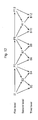
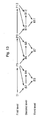
- Fig. 12 is an illustration showing this picture prediction structure hierarchically.
- arrows indicate prediction relations, in which the pictures pointed by the arrows refer to the pictures located at the origins of the arrows.
- the coding order is determined by giving a top priority to the pictures which are farthest from the previously processed pictures in display order, as shown in Fig. 12 .
- the picture farthest from an I-picture or a P-picture is that located in the center of the consecutive B-pictures. Therefore, if the picture P5 and P9 have been coded, the picture B7 is to be coded next. And if the pictures P5, B7 and P9 have been coded, the pictures B6 and B8 are to be coded next.
- the moving picture coding method according to the present invention can be used for other picture prediction structures than those as shown in Fig. 6 and Fig. 12 , so as to produce the effects of the present invention.
- Figs. 9 ⁇ 11 show the examples of other picture prediction structures.
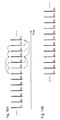
- Fig. 9 shows the case where 3 B-pictures are located between I-pictures and P-pictures and the B-picture closest from the previously processed picture is selected for coding first.
- Fig. 9A is a diagram showing prediction relations between respective pictures arranged in display order
- Fig. 9B is a diagram showing the sequence of pictures reordered in coding order (a bit stream).
- Fig. 13 is a hierarchical diagram of the picture prediction structure corresponding to Fig. 9A .
- the pictures closest in display order from the previously processed pictures are coded first, as shown in Fig. 13 . For example, if the pictures P5 and P9 have been coded, the pictures B6 and B8 are to be coded next. If the pictures P5, B6, B8 and P9 have been coded, the picture B7 is to be coded next.
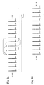
- Fig. 10 shows the case where 5 B-pictures are located between I-pictures and P-pictures and the B-picture which is farthest from the previously processed picture is selected for coding first.
- Fig. 10A is a diagram showing prediction relations between respective pictures arranged in display order
- Fig. 10B is a diagram showing the sequence of pictures reordered in coding order (a bit stream).
- Fig. 14 is a hierarchical diagram of the picture prediction structure corresponding to Fig. 10A . In the picture prediction structure as shown in Fig. 10A , the coding order is determined by giving a top priority to the pictures farthest in display order from the previously processed pictures, as shown in Fig. 14 .
- the picture farthest from an I-picture or a P-picture is the B-picture in the center of the consecutive B-pictures. Therefore, if the pictures P7 and P13 have been coded, the picture B10 is to be coded next. If the pictures P7, B10 and P13 have been coded, the pictures B8, B9, B11 and B12 are to be coded next.
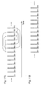
- Fig. 11 shows the case where 5 B-pictures are located between I-pictures and P-pictures and the B-picture which is closest from the previously processed picture is selected for coding first.
- Fig. 11A is a diagram showing prediction relations between respective pictures arranged in display order
- Fig. 11B is a diagram showing the sequence of pictures reordered in coding order (a bit stream).
- Fig. 15 is a hierarchical diagram of the picture prediction structure corresponding to Fig. 11A . In the picture prediction structure as shown in Fig. 11A , the pictures closest in display order from the previously processed pictures are coded first, as shown in Fig. 15 .
- the pictures B8 and B12 are to be coded next. If the pictures P5, B8, B12 and P9 have been coded, the pictures B9 and B11 are to be coded next. Furthermore, if the pictures P5, B8, B9, B11, B12 and P9 have been coded, the picture B10 is to be coded next.
- the moving picture coding method of the present invention when inter picture prediction coding is performed on a plurality of B-pictures located between I-pictures and P-pictures using bi-predictive reference, they are coded in another order than display order.
- the pictures located as close to the current picture as possible in display order are used as forward and backward pictures.
- a B-picture is also used if it is available.
- the picture farthest from the previously processed picture is to be coded first.
- the picture closest from the previously processed picture is to be coded first.
- above-mentioned operation enables to use a picture closer to a current B-picture in display order as a reference picture for coding it. Prediction efficiency is thus increased for motion compensation and coding efficiency is increased.
- a motion vector obtained by scaling the forward motion vector of the backward reference B-picture is used as a motion vector in direct mode.
- a motion vector obtained by scaling the forward motion vector substantially used in direct mode is used as a motion vector in direct mode.
- motion vectors obtained by scaling the backward motion vector of the block is used as motion vectors in direct mode.
- motion vectors obtained by scaling the backward motion vector used for that coding, with reference to the picture referred to by this backward motion vector and the backward reference picture are used as motion vectors in direct mode.
- a motion vector obtained by scaling the forward motion vector which has been used for coding the co-located block in the later P-picture is used as a motion vector in direct mode.
- motion vectors obtained by scaling that forward motion vector are used as motion vectors in direct mode.
- a motion vector of a previously coded picture can be scaled even if assignment of relative indices to picture numbers is changed, and there is no need to transmit motion vector information.
- one of intra picture coding, inter picture prediction coding using motion vectors and inter picture prediction coding without using motion vectors is selected as a coding mode for P-pictures
- one of intra picture coding, inter picture prediction coding using a forward motion vector, inter picture prediction coding using a backward motion vector, inter picture prediction coding using a bi-predictive motion vectors and direct mode is selected for B-pictures, but other coding mode may be used.
- a P-picture is coded with reference to one previously coded I or P-picture which is located temporally earlier or later in display order than the current P-picture
- a B-picture is coded with reference to two previously processed neighboring pictures which are located earlier or later in display order than the current B-picture, respectively.
- the P-picture may be coded with reference to at most one picture for each block from among a plurality of previously coded I or P pictures as candidate reference pictures
- the B-picture may be coded with reference to at most two pictures for each block from among a plurality of previously coded neighboring pictures which are located temporally earlier or later in display order as candidate reference pictures.
- the mode selection unit 109 may store both forward and backward motion vectors or only a forward motion vector, if a current block is coded by bi-predictive reference or in direct mode. If it stores only the forward motion vector, the volume stored in the motion vector storage unit 116 can be reduced.
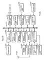
- Fig. 16 is a block diagram showing a structure of a moving picture decoding apparatus using a moving picture decoding method according to an embodiment of the present invention.
- the moving picture decoding apparatus includes a bit stream analysis unit 1401, a residual error decoding unit 1402, a mode decoding unit 1403, a frame memory control unit 1404, a motion compensation decoding unit 1405, a motion vector storage unit 1406, a frame memory 1407, an addition unit 1408 and switches 1409 and 1410.
- the bit stream analysis unit 1401 extracts various types of data such as coding mode information and motion vector information from the inputted bit stream.
- the residual error decoding unit 1402 decodes the residual error coded data inputted from the bit stream analysis unit 1401 and generates residual error image data.
- the mode decoding unit 1403 controls the switches 1409 and 1410 with reference to the coding mode information extracted from the bit stream.
- the frame memory control unit 1404 outputs the decoded picture data stored in the frame memory 1407 as output pictures based on the information indicating the display order of the pictures inputted from the bit stream analysis unit 1401.
- the motion compensation decoding unit 1405 decodes the information of the reference picture numbers and the motion vectors, and obtains motion compensation image data from the frame memory 1407 based on the decoded reference picture numbers and motion vectors.
- the motion vector storage unit 1406 stores motion vectors.
- the addition unit 1408 adds the residual error coded data inputted from the residual error decoding unit 1402 and the motion compensation image data inputted from the motion compensation decoding unit 1405 for generating the decoded image data.
- the frame memory 1407 stores the generated decoded image data.
- a P-picture refers to one previously processed neighboring I or P-picture which is located earlier or later than the current P-picture in display order
- a B-picture refers to two previously coded neighboring pictures which are located earlier or later than the current B-picture in display order.
- the pictures in the bit stream are arranged in the order as shown in Fig. 6B .
- Decoding processing of pictures P9, B7, B6 and B8 will be explained below in this order.
- the bit stream of the picture P9 is inputted to the bit stream analysis unit 1401.
- the bit stream analysis unit 1401 extracts various types of data from the inputted bit stream.
- various types of data mean mode selection information, motion vector information and others.
- the extracted mode selection information is outputted to the mode decoding unit 1403.
- the extracted motion vector information is outputted to the motion compensation decoding unit 1405.
- the residual error coded data is outputted to the residual error decoding unit 1402.
- the mode decoding unit 1403 controls the switches 1409 and 1410 with reference to the coding mode selection information extracted from the bit stream. If intra picture coding is selected as a coding mode, the mode decoding unit 1403 controls the switches 1409 and 1410 so as to be connected to "a" side and "c" side respectively. If inter picture prediction coding is selected as a coding mode, the mode decoding unit 1403 controls the switches 1409 and 1410 so as to be connected to "b" side and "d" side respectively.
- the mode decoding unit 1403 also outputs the coding mode selection information to the motion compensation decoding unit 1405. The case where the inter picture prediction coding is selected as a coding mode will be explained below.
- the residual error decoding unit 1402 decodes the inputted residual error coded data to generate residual error image data.
- the residual error decoding unit 1402 outputs the generated residual error image data to the switch 1409. Since the switch 1409 is connected to "b" side, the residual error image data is outputted to the addition unit 1408.
- the motion compensation decoding unit 1405 obtains motion compensation image data from the frame memory 1407 based on the inputted motion vector information and the like.
- the picture P9 has been coded with reference to the picture P5, and the picture P5 has been already decoded and stored in the frame memory 1407. So, the motion compensation decoding unit 1405 obtains the motion compensation image data from the picture data of the picture P5 stored in the frame memory 1407, based on the motion vector information.
- the motion compensation image data generated in this manner is outputted to the addition unit 1408.
- the motion compensation decoding unit 1405 stores the motion vector information in the motion vector storage unit 1406.
- the addition unit 1408 adds the inputted residual error image data and motion compensation image data to generate decoded image data.
- the generated decoded image data is outputted to the frame memory 1407 via the switch 1410.
- the motion compensation decoding unit 1405 generates motion compensation image data based on the inputted motion vector information and the like.
- the picture B7 is coded with reference to the picture P5 as a forward reference picture and the picture P9 as a backward reference picture, and these pictures P5 and P9 have already been decoded and stored in the frame memory 1407.
- the motion compensation decoding unit 1405 obtains the forward reference picture data from the frame memory 1407 based on the forward motion vector information. It also obtains the backward reference picture data from the frame memory 1407 based on the backward motion vector information. Then, the motion compensation decoding unit 1405 averages the forward and backward reference picture data to generate motion compensation image data.
- the motion compensation decoding unit 1405 When direct mode is selected as a coding mode, the motion compensation decoding unit 1405 obtains the motion vector of the picture P9 stored in the motion vector storage unit 1406. Using this motion vector, the motion compensation decoding unit 1405 obtains the forward and backward reference picture data from the frame memory 1407. Then, the motion compensation decoding unit 1405 averages the forward and backward reference picture data to generate motion compensation image data.
- the motion vector of the block b is the motion vector c, which refers to the picture P5.
- the motion vector d which is obtained utilizing the motion vector c and refers to the picture P5 is used as a forward motion vector
- the motion vector e which is obtained utilizing the motion vector c and refers to the picture P9 is used as a backward motion vector.
- a method of utilizing the motion vector c there is a method of generating motion vectors parallel to the motion vector c.
- the motion compensation image data is obtained by averaging the forward and backward reference data obtained based on these motion vectors.
- the motion vector d MVF and the motion vector e MVB are respectively calculated by Equation 1 and Equation 2, where MVF and MVB represent horizontal and vertical components of the motion vectors respectively.
- the temporal distance between the pictures can be determined based on the information indicating the display order (position) given to respective pictures or the difference specified by the information.
- the motion compensation image data generated in this manner is outputted to the addition unit 1408.
- the motion compensation decoding unit 1405 stores the motion vector information in the motion vector storage unit 1406.
- the addition unit 1408 adds the inputted residual error image data and the motion compensation image data to generate decoded image data.
- the generated decoded image data is outputted to the frame memory 1407 via the switch 1410.
- the motion compensation decoding unit 1405 generates motion compensation image data based on the inputted motion vector information and the like.
- the picture B6 has been coded with reference to the picture P5 as a forward reference picture and the picture B7 as a backward reference picture, and these pictures P5 and B7 have been already decoded and stored in the frame memory 1407.
- the motion compensation decoding unit 1405 obtains the forward reference picture data from the frame memory 1407 based on the forward motion vector information. It also obtains the backward reference picture data from the frame memory 1407 based on the backward motion vector information. Then, the motion compensation decoding unit 1405 averages the forward and backward reference picture data to generate motion compensation image data.
- the motion compensation decoding unit 1405 When the direct mode is selected as a coding mode, the motion compensation decoding unit 1405 obtains the motion vector of the picture B7 stored in the motion vector storage unit 1406. Using this motion vector, the motion compensation decoding unit 1405 obtains the forward and backward reference picture data from the frame memory 1407. Then, the motion compensation decoding unit 1405 averages the forward and backward reference picture data to generate motion compensation image data.
- the first example of the case where the direct mode is selected as a coding mode will be explained with reference to Fig. 7B again.
- the block a in the picture B6 is to be decoded and the block b in the picture B7 is co-located with the block a.
- the block b has been coded by forward reference inter picture prediction or bi-predictive reference inter picture prediction, and the forward motion vector of the block b is the motion vector c, which refers to the picture P5.
- the motion vector d which is obtained utilizing the motion vector c and refers to the picture P5 is used as a forward motion vector
- the motion vector e which is obtained utilizing the motion vector c and refers to the picture B7 is used as a backward motion vector.
- a method of utilizing the motion vector c there is a method of generating motion vectors parallel to the motion vector c.
- the motion compensation image data is obtained by averaging the forward and backward reference picture data obtained based on these motion vectors d and e.
- the motion vector d MVF and the motion vector e MVB are respectively calculated by Equation 1 and Equation 2.
- the temporal distance between pictures may be determined based on the information indicating the display order (position) of the pictures or the difference specified by the information.
- predetermined values for respective pictures may be used as the values of TRD and TRF. These predetermined values may be described in the bit stream as header information.
- the motion vector which has been used for decoding the block b in the picture B7 is utilized.
- the picture B7 is the backward reference picture for the current picture B6, and the block b is co-located with the block a in the picture B6.
- the block b has been coded in direct mode and the motion vector c has been substantially used as a forward motion vector for that coding.
- the motion vector c stored in the motion vector storage unit 1406 may be used, or it is calculated by reading out from the motion vector storage unit 1406 the motion vector of the picture P9 which has been used for coding the block b in direct mode, and then scaling that motion vector.
- the motion compensation decoding unit 1405 needs to store only the forward motion vector out of the two motion vectors obtained by scaling for decoding the block b in the picture B7 in direct mode.
- the motion vector d which is generated utilizing the motion vector c and refers to the picture P5 is used as a forward motion vector
- the motion vector e which is generated utilizing the motion vector c and refers to the picture B7 is used as a backward motion vector.
- a method of utilizing the motion vector c there is a method of generating motion vectors parallel to the motion vector c.
- the motion compensation image data is obtained by averaging the forward and backward reference picture data obtained based on these motion vectors d and e.
- the motion vector d MVF and the motion vector e MVB are respectively calculated by Equation 1 and Equation 2, as is the case of the first example of the direct mode.
- the block a in the picture B6 is to be decoded, and the block b in the picture B7 is co-located with the block a.
- the block b has been coded by backward reference prediction, and the backward motion vector of the block b is a motion vector f, which refers to the picture P9.
- the motion vector g which is obtained utilizing the motion vector f and refers to the picture P5 is used as a forward motion vector
- the motion vector h which is obtained utilizing the motion vector f and refers to the picture B7 is used as a backward motion vector.
- the motion compensation image data is obtained by averaging the forward and backward reference picture data obtained based on these motion vectors g and h.
- the motion vector g MVF and the motion vector h MVB are respectively calculated by Equation 3 and Equation 4.
- the block a in the picture B6 is to be decoded, and the block b in the picture B7 is co-located with the block a.
- the block b has been coded by backward reference prediction as is the case of the third example, and the backward motion vector of the block b is a motion vector f, which refers to the picture P9.
- the motion vector g which is obtained utilizing the motion vector f and refers to the picture P9 is used as a forward motion vector
- the motion vector h which is obtained utilizing the motion vector f and refers to the picture B7 is used as a backward motion vector.
- the motion compensation image data is obtained by averaging the forward and backward reference picture data obtained based on these motion vectors g and h.
- the motion vector g MVF and the motion vector h MVB are respectively calculated by Equation 1 and Equation 2.
- the fifth example of the case where the direct mode is selected as a coding mode will be explained with reference to Fig. 8A again.
- the motion vector is set to zero "0"
- motion compensation is performed by bi-predictive reference using the picture P5 as a forward reference picture and the picture B7 as a backward reference picture.
- the sixth example of the case where the direct mode is selected as a coding mode will be explained with reference to Fig. 8B again.
- the motion vector g which has been used for decoding the block f in the P-picture P9 is utilized.
- the picture P9 is located later than the current picture B6, and the block f is co-located with the block a.
- the motion vector g is stored in the motion vector storage unit 1406.
- the block a is bi-predicted from the forward reference picture P5 and the backward reference picture B7 using the motion vectors which are obtained utilizing the motion vector g.
- the motion vector h and the motion vector i are used for the picture P5 and the picture B7 respectively for obtaining the motion compensation image data of the block a.
- the motion vector h MVF and the motion vector i MVB are respectively calculated by Equation 1 and Equation 5.
- the seventh example of the case where the direct mode is selected as a coding mode will be explained with reference to Fig. 8C again.
- a block a in the picture B6 is decoded in direct mode.
- the assignment of relative indices to the above-mentioned picture numbers is changed (remapped) and the picture P9 is the backward reference picture.
- the motion vector g which has been used for coding the block f in the picture P9 is utilized.
- the picture P9 is the backward reference picture for the picture B6, and the block f is co-located with the block a in the picture B6.
- the motion vector g is stored in the motion vector storage unit 1406.
- the block a is bi-predicted from the forward reference picture P5 and the backward reference picture P9 using motion vectors generated utilizing the motion vector g.
- the motion vector h and the motion vector i are used for the picture P5 and the picture P9 respectively for obtaining the motion compensation image data of the block a.
- the motion vector h MVF and the motion vector i MVB are respectively calculated by Equation 1 and Equation 2.
- the motion compensation image data generated as above is outputted to the addition unit 1408.
- the addition unit 1408 adds the inputted residual error image data and the motion compensation image data to generate decoded image data.
- the generated decoded image data is outputted to the frame memory 1407 via the switch 1410.
- the motion compensation decoding unit 1405 generates motion compensation image data based on the inputted motion vector information and the like.
- the picture B8 has been coded with reference to the picture B7 as a forward reference picture and the picture P9 as a backward reference picture, and these pictures B7 and P9 have been already decoded and stored in the frame memory 1407.
- the motion compensation decoding unit 1405 obtains the forward reference image data from the frame memory 1407 based on the forward motion vector information. It also obtains the backward reference image data from the frame memory 1407 based on the backward motion vector information. Then, the motion compensation decoding unit 1405 averages the forward and backward reference image data to generate motion compensation image data.
- the motion compensation decoding unit 1405 When direct mode is selected as a coding mode, the motion compensation decoding unit 1405 obtains the motion vector of the picture P9 stored in the motion vector storage unit 1406. Using this motion vector, the motion compensation decoding unit 1405 obtains the forward and backward reference image data from the frame memory 1407. Then, the motion compensation decoding unit 1405 averages the forward and backward reference picture data to generate motion compensation image data.
- the forward motion vector of the block b is the motion vector c, which refers to the picture P5.
- the motion vector d which is generated utilizing the motion vector c and refers to the picture B7 is used as a forward motion vector
- the motion vector e which is generated utilizing the motion vector c and refers to the picture P9 is used as a backward motion vector.
- the motion compensation image data is obtained by averaging the forward and backward reference image data obtained based on these motion vectors d and e.
- the motion vector d MVF and the motion vector e MVB are respectively calculated by Equation 1 and Equation 5.
- the motion compensation image data generated in this manner is outputted to the addition unit 1408.
- the addition unit 1408 adds the inputted residual error image data and the motion compensation image data to generate decoded image data.
- the generated decoded image data is outputted to the frame memory 1407 via the switch 1410.
- the frame memory control unit 1404 reorders the picture data of the pictures stored in the frame memory 1407 in time order as shown in Fig. 6A for outputting as output pictures.
- a B-picture which has been coded by inter picture bi-prediction is decoded using previously decoded pictures which are located close in display order as forward and backward reference pictures.
- reference image data is obtained from previously decoded image data to obtain motion compensation image data, with reference to a motion vector of a previously decoded backward reference picture stored in the motion vector storage unit 1406.
- the direct mode has been explained.
- one method which is uniquely determined for every macroblock or block based on the decoding method of a co-located block in a backward reference picture, may be used, or a plurality of different methods may be used for every macroblock or block by switching them.
- the macroblock or the block is decoded using information described in a bit stream, indicating which type of direct mode has been used.
- the operation of the motion compensation decoding unit 1405 depends upon the information. For example, when this information is added for every block of motion compensation, the mode decoding unit 1403 determines which type of direct mode is used for coding and delivers it to the motion compensation decoding unit 1405.
- the motion compensation decoding unit 1405 performs decoding processing using the decoding method as explained in the present embodiment depending upon the delivered type of direct mode.
- the P-picture may be coded with reference to at most one picture for each block from among a plurality of previously coded I or P pictures which are located temporally earlier or later in display order as candidate reference pictures
- the B-picture may be coded with reference to at most two pictures for each block from among a plurality of previously coded neighboring pictures which are located temporally earlier or later in display order as candidate reference pictures.
- the motion compensation decoding unit 1405 may store both forward and backward motion vectors, or store only the forward motion vector, if a current block is coded by bi-predictive reference or in direct mode. If only the forward motion vector is stored, the memory volume of the motion vector storage unit 1406 can be reduced.
- Fig. 17 is an illustration showing the case where the processing is performed in a computer system using a flexible disk which stores the moving picture coding method or the moving picture decoding method of the above embodiments.
- Fig. 17B shows a front view and a cross-sectional view of an appearance of a flexible disk, and the flexible disk itself
- Fig. 17A shows an example of a physical format of a flexible disk as a recording medium body.
- the flexible disk FD is contained in a case F, and a plurality of tracks Tr are formed concentrically on the surface of the disk in the radius direction from the periphery and each track is divided into 16 sectors Se in the angular direction. Therefore, as for the flexible disk storing the above-mentioned program, the moving picture coding method as the program is recorded in an area allocated for it on the flexible disk FD.
- Fig. 17C shows the structure for recording and reproducing the program on and from the flexible disk FD.
- the program is recorded on the flexible disk FD
- the moving picture coding method or the moving picture decoding method as a program is written in the flexible disk from the computer system Cs via a flexible disk drive.
- the moving picture coding method is constructed in the computer system by the program on the flexible disk, the program is read out from the flexible disk drive and transferred to the computer system.
- the above explanation is made on the assumption that a recording medium is a flexible disk, but the same processing can also be performed using an optical disk.
- the recording medium is not limited to a flexible disk and an optical disk, but any other medium such as an IC card and a ROM cassette capable of recording a program can be used.
- Fig. 18 is a block diagram showing the overall configuration of a content supply system ex100 for realizing content distribution service.
- the area for providing communication service is divided into cells of desired size, and base stations ex107 ⁇ ex110 which are fixed wireless stations are placed in respective cells.
- devices such as a computer ex111, a PDA (personal digital assistant) ex112, a camera ex113, a mobile phone ex114 and a camera-equipped mobile phone ex115 are connected to the Internet ex 101 via an Internet service provider ex102, a telephone network ex104 and base stations ex107 ⁇ ex110.
- PDA personal digital assistant
- the content supply system ex100 is not limited to the configuration as shown in Fig. 18 , and a combination of any of them may be connected. Also, each device may be connected directly to the telephone network ex104, not through the base stations ex107 ⁇ ex110.
- the camera ex113 is a device such as a digital video camera capable of shooting moving pictures.
- the mobile phone may be a mobile phone of a PDC (Personal Digital Communications) system, a CDMA (Code Division Multiple Access) system, a W-CDMA (Wideband-Code Division Multiple Access) system or a GSM (Global System for Mobile Communications) system, a PHS (Personal Handyphone system) or the like.
- PDC Personal Digital Communications
- CDMA Code Division Multiple Access
- W-CDMA Wideband-Code Division Multiple Access
- GSM Global System for Mobile Communications
- PHS Personal Handyphone system
- a streaming server ex103 is connected to the camera ex113 via the base station ex109 and the telephone network ex104, which enables live distribution or the like using the camera ex113 based on the coded data transmitted from a user.
- Either the camera ex113 or the server for transmitting the data may code the data.
- the moving picture data shot by a camera ex116 may be transmitted to the streaming server ex103 via the computer ex111.
- the camera ex116 is a device such as a digital camera capable of shooting still and moving pictures.
- Either the camera ex116 or the computer ex111 may code the moving picture data.
- An LSI ex117 included in the computer ex111 or the camera ex116 actually performs coding processing.
- Software for coding and decoding moving pictures may be integrated into any type of storage medium (such as a CD-ROM, a flexible disk and a hard disk) that is a recording medium which is readable by the computer ex111 or the like. Furthermore, a camera-equipped mobile phone ex115 may transmit the moving picture data. This moving picture data is the data coded by the LSI included in the mobile phone ex115.
- the content supply system ex100 codes contents (such as a music live video) shot by users using the camera ex113, the camera ex116 or the like in the same manner as the above embodiment and transmits them to the streaming server ex103, while the streaming server ex103 makes stream distribution of the content data to the clients at their request.
- the clients include the computer ex111, the PDA ex112, the camera ex113, the mobile phone ex114 and so on capable of decoding the above-mentioned coded data.
- the clients can thus receive and reproduce the coded data, and further can receive, decode and reproduce the data in real time so as to realize personal broadcasting.
- the moving picture coding apparatus or the moving picture decoding apparatus can be used.
- a mobile phone will be explained as an example of the device.
- Fig. 19 is a diagram showing the mobile phone ex115 using the moving picture coding method and the moving picture decoding method explained in the above embodiments.
- the mobile phone ex115 has an antenna ex201 for sending and receiving radio waves to and from the base station ex110, a camera unit ex203 such as a CCD camera capable of shooting video and still pictures, a display unit ex202 such as a liquid crystal display for displaying the data obtained by decoding video and the like shot by the camera unit ex203 and received by the antenna ex201, a body unit including a set of operation keys ex204, a voice output unit ex208 such as a speaker for outputting voices, a voice input unit 205 such as a microphone for inputting voices, a storage medium ex207 for storing coded or decoded data such as data of moving or still pictures shot by the camera, text data and data of moving or still pictures of received e-mails, and a slot unit ex206 for attaching the storage medium ex207 to the mobile phone ex115.
- a camera unit ex203 such as a CCD
- the storage medium ex207 includes a flash memory element, a kind of EEPROM (Electrically Erasable and Programmable Read Only Memory) that is an electrically erasable and rewritable nonvolatile memory, in a plastic case such as a SD card.
- EEPROM Electrically Erasable and Programmable Read Only Memory
- a main control unit ex311 for overall controlling the display unit ex202 and the body unit including operation keys ex204 is connected to a power supply circuit unit ex310, an operation input control unit ex304, a picture coding unit ex312, a camera interface unit ex303, an LCD (Liquid Crystal Display) control unit ex302, a picture decoding unit ex309, a multiplex/demultiplex unit ex308, a record/reproduce unit ex307, a modem circuit unit ex306 and a voice processing unit ex305 to each other via a synchronous bus ex313.
- a power supply circuit unit ex310 an operation input control unit ex304
- the power supply circuit unit ex310 supplies respective units with power from a battery pack so as to activate the camera-equipped digital mobile phone ex115 for making it into a ready state.
- the voice processing unit ex305 converts the voice signals received by the voice input unit ex205 in conversation mode into digital voice data under the control of the main control unit ex311 including a CPU, ROM and RAM, the modem circuit unit ex306 performs spread spectrum processing of the digital voice data, and the send/receive circuit unit ex301 performs digital-to-analog conversion and frequency transform of the data, so as to transmit it via the antenna ex201.
- the main control unit ex311 including a CPU, ROM and RAM
- the modem circuit unit ex306 performs spread spectrum processing of the digital voice data
- the send/receive circuit unit ex301 performs digital-to-analog conversion and frequency transform of the data, so as to transmit it via the antenna ex201.
- the modem circuit unit ex306 performs inverse spread spectrum processing of the data, and the voice processing unit ex305 converts it into analog voice data, so as to output it via the voice output unit 208.
- the text data of the e-mail inputted by operating the operation keys ex204 on the body unit is sent out to the main control unit ex311 via the operation input control unit ex304.
- the main control unit ex311 after the modem circuit unit ex306 performs spread spectrum processing of the text data and the send/receive circuit unit ex301 performs digital-to-analog conversion and frequency transform for it, the data is transmitted to the base station ex110 via the antenna ex201.
- the picture data shot by the camera unit ex203 is supplied to the picture coding unit ex312 via the camera interface unit ex303.
- the picture data shot by the camera unit ex203 is also possible to display the picture data shot by the camera unit ex203 directly on the display unit 202 via the camera interface unit ex303 and the LCD control unit ex302.
- the picture coding unit ex312 which includes the moving picture coding apparatus as explained in the present invention, compresses and codes the picture data supplied from the camera unit ex203 by the coding method used for the moving picture coding apparatus as shown in the above embodiment so as to transform it into coded picture data, and sends it out to the multiplex/demultiplex unit ex308.
- the mobile phone ex115 sends out the voices received by the voice input unit ex205 during shooting by the camera unit ex203 to the multiplex/demultiplex unit ex308 as digital voice data via the voice processing unit ex305.
- the multiplex/demultiplex unit ex308 multiplexes the coded picture data supplied from the picture coding unit ex312 and the voice data supplied from the voice processing unit ex305 by a predetermined method, the modem circuit unit ex306 performs spread spectrum processing of the multiplexed data obtained as a result of the multiplexing, and the send/receive circuit unit ex301 performs digital-to-analog conversion and frequency transform of the data for transmitting via the antenna ex201.
- the modem circuit unit ex306 performs inverse spread spectrum processing of the data received from the base station ex110 via the antenna ex201, and sends out the multiplexed data obtained as a result of the processing to the multiplex/demultiplex unit ex308.
- the multiplex/demultiplex unit ex308 separates the multiplexed data into a bit stream of picture data and a bit stream of voice data, and supplies the coded picture data to the picture decoding unit ex309 and the voice data to the voice processing unit ex305 respectively via the synchronous bus ex313.
- the picture decoding unit ex309 which includes the moving picture decoding apparatus as explained in the present invention, decodes the bit stream of picture data by the decoding method corresponding to the coding method as shown in the above-mentioned embodiment to generate reproduced moving picture data, and supplies this data to the display unit ex202 via the LCD control unit ex302, and thus moving picture data included in a moving picture file linked to a Web page, for instance, is displayed.
- the voice processing unit ex305 converts the voice data into analog voice data, and supplies this data to the voice output unit ex208, and thus voice data included in a moving picture file linked to a Web page, for instance, is reproduced.
- the present invention is not limited to the above-mentioned system, and at least either the moving picture coding apparatus or the moving picture decoding apparatus in the above-mentioned embodiment can be incorporated into a digital broadcasting system as shown in Fig. 21 .
- a bit stream of video information is transmitted from a broadcast station ex409 to or communicated with a broadcast satellite ex410 via radio waves.
- the broadcast satellite ex410 Upon receipt of it, the broadcast satellite ex410 transmits radio waves for broadcasting, a home-use antenna ex406 with a satellite broadcast reception function receives the radio waves, and a television (receiver) ex401 or a set top box (STB) ex407 decodes the bit stream for reproduction.
- STB set top box
- the moving picture decoding apparatus as shown in the above-mentioned embodiment can be implemented in the reproduction device ex403 for reading off and decoding the bit stream recorded on a storage medium ex402 that is a recording medium such as a CD and DVD.
- the reproduced video signals are displayed on a monitor ex404.
- the moving picture decoding apparatus may be incorporated into the television, not in the set top box.
- a car ex412 having an antenna ex411 can receive signals from the satellite ex410 or the base station ex107 for reproducing moving pictures on a display device such as a car navigation system ex413.
- the moving picture coding apparatus as shown in the above-mentioned embodiment can code picture signals for recording on a recording medium.
- a recorder ex420 such as a DVD recorder for recording picture signals on a DVD disc ex421 and a disk recorder for recording them on a hard disk. They can be recorded on an SD card ex422. If the recorder ex420 includes the moving picture decoding apparatus as shown in the above-mentioned embodiment, the picture signals recorded on the DVD disc ex421 or the SD card ex422 can be reproduced for display on the monitor ex408.
- a terminal such as the above-mentioned mobile phone ex114; a sending/receiving terminal including both an encoder and a decoder, a sending terminal including an encoder only, and a receiving terminal including a decoder only.
- B-pictures can be coded using pictures which are temporally close in display order as reference pictures. Accordingly, prediction efficiency for motion compensation is improved and thus coding efficiency is improved.
- direct mode by setting forcedly a motion vector in direct mode to be "0", when the direct mode is selected, there is no need to transmit motion vector information nor to scale the motion vector, and thus processing volume can be reduced.
- a bit stream which is generated as a result of inter picture bi-prediction coding using pictures which are located temporally close in display order as first and second reference pictures, can be properly decoded.
- the moving picture coding method and the moving picture decoding method according to the present invention are useful as a method for coding picture data corresponding to pictures that form a moving picture to generate a bit stream, and a method for decoding the generated bit stream, using a mobile phone, a DVD apparatus and a personal computer, for instance.
Landscapes
- Engineering & Computer Science (AREA)
- Multimedia (AREA)
- Signal Processing (AREA)
- Computing Systems (AREA)
- Theoretical Computer Science (AREA)
- Compression Or Coding Systems Of Tv Signals (AREA)
- Television Signal Processing For Recording (AREA)
- Processing Or Creating Images (AREA)
- Compression, Expansion, Code Conversion, And Decoders (AREA)
Claims (5)
- Bildcodierverfahren zum Codieren eines Bilds, wobei das Bildcodierverfahren umfasst:einen Codierschritt zum Bestimmen eines Bewegungsvektors für einen aktuellen Block, der zu codieren ist, auf Basis eines Bewegungsvektors eines co-lozierten Blocks, der ein Block ist, der in einem zuvor codierten Bild enthalten ist und mit dem aktuellen Block co-loziert ist, und zum Codieren des aktuellen Blocks durch Durchführen von Bewegungskompensation an dem aktuellen Block im Direktmodus unter Verwendung des Bewegungsvektors für den aktuellen Block und eines Referenzbildes, das dem Bewegungsvektor für den aktuellen Block entspricht,gekennzeichnet dadurch, dass der Codierschritt umfasst:im Fall, dass der co-lozierte Block unter Verwendung eines Bewegungsvektors und eines Rückwärts-Referenzbildes codiert wurde, das dem Bewegungsvektor entspricht,Erzeugen von zwei Bewegungsvektoren, die zum Codieren des aktuellen Blocks durch Durchführen von Bewegungskompensation am aktuellen Block im Direktmodus zu verwenden sind, durch Skalieren des Bewegungsvektors, der zum Codieren des co-lozierten Blocks verwendet wurde, unter Verwendung einer Differenz zwischen Information, die eine Anzeigereihenfolge von Bildern angibt, undCodieren des aktuellen Blocks durch Durchführen von Bewegungskompensation an dem aktuellen Block im Direktmodus unter Verwendung der zwei erzeugten Bewegungsvektoren für den aktuellen Block und zwei Referenzbildern, die jeweilig den erzeugten zwei Bewegungsvektoren entsprechen.
- Bildcodierverfahren nach Anspruch 1,
wobei die zwei Referenzbilder, die jeweils den zwei Bewegungsvektoren für den aktuellen Block entsprechen, ein erstes Referenzbild und ein zweites Referenzbild sind,
wobei das erste Referenzbild das zuvor codierte Bild ist, das den co-lozierten Block aufweist, und
das zweite Referenzbild das Rückwärts-Referenzbild ist, das zum Codieren des co-lozierten Blocks verwendet wurde, und dem Bewegungsvektor entspricht, der zum Erzeugen der zwei Bewegungsvektoren für den aktuellen Block skaliert wird. - Bildcodierverfahren nach Anspruch 2,
wobei die Information, die die Anzeigereihenfolge der Bilder angibt, ist:erste Information, die eine Position in der Anzeigereihenfolge des Bildes mit dem aktuellen Block angibt, zweite Information, die eine Position der Anzeigereihenfolge des zweiten Referenzbildes für den aktuellen Block angibt, und dritte Information, die eine Position in der Anzeigereihenfolge des ersten Referenzbildes für den aktuellen Block angibt, das auch das Bild ist, das den co-lozierten Block aufweist, unddie Unterschiede zwischen der Information eine Differenz zwischen der ersten und der zweiten Information, eine Differenz zwischen der ersten Information und der dritten Information und eine Differenz zwischen der zweiten Information und der dritten Information sind. - Bildcodiervorrichtung, die ein Bild codiert, wobei die Bildcodiervorrichtung umfasst:eine Codiereinheit, die ausgestaltet ist zum Bestimmen eines Bewegungsvektors für einen aktuellen Block, der zu codieren ist, auf Basis eines Bewegungsvektors eines co-lozierten Blocks, der ein Block ist, der in einem zuvor codierten Bild enthalten ist und mit dem aktuellen Block co-loziert ist, und zum Codieren des aktuellen Blocks durch Durchführen von Bewegungskompensation an dem aktuellen Block im Direktmodus unter Verwendung des Bewegungsvektors für den aktuellen Block und eines Referenzbildes, das dem Bewegungsvektor für den aktuellen Block entspricht,gekennzeichnet dadurch, dass im Fall, dass der co-lozierte Block unter Verwendung eines Bewegungsvektors und eines Rückwärts-Referenzbildes codiert wurde, das jeweilig dem Bewegungsvektoren entspricht, wobei das Rückwärts-Referenzbild eine Referenzbild ist, das in Anzeigereihenfolge nach einem zu codierenden Zielbild angeordnet ist,die Codiereinheit ausgestaltet ist zum Erzeugen von zwei Bewegungsvektoren, die zum Codieren des aktuellen Blocks durch Durchführen von Bewegungskompensation am aktuellen Block im Direktmodus zu verwenden sind, durch Skalieren des Bewegungsvektors, der zum Codieren des co-lozierten Blocks verwendet wurde, unter Verwendung einer Differenz zwischen Information, die eine Anzeigereihenfolge von Bildern angibt, und zum Codieren des aktuellen Blocks durch Durchführen von Bewegungskompensation an dem aktuellen Block im Direktmodus unter Verwendung der zwei erzeugten Bewegungsvektoren für den aktuellen Block und zwei Referenzbildern, die jeweilig den erzeugten zwei Bewegungsvektoren entsprechen.
- Datenspeichermedium, auf dem ein Programm zum Codieren eines Bildes gespeichert ist, wobei das Programm einen Computer zum Ausführen des Codierens mittels des Bildcodierverfahrens nach einem der Ansprüche 1 bis 3 veranlasst.
Applications Claiming Priority (4)
| Application Number | Priority Date | Filing Date | Title |
|---|---|---|---|
| JP2002056919 | 2002-03-04 | ||
| JP2002118598 | 2002-04-19 | ||
| JP2002193027 | 2002-07-02 | ||
| EP03707082.8A EP1406450B1 (de) | 2002-03-04 | 2003-02-26 | Codierungsverfahren für bewegliche bilder und decodierungsverfahren für bewegliche bilder |
Related Parent Applications (3)
| Application Number | Title | Priority Date | Filing Date |
|---|---|---|---|
| EP03707082.8A Division-Into EP1406450B1 (de) | 2002-03-04 | 2003-02-26 | Codierungsverfahren für bewegliche bilder und decodierungsverfahren für bewegliche bilder |
| EP03707082.8A Division EP1406450B1 (de) | 2002-03-04 | 2003-02-26 | Codierungsverfahren für bewegliche bilder und decodierungsverfahren für bewegliche bilder |
| EP03707082.8 Division | 2003-02-26 |
Publications (3)
| Publication Number | Publication Date |
|---|---|
| EP2271109A2 EP2271109A2 (de) | 2011-01-05 |
| EP2271109A3 EP2271109A3 (de) | 2011-08-10 |
| EP2271109B1 true EP2271109B1 (de) | 2014-05-28 |
Family
ID=27792038
Family Applications (9)
| Application Number | Title | Priority Date | Filing Date |
|---|---|---|---|
| EP16156344.0A Expired - Lifetime EP3051814B1 (de) | 2002-03-04 | 2003-02-26 | Verfahren zur codierung bewegter bilder und verfahren zur decodierung bewegter bilder |
| EP03707082.8A Expired - Lifetime EP1406450B1 (de) | 2002-03-04 | 2003-02-26 | Codierungsverfahren für bewegliche bilder und decodierungsverfahren für bewegliche bilder |
| EP18211538.6A Expired - Lifetime EP3490254B1 (de) | 2002-03-04 | 2003-02-26 | Verfahren zur codierung bewegter bilder und verfahren zur decodierung bewegter bilder |
| EP16156358.0A Expired - Lifetime EP3054679B1 (de) | 2002-03-04 | 2003-02-26 | Verfahren zur codierung bewegter bilder und verfahren zur decodierung bewegter bilder |
| EP17177672.7A Expired - Lifetime EP3253057B1 (de) | 2002-03-04 | 2003-02-26 | Verfahren zur codierung bewegter bilder und verfahren zur decodierung bewegter bilder |
| EP10182783.0A Expired - Lifetime EP2271108B1 (de) | 2002-03-04 | 2003-02-26 | Verfahren zur Codierung bewegter Bilder und Verfahren zur Decodierung bewegter Bilder |
| EP17177671.9A Expired - Lifetime EP3253056B1 (de) | 2002-03-04 | 2003-02-26 | Verfahren zur codierung bewegter bilder und verfahren zur decodierung bewegter bilder |
| EP10182789.7A Expired - Lifetime EP2271109B1 (de) | 2002-03-04 | 2003-02-26 | Verfahren zur Codierung bewegter Bilder und Verfahren zur Decodierung bewegter Bilder |
| EP10182775.6A Expired - Lifetime EP2271107B1 (de) | 2002-03-04 | 2003-02-26 | Verfahren zur Codierung bewegter Bilder und Verfahren zur Decodierung bewegter Bilder |
Family Applications Before (7)
| Application Number | Title | Priority Date | Filing Date |
|---|---|---|---|
| EP16156344.0A Expired - Lifetime EP3051814B1 (de) | 2002-03-04 | 2003-02-26 | Verfahren zur codierung bewegter bilder und verfahren zur decodierung bewegter bilder |
| EP03707082.8A Expired - Lifetime EP1406450B1 (de) | 2002-03-04 | 2003-02-26 | Codierungsverfahren für bewegliche bilder und decodierungsverfahren für bewegliche bilder |
| EP18211538.6A Expired - Lifetime EP3490254B1 (de) | 2002-03-04 | 2003-02-26 | Verfahren zur codierung bewegter bilder und verfahren zur decodierung bewegter bilder |
| EP16156358.0A Expired - Lifetime EP3054679B1 (de) | 2002-03-04 | 2003-02-26 | Verfahren zur codierung bewegter bilder und verfahren zur decodierung bewegter bilder |
| EP17177672.7A Expired - Lifetime EP3253057B1 (de) | 2002-03-04 | 2003-02-26 | Verfahren zur codierung bewegter bilder und verfahren zur decodierung bewegter bilder |
| EP10182783.0A Expired - Lifetime EP2271108B1 (de) | 2002-03-04 | 2003-02-26 | Verfahren zur Codierung bewegter Bilder und Verfahren zur Decodierung bewegter Bilder |
| EP17177671.9A Expired - Lifetime EP3253056B1 (de) | 2002-03-04 | 2003-02-26 | Verfahren zur codierung bewegter bilder und verfahren zur decodierung bewegter bilder |
Family Applications After (1)
| Application Number | Title | Priority Date | Filing Date |
|---|---|---|---|
| EP10182775.6A Expired - Lifetime EP2271107B1 (de) | 2002-03-04 | 2003-02-26 | Verfahren zur Codierung bewegter Bilder und Verfahren zur Decodierung bewegter Bilder |
Country Status (18)
| Country | Link |
|---|---|
| US (5) | US7664180B2 (de) |
| EP (9) | EP3051814B1 (de) |
| JP (1) | JP2004088722A (de) |
| KR (2) | KR100948714B1 (de) |
| CN (1) | CN100474933C (de) |
| AU (1) | AU2003211717C1 (de) |
| BR (2) | BR0303342A (de) |
| CA (3) | CA2443848C (de) |
| CY (3) | CY1115427T1 (de) |
| DK (6) | DK1406450T3 (de) |
| ES (9) | ES2644048T3 (de) |
| HU (6) | HUE036491T2 (de) |
| MX (1) | MXPA03007628A (de) |
| MY (1) | MY139955A (de) |
| PT (6) | PT2271109E (de) |
| SI (3) | SI1406450T1 (de) |
| TW (2) | TWI325281B (de) |
| WO (1) | WO2003075580A1 (de) |
Cited By (1)
| Publication number | Priority date | Publication date | Assignee | Title |
|---|---|---|---|---|
| US10708580B2 (en) | 2009-12-16 | 2020-07-07 | Electronics And Telecommunications Research Institute | Adaptive image encoding device and method |
Families Citing this family (60)
| Publication number | Priority date | Publication date | Assignee | Title |
|---|---|---|---|---|
| TR201802625T4 (tr) * | 2001-11-06 | 2018-03-21 | Panasonic Ip Corp America | Hareketli resim kodlama usulü ve hareketli resim kod çözme usulü. |
| KR100508798B1 (ko) | 2002-04-09 | 2005-08-19 | 엘지전자 주식회사 | 쌍방향 예측 블록 예측 방법 |
| HUE045566T2 (hu) | 2002-04-19 | 2020-01-28 | Panasonic Ip Corp America | Mozgásvektor-számítási eljárás |
| KR100506864B1 (ko) * | 2002-10-04 | 2005-08-05 | 엘지전자 주식회사 | 모션벡터 결정방법 |
| KR100693669B1 (ko) * | 2003-03-03 | 2007-03-09 | 엘지전자 주식회사 | 피일드 매크로 블록의 레퍼런스 픽쳐 결정 방법 |
| US20060013305A1 (en) * | 2004-07-14 | 2006-01-19 | Sharp Laboratories Of America, Inc. | Temporal scalable coding using AVC coding tools |
| KR100584603B1 (ko) * | 2004-08-03 | 2006-05-30 | 학교법인 대양학원 | 다시점 영상의 다이렉트 모드 움직임 예측 방법 및 장치 |
| FR2874292B1 (fr) * | 2004-08-10 | 2007-01-26 | Thales Sa | Procede de mise en forme de trames d'une sequence video |
| WO2006057182A1 (ja) * | 2004-11-26 | 2006-06-01 | Matsushita Electric Industrial Co., Ltd. | 復号化回路、復号化装置、及び復号化システム |
| JP4642075B2 (ja) * | 2005-04-13 | 2011-03-02 | シャープ株式会社 | 動画像再生装置 |
| JP4702943B2 (ja) * | 2005-10-19 | 2011-06-15 | キヤノン株式会社 | 画像処理装置及びその方法 |
| US8270492B2 (en) | 2006-05-12 | 2012-09-18 | Panasonic Corporation | Moving picture decoding device |
| JP4712643B2 (ja) * | 2006-08-17 | 2011-06-29 | 富士通セミコンダクター株式会社 | フレーム間予測処理装置、フレーム間予測方法、画像符号化装置及び画像復号装置 |
| JP2008177907A (ja) * | 2007-01-19 | 2008-07-31 | Fujitsu Ltd | 動画データ復号装置、情報機器、動画データ復号方法および動画データ復号プログラム |
| JP5100311B2 (ja) * | 2007-10-29 | 2012-12-19 | キヤノン株式会社 | 動画像データ送信方法、通信装置、及びプログラム |
| JP5332773B2 (ja) | 2009-03-18 | 2013-11-06 | ソニー株式会社 | 画像処理装置および方法 |
| WO2010131422A1 (ja) * | 2009-05-13 | 2010-11-18 | パナソニック株式会社 | 画像復号装置、集積回路、画像復号方法及び画像復号システム |
| US9036692B2 (en) * | 2010-01-18 | 2015-05-19 | Mediatek Inc. | Motion prediction method |
| EP2528332A4 (de) | 2010-01-19 | 2015-08-05 | Samsung Electronics Co Ltd | Verfahren und vorrichtung zur codierung/decodierung von bildern unter verwendung eines bewegungsvektors eines vorherigen blocks als bewegungsvektor des gegenwärtigen blocks |
| CN105025299B (zh) * | 2010-01-19 | 2019-04-16 | 三星电子株式会社 | 对图像进行编码/解码的方法和设备 |
| KR20120009861A (ko) * | 2010-07-22 | 2012-02-02 | 에스케이 텔레콤주식회사 | 확장된 스킵모드를 이용한 영상 부호화/복호화 방법 및 장치 |
| SG10201506682SA (en) * | 2010-09-30 | 2015-10-29 | Mitsubishi Electric Corp | Moving image encoding device, moving image decoding device, moving image coding method, and moving image decoding method |
| KR102080449B1 (ko) | 2010-11-24 | 2020-02-21 | 벨로스 미디어 인터내셔널 리미티드 | 움직임 벡터 산출 방법, 화상 부호화 방법, 화상 복호 방법, 움직임 벡터 산출 장치 및 화상 부호화 복호 장치 |
| KR101820997B1 (ko) | 2011-01-12 | 2018-01-22 | 선 페이턴트 트러스트 | 동화상 부호화 방법 및 동화상 복호화 방법 |
| WO2012102045A1 (ja) | 2011-01-28 | 2012-08-02 | パナソニック株式会社 | 画像符号化方法および画像復号化方法 |
| WO2012114694A1 (ja) * | 2011-02-22 | 2012-08-30 | パナソニック株式会社 | 動画像符号化方法、動画像符号化装置、動画像復号方法、および、動画像復号装置 |
| JP5358746B2 (ja) | 2011-03-03 | 2013-12-04 | パナソニック株式会社 | 動画像符号化方法、動画像符号化装置及びプログラム |
| JP5837575B2 (ja) | 2011-04-12 | 2015-12-24 | パナソニック インテレクチュアル プロパティ コーポレーション オブアメリカPanasonic Intellectual Property Corporation of America | 動画像符号化方法、動画像符号化装置、動画像復号化方法、動画像復号化装置、および動画像符号化復号化装置 |
| MX2013012020A (es) * | 2011-05-24 | 2013-12-10 | Panasonic Corp | Metodo de codificacion de imagenes, aparato de codificacion de imagenes, metodo de decodificacion de imagenes, aparato de decodificacion de imagenes y aparato de codificacion /decodificacion de imagenes. |
| JP5865366B2 (ja) | 2011-05-27 | 2016-02-17 | パナソニック インテレクチュアル プロパティ コーポレーション オブアメリカPanasonic Intellectual Property Corporation of America | 画像符号化方法、画像符号化装置、画像復号方法、画像復号装置、および、画像符号化復号装置 |
| US9485518B2 (en) | 2011-05-27 | 2016-11-01 | Sun Patent Trust | Decoding method and apparatus with candidate motion vectors |
| SG194746A1 (en) | 2011-05-31 | 2013-12-30 | Kaba Gmbh | Image encoding method, image encoding device, image decoding method, image decoding device, and image encoding/decoding device |
| ES2779226T3 (es) | 2011-05-31 | 2020-08-14 | Sun Patent Trust | Procedimiento de descodificación de vídeo y dispositivo de descodificación de vídeo |
| JP5786478B2 (ja) * | 2011-06-15 | 2015-09-30 | 富士通株式会社 | 動画像復号装置、動画像復号方法、及び動画像復号プログラム |
| JP5807402B2 (ja) * | 2011-06-15 | 2015-11-10 | 富士通株式会社 | 動画像復号装置、動画像符号化装置、動画像復号方法、動画像符号化方法、動画像復号プログラム及び動画像符号化プログラム |
| EP4228264A1 (de) | 2011-06-23 | 2023-08-16 | Sun Patent Trust | Bilddekodierungsvorrichtung, bildkodierungsvorrichtung |
| USRE47366E1 (en) | 2011-06-23 | 2019-04-23 | Sun Patent Trust | Image decoding method and apparatus based on a signal type of the control parameter of the current block |
| TWI581615B (zh) | 2011-06-24 | 2017-05-01 | Sun Patent Trust | A decoding method, a coding method, a decoding device, an encoding device, and a coding / decoding device |
| WO2012176465A1 (ja) | 2011-06-24 | 2012-12-27 | パナソニック株式会社 | 画像復号方法、画像符号化方法、画像復号装置、画像符号化装置及び画像符号化復号装置 |
| EP2725793A4 (de) | 2011-06-27 | 2014-12-03 | Panasonic Ip Corp America | Bilddekodierungsverfahren, bildkodierungsverfahren, bilddekodierungsvorrichtung, bildkodierungsvorrichtung und bildkodierungs-/dekodierungsvorrichtung |
| RU2602671C2 (ru) | 2011-06-28 | 2016-11-20 | Сан Пэтент Траст | Способ декодирования изображений, способ кодирования изображений, устройство декодирования изображений, устройство кодирования изображений и устройство кодирования и декодирования изображений |
| KR101654673B1 (ko) | 2011-06-28 | 2016-09-22 | 삼성전자주식회사 | 영상의 인트라 예측 부호화, 복호화 방법 및 장치 |
| KR102006032B1 (ko) | 2011-06-29 | 2019-07-31 | 선 페이턴트 트러스트 | 화상 복호 방법, 화상 부호화 방법, 화상 복호 장치, 화상 부호화 장치 및 화상 부호화 복호 장치 |
| JP6112418B2 (ja) * | 2011-06-29 | 2017-04-12 | サン パテント トラスト | 画像符号化方法、画像復号方法、画像符号化装置、画像復号装置および画像符号化復号装置 |
| CN107181948B (zh) | 2011-06-30 | 2020-03-13 | 太阳专利托管公司 | 图像编码方法、图像编码装置及图像编码解码装置 |
| EP2728878B1 (de) | 2011-06-30 | 2020-02-19 | Sun Patent Trust | Bilddekodierungsverfahren, bildkodierungsverfahren, bilddekodierungsvorrichtung, bildkodierungsvorrichtung und bildkodierungs-/dekodierungsvorrichtung |
| CN102256124B (zh) * | 2011-06-30 | 2013-05-15 | 杭州海康威视数字技术股份有限公司 | 一种图像分层编码方法和装置 |
| WO2013001769A1 (ja) | 2011-06-30 | 2013-01-03 | パナソニック株式会社 | 画像復号方法、画像符号化方法、画像復号装置、画像符号化装置及び画像符号化復号装置 |
| RU2714371C2 (ru) | 2011-07-11 | 2020-02-14 | Сан Пэтент Траст | Способ декодирования изображений, способ кодирования изображений, устройство декодирования изображений, устройство кодирования изображений и устройство кодирования и декодирования изображений |
| US9819963B2 (en) | 2011-07-12 | 2017-11-14 | Electronics And Telecommunications Research Institute | Inter prediction method and apparatus for same |
| EP3487178A1 (de) | 2011-08-03 | 2019-05-22 | Sun Patent Trust | Videokodierungsverfahren, videodekodierungsverfahren, videokodierungsvorrichtung, videodekodierungsvorrichtung und videokodierungs-/dekodierungsvorrichtung |
| CA2850595C (en) | 2011-10-19 | 2020-09-08 | Panasonic Corporation | Picture coding method, picture coding apparatus, picture decoding method, and picture decoding apparatus |
| US20130177084A1 (en) * | 2012-01-10 | 2013-07-11 | Qualcomm Incorporated | Motion vector scaling in video coding |
| US10390041B2 (en) * | 2012-03-30 | 2019-08-20 | Sun Patent Trust | Predictive image coding and decoding using two reference pictures |
| US9819965B2 (en) | 2012-11-13 | 2017-11-14 | Intel Corporation | Content adaptive transform coding for next generation video |
| US9442904B2 (en) | 2012-12-21 | 2016-09-13 | Vmware, Inc. | Systems and methods for applying a residual error image |
| WO2014120368A1 (en) * | 2013-01-30 | 2014-08-07 | Intel Corporation | Content adaptive entropy coding for next generation video |
| WO2014174591A1 (ja) * | 2013-04-23 | 2014-10-30 | 富士通株式会社 | 画像符号化装置、画像符号化方法、及び撮像装置 |
| KR101789954B1 (ko) * | 2013-12-27 | 2017-10-25 | 인텔 코포레이션 | 차세대 비디오 코딩을 위한 콘텐츠 적응적 이득 보상된 예측 |
| US10587880B2 (en) | 2017-03-30 | 2020-03-10 | Qualcomm Incorporated | Zero block detection using adaptive rate model |
Family Cites Families (39)
| Publication number | Priority date | Publication date | Assignee | Title |
|---|---|---|---|---|
| JPH0420088A (ja) | 1990-05-14 | 1992-01-23 | Victor Co Of Japan Ltd | フレーム間符号化装置 |
| JP3031638B2 (ja) | 1991-01-30 | 2000-04-10 | 富士通株式会社 | 蓄積用動画像符号化方式における補間フレームのベクトル探索方法 |
| JPH05137131A (ja) | 1991-11-13 | 1993-06-01 | Sony Corp | フレーム間動き予測方法 |
| JPH0662391A (ja) * | 1992-08-10 | 1994-03-04 | Nippon Telegr & Teleph Corp <Ntt> | 動画像予測符号化方法 |
| US5329365A (en) | 1993-07-07 | 1994-07-12 | Rca Thomson Licensing Corporation | Method and apparatus for providing compressed non-interlaced scanned video signal |
| JP3513277B2 (ja) | 1995-08-29 | 2004-03-31 | シャープ株式会社 | 映像符号化装置及び映像復号化装置 |
| US5724446A (en) | 1995-04-18 | 1998-03-03 | Advanced Micro Devices, Inc. | Video decoder apparatus using non-reference frame as an additional prediction source and method therefor |
| US5809173A (en) * | 1995-04-18 | 1998-09-15 | Advanced Micro Devices, Inc. | Method and apparatus for improved video decompression using previous frame DCT coefficients |
| EP1274253A3 (de) | 1995-08-29 | 2005-10-12 | Sharp Kabushiki Kaisha | Videokodierungsvorrichtung und Videodekodierungsvorrichtung mit bewegungskompensierter Interframe-Prädiktion |
| JP2001224036A (ja) | 1995-10-18 | 2001-08-17 | Sharp Corp | 動画像符号化装置 |
| JP3263807B2 (ja) | 1996-09-09 | 2002-03-11 | ソニー株式会社 | 画像符号化装置および画像符号化方法 |
| JP3344577B2 (ja) | 1996-09-09 | 2002-11-11 | ソニー株式会社 | 画像符号化装置および画像符号化方法、画像復号化装置および画像復号化方法、並びに記録方法 |
| JPH10126787A (ja) | 1996-10-14 | 1998-05-15 | Nec Eng Ltd | Pピクチャの予測ベクトルをオフセットベクトルとした双方向予測ベクトル検出回路 |
| US5991447A (en) | 1997-03-07 | 1999-11-23 | General Instrument Corporation | Prediction and coding of bi-directionally predicted video object planes for interlaced digital video |
| SG65064A1 (en) | 1997-04-09 | 1999-05-25 | Matsushita Electric Ind Co Ltd | Image predictive decoding method image predictive decoding apparatus image predictive coding method image predictive coding apparatus and data storage media |
| JP3776735B2 (ja) | 1997-04-09 | 2006-05-17 | 松下電器産業株式会社 | 画像予測復号化方法,画像予測復号化装置,画像予測符号化方法,画像予測符号化装置,及びデータ記憶媒体 |
| CA2263855C (en) | 1997-06-25 | 2003-04-01 | Nippon Telegraph And Telephone Corporation | Motion vector predictive encoding method, motion vector decoding method,predictive encoding apparatus and decoding apparatus, and storage media storing motion vector predictive encoding and decoding programs |
| JPH1169356A (ja) | 1997-08-25 | 1999-03-09 | Mitsubishi Electric Corp | 動画像符号化方式及び動画像復号方式 |
| US6807231B1 (en) | 1997-09-12 | 2004-10-19 | 8×8, Inc. | Multi-hypothesis motion-compensated video image predictor |
| US6249318B1 (en) | 1997-09-12 | 2001-06-19 | 8×8, Inc. | Video coding/decoding arrangement and method therefor |
| US6396874B1 (en) | 1997-11-12 | 2002-05-28 | Sony Corporation | Decoding method and apparatus and recording method and apparatus for moving picture data |
| JP3523481B2 (ja) | 1998-02-23 | 2004-04-26 | シャープ株式会社 | 映像符号化装置及び映像復号化装置並びに映像符号化方法及び映像復号化方法 |
| JP3329768B2 (ja) | 1999-07-05 | 2002-09-30 | 日本電信電話株式会社 | 画像符号化データの再符号化方法およびそのプログラム記録媒体 |
| JP2001045475A (ja) | 1999-07-27 | 2001-02-16 | Matsushita Electric Ind Co Ltd | 映像信号階層化符号化装置と映像信号階層化復号化装置及びプログラム記録媒体 |
| JP3757088B2 (ja) | 1999-10-26 | 2006-03-22 | 日本電気株式会社 | 動画像符号化装置および方法 |
| GB2362532B (en) | 2000-05-15 | 2004-05-05 | Nokia Mobile Phones Ltd | Video coding |
| US7027711B2 (en) | 2000-06-26 | 2006-04-11 | Matsushita Electric Industrial Co., Ltd. | Editing apparatus for an optical disk, computer-readable storage medium, and computer program |
| JP4245790B2 (ja) | 2000-08-29 | 2009-04-02 | オリンパス株式会社 | 超音波処置具 |
| AUPR208000A0 (en) * | 2000-12-15 | 2001-01-11 | 80-20 Software Pty Limited | Method of document searching |
| WO2003003248A1 (en) * | 2001-06-26 | 2003-01-09 | Sealedmedia Limited | Search engine and digital rights management |
| WO2003014975A1 (en) * | 2001-08-08 | 2003-02-20 | Quiver, Inc. | Document categorization engine |
| AU2002340138A1 (en) * | 2001-10-09 | 2003-04-22 | Joanna Sandorffy | System and method for conducting a financial transaction using a communication device |
| US6738980B2 (en) | 2001-11-15 | 2004-05-18 | Industrial Technology Research Institute | Methods and systems for video streaming with VCR functionality |
| WO2003047272A2 (en) * | 2001-11-21 | 2003-06-05 | General Instrument Corporation | Macroblock level adaptive frame/field coding for digital video content |
| US6980596B2 (en) * | 2001-11-27 | 2005-12-27 | General Instrument Corporation | Macroblock level adaptive frame/field coding for digital video content |
| KR101076506B1 (ko) * | 2001-11-21 | 2011-10-24 | 제너럴 인스트루먼트 코포레이션 | 복수의 픽쳐를 갖는 영상 시퀀스의 엔코딩 및 디코딩 방법 |
| US7003035B2 (en) | 2002-01-25 | 2006-02-21 | Microsoft Corporation | Video coding methods and apparatuses |
| KR100506864B1 (ko) * | 2002-10-04 | 2005-08-05 | 엘지전자 주식회사 | 모션벡터 결정방법 |
| JP5137131B2 (ja) | 2008-08-08 | 2013-02-06 | 東芝キヤリア株式会社 | 給湯装置 |
-
2003
- 2003-02-25 JP JP2003047936A patent/JP2004088722A/ja not_active Withdrawn
- 2003-02-26 EP EP16156344.0A patent/EP3051814B1/de not_active Expired - Lifetime
- 2003-02-26 KR KR1020077027477A patent/KR100948714B1/ko active IP Right Grant
- 2003-02-26 DK DK03707082.8T patent/DK1406450T3/da active
- 2003-02-26 US US10/468,119 patent/US7664180B2/en active Active
- 2003-02-26 PT PT101827897T patent/PT2271109E/pt unknown
- 2003-02-26 HU HUE16156344A patent/HUE036491T2/hu unknown
- 2003-02-26 ES ES16156358.0T patent/ES2644048T3/es not_active Expired - Lifetime
- 2003-02-26 ES ES10182775.6T patent/ES2491094T3/es not_active Expired - Lifetime
- 2003-02-26 SI SI200332370T patent/SI1406450T1/sl unknown
- 2003-02-26 HU HUE03707082A patent/HUE024412T2/en unknown
- 2003-02-26 CA CA2443848A patent/CA2443848C/en not_active Expired - Lifetime
- 2003-02-26 SI SI200332377T patent/SI2271107T1/sl unknown
- 2003-02-26 DK DK16156358.0T patent/DK3054679T3/da active
- 2003-02-26 CA CA2762149A patent/CA2762149C/en not_active Expired - Lifetime
- 2003-02-26 BR BR0303342-2A patent/BR0303342A/pt active IP Right Grant
- 2003-02-26 ES ES16156344.0T patent/ES2644448T3/es not_active Expired - Lifetime
- 2003-02-26 EP EP03707082.8A patent/EP1406450B1/de not_active Expired - Lifetime
- 2003-02-26 PT PT101827756T patent/PT2271107E/pt unknown
- 2003-02-26 DK DK10182775.6T patent/DK2271107T3/da active
- 2003-02-26 DK DK16156344.0T patent/DK3051814T3/da active
- 2003-02-26 HU HUE17177671A patent/HUE044024T2/hu unknown
- 2003-02-26 HU HUE10182775A patent/HUE024411T2/en unknown
- 2003-02-26 WO PCT/JP2003/002099 patent/WO2003075580A1/ja active Application Filing
- 2003-02-26 PT PT161563440T patent/PT3051814T/pt unknown
- 2003-02-26 EP EP18211538.6A patent/EP3490254B1/de not_active Expired - Lifetime
- 2003-02-26 EP EP16156358.0A patent/EP3054679B1/de not_active Expired - Lifetime
- 2003-02-26 EP EP17177672.7A patent/EP3253057B1/de not_active Expired - Lifetime
- 2003-02-26 KR KR1020037011082A patent/KR100923380B1/ko active IP Right Grant
- 2003-02-26 ES ES10182789.7T patent/ES2491095T3/es not_active Expired - Lifetime
- 2003-02-26 ES ES10182783.0T patent/ES2588179T3/es not_active Expired - Lifetime
- 2003-02-26 ES ES17177672T patent/ES2723725T3/es not_active Expired - Lifetime
- 2003-02-26 HU HUE18211538A patent/HUE052192T2/hu unknown
- 2003-02-26 EP EP10182783.0A patent/EP2271108B1/de not_active Expired - Lifetime
- 2003-02-26 DK DK10182783.0T patent/DK2271108T3/en active
- 2003-02-26 HU HUE17177672A patent/HUE042956T2/hu unknown
- 2003-02-26 ES ES03707082.8T patent/ES2489490T3/es not_active Expired - Lifetime
- 2003-02-26 DK DK10182789.7T patent/DK2271109T3/da active
- 2003-02-26 MX MXPA03007628A patent/MXPA03007628A/es active IP Right Grant
- 2003-02-26 AU AU2003211717A patent/AU2003211717C1/en not_active Expired
- 2003-02-26 ES ES18211538T patent/ES2829621T3/es not_active Expired - Lifetime
- 2003-02-26 CA CA2762075A patent/CA2762075C/en not_active Expired - Lifetime
- 2003-02-26 EP EP17177671.9A patent/EP3253056B1/de not_active Expired - Lifetime
- 2003-02-26 CN CNB038053462A patent/CN100474933C/zh not_active Expired - Lifetime
- 2003-02-26 PT PT101827830T patent/PT2271108T/pt unknown
- 2003-02-26 PT PT161563580T patent/PT3054679T/pt unknown
- 2003-02-26 EP EP10182789.7A patent/EP2271109B1/de not_active Expired - Lifetime
- 2003-02-26 SI SI200332550T patent/SI3051814T1/sl unknown
- 2003-02-26 ES ES17177671T patent/ES2719216T3/es not_active Expired - Lifetime
- 2003-02-26 BR BRPI0303342-2A patent/BRPI0303342B1/pt unknown
- 2003-02-26 EP EP10182775.6A patent/EP2271107B1/de not_active Expired - Lifetime
- 2003-02-26 PT PT3707082T patent/PT1406450E/pt unknown
- 2003-03-03 MY MYPI20030752A patent/MY139955A/en unknown
- 2003-03-03 TW TW092104416A patent/TWI325281B/zh not_active IP Right Cessation
- 2003-03-03 TW TW095107763A patent/TWI324889B/zh not_active IP Right Cessation
-
2007
- 2007-10-31 US US11/980,556 patent/US7856060B2/en not_active Expired - Lifetime
- 2007-10-31 US US11/980,557 patent/US7801219B2/en not_active Expired - Lifetime
- 2007-10-31 US US11/980,534 patent/US7742526B2/en active Active
- 2007-10-31 US US11/980,558 patent/US8718141B2/en active Active
-
2014
- 2014-08-04 CY CY20141100591T patent/CY1115427T1/el unknown
- 2014-08-08 CY CY20141100626T patent/CY1115440T1/el unknown
-
2017
- 2017-10-25 CY CY20171101107T patent/CY1119479T1/el unknown
Cited By (4)
| Publication number | Priority date | Publication date | Assignee | Title |
|---|---|---|---|---|
| US10708580B2 (en) | 2009-12-16 | 2020-07-07 | Electronics And Telecommunications Research Institute | Adaptive image encoding device and method |
| US11659159B2 (en) | 2009-12-16 | 2023-05-23 | Electronics And Telecommunications Research Institute | Adaptive image encoding device and method |
| US11805243B2 (en) | 2009-12-16 | 2023-10-31 | Electronics And Telecommunications Research Institute | Adaptive image encoding device and method |
| US11812012B2 (en) | 2009-12-16 | 2023-11-07 | Electronics And Telecommunications Research Institute | Adaptive image encoding device and method |
Also Published As
Similar Documents
| Publication | Publication Date | Title |
|---|---|---|
| EP2271109B1 (de) | Verfahren zur Codierung bewegter Bilder und Verfahren zur Decodierung bewegter Bilder | |
| EP2216997B1 (de) | Kodierung von Bewegungsvektoren | |
| EP2169960B1 (de) | Verfahren zum codieren beweglicher Bilder und Verfahren zum decodieren beweglicher Bilder |
Legal Events
| Date | Code | Title | Description |
|---|---|---|---|
| PUAI | Public reference made under article 153(3) epc to a published international application that has entered the european phase |
Free format text: ORIGINAL CODE: 0009012 |
|
| AC | Divisional application: reference to earlier application |
Ref document number: 1406450 Country of ref document: EP Kind code of ref document: P |
|
| AK | Designated contracting states |
Kind code of ref document: A2 Designated state(s): AT BE BG CH CY CZ DE DK EE ES FI FR GB GR HU IE IT LI LU MC NL PT SE SI SK TR |
|
| PUAL | Search report despatched |
Free format text: ORIGINAL CODE: 0009013 |
|
| AK | Designated contracting states |
Kind code of ref document: A3 Designated state(s): AT BE BG CH CY CZ DE DK EE ES FI FR GB GR HU IE IT LI LU MC NL PT SE SI SK TR |
|
| RIC1 | Information provided on ipc code assigned before grant |
Ipc: H04N 7/32 20060101AFI20110701BHEP |
|
| 17P | Request for examination filed |
Effective date: 20111223 |
|
| 17Q | First examination report despatched |
Effective date: 20130829 |
|
| GRAP | Despatch of communication of intention to grant a patent |
Free format text: ORIGINAL CODE: EPIDOSNIGR1 |
|
| INTG | Intention to grant announced |
Effective date: 20140110 |
|
| GRAS | Grant fee paid |
Free format text: ORIGINAL CODE: EPIDOSNIGR3 |
|
| REG | Reference to a national code |
Ref country code: DE Ref legal event code: R079 Ref document number: 60346268 Country of ref document: DE Free format text: PREVIOUS MAIN CLASS: H04N0007320000 Ipc: H04N0019500000 |
|
| GRAA | (expected) grant |
Free format text: ORIGINAL CODE: 0009210 |
|
| AC | Divisional application: reference to earlier application |
Ref document number: 1406450 Country of ref document: EP Kind code of ref document: P |
|
| AK | Designated contracting states |
Kind code of ref document: B1 Designated state(s): AT BE BG CH CY CZ DE DK EE ES FI FR GB GR HU IE IT LI LU MC NL PT SE SI SK TR |
|
| REG | Reference to a national code |
Ref country code: GB Ref legal event code: FG4D |
|
| RIC1 | Information provided on ipc code assigned before grant |
Ipc: H04N 19/50 20140101AFI20140423BHEP |
|
| REG | Reference to a national code |
Ref country code: CH Ref legal event code: EP |
|
| REG | Reference to a national code |
Ref country code: AT Ref legal event code: REF Ref document number: 670463 Country of ref document: AT Kind code of ref document: T Effective date: 20140615 |
|
| REG | Reference to a national code |
Ref country code: CH Ref legal event code: NV Representative=s name: NOVAGRAAF INTERNATIONAL SA, CH |
|
| REG | Reference to a national code |
Ref country code: IE Ref legal event code: FG4D |
|
| REG | Reference to a national code |
Ref country code: DE Ref legal event code: R096 Ref document number: 60346268 Country of ref document: DE Effective date: 20140710 |
|
| REG | Reference to a national code |
Ref country code: GB Ref legal event code: 732E Free format text: REGISTERED BETWEEN 20140619 AND 20140625 |
|
| RAP2 | Party data changed (patent owner data changed or rights of a patent transferred) |
Owner name: PANASONIC INTELLECTUAL PROPERTY CORPORATION OF AME |
|
| REG | Reference to a national code |
Ref country code: PT Ref legal event code: SC4A Free format text: AVAILABILITY OF NATIONAL TRANSLATION Effective date: 20140717 |
|
| REG | Reference to a national code |
Ref country code: PT Ref legal event code: PC4A Owner name: PANASONIC INTELLECTUAL PROPERTY CORPORATION OF, US Effective date: 20140729 |
|
| REG | Reference to a national code |
Ref country code: DE Ref legal event code: R081 Ref document number: 60346268 Country of ref document: DE Owner name: PANASONIC INTELLECTUAL PROPERTY CORPORATION OF, US Free format text: FORMER OWNER: PANASONIC CORPORATION, KADOMA-SHI, OSAKA, JP Effective date: 20140711 Ref country code: DE Ref legal event code: R081 Ref document number: 60346268 Country of ref document: DE Owner name: PANASONIC INTELLECTUAL PROPERTY CORPORATION OF, US Free format text: FORMER OWNER: PANASONIC CORP., KADOMA-SHI, OSAKA, JP Effective date: 20140711 |
|
| REG | Reference to a national code |
Ref country code: DK Ref legal event code: T3 Effective date: 20140822 |
|
| REG | Reference to a national code |
Ref country code: SE Ref legal event code: TRGR |
|
| REG | Reference to a national code |
Ref country code: ES Ref legal event code: FG2A Ref document number: 2491095 Country of ref document: ES Kind code of ref document: T3 Effective date: 20140905 |
|
| REG | Reference to a national code |
Ref country code: NL Ref legal event code: SD Effective date: 20140915 |
|
| REG | Reference to a national code |
Ref country code: NL Ref legal event code: T3 |
|
| REG | Reference to a national code |
Ref country code: GR Ref legal event code: EP Ref document number: 20140401712 Country of ref document: GR Effective date: 20140930 |
|
| PG25 | Lapsed in a contracting state [announced via postgrant information from national office to epo] |
Ref country code: CY Free format text: LAPSE BECAUSE OF FAILURE TO SUBMIT A TRANSLATION OF THE DESCRIPTION OR TO PAY THE FEE WITHIN THE PRESCRIBED TIME-LIMIT Effective date: 20140528 |
|
| PG25 | Lapsed in a contracting state [announced via postgrant information from national office to epo] |
Ref country code: EE Free format text: LAPSE BECAUSE OF FAILURE TO SUBMIT A TRANSLATION OF THE DESCRIPTION OR TO PAY THE FEE WITHIN THE PRESCRIBED TIME-LIMIT Effective date: 20140528 Ref country code: SK Free format text: LAPSE BECAUSE OF FAILURE TO SUBMIT A TRANSLATION OF THE DESCRIPTION OR TO PAY THE FEE WITHIN THE PRESCRIBED TIME-LIMIT Effective date: 20140528 Ref country code: CZ Free format text: LAPSE BECAUSE OF FAILURE TO SUBMIT A TRANSLATION OF THE DESCRIPTION OR TO PAY THE FEE WITHIN THE PRESCRIBED TIME-LIMIT Effective date: 20140528 |
|
| REG | Reference to a national code |
Ref country code: DE Ref legal event code: R097 Ref document number: 60346268 Country of ref document: DE |
|
| PLBE | No opposition filed within time limit |
Free format text: ORIGINAL CODE: 0009261 |
|
| STAA | Information on the status of an ep patent application or granted ep patent |
Free format text: STATUS: NO OPPOSITION FILED WITHIN TIME LIMIT |
|
| 26N | No opposition filed |
Effective date: 20150303 |
|
| REG | Reference to a national code |
Ref country code: DE Ref legal event code: R097 Ref document number: 60346268 Country of ref document: DE Effective date: 20150303 |
|
| PG25 | Lapsed in a contracting state [announced via postgrant information from national office to epo] |
Ref country code: SI Free format text: LAPSE BECAUSE OF FAILURE TO SUBMIT A TRANSLATION OF THE DESCRIPTION OR TO PAY THE FEE WITHIN THE PRESCRIBED TIME-LIMIT Effective date: 20140528 |
|
| PG25 | Lapsed in a contracting state [announced via postgrant information from national office to epo] |
Ref country code: LU Free format text: LAPSE BECAUSE OF FAILURE TO SUBMIT A TRANSLATION OF THE DESCRIPTION OR TO PAY THE FEE WITHIN THE PRESCRIBED TIME-LIMIT Effective date: 20150226 |
|
| PG25 | Lapsed in a contracting state [announced via postgrant information from national office to epo] |
Ref country code: MC Free format text: LAPSE BECAUSE OF FAILURE TO SUBMIT A TRANSLATION OF THE DESCRIPTION OR TO PAY THE FEE WITHIN THE PRESCRIBED TIME-LIMIT Effective date: 20140528 |
|
| REG | Reference to a national code |
Ref country code: AT Ref legal event code: PC Ref document number: 670463 Country of ref document: AT Kind code of ref document: T Owner name: PANASONIC INTELLECTUAL PROPERTY CORPORATION OF, US Effective date: 20151021 |
|
| REG | Reference to a national code |
Ref country code: FR Ref legal event code: PLFP Year of fee payment: 14 |
|
| REG | Reference to a national code |
Ref country code: FR Ref legal event code: PLFP Year of fee payment: 15 |
|
| PG25 | Lapsed in a contracting state [announced via postgrant information from national office to epo] |
Ref country code: HU Free format text: LAPSE BECAUSE OF FAILURE TO SUBMIT A TRANSLATION OF THE DESCRIPTION OR TO PAY THE FEE WITHIN THE PRESCRIBED TIME-LIMIT; INVALID AB INITIO Effective date: 20030226 Ref country code: BG Free format text: LAPSE BECAUSE OF FAILURE TO SUBMIT A TRANSLATION OF THE DESCRIPTION OR TO PAY THE FEE WITHIN THE PRESCRIBED TIME-LIMIT Effective date: 20140528 |
|
| REG | Reference to a national code |
Ref country code: FR Ref legal event code: PLFP Year of fee payment: 16 |
|
| PGFP | Annual fee paid to national office [announced via postgrant information from national office to epo] |
Ref country code: IE Payment date: 20220216 Year of fee payment: 20 Ref country code: GB Payment date: 20220223 Year of fee payment: 20 Ref country code: FI Payment date: 20220217 Year of fee payment: 20 Ref country code: DK Payment date: 20220218 Year of fee payment: 20 Ref country code: DE Payment date: 20220217 Year of fee payment: 20 Ref country code: CH Payment date: 20220216 Year of fee payment: 20 Ref country code: AT Payment date: 20220217 Year of fee payment: 20 |
|
| PGFP | Annual fee paid to national office [announced via postgrant information from national office to epo] |
Ref country code: TR Payment date: 20220224 Year of fee payment: 20 Ref country code: SE Payment date: 20220216 Year of fee payment: 20 Ref country code: PT Payment date: 20220217 Year of fee payment: 20 Ref country code: NL Payment date: 20220216 Year of fee payment: 20 Ref country code: IT Payment date: 20220218 Year of fee payment: 20 Ref country code: GR Payment date: 20220221 Year of fee payment: 20 Ref country code: FR Payment date: 20220216 Year of fee payment: 20 Ref country code: BE Payment date: 20220216 Year of fee payment: 20 |
|
| PGFP | Annual fee paid to national office [announced via postgrant information from national office to epo] |
Ref country code: ES Payment date: 20220426 Year of fee payment: 20 |
|
| REG | Reference to a national code |
Ref country code: DE Ref legal event code: R071 Ref document number: 60346268 Country of ref document: DE |
|
| REG | Reference to a national code |
Ref country code: DK Ref legal event code: EUP Expiry date: 20230226 |
|
| REG | Reference to a national code |
Ref country code: CH Ref legal event code: PL |
|
| REG | Reference to a national code |
Ref country code: NL Ref legal event code: MK Effective date: 20230225 |
|
| REG | Reference to a national code |
Ref country code: BE Ref legal event code: MK Effective date: 20230226 |
|
| REG | Reference to a national code |
Ref country code: GB Ref legal event code: PE20 Expiry date: 20230225 |
|
| REG | Reference to a national code |
Ref country code: SE Ref legal event code: EUG |
|
| REG | Reference to a national code |
Ref country code: IE Ref legal event code: MK9A |
|
| REG | Reference to a national code |
Ref country code: AT Ref legal event code: MK07 Ref document number: 670463 Country of ref document: AT Kind code of ref document: T Effective date: 20230226 |
|
| PG25 | Lapsed in a contracting state [announced via postgrant information from national office to epo] |
Ref country code: PT Free format text: LAPSE BECAUSE OF EXPIRATION OF PROTECTION Effective date: 20230308 Ref country code: IE Free format text: LAPSE BECAUSE OF EXPIRATION OF PROTECTION Effective date: 20230226 |
|
| REG | Reference to a national code |
Ref country code: ES Ref legal event code: FD2A Effective date: 20230509 |
|
| PG25 | Lapsed in a contracting state [announced via postgrant information from national office to epo] |
Ref country code: GB Free format text: LAPSE BECAUSE OF EXPIRATION OF PROTECTION Effective date: 20230225 |
|
| PG25 | Lapsed in a contracting state [announced via postgrant information from national office to epo] |
Ref country code: ES Free format text: LAPSE BECAUSE OF EXPIRATION OF PROTECTION Effective date: 20230227 |