EP2270390A2 - Lighting device - Google Patents
Lighting device Download PDFInfo
- Publication number
- EP2270390A2 EP2270390A2 EP10166630A EP10166630A EP2270390A2 EP 2270390 A2 EP2270390 A2 EP 2270390A2 EP 10166630 A EP10166630 A EP 10166630A EP 10166630 A EP10166630 A EP 10166630A EP 2270390 A2 EP2270390 A2 EP 2270390A2
- Authority
- EP
- European Patent Office
- Prior art keywords
- light source
- reflector
- source unit
- lighting device
- support
- Prior art date
- Legal status (The legal status is an assumption and is not a legal conclusion. Google has not performed a legal analysis and makes no representation as to the accuracy of the status listed.)
- Granted
Links
- 230000008878 coupling Effects 0.000 claims description 18
- 238000010168 coupling process Methods 0.000 claims description 18
- 238000005859 coupling reaction Methods 0.000 claims description 18
- 239000011347 resin Substances 0.000 claims description 4
- 229920005989 resin Polymers 0.000 claims description 4
- XAGFODPZIPBFFR-UHFFFAOYSA-N aluminium Chemical compound [Al] XAGFODPZIPBFFR-UHFFFAOYSA-N 0.000 description 6
- 229910052782 aluminium Inorganic materials 0.000 description 6
- 238000003780 insertion Methods 0.000 description 6
- 230000037431 insertion Effects 0.000 description 6
- 239000000853 adhesive Substances 0.000 description 5
- 230000001070 adhesive effect Effects 0.000 description 5
- 230000007246 mechanism Effects 0.000 description 5
- 239000000463 material Substances 0.000 description 4
- PXHVJJICTQNCMI-UHFFFAOYSA-N Nickel Chemical compound [Ni] PXHVJJICTQNCMI-UHFFFAOYSA-N 0.000 description 3
- BQCADISMDOOEFD-UHFFFAOYSA-N Silver Chemical compound [Ag] BQCADISMDOOEFD-UHFFFAOYSA-N 0.000 description 3
- BASFCYQUMIYNBI-UHFFFAOYSA-N platinum Chemical compound [Pt] BASFCYQUMIYNBI-UHFFFAOYSA-N 0.000 description 3
- 229910052709 silver Inorganic materials 0.000 description 3
- 239000004332 silver Substances 0.000 description 3
- 239000003086 colorant Substances 0.000 description 2
- 239000010949 copper Substances 0.000 description 2
- 239000010931 gold Substances 0.000 description 2
- 238000005286 illumination Methods 0.000 description 2
- 230000004048 modification Effects 0.000 description 2
- 238000012986 modification Methods 0.000 description 2
- 230000004044 response Effects 0.000 description 2
- 239000000758 substrate Substances 0.000 description 2
- 239000010936 titanium Substances 0.000 description 2
- RYGMFSIKBFXOCR-UHFFFAOYSA-N Copper Chemical compound [Cu] RYGMFSIKBFXOCR-UHFFFAOYSA-N 0.000 description 1
- ZOKXTWBITQBERF-UHFFFAOYSA-N Molybdenum Chemical compound [Mo] ZOKXTWBITQBERF-UHFFFAOYSA-N 0.000 description 1
- ATJFFYVFTNAWJD-UHFFFAOYSA-N Tin Chemical compound [Sn] ATJFFYVFTNAWJD-UHFFFAOYSA-N 0.000 description 1
- RTAQQCXQSZGOHL-UHFFFAOYSA-N Titanium Chemical compound [Ti] RTAQQCXQSZGOHL-UHFFFAOYSA-N 0.000 description 1
- 229910052802 copper Inorganic materials 0.000 description 1
- 230000004313 glare Effects 0.000 description 1
- PCHJSUWPFVWCPO-UHFFFAOYSA-N gold Chemical compound [Au] PCHJSUWPFVWCPO-UHFFFAOYSA-N 0.000 description 1
- 229910052737 gold Inorganic materials 0.000 description 1
- 229910052750 molybdenum Inorganic materials 0.000 description 1
- 239000011733 molybdenum Substances 0.000 description 1
- 229910052759 nickel Inorganic materials 0.000 description 1
- 229910052697 platinum Inorganic materials 0.000 description 1
- 239000004065 semiconductor Substances 0.000 description 1
- 229910052719 titanium Inorganic materials 0.000 description 1
- WFKWXMTUELFFGS-UHFFFAOYSA-N tungsten Chemical compound [W] WFKWXMTUELFFGS-UHFFFAOYSA-N 0.000 description 1
- 229910052721 tungsten Inorganic materials 0.000 description 1
- 239000010937 tungsten Substances 0.000 description 1
Images


Classifications
-
- F—MECHANICAL ENGINEERING; LIGHTING; HEATING; WEAPONS; BLASTING
- F21—LIGHTING
- F21V—FUNCTIONAL FEATURES OR DETAILS OF LIGHTING DEVICES OR SYSTEMS THEREOF; STRUCTURAL COMBINATIONS OF LIGHTING DEVICES WITH OTHER ARTICLES, NOT OTHERWISE PROVIDED FOR
- F21V7/00—Reflectors for light sources
- F21V7/0008—Reflectors for light sources providing for indirect lighting
-
- F—MECHANICAL ENGINEERING; LIGHTING; HEATING; WEAPONS; BLASTING
- F21—LIGHTING
- F21S—NON-PORTABLE LIGHTING DEVICES; SYSTEMS THEREOF; VEHICLE LIGHTING DEVICES SPECIALLY ADAPTED FOR VEHICLE EXTERIORS
- F21S8/00—Lighting devices intended for fixed installation
- F21S8/04—Lighting devices intended for fixed installation intended only for mounting on a ceiling or the like overhead structures
-
- F—MECHANICAL ENGINEERING; LIGHTING; HEATING; WEAPONS; BLASTING
- F21—LIGHTING
- F21V—FUNCTIONAL FEATURES OR DETAILS OF LIGHTING DEVICES OR SYSTEMS THEREOF; STRUCTURAL COMBINATIONS OF LIGHTING DEVICES WITH OTHER ARTICLES, NOT OTHERWISE PROVIDED FOR
- F21V19/00—Fastening of light sources or lamp holders
- F21V19/001—Fastening of light sources or lamp holders the light sources being semiconductors devices, e.g. LEDs
- F21V19/0015—Fastening arrangements intended to retain light sources
- F21V19/0025—Fastening arrangements intended to retain light sources the fastening means engaging the conductors of the light source, i.e. providing simultaneous fastening of the light sources and their electric connections
-
- F—MECHANICAL ENGINEERING; LIGHTING; HEATING; WEAPONS; BLASTING
- F21—LIGHTING
- F21V—FUNCTIONAL FEATURES OR DETAILS OF LIGHTING DEVICES OR SYSTEMS THEREOF; STRUCTURAL COMBINATIONS OF LIGHTING DEVICES WITH OTHER ARTICLES, NOT OTHERWISE PROVIDED FOR
- F21V7/00—Reflectors for light sources
- F21V7/22—Reflectors for light sources characterised by materials, surface treatments or coatings, e.g. dichroic reflectors
- F21V7/24—Reflectors for light sources characterised by materials, surface treatments or coatings, e.g. dichroic reflectors characterised by the material
-
- F—MECHANICAL ENGINEERING; LIGHTING; HEATING; WEAPONS; BLASTING
- F21—LIGHTING
- F21V—FUNCTIONAL FEATURES OR DETAILS OF LIGHTING DEVICES OR SYSTEMS THEREOF; STRUCTURAL COMBINATIONS OF LIGHTING DEVICES WITH OTHER ARTICLES, NOT OTHERWISE PROVIDED FOR
- F21V7/00—Reflectors for light sources
- F21V7/22—Reflectors for light sources characterised by materials, surface treatments or coatings, e.g. dichroic reflectors
- F21V7/28—Reflectors for light sources characterised by materials, surface treatments or coatings, e.g. dichroic reflectors characterised by coatings
-
- F—MECHANICAL ENGINEERING; LIGHTING; HEATING; WEAPONS; BLASTING
- F21—LIGHTING
- F21K—NON-ELECTRIC LIGHT SOURCES USING LUMINESCENCE; LIGHT SOURCES USING ELECTROCHEMILUMINESCENCE; LIGHT SOURCES USING CHARGES OF COMBUSTIBLE MATERIAL; LIGHT SOURCES USING SEMICONDUCTOR DEVICES AS LIGHT-GENERATING ELEMENTS; LIGHT SOURCES NOT OTHERWISE PROVIDED FOR
- F21K9/00—Light sources using semiconductor devices as light-generating elements, e.g. using light-emitting diodes [LED] or lasers
- F21K9/20—Light sources comprising attachment means
-
- F—MECHANICAL ENGINEERING; LIGHTING; HEATING; WEAPONS; BLASTING
- F21—LIGHTING
- F21S—NON-PORTABLE LIGHTING DEVICES; SYSTEMS THEREOF; VEHICLE LIGHTING DEVICES SPECIALLY ADAPTED FOR VEHICLE EXTERIORS
- F21S8/00—Lighting devices intended for fixed installation
- F21S8/08—Lighting devices intended for fixed installation with a standard
-
- F—MECHANICAL ENGINEERING; LIGHTING; HEATING; WEAPONS; BLASTING
- F21—LIGHTING
- F21V—FUNCTIONAL FEATURES OR DETAILS OF LIGHTING DEVICES OR SYSTEMS THEREOF; STRUCTURAL COMBINATIONS OF LIGHTING DEVICES WITH OTHER ARTICLES, NOT OTHERWISE PROVIDED FOR
- F21V29/00—Protecting lighting devices from thermal damage; Cooling or heating arrangements specially adapted for lighting devices or systems
- F21V29/50—Cooling arrangements
- F21V29/502—Cooling arrangements characterised by the adaptation for cooling of specific components
- F21V29/507—Cooling arrangements characterised by the adaptation for cooling of specific components of means for protecting lighting devices from damage, e.g. housings
-
- F—MECHANICAL ENGINEERING; LIGHTING; HEATING; WEAPONS; BLASTING
- F21—LIGHTING
- F21V—FUNCTIONAL FEATURES OR DETAILS OF LIGHTING DEVICES OR SYSTEMS THEREOF; STRUCTURAL COMBINATIONS OF LIGHTING DEVICES WITH OTHER ARTICLES, NOT OTHERWISE PROVIDED FOR
- F21V7/00—Reflectors for light sources
- F21V7/005—Reflectors for light sources with an elongated shape to cooperate with linear light sources
-
- F—MECHANICAL ENGINEERING; LIGHTING; HEATING; WEAPONS; BLASTING
- F21—LIGHTING
- F21V—FUNCTIONAL FEATURES OR DETAILS OF LIGHTING DEVICES OR SYSTEMS THEREOF; STRUCTURAL COMBINATIONS OF LIGHTING DEVICES WITH OTHER ARTICLES, NOT OTHERWISE PROVIDED FOR
- F21V7/00—Reflectors for light sources
- F21V7/04—Optical design
- F21V7/06—Optical design with parabolic curvature
-
- F—MECHANICAL ENGINEERING; LIGHTING; HEATING; WEAPONS; BLASTING
- F21—LIGHTING
- F21Y—INDEXING SCHEME ASSOCIATED WITH SUBCLASSES F21K, F21L, F21S and F21V, RELATING TO THE FORM OR THE KIND OF THE LIGHT SOURCES OR OF THE COLOUR OF THE LIGHT EMITTED
- F21Y2103/00—Elongate light sources, e.g. fluorescent tubes
- F21Y2103/10—Elongate light sources, e.g. fluorescent tubes comprising a linear array of point-like light-generating elements
-
- F—MECHANICAL ENGINEERING; LIGHTING; HEATING; WEAPONS; BLASTING
- F21—LIGHTING
- F21Y—INDEXING SCHEME ASSOCIATED WITH SUBCLASSES F21K, F21L, F21S and F21V, RELATING TO THE FORM OR THE KIND OF THE LIGHT SOURCES OR OF THE COLOUR OF THE LIGHT EMITTED
- F21Y2115/00—Light-generating elements of semiconductor light sources
- F21Y2115/10—Light-emitting diodes [LED]
Definitions
- the present disclosure relates to a lighting device including light emitting diodes (LEDs).
- LEDs light emitting diodes
- one object of the present invention is to address the above-noted and other problems.
- Another object of the present invention is to provide a novel lighting device including a plurality of light emitting diodes that provide a low power consumption, a long service life, a rapid response speed, a stable light source and environmentally-friendly properties.
- Yet another object of the present invention is to provide a novel lighting device that is easy to disassemble.
- the present invention provides in one aspect a lighting device including a reflector including a reflecting surface, and a light source unit disposed under the reflector and configured to emit light towards the reflector.
- the light source unit includes a main body disposed longitudinally along the reflector and having first and second outside surfaces that are inclined towards the reflecting surface, and a plurality of first light emitting diodes disposed on the first outside surface and a plurality of second light emitting diodes disposed on the second outside surface and configured to emit the light towards the reflector.
- the invention concerns a lighting device as recited in claim 1 and comprising a reflector including at least one reflecting surface, and a light source unit disposed in the vicinity of the reflector.
- the light source unit comprising a main body having a first outside surface and a second outside surfaces, wherein each of said first and second outside surfaces is inclined with reference to the other and a plurality of first light emitting diodes disposed on the first outside surface and a plurality of second light emitting diodes disposed on the second outside surface so that said first and second light emitting diodes are configured to emit light towards the reflector.
- FIGS. 1 and 2 illustrate a lighting device 100 according to an embodiment of the present invention.
- the lighting device 100 includes a housing 10, a reflector 20 and a light source unit 30.
- the housing 10 has a box shape to receive the reflector 20 and an opening 11 through which a reflecting surface 21 of the reflector 20 is exposed and light is emitted.
- the housing 10 can also have shapes other than the box shape shown in FIGS. 1 and 2 .
- the reflector 20 is disposed within the housing 10 and has a reflecting surface 21 that reflects light emitted from the light source unit 30.
- the reflecting surface 21 includes parabola-shaped reflecting surfaces 21 a and 21 b.
- the reflecting surface 21 can have other shapes based on the structure of the lighting device 100.
- the parabola-shaped reflecting surfaces 21 a and 21 b intersect to form a boundary 22 that is disposed in a longitudinal direction of the lighting device 100 and that vertically overlaps the light source unit 30.
- the material and color of the reflector 20 can be varied to achieve a specific illumination of the lighting device 100.
- the reflector 20 can be formed of a white material having a high reflecting efficiency or be coated with silver (Ag) or aluminum (AI).
- the light source unit 30 can be held and placed within the housing 10 via socket parts that interact and connect with terminals of the light source unit 30.
- FIG. 2 illustrates a single socket part 42 (another socket part on the opposite side of the light source 30 is not shown in FIG. 2 ).
- FIGS. 4-7 illustrate the socket parts and connection terminals in more detail.
- FIG. 4 illustrates sockets parts 41 and 42 and connection terminals 36 and 37 in an exploded view.
- FIG. 5 illustrates the socket parts and connection terminals being connected together.
- the socket parts 41 and 42 are connected to inner surfaces of the housing 10 according to one embodiment of the present invention.
- both ends of the light source unit 30 include the first and second connection terminals 36 and 37 that interact and couple with the first and second socket parts 41 and 42 disposed on the inner surfaces of the housing 10.
- the first and second connection terminals 36 and 37 coupled to the first and second socket parts 41 and 42 support and fix the light source unit 30.
- the first and second connection terminals 36 and 37 respectively receive power from the first and second socket parts 41 and 42 so as to provide power to the light source 30.
- the first and second socket parts 41 and 42 coupled to the first and second connection terminals 36 and 37 can be referred to as first and second coupling parts.
- at least one of the first and second coupling parts can include a control part that receives a driving signal to control and drive the light source unit 30. That is, the control part controls light emitting diodes 31 of the light source 30 to selectively emit light having a desired color, and adjusts the brightness and colors of the light emitting diodes 31. As such, the control part controls the light emitting diodes 31 installed on the light source unit 30 to provide various illuminations. Also, when the light source unit 30 reaches its service life or is broken, the light source unit 30 can be easily replaced by removing the first and second connection terminals 36 and 37 from the first and second socket parts 41 and 42.
- FIGS. 6 and 7 illustrate the above-described coupling mechanisms.
- a shape of the first connection terminal 36 can be different from the shape of the second connection terminal 37
- the shape of the first socket part 41 can be different from the shape of the second socket part 42.
- the light source unit 30 can be accurately coupled to the first and second socket parts 41 and 42 without mismatching.
- the first connection terminal 36 includes a block portion 36a and a protrusion portion 36b protruding to the lower side of the block portion 36a, and the block portion 36a is integrally formed with the protrusion portion 36b.
- the first socket part 41 has a shape corresponding to the first connection terminal 36, and the protrusion portion 36b is inserted into an insertion portion disposed in the first socket part 41.
- a through hole 41 a is disposed in the insertion portion, and the protrusion portion 36b passes through the through hole 41 a.
- the insertion portion is provided with an insertion recess 41 b, and the protrusion portion 36b is disposed in the insertion recess 41 b.
- the second connection terminal 37 can also include only a block portion 37a, and the second socket part 42 can have a shape corresponding to the second connection terminal 37.
- the second connection terminal 37 can be inserted and coupled to the second socket part 42.
- the shapes of the first and second connection terminals 36 and 37 and the first and second socket part 41 and 42 are not limited to the shapes shown in these figures.
- the shape of the cross section of the block portion 36a and 37a of the first and second connection terminals 36 and 37 can have a circular, oval and polygonal shape.
- the shape of the protrusion portion 36b can have a circular, oval and polygonal shape.
- the first and second connection terminals 36 and 37 can have the same shape, and both the first and second connection terminals 36 and 37 can include the block portion and the protrusion portion, or only include the block portion.
- the first and second connection terminals 36 and 37 can include at least two pins, respectively, and the first and second socket parts 41 and 42 can have insertion openings into which the at least two pins are inserted.
- the first and second socket parts 41 and 42 support and fix the light source unit 30 and supply power to the light source unit 30.
- the light source unit 30 is disposed in the middle of the opening 11 of the housing 10 in a longitudinal direction with respect to the reflector 20.
- the light source unit 30 can be disposed in the opening 11 of the housing 10 along the boundary 22 of the reflector 20.
- the light source unit 30 is supported and fixed by the first and second socket parts 41 and 42 disposed on the inner surfaces of the housing 10.
- the light source unit 30 extends in the longitudinal direction of the reflector 20.
- the light source 30 includes a body 32 having one or more inclined surfaces, light emitting recesses 33 provided to the inclined surfaces, light emitting diodes (LEDs) 31 installed on the light emitting recesses 33, and the first and second connection terminals 36 and 37 disposed at both ends of the body 32.
- the LEDs are semiconductor devices that convert electrical energy to light.
- the body 32 may be formed of a material adapted to efficiently emit heat such as aluminum (AI), stannum (Sn), nickel (Ni), silver (Ag), copper (Cu), titanium (Ti), molybdenum (Mo), tungsten (W), gold (Au), and platinum (Pt).
- the body 32 may be formed of resin.
- the body 32 may be formed of a white material having a high reflecting efficiency or be coated with silver (Ag) or aluminum (AI).
- the recesses formed in the body efficiently emit light from the LEDS toward the reflector.
- the body 32 may also have a polygonal cross section, and as shown in FIG. 2 , extend in the longitudinal direction of the reflector 20. Although the body 32 has a fan-shaped cross section in FIGS. 1 to 5 , the shape of the cross section is not limited to this particular shape.
- both side surfaces of the body 32 include inclined surfaces such as first and second inclined surfaces 38 and 39 toward the reflecting surface 21 of the reflector 20. That is, both the side surfaces of the body 32 include the first and second inclined surfaces 38 and 39 that face the parabola-shaped reflecting surfaces 21 a and 21 b of the reflecting surface 21, respectively (see also FIG. 2 ).
- the side surfaces of the body 32 may be provided with one or more inclined surfaces and are not limited to the first and second inclined surfaces 38 and 39.
- the first and second inclined surfaces 38 and 39 include light emitting recesses 33 extending in the longitudinal direction of the reflector 20.
- the depths and widths of the light emitting recesses 33 can be varied according to light distribution of the light emitting diodes 31 installed on the light emitting recesses 33.
- the depths and widths of the light emitting recesses 33 may also be adjusted to prevent light from being emitted directly to the outside through the opening 11 from the light emitting diodes 31 so that light reflected by the reflecting surface 21 is emitted to the outside through the opening 11.
- the light emitting diodes 31 are installed in the light emitting recesses 33.
- the light emitting diodes 31 may be arrayed in the light emitting recesses 33, and the number and arrangement of the light emitting diodes 31 are not limited.
- the light emitting diodes 31 may also be selected among light emitting diodes which emit red, blue, green or white light. Other colors may also be used.
- light emitted from the light emitting diodes 31 is directed to the reflecting surface 21 of the reflector 20, that is, to the parabola-shaped reflecting surfaces 21 a and 21 b.
- the light emitted from the light emitting diodes 31 is reflected to a user through the reflector 20 instead of being transmitted directly to the user. Accordingly, the glare from the light is reduced and soft light is provided to the user.
- a substrate (not shown) is disposed in the light emitting recesses 33, and the light emitting diodes 31 are installed on the substrate to electrically connect the light emitting diodes 31.
- a plurality of electrodes can be disposed in the light emitting recesses 33 so that the light emitting diodes 31 are electrically connected through the electrodes.
- a lens can be disposed at the light emitting recesses 33 to control the distribution of light emitted from the light emitting diodes 31.
- the light emitting recesses 33 can be filled with resin to control light distribution.
- a fluorescent member may also be added to the lens or the resin. Also, as shown in the embodiment in FIGS.
- a lower surface of the body 32 includes a convex-concave portion 34 that increases the surface area of the light source unit 30 to efficiently emit heat.
- the convex-concave portion 34 also extends in the longitudinal direction of the light source unit 30 in this embodiment.
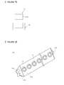
- FIG. 8 illustrates a perspective view of a light source unit 130 included in a lighting device according to another embodiment of the present invention.
- the light source unit 130 extends in the longitudinal direction of a reflector, and includes a body 132 having first and second inclined surfaces, light emitting recesses 133 provided to the first and second inclined surfaces, light emitting diodes 131 installed on the light emitting recesses 133, and first and second connection terminals 136 and 137 disposed at both ends of the body 132.
- the light emitting recesses 133 are disposed partially in both side surfaces of the body 132 only at positions where the light emitting diodes 131 are installed. That is, the light emitting recesses 133 are spaced apart from each other in the body 132.
- the upper portion of the light emitting recesses 133 can also have various shapes including circular, oval and polygonal shapes in a plan view.
- the light emitting diodes 131 are also arrayed in the light emitting recesses 133.
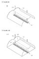
- FIG. 9 is a perspective view illustrating a lighting device 200 according to another embodiment of the present invention.
- the lighting device 200 includes a light source unit 230, a reflector 220 and support units 210.
- the support units 210 have bar shapes, support the reflector 220 and the light source unit 230, and supply power to the light source unit 230. Further, the support units 210 extend from an external support member such as a ceiling disposed above the reflector 220 and receive power from an external power source such as a power supply unit (PSU) installed at the external support member.
- PSU power supply unit
- a first end of the support unit 210 is connected to the external power source, and a second end passes through the reflector 220 and connects to an upper surface of the light source unit 230.
- the second end of the support unit 210 can also be adhered through adhesive or coupled through a screw member to the upper surface of the light source unit 230.
- a wire member can also be disposed in the support unit 210 so that electric current can flow through the wire member. Accordingly, power can be supplied to the light source unit 230 through the support unit 210.
- the upper surface of the light source unit 230 can include a connection terminal for connecting to the support unit 210.
- the light source unit 230 can then receive power from the support unit 210 through the connection terminal.
- the support unit 210 passes through the reflector 220 and supports and fixes the reflector 220.
- the support unit 210 passing through the reflector 220 can be firmly coupled to the reflector 220 through an adhesive, for example.
- a separate support member can be connected to the reflector 220 and support the reflector 220.
- Other connection or coupling mechanisms can also be used.
- FIG. 9 illustrates two support units 210, a single support unit or more than two support units can be provided.
- the shape of the support unit 210 can be varied.
- FIG. 10 is a perspective view illustrating a lighting device 200A according to another embodiment of the present invention.
- the lighting device 200A includes the light source unit 230, the reflector 220 and the support units 210 (the same as that shown in FIG. 9 ).
- the reflector 220 has a housing structure with an opening.
- inner surfaces 222 of the reflector 220 include socket parts 241 that supply power to the light source unit 230 and support the light source unit 230.
- the coupling relationship between the socket parts 241 and connection terminals of the light source unit 230, and the functions thereof are the same as those of the embodiment of FIG. 1 , a detailed description is omitted.
- the support units 210 having the bar shapes support the reflector 220 and the light source unit 230.
- the support units 210 also extend from an external support member such as a ceiling disposed above the reflector 220, receive power from an external power source such as a PSU installed at the external support member, and supply power to the socket parts 241 of the reflector 220.
- a first end of the support unit 210 is connected to the external power source, and a second end passes through the reflector 220 and connects to an upper surface of the light source unit 230.
- the second end of the support unit 210 can also be adhered through adhesive or coupled through a screw member to the upper surface of the light source unit 230.
- a wire member can also be disposed in the support unit 210 so that electric current can flow through the wire member. Accordingly, power can be supplied to the light source unit 230 through the support unit 210.
- the upper surface of the light source unit 230 can also include a connection terminal for connecting to the support unit 210.
- the light source unit 230 can then receive power from the support unit 210 through the connection terminal.
- the support unit 210 passes through the reflector 220 and supports and fixes the reflector 220.
- the support unit 210 passing through the reflector 220 can be firmly coupled to the reflector 220 through an adhesive, for example.
- a separate support member can be connected to the reflector 220 and support the reflector 220.
- Other connection or coupling mechanisms can also be used.
- FIG. 10 illustrates two support units 210, a single support unit or a plurality of support units can be provided.
- the shape of the support unit 210 can be varied.
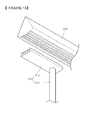
- FIG. 11 is a perspective view illustrating a lighting device 300 according to yet another embodiment of the present invention.
- the lighting device 300 includes a light source unit 330, a reflector 320 and support units 310.
- the support units 310 have bar shapes, are coupled to the reflector 320 and the light source unit 330, and support the reflector 320 and the light source unit 330.
- power is supplied to the light source unit 330 through the support units 310.
- the support units 310 extend from an external support member such as a bottom surface disposed under the light source unit 330, and receive power from an external power source such as PSU installed at the external support member.
- a first end of the support unit 310 is also connected to the external power source, and a second end is connected to a portion of a reflecting surface of the reflector 320.
- the second end of the support unit 310 can also be adhered through adhesive, or coupled through a screw member to the reflector 320.
- the support units 310 can also be connected to the reflector 320 passing through the light source unit 330. Further, the support unit 310 passing through the light source unit 330 can be firmly coupled to the light source unit 330.
- a wire member can also be disposed in the support unit 310 so that an electric current can flow through the wire member. Accordingly, power can be supplied to the light source unit 330 through the wire member.
- FIG. 11 illustrates two support units 210, a single support unit or a plurality of support units can be provided. Furthermore, the shape of the support unit 210 can be varied.
- FIG. 12 is a perspective view illustrating a lighting device 300A according to another embodiment of the present invention.
- the lighting device 300A includes the light source unit 330, the reflector 320 and support units 310 and 315.
- the support unit 310 will be referred to as a first support unit and the support unit 315 will be referred to as a second support unit.
- the first support unit 310 includes a coupling part 312 coupled to a lower surface of the light source unit 330, and a bar part 311 extending from an external support member under the light source unit 330 to supply power to the light source unit 330.
- the second support unit 315 also extends from an upper surface of the light source unit 330 to support the reflector 320.
- FIG. 13 is a schematic view illustrating the coupling relationship between the light source unit 330 and the first support unit 310 shown in FIG. 12 .
- the bar part 311 of the first support unit 310 has a bar shape
- the coupling part 312 has a shape corresponding to a convex-concave portion disposed at the lower surface of the light source unit 330 so that the coupling part 312 can be firmly coupled to the light source unit 330.
- the coupling part 312 of the first support unit 310 can also be used to transmit power to the light source unit 330.
- the bar part 311 of the first support unit 310 extends from an external support member such as a bottom surface disposed under the light source unit 330.
- the bar part 311 can also be used to receive power from an external power source such as a PSU installed at the external support member, and transmit the power to the light source unit 330.
- a wire member can also be disposed in the support unit 310 so that an electric current can flow through the wire member. Accordingly, power can be supplied to the light source unit 330 through the wire member.
- the second support unit 315 extends from the upper surface of the light source unit 330 to support and fix the reflector 320. Also, a single support unit or more than two support units can be used. The shape of the support unit can also be varied.
- FIG. 14 is a perspective view illustrating a lighting device 300B according to still another embodiment of the present invention.
- the lighting device 300B includes the light source unit 330, the reflector 320, the first support unit 310 and the second support unit 315 similar to the embodiment shown in FIG. 12 .
- the first support unit 310 includes the coupling part 312 coupled to the lower surface of the light source unit 330, and the bar part 311 extending from an external support member under the light source unit 330 to supply power to the light source unit 330.
- the second support unit 315 also extends from the upper surface of the light source unit 330 to support the reflector 320.
- the reflector 320 is a housing structure with an opening. Inner surfaces 322 of the reflector 320 also include the socket parts 341 that transmit power to the light source unit 330 and support the light source unit 330. Also, because the coupling relationship between the socket parts 341 and connection terminals of the light source unit 330, and the functions thereof are the same as those of the embodiment of FIG. 1 , a description of these parts is omitted. The other components have already been discussed with respect to FIG. 13 . Note also that the reflector 320 in FIG. 14 does not have a box shape on an upper surface as the reflector 20 in FIG. 2 .
- the present invention provides several advantages.
- the light source including the LEDs according to embodiments of the present invention have many advantages over fluorescent and incandescent light sources such as a lower power consumption, a long service life, a rapid response speed, a stable light source and environmentally-friendly properties.
- the lighting device of embodiments of the present invention can also be easily disassembled and repaired, if needed.
- the lighting device comprises recesses on the first and second outside surfaces, said recess extending along a longitudinal direction of the main body.
- each of the first and second surfaces comprises a plurality of recesses spaces apart from each other.
- any reference in this specification to "one embodiment,” “an embodiment,” “example embodiment,” etc. means that a particular feature, structure or characteristic described in connection with the embodiment is included in at least one embodiment of the invention.
- the appearances of such phrases in various places in the specification are not necessarily all referring to the same embodiment.
Abstract
a reflector (20) including at least one reflecting surface (21); and a light source unit (30) disposed in the vicinity of the reflector and comprising:
a main body (32) having a first outside surface (38) and a second outside surfaces (39), wherein each of said first and second outside surfaces is inclined with reference to the other; and
a plurality of first light emitting diodes (31) disposed on the first outside surface and a plurality of second light emitting diodes disposed on the second outside surface so that said first and second light emitting diodes are configured to emit light towards the reflector.
Description
- The present application claims priority to Korean Patent Application Nos.
10-2009-0058160 10-2009-0058161 10-2009-0058162 - The present disclosure relates to a lighting device including light emitting diodes (LEDs).
- Most lighting in homes, offices, parks, etc. is provided via fluorescent and incandescent lamps. However, these types of light sources are not environmentally friendly, tend to have limited or short life spans and have high power consumption. Thus, the costs of operating and maintaining these related art types of lighting sources are significant, especially when considering many light sources are turned on at a single instance.
- Accordingly, one object of the present invention is to address the above-noted and other problems.
- Another object of the present invention is to provide a novel lighting device including a plurality of light emitting diodes that provide a low power consumption, a long service life, a rapid response speed, a stable light source and environmentally-friendly properties.
- Yet another object of the present invention is to provide a novel lighting device that is easy to disassemble.
- To achieve these and other advantages and in accordance with the purpose of the present invention, as embodied and broadly described herein, the present invention provides in one aspect a lighting device including a reflector including a reflecting surface, and a light source unit disposed under the reflector and configured to emit light towards the reflector. Further, the light source unit includes a main body disposed longitudinally along the reflector and having first and second outside surfaces that are inclined towards the reflecting surface, and a plurality of first light emitting diodes disposed on the first outside surface and a plurality of second light emitting diodes disposed on the second outside surface and configured to emit the light towards the reflector.
- More precisely, the invention concerns a lighting device as recited in claim 1 and comprising a reflector including at least one reflecting surface, and a light source unit disposed in the vicinity of the reflector. The light source unit comprising a main body having a first outside surface and a second outside surfaces, wherein each of said first and second outside surfaces is inclined with reference to the other and a plurality of first light emitting diodes disposed on the first outside surface and a plurality of second light emitting diodes disposed on the second outside surface so that said first and second light emitting diodes are configured to emit light towards the reflector.
- Further scope of applicability of the present invention will become apparent from the detailed description given hereinafter. However, it should be understood that the detailed description and specific examples, while indicating preferred embodiments of the invention, are given by illustration only, since various changes and modifications within the invention will become apparent to those skilled in the art from this detailed description.
- The present invention will become more fully understood from the detailed description given hereinbelow and the accompanying drawings, which are given by illustration only, and thus are not limitative of the present invention, and wherein:
-
FIG. 1 is a cross-sectional view illustrating a lighting device according to an embodiment of the present invention; -
FIG. 2 is a perspective view illustrating the lighting device ofFIG. 1 ; -
FIG. 3 is a cross-sectional view illustrating a light source unit of the lighting device ofFIG. 1 ; -
FIG. 4 is a schematic view illustrating the light source unit ofFIG. 1 being removed from first and second socket parts; -
FIG. 5 is a schematic view illustrating the first and second socket parts ofFIG. 4 being coupled with the light source unit ofFIG. 1 ; -
FIG. 6 is a schematic view illustrating coupling mechanisms of a first connection terminal and the first socket part in the lighting device ofFIG. 1 ; -
FIG. 7 is a schematic view illustrating a coupling mechanism of a second connection terminal and the second socket part in the lighting device ofFIG. 1 ; -
FIG. 8 is a perspective view illustrating a light source unit of a lighting device according to another embodiment of the present invention; -
FIG. 9 is a perspective view illustrating a lighting device according to still another embodiment of the present invention; -
FIG. 10 is a perspective view illustrating a lighting device according to another embodiment of the present invention; -
FIG. 11 is a perspective view illustrating a lighting device according to yet another embodiment of the present invention; -
FIG. 12 is a perspective view illustrating a lighting device according to another embodiment of the present invention; -
FIG. 13 is a schematic view illustrating the coupling relationship between a light source unit of a lighting device and a first support unit according to an embodiment of the present invention; and -
FIG. 14 is a perspective view illustrating a lighting device according to another embodiment of the present invention. - Reference will now be made in detail to the preferred embodiments of the present invention, examples of which are illustrated in the accompanying drawings.
-
FIGS. 1 and 2 illustrate alighting device 100 according to an embodiment of the present invention. As shown, thelighting device 100 includes ahousing 10, areflector 20 and alight source unit 30. Further, in the embodiment shown inFIGS. 1 and 2 , thehousing 10 has a box shape to receive thereflector 20 and anopening 11 through which a reflectingsurface 21 of thereflector 20 is exposed and light is emitted. Thehousing 10 can also have shapes other than the box shape shown inFIGS. 1 and 2 . - In addition, the
reflector 20 is disposed within thehousing 10 and has a reflectingsurface 21 that reflects light emitted from thelight source unit 30. In the example shown inFIGS. 1 and 2 , the reflectingsurface 21 includes parabola-shapedreflecting surfaces surface 21 can have other shapes based on the structure of thelighting device 100. In addition, as shown inFIGS. 1 and 2 , the parabola-shaped reflectingsurfaces boundary 22 that is disposed in a longitudinal direction of thelighting device 100 and that vertically overlaps thelight source unit 30. Also, the material and color of thereflector 20 can be varied to achieve a specific illumination of thelighting device 100. For example, thereflector 20 can be formed of a white material having a high reflecting efficiency or be coated with silver (Ag) or aluminum (AI). - Further, according to an embodiment of the present invention, the
light source unit 30 can be held and placed within thehousing 10 via socket parts that interact and connect with terminals of thelight source unit 30.FIG. 2 illustrates a single socket part 42 (another socket part on the opposite side of thelight source 30 is not shown inFIG. 2 ). However,FIGS. 4-7 illustrate the socket parts and connection terminals in more detail. For Example,FIG. 4 illustratessockets parts connection terminals FIG. 5 illustrates the socket parts and connection terminals being connected together. As discussed above, thesocket parts housing 10 according to one embodiment of the present invention. - In more detail, and as shown in
FIG. 4 , both ends of thelight source unit 30 include the first andsecond connection terminals second socket parts housing 10. Thus, the first andsecond connection terminals second socket parts light source unit 30. In addition, the first andsecond connection terminals second socket parts light source 30. - Thus, in this embodiment, the first and
second socket parts second connection terminals light source unit 30. That is, the control part controlslight emitting diodes 31 of thelight source 30 to selectively emit light having a desired color, and adjusts the brightness and colors of thelight emitting diodes 31. As such, the control part controls thelight emitting diodes 31 installed on thelight source unit 30 to provide various illuminations. Also, when thelight source unit 30 reaches its service life or is broken, thelight source unit 30 can be easily replaced by removing the first andsecond connection terminals second socket parts - Next,
FIGS. 6 and7 illustrate the above-described coupling mechanisms. In more detail, and as shown inFIGS. 6 and7 , a shape of thefirst connection terminal 36 can be different from the shape of thesecond connection terminal 37, and the shape of thefirst socket part 41 can be different from the shape of thesecond socket part 42. Thus, thelight source unit 30 can be accurately coupled to the first andsecond socket parts FIG. 6 , thefirst connection terminal 36 includes ablock portion 36a and aprotrusion portion 36b protruding to the lower side of theblock portion 36a, and theblock portion 36a is integrally formed with theprotrusion portion 36b. In addition, thefirst socket part 41 has a shape corresponding to thefirst connection terminal 36, and theprotrusion portion 36b is inserted into an insertion portion disposed in thefirst socket part 41. - In addition, as shown in
FIG. 6(a) , a throughhole 41 a is disposed in the insertion portion, and theprotrusion portion 36b passes through the throughhole 41 a. Alternatively, and as shown inFIG. 6(b) , the insertion portion is provided with aninsertion recess 41 b, and theprotrusion portion 36b is disposed in theinsertion recess 41 b. Referring toFIG. 7 , thesecond connection terminal 37 can also include only ablock portion 37a, and thesecond socket part 42 can have a shape corresponding to thesecond connection terminal 37. Thus, thesecond connection terminal 37 can be inserted and coupled to thesecond socket part 42. However, the shapes of the first andsecond connection terminals second socket part - For example, the shape of the cross section of the
block portion second connection terminals protrusion portion 36b can have a circular, oval and polygonal shape. Moreover, the first andsecond connection terminals second connection terminals second connection terminals second socket parts second socket parts light source unit 30 and supply power to thelight source unit 30. - Next, a more detailed description of the
light source 30 will be given with respect toFIGS. 1-5 . In particular, as shown inFIGS. 1 and 2 , thelight source unit 30 is disposed in the middle of theopening 11 of thehousing 10 in a longitudinal direction with respect to thereflector 20. For example, thelight source unit 30 can be disposed in theopening 11 of thehousing 10 along theboundary 22 of thereflector 20. Further, as discussed above, thelight source unit 30 is supported and fixed by the first andsecond socket parts housing 10. - In addition, as shown in
FIG. 2 , thelight source unit 30 extends in the longitudinal direction of thereflector 20. Further, as shown in the different views ofFIGS. 1-5 , thelight source 30 includes abody 32 having one or more inclined surfaces, light emittingrecesses 33 provided to the inclined surfaces, light emitting diodes (LEDs) 31 installed on thelight emitting recesses 33, and the first andsecond connection terminals body 32. Further, the LEDs are semiconductor devices that convert electrical energy to light. - The
body 32 may be formed of a material adapted to efficiently emit heat such as aluminum (AI), stannum (Sn), nickel (Ni), silver (Ag), copper (Cu), titanium (Ti), molybdenum (Mo), tungsten (W), gold (Au), and platinum (Pt). Alternatively, thebody 32 may be formed of resin. In addition, thebody 32 may be formed of a white material having a high reflecting efficiency or be coated with silver (Ag) or aluminum (AI). Thus, the recesses formed in the body efficiently emit light from the LEDS toward the reflector. Thebody 32 may also have a polygonal cross section, and as shown inFIG. 2 , extend in the longitudinal direction of thereflector 20. Although thebody 32 has a fan-shaped cross section inFIGS. 1 to 5 , the shape of the cross section is not limited to this particular shape. - Also, as shown in
FIGS. 1 and3 , both side surfaces of thebody 32 include inclined surfaces such as first and secondinclined surfaces surface 21 of thereflector 20. That is, both the side surfaces of thebody 32 include the first and secondinclined surfaces surfaces surface 21, respectively (see alsoFIG. 2 ). The side surfaces of thebody 32 may be provided with one or more inclined surfaces and are not limited to the first and secondinclined surfaces - Further, as shown in
FIGS. 4 and5 , the first and secondinclined surfaces light emitting recesses 33 extending in the longitudinal direction of thereflector 20. The depths and widths of thelight emitting recesses 33 can be varied according to light distribution of thelight emitting diodes 31 installed on the light emitting recesses 33. The depths and widths of thelight emitting recesses 33 may also be adjusted to prevent light from being emitted directly to the outside through the opening 11 from thelight emitting diodes 31 so that light reflected by the reflectingsurface 21 is emitted to the outside through theopening 11. - In addition, as shown in
FIGS. 4 and5 , thelight emitting diodes 31 are installed in the light emitting recesses 33. In more detail, thelight emitting diodes 31 may be arrayed in thelight emitting recesses 33, and the number and arrangement of thelight emitting diodes 31 are not limited. Thelight emitting diodes 31 may also be selected among light emitting diodes which emit red, blue, green or white light. Other colors may also be used. Thus, according to an embodiment of the present invention, light emitted from thelight emitting diodes 31 is directed to the reflectingsurface 21 of thereflector 20, that is, to the parabola-shaped reflectingsurfaces light emitting diodes 31 is reflected to a user through thereflector 20 instead of being transmitted directly to the user. Accordingly, the glare from the light is reduced and soft light is provided to the user. - In addition, a substrate (not shown) is disposed in the
light emitting recesses 33, and thelight emitting diodes 31 are installed on the substrate to electrically connect thelight emitting diodes 31. Alternatively, a plurality of electrodes can be disposed in thelight emitting recesses 33 so that thelight emitting diodes 31 are electrically connected through the electrodes. Further, a lens can be disposed at thelight emitting recesses 33 to control the distribution of light emitted from thelight emitting diodes 31. Alternatively, thelight emitting recesses 33 can be filled with resin to control light distribution. A fluorescent member may also be added to the lens or the resin. Also, as shown in the embodiment inFIGS. 2-5 , a lower surface of thebody 32 includes a convex-concave portion 34 that increases the surface area of thelight source unit 30 to efficiently emit heat. The convex-concave portion 34 also extends in the longitudinal direction of thelight source unit 30 in this embodiment. - Next,
FIG. 8 illustrates a perspective view of alight source unit 130 included in a lighting device according to another embodiment of the present invention. As shown, thelight source unit 130 extends in the longitudinal direction of a reflector, and includes abody 132 having first and second inclined surfaces, light emittingrecesses 133 provided to the first and second inclined surfaces,light emitting diodes 131 installed on thelight emitting recesses 133, and first andsecond connection terminals body 132. - Further, the
light emitting recesses 133 are disposed partially in both side surfaces of thebody 132 only at positions where thelight emitting diodes 131 are installed. That is, thelight emitting recesses 133 are spaced apart from each other in thebody 132. The upper portion of thelight emitting recesses 133 can also have various shapes including circular, oval and polygonal shapes in a plan view. Thelight emitting diodes 131 are also arrayed in the light emitting recesses 133. - Next,
FIG. 9 is a perspective view illustrating alighting device 200 according to another embodiment of the present invention. As shown, thelighting device 200 includes alight source unit 230, areflector 220 andsupport units 210. Thesupport units 210 have bar shapes, support thereflector 220 and thelight source unit 230, and supply power to thelight source unit 230. Further, thesupport units 210 extend from an external support member such as a ceiling disposed above thereflector 220 and receive power from an external power source such as a power supply unit (PSU) installed at the external support member. - In addition, a first end of the
support unit 210 is connected to the external power source, and a second end passes through thereflector 220 and connects to an upper surface of thelight source unit 230. The second end of thesupport unit 210 can also be adhered through adhesive or coupled through a screw member to the upper surface of thelight source unit 230. A wire member can also be disposed in thesupport unit 210 so that electric current can flow through the wire member. Accordingly, power can be supplied to thelight source unit 230 through thesupport unit 210. - Also, the upper surface of the
light source unit 230 can include a connection terminal for connecting to thesupport unit 210. Thelight source unit 230 can then receive power from thesupport unit 210 through the connection terminal. Further, thesupport unit 210 passes through thereflector 220 and supports and fixes thereflector 220. In more detail, thesupport unit 210 passing through thereflector 220 can be firmly coupled to thereflector 220 through an adhesive, for example. Alternatively, a separate support member can be connected to thereflector 220 and support thereflector 220. Other connection or coupling mechanisms can also be used. Further, althoughFIG. 9 illustrates twosupport units 210, a single support unit or more than two support units can be provided. Furthermore, the shape of thesupport unit 210 can be varied. - Next,
FIG. 10 is a perspective view illustrating alighting device 200A according to another embodiment of the present invention. Referring toFIG. 10 , thelighting device 200A includes thelight source unit 230, thereflector 220 and the support units 210 (the same as that shown inFIG. 9 ). However, in this embodiment, thereflector 220 has a housing structure with an opening. Also, as shown inFIG. 10 ,inner surfaces 222 of thereflector 220 includesocket parts 241 that supply power to thelight source unit 230 and support thelight source unit 230. Also, because the coupling relationship between thesocket parts 241 and connection terminals of thelight source unit 230, and the functions thereof are the same as those of the embodiment ofFIG. 1 , a detailed description is omitted. - In addition, similar to the description above with respect to
FIG. 9 , thesupport units 210 having the bar shapes support thereflector 220 and thelight source unit 230. Thesupport units 210 also extend from an external support member such as a ceiling disposed above thereflector 220, receive power from an external power source such as a PSU installed at the external support member, and supply power to thesocket parts 241 of thereflector 220. In addition, a first end of thesupport unit 210 is connected to the external power source, and a second end passes through thereflector 220 and connects to an upper surface of thelight source unit 230. The second end of thesupport unit 210 can also be adhered through adhesive or coupled through a screw member to the upper surface of thelight source unit 230. A wire member can also be disposed in thesupport unit 210 so that electric current can flow through the wire member. Accordingly, power can be supplied to thelight source unit 230 through thesupport unit 210. - Also, the upper surface of the
light source unit 230 can also include a connection terminal for connecting to thesupport unit 210. Thelight source unit 230 can then receive power from thesupport unit 210 through the connection terminal. Further, thesupport unit 210 passes through thereflector 220 and supports and fixes thereflector 220. In more detail, thesupport unit 210 passing through thereflector 220 can be firmly coupled to thereflector 220 through an adhesive, for example. Alternatively, a separate support member can be connected to thereflector 220 and support thereflector 220. Other connection or coupling mechanisms can also be used. Further, althoughFIG. 10 illustrates twosupport units 210, a single support unit or a plurality of support units can be provided. Furthermore, the shape of thesupport unit 210 can be varied. - Next,
FIG. 11 is a perspective view illustrating alighting device 300 according to yet another embodiment of the present invention. As shown, thelighting device 300 includes alight source unit 330, areflector 320 andsupport units 310. Thesupport units 310 have bar shapes, are coupled to thereflector 320 and thelight source unit 330, and support thereflector 320 and thelight source unit 330. In addition, power is supplied to thelight source unit 330 through thesupport units 310. Thesupport units 310 extend from an external support member such as a bottom surface disposed under thelight source unit 330, and receive power from an external power source such as PSU installed at the external support member. - A first end of the
support unit 310 is also connected to the external power source, and a second end is connected to a portion of a reflecting surface of thereflector 320. The second end of thesupport unit 310 can also be adhered through adhesive, or coupled through a screw member to thereflector 320. Thesupport units 310 can also be connected to thereflector 320 passing through thelight source unit 330. Further, thesupport unit 310 passing through thelight source unit 330 can be firmly coupled to thelight source unit 330. A wire member can also be disposed in thesupport unit 310 so that an electric current can flow through the wire member. Accordingly, power can be supplied to thelight source unit 330 through the wire member. Further, althoughFIG. 11 illustrates twosupport units 210, a single support unit or a plurality of support units can be provided. Furthermore, the shape of thesupport unit 210 can be varied. -
FIG. 12 is a perspective view illustrating alighting device 300A according to another embodiment of the present invention. As shown, thelighting device 300A includes thelight source unit 330, thereflector 320 andsupport units support unit 310 will be referred to as a first support unit and thesupport unit 315 will be referred to as a second support unit. As shown inFIG. 12 , thefirst support unit 310 includes acoupling part 312 coupled to a lower surface of thelight source unit 330, and abar part 311 extending from an external support member under thelight source unit 330 to supply power to thelight source unit 330. Thesecond support unit 315 also extends from an upper surface of thelight source unit 330 to support thereflector 320. - Next,
FIG. 13 is a schematic view illustrating the coupling relationship between thelight source unit 330 and thefirst support unit 310 shown inFIG. 12 . Referring toFIGS. 12 and13 , thebar part 311 of thefirst support unit 310 has a bar shape, and thecoupling part 312 has a shape corresponding to a convex-concave portion disposed at the lower surface of thelight source unit 330 so that thecoupling part 312 can be firmly coupled to thelight source unit 330. Thecoupling part 312 of thefirst support unit 310 can also be used to transmit power to thelight source unit 330. - In addition, the
bar part 311 of thefirst support unit 310 extends from an external support member such as a bottom surface disposed under thelight source unit 330. Thebar part 311 can also be used to receive power from an external power source such as a PSU installed at the external support member, and transmit the power to thelight source unit 330. A wire member can also be disposed in thesupport unit 310 so that an electric current can flow through the wire member. Accordingly, power can be supplied to thelight source unit 330 through the wire member. Further, thesecond support unit 315 extends from the upper surface of thelight source unit 330 to support and fix thereflector 320. Also, a single support unit or more than two support units can be used. The shape of the support unit can also be varied. - Next,
FIG. 14 is a perspective view illustrating alighting device 300B according to still another embodiment of the present invention. As shown, thelighting device 300B includes thelight source unit 330, thereflector 320, thefirst support unit 310 and thesecond support unit 315 similar to the embodiment shown inFIG. 12 . In addition, thefirst support unit 310 includes thecoupling part 312 coupled to the lower surface of thelight source unit 330, and thebar part 311 extending from an external support member under thelight source unit 330 to supply power to thelight source unit 330. - The
second support unit 315 also extends from the upper surface of thelight source unit 330 to support thereflector 320. Further, thereflector 320 is a housing structure with an opening.Inner surfaces 322 of thereflector 320 also include thesocket parts 341 that transmit power to thelight source unit 330 and support thelight source unit 330. Also, because the coupling relationship between thesocket parts 341 and connection terminals of thelight source unit 330, and the functions thereof are the same as those of the embodiment ofFIG. 1 , a description of these parts is omitted. The other components have already been discussed with respect toFIG. 13 . Note also that thereflector 320 inFIG. 14 does not have a box shape on an upper surface as thereflector 20 inFIG. 2 . - Thus, the present invention provides several advantages. For example, the light source including the LEDs according to embodiments of the present invention have many advantages over fluorescent and incandescent light sources such as a lower power consumption, a long service life, a rapid response speed, a stable light source and environmentally-friendly properties. The lighting device of embodiments of the present invention can also be easily disassembled and repaired, if needed.
- In one embodiment, the lighting device comprises recesses on the first and second outside surfaces, said recess extending along a longitudinal direction of the main body.
- In another embodiment, each of the first and second surfaces comprises a plurality of recesses spaces apart from each other.
- In addition, any reference in this specification to "one embodiment," "an embodiment," "example embodiment," etc., means that a particular feature, structure or characteristic described in connection with the embodiment is included in at least one embodiment of the invention. The appearances of such phrases in various places in the specification are not necessarily all referring to the same embodiment. Further, when a particular feature, structure or characteristic is described in connection with any embodiment, it is submitted that it is within the purview of one skilled in the art to affect such feature, structure or characteristic in connection with other ones of the embodiments.
- As the present invention may be embodied in several forms without departing from the essential characteristics thereof, it should also be understood that the above-described embodiments are not limited by any of the details of the foregoing description, unless otherwise specified, but rather should be construed broadly within the appended claims, and therefore all changes and modifications that fall within the metes and bounds of the claims, or equivalence of such metes and bounds are therefore intended to be embraced by the appended claims.
Claims (15)
- A lighting device, comprising:a reflector (20; 220; 320) including at least one reflecting surface (21); anda light source unit (30; 230; 330) disposed in the vicinity of the reflector and comprising:a main body (32; 132) having a first outside surface (38) and a second outside surfaces (39), wherein each of said first and second outside surfaces is inclined with reference to the other; anda plurality of first light emitting diodes (31; 131) disposed on the first outside surface and a plurality of second light emitting diodes disposed on the second outside surface so that said first and second light emitting diodes are configured to emit light towards the reflector.
- The lighting device of claim 1, further comprising:first and second light emitting recesses (33; 133) respectively disposed within the first and second outside surfaces of the main body of the light source,wherein the plurality of first light emitting diodes are disposed within the first light emitting recess and the plurality of second light emitting diodes are disposed within the second light emitting recess.
- The lighting device of claim 2, further comprising:at least one of a lens disposed at the first and second light emitting recesses and a resin filled in the first and second light emitting recesses configured to control a distribution of light emitted from the light emitting diodes.
- The lighting device of any one of claims 1 to 3, wherein the main body comprises a substantially triangular shaped section and the first and second outside surfaces extend along adjacent sides of the triangular shape.
- The lighting device of any one of claims 1 to 4, wherein the main body includes a convex-concave shaped section portion (34; 134) on a lower surface of the main body connecting the first and second outside surfaces and facing downwards away from the first and second outside surfaces.
- The lighting device of any one of claims 1 to 5, wherein the reflector comprises two parabola shaped section reflectors (21 a, 21 b) joining together at a middle portion (22), and
wherein the main body of the light source unit is disposed at a position such that a symmetry axis of the section of the main body is aligned with said middle portion. - The lighting device of claim 6, wherein the reflector extends along a longitudinal axis with one parabola shaped section reflector on each side and further includes two inner housing surfaces (222; 322) perpendicular to the longitudinal axis and placed at extremities of the two parabola-shaped reflecting surfaces so as to form a reflecting housing.
- The lighting device of claim 7, further comprising:first and second connection terminals (36, 37; 136, 137) provided at first and second extremities of the light source unit; andfirst and second socket parts (341) disposed on the two inner surfaces of the reflector and configured to be respectively coupled to the first and second connection terminals to support and fix the light source unit and supply power to the light source unit.
- The lighting device of claim 8, further comprising:a control part disposed within at least one of the first and second connection terminals and first and second socket parts and configured to receive a driving signal to control and drive the light source unit.
- The lighting device of any one of claims 1 to 9, further comprising:a support unit configured to support the reflector and the light source unit.
- The lighting device of claim 10, further comprising a support unit (210) configured to support the reflector and the light source unit, wherein the support unit has a first end passing through the reflector and connecting to an upper surface of the main body of the light source unit, and has a second end configured to be connected to an external support member disposed above the reflector.
- The lighting device of claim 10, further comprising a support unit (311) configured to support the reflector and the light source unit, wherein the support unit has a first end passing through the main body of the light source and connecting to an inner surface of the reflector, and has a second end configured to be connected to an external support member disposed below the light source unit.
- The lighting device of claim 10, further comprising a support unit configured to support the reflector and the light source unit, wherein the support unit includes a first support unit (311) extending from a position below the main body of the light source unit and configured to engage with a lower surface of the main body of the light source unit, and a second support unit (315) configured to extend from a top surface of the main body of the light source unit to the reflector.
- The lighting device of claim 13, wherein the first support unit includes a coupling part (312) configured to couple the first support unit to the main body of the light source unit.
- The lighting device of claim 13, wherein the coupling part includes a convex-concave shaped section portion configured to engage with a convex-concave portion shaped section of the lower surface of the main body of the light source unit.
Applications Claiming Priority (3)
| Application Number | Priority Date | Filing Date | Title |
|---|---|---|---|
| KR1020090058160A KR20110000858A (en) | 2009-06-29 | 2009-06-29 | Lighting device |
| KR1020090058162A KR20110000860A (en) | 2009-06-29 | 2009-06-29 | Lighting device |
| KR1020090058161A KR20110000859A (en) | 2009-06-29 | 2009-06-29 | Lighting device |
Publications (3)
| Publication Number | Publication Date |
|---|---|
| EP2270390A2 true EP2270390A2 (en) | 2011-01-05 |
| EP2270390A3 EP2270390A3 (en) | 2011-03-09 |
| EP2270390B1 EP2270390B1 (en) | 2012-11-07 |
Family
ID=42729431
Family Applications (1)
| Application Number | Title | Priority Date | Filing Date |
|---|---|---|---|
| EP10166630A Not-in-force EP2270390B1 (en) | 2009-06-29 | 2010-06-21 | Lighting device |
Country Status (3)
| Country | Link |
|---|---|
| EP (1) | EP2270390B1 (en) |
| JP (2) | JP2011009223A (en) |
| CN (1) | CN101936469B (en) |
Cited By (3)
| Publication number | Priority date | Publication date | Assignee | Title |
|---|---|---|---|---|
| CN103453358A (en) * | 2013-07-15 | 2013-12-18 | 深圳市巧精灵照明有限公司 | Light-emitting-diode down lamp |
| US9200759B2 (en) | 2011-04-15 | 2015-12-01 | Cooper Crouse-Hinds Gmbh | Lamp having indirect light emission |
| ITUB20156252A1 (en) * | 2015-12-04 | 2017-06-04 | Clay Paky Spa | LIGHTING DEVICE |
Families Citing this family (16)
| Publication number | Priority date | Publication date | Assignee | Title |
|---|---|---|---|---|
| JP5442671B2 (en) * | 2011-06-10 | 2014-03-12 | 川重車両テクノ株式会社 | LED lighting fixtures |
| CN103649624A (en) * | 2011-07-15 | 2014-03-19 | Lg伊诺特有限公司 | Lighting device |
| KR101189082B1 (en) * | 2011-08-22 | 2012-10-10 | 엘지이노텍 주식회사 | Lighting device |
| CN102367919A (en) * | 2011-09-29 | 2012-03-07 | 苏州承源光电科技有限公司 | Light emitting diode (LED) fluorescent lamp |
| CN103187406A (en) * | 2011-12-27 | 2013-07-03 | 展晶科技(深圳)有限公司 | Package structure and package method of light emitting diode |
| US8702265B2 (en) * | 2012-04-05 | 2014-04-22 | Michael W. May | Non-curvilinear LED luminaries |
| US9228727B2 (en) | 2012-04-05 | 2016-01-05 | Michael W. May | Lighting assembly |
| CN103899942A (en) * | 2012-12-29 | 2014-07-02 | 欧普照明股份有限公司 | Illuminating lamp |
| CN105698015A (en) * | 2013-07-08 | 2016-06-22 | 李忠凯 | LED lamp |
| CN109114464B (en) * | 2014-04-18 | 2021-03-02 | 迈克尔·W·梅 | Light emitting assembly |
| CN104061505B (en) * | 2014-05-20 | 2016-09-07 | 厦门理工学院 | LED reflection formula pendent lamp |
| US10612736B2 (en) * | 2014-08-25 | 2020-04-07 | Molex, Llc | Luminaire |
| KR20180121495A (en) | 2016-01-07 | 2018-11-07 | 마이클 더블유. 메이 | Connector system for lighting assembly |
| US9739427B1 (en) | 2016-02-09 | 2017-08-22 | Michael W. May | Networked LED lighting system |
| NL2018788B1 (en) * | 2017-04-26 | 2018-11-05 | De Zeven Son B V | Lighting element as well as lighting provided with the lighting element |
| CN112254104B (en) * | 2020-10-19 | 2022-11-29 | 宁波腾钥电子科技有限公司 | Novel trailer lamp |
Family Cites Families (21)
| Publication number | Priority date | Publication date | Assignee | Title |
|---|---|---|---|---|
| US3683172A (en) * | 1970-08-14 | 1972-08-08 | Mobil Oil Corp | Suspended outdoor lighting fixture |
| JPS59159804U (en) * | 1983-04-12 | 1984-10-26 | 三菱電機株式会社 | stand type lighting equipment |
| JPH0451417Y2 (en) * | 1987-11-30 | 1992-12-03 | ||
| JPH07141905A (en) * | 1993-09-21 | 1995-06-02 | Kimmon Electric Co Ltd | Illuminating lamp |
| WO2003004930A1 (en) * | 2001-07-02 | 2003-01-16 | Moriyama Sangyo Kabushiki Kaisha | Display and illumination device and display and illumination system |
| JP2005056653A (en) * | 2003-08-01 | 2005-03-03 | Fuji Photo Film Co Ltd | Light source device |
| JP4044024B2 (en) * | 2003-09-29 | 2008-02-06 | 株式会社小糸製作所 | Vehicle headlamp |
| CN100492685C (en) * | 2003-12-05 | 2009-05-27 | 三菱电机株式会社 | Light emitting device and illumination instrument using the same |
| JP4804429B2 (en) * | 2003-12-05 | 2011-11-02 | 三菱電機株式会社 | Light emitting device and lighting apparatus using the same |
| DE10361118B4 (en) * | 2003-12-22 | 2011-12-22 | Auer Lighting Gmbh | Fresnels |
| WO2005078338A1 (en) * | 2004-02-17 | 2005-08-25 | Kelly William M | A utility lamp |
| CN2727544Y (en) * | 2004-08-18 | 2005-09-21 | 长春海拉车灯有限公司 | Lens car light with a spherical reflecting surface baffle |
| JP4492501B2 (en) * | 2005-09-09 | 2010-06-30 | パナソニック電工株式会社 | lighting equipment |
| WO2007054889A2 (en) * | 2005-11-11 | 2007-05-18 | Koninklijke Philips Electronics N.V. | A luminaire comprising leds |
| DE602007001479D1 (en) * | 2006-04-19 | 2009-08-20 | Faro Spa | Compact lighting device, especially applicable to a dental lamp |
| JP4892555B2 (en) * | 2006-06-30 | 2012-03-07 | シャープ株式会社 | Backlight module, method for manufacturing backlight module, lamp unit, lighting jig, lighting device, display device, and television receiver |
| JP2008243498A (en) * | 2007-03-27 | 2008-10-09 | First System Co Ltd | Led lighting device |
| US7824076B2 (en) * | 2007-05-31 | 2010-11-02 | Koester George H | LED reflector lamp |
| DE102007030186B4 (en) * | 2007-06-27 | 2009-04-23 | Harald Hofmann | Linear LED lamp and lighting system with the same |
| DE102007043903A1 (en) * | 2007-09-14 | 2009-03-26 | Osram Gesellschaft mit beschränkter Haftung | Luminous device |
| WO2009067844A1 (en) * | 2007-11-28 | 2009-06-04 | Chihua Shieh | A light emitting diode illuminator |
-
2010
- 2010-02-26 CN CN201010124319.7A patent/CN101936469B/en active Active
- 2010-06-21 EP EP10166630A patent/EP2270390B1/en not_active Not-in-force
- 2010-06-29 JP JP2010147381A patent/JP2011009223A/en active Pending
-
2014
- 2014-04-07 JP JP2014078875A patent/JP5732573B2/en active Active
Non-Patent Citations (1)
| Title |
|---|
| None |
Cited By (4)
| Publication number | Priority date | Publication date | Assignee | Title |
|---|---|---|---|---|
| US9200759B2 (en) | 2011-04-15 | 2015-12-01 | Cooper Crouse-Hinds Gmbh | Lamp having indirect light emission |
| CN103453358A (en) * | 2013-07-15 | 2013-12-18 | 深圳市巧精灵照明有限公司 | Light-emitting-diode down lamp |
| ITUB20156252A1 (en) * | 2015-12-04 | 2017-06-04 | Clay Paky Spa | LIGHTING DEVICE |
| EP3176496A1 (en) * | 2015-12-04 | 2017-06-07 | CLAY PAKY S.p.A. | Lighting device |
Also Published As
| Publication number | Publication date |
|---|---|
| CN101936469A (en) | 2011-01-05 |
| JP2011009223A (en) | 2011-01-13 |
| JP5732573B2 (en) | 2015-06-10 |
| JP2014130849A (en) | 2014-07-10 |
| EP2270390A3 (en) | 2011-03-09 |
| EP2270390B1 (en) | 2012-11-07 |
| CN101936469B (en) | 2014-10-22 |
Similar Documents
| Publication | Publication Date | Title |
|---|---|---|
| US8376578B2 (en) | Lighting device | |
| EP2270390B1 (en) | Lighting device | |
| JP5806767B2 (en) | Lighting device | |
| JP5623814B2 (en) | Lighting device | |
| US9644800B2 (en) | LED linear lamp with up and down illumination | |
| KR101349843B1 (en) | Lighting apparatus | |
| KR101001600B1 (en) | Lighting device | |
| KR101049162B1 (en) | Tube type led lamp assembly | |
| JP2012204187A (en) | Lamp and lighting fixture | |
| JP2012204146A (en) | Led lighting fixture | |
| JP2012256570A (en) | Led lighting fixture | |
| JP2015015110A (en) | Light emitting module and lighting system | |
| JP2015061067A (en) | Light-emitting module and lighting device | |
| KR20110000859A (en) | Lighting device | |
| KR101873551B1 (en) | Illumination system | |
| KR20110083900A (en) | Led fluorescent lamp having improved emission efficiency | |
| KR101797488B1 (en) | Lighting device | |
| KR20100096979A (en) | Led lamp with many particular mirror | |
| JP2012099456A (en) | Lighting device | |
| KR101137890B1 (en) | LED illumination Lamp | |
| KR20110000860A (en) | Lighting device | |
| KR200154049Y1 (en) | Fluorescent lamp device | |
| KR20110000858A (en) | Lighting device | |
| KR101741152B1 (en) | Detachable type LED lighting device | |
| KR20130012673A (en) | Lighting device and lamp body of the same |
Legal Events
| Date | Code | Title | Description |
|---|---|---|---|
| PUAI | Public reference made under article 153(3) epc to a published international application that has entered the european phase |
Free format text: ORIGINAL CODE: 0009012 |
|
| 17P | Request for examination filed |
Effective date: 20100621 |
|
| AK | Designated contracting states |
Kind code of ref document: A2 Designated state(s): AL AT BE BG CH CY CZ DE DK EE ES FI FR GB GR HR HU IE IS IT LI LT LU LV MC MK MT NL NO PL PT RO SE SI SK SM TR |
|
| AX | Request for extension of the european patent |
Extension state: BA ME RS |
|
| PUAL | Search report despatched |
Free format text: ORIGINAL CODE: 0009013 |
|
| AK | Designated contracting states |
Kind code of ref document: A3 Designated state(s): AL AT BE BG CH CY CZ DE DK EE ES FI FR GB GR HR HU IE IS IT LI LT LU LV MC MK MT NL NO PL PT RO SE SI SK SM TR |
|
| AX | Request for extension of the european patent |
Extension state: BA ME RS |
|
| 17Q | First examination report despatched |
Effective date: 20111202 |
|
| GRAP | Despatch of communication of intention to grant a patent |
Free format text: ORIGINAL CODE: EPIDOSNIGR1 |
|
| RIC1 | Information provided on ipc code assigned before grant |
Ipc: F21Y 103/00 20060101ALN20120413BHEP Ipc: F21Y 101/02 20060101ALN20120413BHEP Ipc: F21S 8/08 20060101ALN20120413BHEP Ipc: F21V 29/00 20060101ALN20120413BHEP Ipc: F21V 7/22 20060101ALN20120413BHEP Ipc: F21V 7/06 20060101ALN20120413BHEP Ipc: F21V 23/06 20060101ALI20120413BHEP Ipc: F21S 8/04 20060101ALN20120413BHEP Ipc: F21V 21/112 20060101ALI20120413BHEP Ipc: F21V 7/00 20060101AFI20120413BHEP Ipc: F21V 21/116 20060101ALI20120413BHEP |
|
| GRAS | Grant fee paid |
Free format text: ORIGINAL CODE: EPIDOSNIGR3 |
|
| GRAA | (expected) grant |
Free format text: ORIGINAL CODE: 0009210 |
|
| AK | Designated contracting states |
Kind code of ref document: B1 Designated state(s): AL AT BE BG CH CY CZ DE DK EE ES FI FR GB GR HR HU IE IS IT LI LT LU LV MC MK MT NL NO PL PT RO SE SI SK SM TR |
|
| REG | Reference to a national code |
Ref country code: GB Ref legal event code: FG4D |
|
| REG | Reference to a national code |
Ref country code: AT Ref legal event code: REF Ref document number: 583163 Country of ref document: AT Kind code of ref document: T Effective date: 20121115 Ref country code: CH Ref legal event code: EP |
|
| REG | Reference to a national code |
Ref country code: IE Ref legal event code: FG4D |
|
| REG | Reference to a national code |
Ref country code: DE Ref legal event code: R096 Ref document number: 602010003487 Country of ref document: DE Effective date: 20130103 |
|
| REG | Reference to a national code |
Ref country code: NL Ref legal event code: T3 |
|
| REG | Reference to a national code |
Ref country code: AT Ref legal event code: MK05 Ref document number: 583163 Country of ref document: AT Kind code of ref document: T Effective date: 20121107 |
|
| REG | Reference to a national code |
Ref country code: LT Ref legal event code: MG4D |
|
| PG25 | Lapsed in a contracting state [announced via postgrant information from national office to epo] |
Ref country code: IS Free format text: LAPSE BECAUSE OF FAILURE TO SUBMIT A TRANSLATION OF THE DESCRIPTION OR TO PAY THE FEE WITHIN THE PRESCRIBED TIME-LIMIT Effective date: 20130307 Ref country code: FI Free format text: LAPSE BECAUSE OF FAILURE TO SUBMIT A TRANSLATION OF THE DESCRIPTION OR TO PAY THE FEE WITHIN THE PRESCRIBED TIME-LIMIT Effective date: 20121107 Ref country code: SE Free format text: LAPSE BECAUSE OF FAILURE TO SUBMIT A TRANSLATION OF THE DESCRIPTION OR TO PAY THE FEE WITHIN THE PRESCRIBED TIME-LIMIT Effective date: 20121107 Ref country code: HR Free format text: LAPSE BECAUSE OF FAILURE TO SUBMIT A TRANSLATION OF THE DESCRIPTION OR TO PAY THE FEE WITHIN THE PRESCRIBED TIME-LIMIT Effective date: 20121107 Ref country code: LT Free format text: LAPSE BECAUSE OF FAILURE TO SUBMIT A TRANSLATION OF THE DESCRIPTION OR TO PAY THE FEE WITHIN THE PRESCRIBED TIME-LIMIT Effective date: 20121107 Ref country code: NO Free format text: LAPSE BECAUSE OF FAILURE TO SUBMIT A TRANSLATION OF THE DESCRIPTION OR TO PAY THE FEE WITHIN THE PRESCRIBED TIME-LIMIT Effective date: 20130207 |
|
| PG25 | Lapsed in a contracting state [announced via postgrant information from national office to epo] |
Ref country code: PT Free format text: LAPSE BECAUSE OF FAILURE TO SUBMIT A TRANSLATION OF THE DESCRIPTION OR TO PAY THE FEE WITHIN THE PRESCRIBED TIME-LIMIT Effective date: 20130307 Ref country code: BE Free format text: LAPSE BECAUSE OF FAILURE TO SUBMIT A TRANSLATION OF THE DESCRIPTION OR TO PAY THE FEE WITHIN THE PRESCRIBED TIME-LIMIT Effective date: 20121107 Ref country code: PL Free format text: LAPSE BECAUSE OF FAILURE TO SUBMIT A TRANSLATION OF THE DESCRIPTION OR TO PAY THE FEE WITHIN THE PRESCRIBED TIME-LIMIT Effective date: 20121107 Ref country code: GR Free format text: LAPSE BECAUSE OF FAILURE TO SUBMIT A TRANSLATION OF THE DESCRIPTION OR TO PAY THE FEE WITHIN THE PRESCRIBED TIME-LIMIT Effective date: 20130208 Ref country code: SI Free format text: LAPSE BECAUSE OF FAILURE TO SUBMIT A TRANSLATION OF THE DESCRIPTION OR TO PAY THE FEE WITHIN THE PRESCRIBED TIME-LIMIT Effective date: 20121107 Ref country code: LV Free format text: LAPSE BECAUSE OF FAILURE TO SUBMIT A TRANSLATION OF THE DESCRIPTION OR TO PAY THE FEE WITHIN THE PRESCRIBED TIME-LIMIT Effective date: 20121107 |
|
| PG25 | Lapsed in a contracting state [announced via postgrant information from national office to epo] |
Ref country code: AT Free format text: LAPSE BECAUSE OF FAILURE TO SUBMIT A TRANSLATION OF THE DESCRIPTION OR TO PAY THE FEE WITHIN THE PRESCRIBED TIME-LIMIT Effective date: 20121107 |
|
| PG25 | Lapsed in a contracting state [announced via postgrant information from national office to epo] |
Ref country code: CZ Free format text: LAPSE BECAUSE OF FAILURE TO SUBMIT A TRANSLATION OF THE DESCRIPTION OR TO PAY THE FEE WITHIN THE PRESCRIBED TIME-LIMIT Effective date: 20121107 Ref country code: SK Free format text: LAPSE BECAUSE OF FAILURE TO SUBMIT A TRANSLATION OF THE DESCRIPTION OR TO PAY THE FEE WITHIN THE PRESCRIBED TIME-LIMIT Effective date: 20121107 Ref country code: EE Free format text: LAPSE BECAUSE OF FAILURE TO SUBMIT A TRANSLATION OF THE DESCRIPTION OR TO PAY THE FEE WITHIN THE PRESCRIBED TIME-LIMIT Effective date: 20121107 Ref country code: BG Free format text: LAPSE BECAUSE OF FAILURE TO SUBMIT A TRANSLATION OF THE DESCRIPTION OR TO PAY THE FEE WITHIN THE PRESCRIBED TIME-LIMIT Effective date: 20130207 Ref country code: DK Free format text: LAPSE BECAUSE OF FAILURE TO SUBMIT A TRANSLATION OF THE DESCRIPTION OR TO PAY THE FEE WITHIN THE PRESCRIBED TIME-LIMIT Effective date: 20121107 |
|
| PG25 | Lapsed in a contracting state [announced via postgrant information from national office to epo] |
Ref country code: IT Free format text: LAPSE BECAUSE OF FAILURE TO SUBMIT A TRANSLATION OF THE DESCRIPTION OR TO PAY THE FEE WITHIN THE PRESCRIBED TIME-LIMIT Effective date: 20121107 Ref country code: RO Free format text: LAPSE BECAUSE OF FAILURE TO SUBMIT A TRANSLATION OF THE DESCRIPTION OR TO PAY THE FEE WITHIN THE PRESCRIBED TIME-LIMIT Effective date: 20121107 |
|
| PLBE | No opposition filed within time limit |
Free format text: ORIGINAL CODE: 0009261 |
|
| STAA | Information on the status of an ep patent application or granted ep patent |
Free format text: STATUS: NO OPPOSITION FILED WITHIN TIME LIMIT |
|
| 26N | No opposition filed |
Effective date: 20130808 |
|
| PG25 | Lapsed in a contracting state [announced via postgrant information from national office to epo] |
Ref country code: ES Free format text: LAPSE BECAUSE OF FAILURE TO SUBMIT A TRANSLATION OF THE DESCRIPTION OR TO PAY THE FEE WITHIN THE PRESCRIBED TIME-LIMIT Effective date: 20130218 |
|
| PG25 | Lapsed in a contracting state [announced via postgrant information from national office to epo] |
Ref country code: CY Free format text: LAPSE BECAUSE OF FAILURE TO SUBMIT A TRANSLATION OF THE DESCRIPTION OR TO PAY THE FEE WITHIN THE PRESCRIBED TIME-LIMIT Effective date: 20121107 |
|
| REG | Reference to a national code |
Ref country code: DE Ref legal event code: R097 Ref document number: 602010003487 Country of ref document: DE Effective date: 20130808 |
|
| PG25 | Lapsed in a contracting state [announced via postgrant information from national office to epo] |
Ref country code: MC Free format text: LAPSE BECAUSE OF FAILURE TO SUBMIT A TRANSLATION OF THE DESCRIPTION OR TO PAY THE FEE WITHIN THE PRESCRIBED TIME-LIMIT Effective date: 20121107 |
|
| REG | Reference to a national code |
Ref country code: IE Ref legal event code: MM4A |
|
| PG25 | Lapsed in a contracting state [announced via postgrant information from national office to epo] |
Ref country code: IE Free format text: LAPSE BECAUSE OF NON-PAYMENT OF DUE FEES Effective date: 20130621 |
|
| REG | Reference to a national code |
Ref country code: CH Ref legal event code: PL |
|
| PG25 | Lapsed in a contracting state [announced via postgrant information from national office to epo] |
Ref country code: MT Free format text: LAPSE BECAUSE OF FAILURE TO SUBMIT A TRANSLATION OF THE DESCRIPTION OR TO PAY THE FEE WITHIN THE PRESCRIBED TIME-LIMIT Effective date: 20121107 |
|
| PG25 | Lapsed in a contracting state [announced via postgrant information from national office to epo] |
Ref country code: LI Free format text: LAPSE BECAUSE OF NON-PAYMENT OF DUE FEES Effective date: 20140630 Ref country code: CH Free format text: LAPSE BECAUSE OF NON-PAYMENT OF DUE FEES Effective date: 20140630 |
|
| REG | Reference to a national code |
Ref country code: FR Ref legal event code: PLFP Year of fee payment: 6 |
|
| PG25 | Lapsed in a contracting state [announced via postgrant information from national office to epo] |
Ref country code: SM Free format text: LAPSE BECAUSE OF FAILURE TO SUBMIT A TRANSLATION OF THE DESCRIPTION OR TO PAY THE FEE WITHIN THE PRESCRIBED TIME-LIMIT Effective date: 20121107 |
|
| PG25 | Lapsed in a contracting state [announced via postgrant information from national office to epo] |
Ref country code: TR Free format text: LAPSE BECAUSE OF FAILURE TO SUBMIT A TRANSLATION OF THE DESCRIPTION OR TO PAY THE FEE WITHIN THE PRESCRIBED TIME-LIMIT Effective date: 20121107 |
|
| PG25 | Lapsed in a contracting state [announced via postgrant information from national office to epo] |
Ref country code: MK Free format text: LAPSE BECAUSE OF FAILURE TO SUBMIT A TRANSLATION OF THE DESCRIPTION OR TO PAY THE FEE WITHIN THE PRESCRIBED TIME-LIMIT Effective date: 20121107 Ref country code: LU Free format text: LAPSE BECAUSE OF NON-PAYMENT OF DUE FEES Effective date: 20130621 Ref country code: HU Free format text: LAPSE BECAUSE OF FAILURE TO SUBMIT A TRANSLATION OF THE DESCRIPTION OR TO PAY THE FEE WITHIN THE PRESCRIBED TIME-LIMIT; INVALID AB INITIO Effective date: 20100621 |
|
| REG | Reference to a national code |
Ref country code: FR Ref legal event code: PLFP Year of fee payment: 7 |
|
| PGFP | Annual fee paid to national office [announced via postgrant information from national office to epo] |
Ref country code: NL Payment date: 20160511 Year of fee payment: 7 |
|
| PGFP | Annual fee paid to national office [announced via postgrant information from national office to epo] |
Ref country code: GB Payment date: 20160511 Year of fee payment: 7 |
|
| PGFP | Annual fee paid to national office [announced via postgrant information from national office to epo] |
Ref country code: FR Payment date: 20160512 Year of fee payment: 7 |
|
| REG | Reference to a national code |
Ref country code: NL Ref legal event code: MM Effective date: 20170701 |
|
| GBPC | Gb: european patent ceased through non-payment of renewal fee |
Effective date: 20170621 |
|
| PG25 | Lapsed in a contracting state [announced via postgrant information from national office to epo] |
Ref country code: NL Free format text: LAPSE BECAUSE OF NON-PAYMENT OF DUE FEES Effective date: 20170701 |
|
| REG | Reference to a national code |
Ref country code: FR Ref legal event code: ST Effective date: 20180228 |
|
| PG25 | Lapsed in a contracting state [announced via postgrant information from national office to epo] |
Ref country code: GB Free format text: LAPSE BECAUSE OF NON-PAYMENT OF DUE FEES Effective date: 20170621 |
|
| PG25 | Lapsed in a contracting state [announced via postgrant information from national office to epo] |
Ref country code: FR Free format text: LAPSE BECAUSE OF NON-PAYMENT OF DUE FEES Effective date: 20170630 |
|
| PG25 | Lapsed in a contracting state [announced via postgrant information from national office to epo] |
Ref country code: AL Free format text: LAPSE BECAUSE OF FAILURE TO SUBMIT A TRANSLATION OF THE DESCRIPTION OR TO PAY THE FEE WITHIN THE PRESCRIBED TIME-LIMIT Effective date: 20121107 |
|
| RIC2 | Information provided on ipc code assigned after grant |
Ipc: F21V 7/06 20060101ALN20120413BHEP Ipc: F21Y 101/02 20000101ALN20120413BHEP Ipc: F21V 21/116 20060101ALI20120413BHEP Ipc: F21V 29/00 20150101ALN20120413BHEP Ipc: F21S 8/08 20060101ALN20120413BHEP Ipc: F21V 23/06 20060101ALI20120413BHEP Ipc: F21S 8/04 20060101ALN20120413BHEP Ipc: F21V 7/22 20180101ALN20120413BHEP Ipc: F21V 7/00 20060101AFI20120413BHEP Ipc: F21V 21/112 20060101ALI20120413BHEP Ipc: F21Y 103/00 20160101ALN20120413BHEP |
|
| REG | Reference to a national code |
Ref country code: DE Ref legal event code: R081 Ref document number: 602010003487 Country of ref document: DE Owner name: SUZHOU LEKIN SEMICONDUCTOR CO. LTD., TAICANG, CN Free format text: FORMER OWNER: LG INNOTEK CO., LTD., SEOUL/SOUL, KR |
|
| PGFP | Annual fee paid to national office [announced via postgrant information from national office to epo] |
Ref country code: DE Payment date: 20220505 Year of fee payment: 13 |
|
| REG | Reference to a national code |
Ref country code: DE Ref legal event code: R119 Ref document number: 602010003487 Country of ref document: DE |