EP2269887B1 - Method for determining short wave rail position geometry and rail deflection under load - Google Patents
Method for determining short wave rail position geometry and rail deflection under load Download PDFInfo
- Publication number
- EP2269887B1 EP2269887B1 EP10001974.4A EP10001974A EP2269887B1 EP 2269887 B1 EP2269887 B1 EP 2269887B1 EP 10001974 A EP10001974 A EP 10001974A EP 2269887 B1 EP2269887 B1 EP 2269887B1
- Authority
- EP
- European Patent Office
- Prior art keywords
- wave
- filter
- track position
- long
- short
- Prior art date
- Legal status (The legal status is an assumption and is not a legal conclusion. Google has not performed a legal analysis and makes no representation as to the accuracy of the status listed.)
- Active
Links
Images


Classifications
-
- B—PERFORMING OPERATIONS; TRANSPORTING
- B61—RAILWAYS
- B61K—AUXILIARY EQUIPMENT SPECIALLY ADAPTED FOR RAILWAYS, NOT OTHERWISE PROVIDED FOR
- B61K9/00—Railway vehicle profile gauges; Detecting or indicating overheating of components; Apparatus on locomotives or cars to indicate bad track sections; General design of track recording vehicles
- B61K9/08—Measuring installations for surveying permanent way
-
- B—PERFORMING OPERATIONS; TRANSPORTING
- B61—RAILWAYS
- B61L—GUIDING RAILWAY TRAFFIC; ENSURING THE SAFETY OF RAILWAY TRAFFIC
- B61L23/00—Control, warning or like safety means along the route or between vehicles or trains
- B61L23/04—Control, warning or like safety means along the route or between vehicles or trains for monitoring the mechanical state of the route
- B61L23/042—Track changes detection
- B61L23/047—Track or rail movements
Definitions
- the invention relates to a method for determining short-wave track geometry and the rail subsidence under load, wherein the short-wave geometric track position of a rail vehicle to detect and separate from the influence of the wheelset load.
- Such a method is from the DE 26 17 192 A1 known.
- the maintenance of the tracks is based on geometrical sizes. Special inspection vehicles are used to inspect the deviation of the track from its ideal position. Because of the measurement techniques used, the current in-service inspection vehicles can only detect long-wave fault shapes under load with the required accuracy.
- measuring systems which detect the short-wave track geometry indirectly via measured wheel-set bearing accelerations and evaluate them directly or convert the wheel-set bearing accelerations into a vertical track-position deviation.
- a device for measuring wavy deformations of the rail rolling surface of a railroad track, selecting a wavelength from a selected range of wavelengths, measuring by means of a trolley and sensors, processing the signals, determining the depth of the deformation and setting a specific ratio ( DE 30 08 440 C2 ).
- the DE 34 44 723 C2 describes a device for detecting the track geometry with a laser, which is arranged on a rail vehicle.
- Optical measuring systems in rail vehicles require a high level of maintenance of the measuring technology (contamination) and are therefore not suitable for automated use.
- Indirect assessment of short-wave track geometry based on measured accelerations depends on several boundary conditions, such as: Vehicle speed, error amplitude and error length, so that no clear conclusion on the short-wave track geometry is possible.
- the invention has for its object to detect the short-wave geometric track position of a rail vehicle and to separate the influence of the wheelset load.
- the proportion without the influence of the wheelset load is comparable to the manual inspection.
- the remaining proportion corresponds to the long-wave track deviations, which result from long-wave track position disturbances and the rail depression under the influence of the wheelset load.
- filters can be used which filter the locally equidistant true vertical track position signal in the local area.
- the independent, separate design of the two filters which provide the long-wave component and the short-wave component are not suitable, since these filters in addition to different amplitude responses also have different phase responses and thus lost in the separation of the signal components essential information.
- the filter cutoff frequencies in the local area as well as the filter steepness are determined from measured track position signals which contain long-wave and short-wave track position deviations. This is done for example by means of spectral analyzes in the local frequency range.
- an FIR high-pass filter (HP filter) with the determined cutoff frequency and filter slope with a linear phase response is designed in the first step.
- the filter design provides the filter coefficients b k, HP .
- the filter coefficients bk , TP of the corresponding low-pass filter can be determined directly.
- b k . TP b k . AP - b k . HP
- method 2 involves the high-pass-filtering of the locally equidistant true-to-life vertical track signal z [n].
- the long-wave component z LW [n] of z [n] is obtained by subtracting z KW [ n] from z [n].
- z LW n z n - z KW n
- the short-wave component z KW [n] In order for the distribution of the locally equidistant vertical track position signal z [n] to take place without loss of information, the short-wave component z KW [n] must not exhibit any phase distortion compared to the signal z [n]. This is achieved by applying the high pass filter twice to the signal z [n], with the second order reversing the signal order.
- the input is a stationary equidistant vertical track position signal z [n], which was calculated from measured wheel set bearing accelerations (procedure according to the application for industrial property rights) DE 10 2008 062 143.9 ).
- the equidistant local increment is 0.2 m.
- the axle bearing accelerations were measured under a load of approx. 7 t.
- FIG. 6 shows the amplitude and phase response of the Butterworth high pass filter.
- the locally equidistant dimensionally accurate vertical track position signal z [n] is filtered twice with the HP filter, with the second filters reversing the signal sequence and thus the phase distortion of the HP filter is completely compensated.
- This high-pass-filtered signal is the short-wave track geometry in the center section without load.
- the long-wave component z LW [n] of z [n] is determined by subtraction.
- the short-wave component z KW [n] is subtracted from the locally equidistant dimensionally accurate vertical track position signal z [n].
- the result is the long-wave component z LW [n]. This proportion corresponds to the rail depression under the influence of the wheelset load and corresponds to the size of the hollow layer and the long-wave track deviation under the switch frog.
- FIG. 8 the comparison of a manual measurement on a switch frog with the determined short-wave component of a measurement from a rule train is compared.
Landscapes
- Engineering & Computer Science (AREA)
- Mechanical Engineering (AREA)
- Length Measuring Devices With Unspecified Measuring Means (AREA)
- Train Traffic Observation, Control, And Security (AREA)
Abstract
Description
Die Erfindung betrifft ein Verfahren zur Ermittlung von kurzwelliger Gleislagegeometrie und der Schieneneinsenkungen unter Last, wobei die kurzwellige geometrische Gleislage von einem Schienenfahrzeug aus zu erfassen und vom Einfluss der Radsatzlast zu trennen ist.The invention relates to a method for determining short-wave track geometry and the rail subsidence under load, wherein the short-wave geometric track position of a rail vehicle to detect and separate from the influence of the wheelset load.
Solch ein Verfahren ist aus der
Die Instandhaltung der Gleise erfolgt anhand geometrischer Größen. Für die Inspektion der Abweichung des Gleises von seiner idealen Lage werden spezielle Inspektionsfahrzeuge verwendet. Wegen der verwendeten Messverfahren können die derzeitigen, sich im Einsatz befindenden, Inspektionsfahrzeuge nur langwellige Fehlerformen unter Last mit der erforderlichen Genauigkeit erfassen.The maintenance of the tracks is based on geometrical sizes. Special inspection vehicles are used to inspect the deviation of the track from its ideal position. Because of the measurement techniques used, the current in-service inspection vehicles can only detect long-wave fault shapes under load with the required accuracy.
Bei der Inspektion von Weichen, Schienenauszüge und Schienenschweißstöße sind jedoch kurzwellige geometrische Abweichungen maßgebend. Daher werden diese Gleiskomponenten manuell geprüft ohne Last. Meist kommen hier Lineale, Lehren, etc. zum Einsatz.When inspecting points, rail extensions and rail weld joints, however, short-wave geometric deviations are decisive. Therefore, these track components are checked manually without load. Usually rulers, gauges, etc. are used here.
Für die Erfassung kurzwelliger geometrischer Abweichungen aus dem Fahrzeug sind optische Messverfahren bekannt. Weiterhin sind auch Messsysteme bekannt, welche die kurzwellige Gleisgeometrie indirekt über gemessene Radsatzlager-Beschleunigungen erfassen und diese direkt bewerten oder die Radsatzlagerbeschleunigungen in eine vertikale Gleislageabweichung umrechnen.For the detection of short-wave geometric deviations from the vehicle optical measuring methods are known. Furthermore, measuring systems are also known which detect the short-wave track geometry indirectly via measured wheel-set bearing accelerations and evaluate them directly or convert the wheel-set bearing accelerations into a vertical track-position deviation.
Bekannt ist eine Vorrichtung zur Messung von wellenförmigen Deformierungen der Schienenrolloberfläche eines Schienenweges, wobei eine Wellenlänge aus einem ausgewählten Bereich von Wellenlängen ausgewählt wird, eine Messung mittels eines Rollwagens und Sensoren durchgeführt, die Signale verarbeitet, die Tiefe der Deformation bestimmt und ein bestimmtes Verhältnis gesetzt wird (
Aus der
Die
Die manuelle Prüfung ist mit einem erheblichen zeitlichen und personellen Aufwand verbunden. Zudem müssen bei der manuellen Inspektion Sicherheitsvorkehrungen zum Arbeitsschutz und Schutz des Bahnbetriebes getroffen werden wie z.B. Sicherungsposten oder Streckensperrungen.The manual check is associated with a considerable expenditure of time and personnel. In addition, in the case of manual inspection, safety precautions for occupational safety and protection of the railway operation must be taken such as, for example, Assurance items or line closures.
Optische Messsysteme in Schienenfahrzeugen erfordern einen hohen Wartungsaufwand an der Messtechnik (Verschmutzung) und sind daher nicht für einen automatisierten Einsatz geeignet.Optical measuring systems in rail vehicles require a high level of maintenance of the measuring technology (contamination) and are therefore not suitable for automated use.
Die indirekte Beurteilung der kurzwelligen Gleisgeometrie anhand gemessener Beschleunigungen hängt von mehreren Randbedingungen ab wie z.B. Fahrzeuggeschwindigkeit, Fehleramplitude und Fehlerlänge, so dass kein eindeutiger Rückschluss auf die kurzwellige Gleisgeometrie möglich ist.Indirect assessment of short-wave track geometry based on measured accelerations depends on several boundary conditions, such as: Vehicle speed, error amplitude and error length, so that no clear conclusion on the short-wave track geometry is possible.
Werden gemessene Beschleunigungen in eine formtreue Gleisgeometrie umgerechnet, dann ist darin wie bei allen Messsystemen auf Schienenfahrzeugen der Einfluss der Radsatzlast mit enthalten.If measured accelerations are converted into a dimensionally stable track geometry, then, as with all measuring systems on rail vehicles, this includes the influence of the axle load.
Um die Nachteile des Standes der Technik zu überwinden, liegt der Erfindung die Aufgabe zugrunde, die kurzwellige geometrische Gleislage von einem Schienenfahrzeug aus zu erfassen und vom Einfluss der Radsatzlast zu trennen. Der Anteil ohne den Einfluss der Radsatzlast ist mit der manuellen Inspektion vergleichbar. Der verbleibende Anteil entspricht den langwelligen Gleislageabweichungen, welche sich aus langwelligen Gleislagestörungen und der Schieneneinsenkung unter dem Einfluss der Radsatzlast ergeben.To overcome the disadvantages of the prior art, the invention has for its object to detect the short-wave geometric track position of a rail vehicle and to separate the influence of the wheelset load. The proportion without the influence of the wheelset load is comparable to the manual inspection. The remaining proportion corresponds to the long-wave track deviations, which result from long-wave track position disturbances and the rail depression under the influence of the wheelset load.
Diese Aufgabe wird durch ein Verfahren mit den Merkmalen des Anspruchs 1 gelöst.This object is achieved by a method having the features of
Hierzu werden zwei Auswerteverfahren beschrieben, welche auf ortsäquidistante, formtreue vertikale Gleislagesignale angewendet werden, um diese in kurzwellige und langwellige Anteile aufzuteilen.For this purpose, two evaluation methods are described, which are applied to locally equidistant, true to form vertical track position signals in order to divide these into short-wave and long-wave components.
Für die Aufteilung nach Verfahren 1 können Filter verwendet werden, welche das ortsäquidistante formtreue vertikale Gleislagesignal im Ortsbereich filtern. Der unabhängige, getrennte Entwurf der beiden Filter welche den langwelligen Anteil und den kurzwelligen Anteil liefern sind nicht geeignet, da diese Filter neben unterschiedlichen Amplitudengängen auch unterschiedliche Phasengänge aufweisen und somit bei der Trennung der Signalanteile wesentliche Informationen verloren gehen.For the division according to
Beim erfindungsgemäßen Verfahren 1 kommen daher zwei aufeinander abgestimmte Filter zum Einsatz, bei dem der Hochpass-Filter mit bekannten Filterentwurfstechniken entwickelt wird. Die Filtergrenzfrequenzen im Ortsbereich sowie die Filtersteilheit werden aus gemessenen Gleislagesignalen ermittelt, welche langwellige und kurzwellige Gleislageabweichungen enthalten. Dies erfolgt beispielsweise mittels Spektralanalysen im Orts-Frequenz-Bereich.In the
Beim erfindungsgemäßen Verfahren 1 wird im ersten Schritt ein FIR-Hochpass-Filter (HP-Filter) mit der ermittelten Grenzfrequenz und Filtersteilheit mit linearem Phasengang entworfen. Der Filterentwurf liefert die Filterkoeffizienten bk,HP.In the
Die Anwendung des FIR-Hochpass-Filters auf das ortsäquidistante formtreue vertikale Gleislagesignal z[n] ergibt den kurzwelligen Anteil zKW[n].The application of the FIR high-pass filter to the locally equidistant true vertical track position signal z [n] yields the short-wave component z KW [n].
FIR-Filter: 
Bei FIR-Filter mit linearem Phasengang können die Filterkoeffizienten bk,TP des entsprechenden Tiefpass-Filters direkt bestimmt werden. 
Wobei die Filterkoeffizienten bk,AP des Allpass-Filters folgender maßen definiert sind: 
Die Anwendung des Tiefpass-Filters auf das ortsäquidistante formtreue vertikale Gleislagesignal z[n] ergibt den langwelligen Anteil zLW[n]. 
Da in diesem Fall die Ordnung des Hochpass-Filters gleich der Ordnung des Tiefpass-Filters ist und zugleich beide Filter linearen Phasengang haben, ergibt sich für beide Filter die gleiche Gruppenlaufzeit. Das ortsäquidistante formtreue vertikale Gleislagesignal z[n] wurde ohne Informationsverlust in die beiden Anteile zKW und zLW erlegt. 
Für den Fall, dass im ersten Schritt ein FIR-Hochpass-Filter mit nicht linearer Phase oder ein IIR-Hochpass-Filter verwendet wurde, wird nach Verfahren 2 das ortsäquidistante formtreue vertikale Gleislagesignal z[n] hochpassgefiltert.In the event that a FIR high-pass nonlinear-phase filter or an IIR high-pass filter was used in the first step,
Die Anwendung des Hochpass-Filters auf das ortsäquidistante formtreue vertikale Gleislagesignal z[n] ergibt den kurzwelligen Anteil zKW[n].The application of the high-pass filter to the locally equidistant true vertical track position signal z [n] yields the short-wave component z KW [n].
Bei FIR-Filter: 
Bei IIR-Filter: 
Den langwelligen Anteil zLW[n] von z[n] erhält man durch Subtraktion von zKW[n] von z[n]. 
Damit die Aufteilung des ortsäquidistanten formtreuen vertikalen Gleislagesignals z[n] ohne Informationsverlust erfolgen kann, darf der kurzwellige Anteil zKW[n] gegenüber dem Signal z[n] keine Phasenverzerrung aufweisen. Dies wird erreicht, indem das Hochpass-Filter zweimal auf das Signal z[n] angewendet wird, wobei bei der zweiten Filterung die Signalreihenfolge umgekehrt wird.In order for the distribution of the locally equidistant vertical track position signal z [n] to take place without loss of information, the short-wave component z KW [n] must not exhibit any phase distortion compared to the signal z [n]. This is achieved by applying the high pass filter twice to the signal z [n], with the second order reversing the signal order.
Durch die Subtraktion wurde das ortsäquidistante formtreue vertikale Gleislagesignal z[n] ohne Informationsverlust in die beiden Anteile zKW und zLW erlegt. 
Anhand eines Ausführungsbeispieles soll nachfolgend die Anwendung des beschriebenen Verfahrens näher erläutert werden.Reference to an embodiment, the application of the described method will be explained in more detail below.
Dabei zeigen:
-
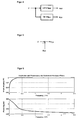
Figur 1 : einen Signalflussgrafen eines Hochpassfilters mit z als Eingangssignal und zKW als Ausgangssignal -
Figur 2 : die Amplitudengänge der HP-, und TP-Filter -
Figur 3 : den Amplitudengang eines Allpass-Filters -
Figur 4 : einen Signalflussgrafen für die Aufteilung der Gleislagegeometrie in kurzwellige und langwellige Anteile wobei FIR-Filter mit gleicher Filterordnung und linearen Phasengängen verwendet werden -
Figur 5 : einen Signalflussgraph der Subtraktion zKW von z -
Figur 6 : den Amplituden- und Phasengang des Butterworth-Hochpassfilters -
Figur 7 : die vertikalen Gleislageabweichungen z[n], zKW[n] und zLW[n] eines Weichenherzstückes im Ortsbereich -
Figur 8 : den Vergleich einer manuellen Messung an einem Weichenherzstück mit dem ermittelten kurzwelligen Anteil zKW[n] einer Messung aus einem Regelzug
-
FIG. 1 : a signal flow graph of a high-pass filter with z as the input signal and z KW as the output signal -
FIG. 2 : the amplitude responses of HP, and TP filters -
FIG. 3 : the amplitude response of an all-pass filter -
FIG. 4 : A Signalflussgrafen for splitting the track geometry in short-wave and long-wave proportions where FIR filters are used with the same filter order and linear phase responses -
FIG. 5 : a signal flow graph of the subtraction z KW of z -
FIG. 6 : the amplitude and phase response of the Butterworth high pass filter -
FIG. 7 : the vertical track deviations z [n], z KW [n] and z LW [n] of a switch frog in the local area -
FIG. 8 : the comparison of a manual measurement on a switch frog with the calculated short-wave component z KW [n] of a measurement from a control train
Als Eingabe dient ein ortsäquidistantes formtreues vertikales Gleislagesignal z[n] welches aus gemessenen Radsatzlager-Beschleunigungen berechnet wurde (Verfahren nach Schutzrechtsanmeldung
Im ersten Schritt wird ein Hochpass-Filter entworfen. Im Anwendungsbeispiel kommt ein Butterworth-Filter sechster Ordnung zum Einsatz. Die 3dB-Eckfrequenz beträgt 1/3m, so dass Wellenlängen größer 3 m aus dem Signal z[n] herausgefiltert werden. Hierbei handelt es sich um ein IIR-Filter mit nichtlinearer Phase (Verfahren 2). Die Filterkoeffizienten bk,HP und ak,HP wurden wie folgt bestimmt.
- b0,HP = 0.490231200703569
- b1,HP = -2.941387204221414
- b2,HP = 7.353468010553535
- b3,HP = -9.804624014071381
- b4,HP = 7.353468010553535
- b5,HP = -2.941387204221414
- b6,HP = 0.490231200703569
- a0,HP = 1.000000000000000
- a1,HP = -4.585886346766142
- a2,HP = 8.895035945278623
- a3,HP = -9.319068686462629
- a4,HP = 5.552670292723525
- a5,HP = -1.781808943261143
- a6,HP = 0.240326630536351
- b 0, HP = 0.490231200703569
- b 1, HP = -2.941387204221414
- b 2, HP = 7.353468010553535
- b 3, HP = -9.804624014071381
- b 4, HP = 7.353468010553535
- b 5, HP = -2.941387204221414
- b 6, HP = 0.490231200703569
- a 0, HP = 1.000000000000000
- a 1, HP = -4.585886346766142
- a 2, HP = 8.895035945278623
- a 3, HP = -9.319068686462629
- a 4, HP = 5.552670292723525
- a 5, HP = -1.781808943261143
- a 6, HP = 0.240326630536351
Das ortsäquidistante formtreue vertikale Gleislagesignal z[n] wird mit dem HP-Filter zweimal gefiltert, wobei bei zweiten Filtern die Signalreihenfolge umgekehrt wird und somit die Phasenverzerrung des HP-Filters vollständig kompensiert wird. Dieses hochpassgefilterte Signal ist die kurzwellige Gleisgeometrie im Herzstückbereich ohne Last.The locally equidistant dimensionally accurate vertical track position signal z [n] is filtered twice with the HP filter, with the second filters reversing the signal sequence and thus the phase distortion of the HP filter is completely compensated. This high-pass-filtered signal is the short-wave track geometry in the center section without load.
Da der, im ersten Schritt verwendete, Butterworth-Hochpass-Filter einen nichtlinearen Phasengang hat, wird der langwellige Anteil zLW[n] von z[n] durch Subtraktion ermittelt. Hierzu wird der kurzwellige Anteil zKW[n] vom ortsäquidistanten formtreuen vertikalen Gleislagesignal z[n] subtrahiert. Als Ergebnis erhält man den langwelligen Anteil zLW[n]. Dieser Anteil entspricht der Schieneneinsenkung unter dem Einfluss der Radsatzlast und entspricht der Größe der Hohllage und der langwelligen Gleislageabweichung unter dem Weichenherzstück.Since the Butterworth high-pass filter used in the first step has a non-linear phase response, the long-wave component z LW [n] of z [n] is determined by subtraction. For this purpose, the short-wave component z KW [n] is subtracted from the locally equidistant dimensionally accurate vertical track position signal z [n]. The result is the long-wave component z LW [n]. This proportion corresponds to the rail depression under the influence of the wheelset load and corresponds to the size of the hollow layer and the long-wave track deviation under the switch frog.
In
- im oberen Teil: das ortsäquidistante formtreue vertikale Gleislagesignal z[n]
- im mittleren Teil: der kurzwellige Anteil zKW[n] von z[n]
- im unteren Teil: der langwellige Anteil zLW[n] von z[n]
- in the upper part: the stationary equidistant vertical track position signal z [n]
- in the middle part: the short-wave component z KW [n] of z [n]
- in the lower part: the long-wave component z LW [n] of z [n]
In
Claims (6)
- A method for the distortion-free separation of true-to-form track position geometry into short-wave and long-wave fractions without information loss,
characterized in that
a locally equidistant, true-to-form, vertical track position signal is separated into a short-wave fraction corresponding to the geometry without a load and a long-wave fraction corresponding to the subsidence of the track under a load with long-wave track position deviations, wherein filters are used in the local range for the distortion-free separation and a filter is designed with known filter design techniques in the first step, wherein the characteristic filter limit frequency and the filter steepness are determined beforehand from the measured track position signals that contain long-wave and short-wave track position deviations, wherein this is preferably carried out by means of spectral analyses in the spatial frequency range and the separation of the locally equidistant, true-to-form, vertical track position signal takes place in dependence on the chosen filter type, as well as the phase response of the filter, wherein the second filter has, when using a FIR-filter with linear phase response, also a linear phase response and the same filter arrangement as the first filter and is calculated from the filter coefficients of the first filter, and wherein the locally equidistant, true-to-form, vertical track position signal is separated into a short-wave and a long-wave fraction due to the utilization of the two filters
or,
when using a FIR-filter with nonlinear phase response or an IIR-filter for the distortion-free separation of the locally equidistant, true-to-form, vertical track position signal into a short-wave and a long-wave fraction, the track position signal is filtered and a phase distortion is completely compensated by means of a second filtering with the same filter and the reverse signal sequence, wherein the characteristic filter limit frequency and the filter steepness are determined beforehand from the measured track position signals that contain long-wave and short-wave track position deviations, wherein this is preferably carried out by means of spectral analyses in the spatial frequency range and the long-wave or the short-wave fraction of the track position signal is respectively determined in dependence on the choice of filter, and wherein the associated second short-wave or long-wave fraction is respectively determined by subtracting the twice-filtered track position signal from the original track position. - The method according to Claim 1, characterized in that the short-wave fraction of the signal corresponds to the crossing geometry of switches, feathered joints or insulated joints and is evaluated.
- The method according to Claim 1, characterized in that the long-wave fraction of the signal corresponds to the rail subsidence under a load and the long-wave track position deviation and is evaluated.
- The method according to Claims 1 to 3, characterized in that the locally equidistant, true-to-form, vertical track position signals are determined by means of measurements carried out by track position inspection vehicles.
- The method according to Claims 1 to 4, characterized in that the locally equidistant, true-to-form, vertical track position signals are determined by means of measurements carried out by vehicles during normal operation.
- The method according to Claims 1 to 5, characterized in that the locally equidistant, true-to-form, vertical track position signals are determined by means of manual measurements.
Applications Claiming Priority (1)
| Application Number | Priority Date | Filing Date | Title |
|---|---|---|---|
| DE102009031819.4A DE102009031819B4 (en) | 2009-07-03 | 2009-07-03 | Method for determining short-wave track geometry and rail subsidence under load |
Publications (2)
| Publication Number | Publication Date |
|---|---|
| EP2269887A1 EP2269887A1 (en) | 2011-01-05 |
| EP2269887B1 true EP2269887B1 (en) | 2013-11-20 |
Family
ID=42664627
Family Applications (1)
| Application Number | Title | Priority Date | Filing Date |
|---|---|---|---|
| EP10001974.4A Active EP2269887B1 (en) | 2009-07-03 | 2010-02-26 | Method for determining short wave rail position geometry and rail deflection under load |
Country Status (2)
| Country | Link |
|---|---|
| EP (1) | EP2269887B1 (en) |
| DE (1) | DE102009031819B4 (en) |
Families Citing this family (1)
| Publication number | Priority date | Publication date | Assignee | Title |
|---|---|---|---|---|
| AT527178B1 (en) * | 2023-05-08 | 2025-06-15 | Plasser & Theurer Export Von Bahnbaumaschinen Gmbh | Procedure for checking the condition of a wheel check |
Family Cites Families (7)
| Publication number | Priority date | Publication date | Assignee | Title |
|---|---|---|---|---|
| CH592781A5 (en) * | 1975-04-23 | 1977-11-15 | Scheuchzer Auguste Les Fils De | |
| CH630015A5 (en) * | 1979-03-06 | 1982-05-28 | Speno International | DEVICE FOR MEASURING ONDULATORY DEFORMATIONS OF THE RUNNING SURFACE OF RAILS OF A RAILWAY. |
| CH653073A5 (en) * | 1982-10-18 | 1985-12-13 | Speno International | DEVICE FOR MEASURING THE DEPTH OF THE CORRECTION OF THE RUNNING SURFACE OF THE RAILS OF A RAILWAY. |
| DE3444723A1 (en) * | 1984-12-07 | 1986-06-12 | Richard Gehrcke | Device for detecting the track geometry by means of a laser |
| DE3913159A1 (en) * | 1989-04-21 | 1990-10-25 | Linsinger Maschinenbau Gmbh | Measuring wave-shaped rail deformation - using vehicle with two sensors measuring height difference of two rail top points |
| AU2003258632A1 (en) * | 2002-09-24 | 2004-04-19 | Db Netz Ag | Reconstruction of original signals from relative measurements |
| DE102008062143B3 (en) * | 2008-12-16 | 2010-05-12 | Db Netz Ag | Method for determining vertical track bed of rail-road traffic, involves interlinking vertical axle bearing path vectors, three-point longitudinal height vectors, and equally spaced stretching vectors, respectively |
-
2009
- 2009-07-03 DE DE102009031819.4A patent/DE102009031819B4/en not_active Expired - Fee Related
-
2010
- 2010-02-26 EP EP10001974.4A patent/EP2269887B1/en active Active
Also Published As
| Publication number | Publication date |
|---|---|
| DE102009031819A1 (en) | 2011-01-05 |
| DE102009031819B4 (en) | 2016-05-04 |
| EP2269887A1 (en) | 2011-01-05 |
Similar Documents
| Publication | Publication Date | Title |
|---|---|---|
| EP0040768B1 (en) | Monitoring device for an lc filter circuit of an alternating current network | |
| DE102007016395B3 (en) | Vehicle-specific quantification function determining method for track, involves determining regression coefficients for vehicle reaction by satisfying preset vehicle-specific quantification equation | |
| DE19852220C2 (en) | Process for the detection of damage in rail traffic | |
| EP1212228B1 (en) | Device for detecting eccentricities or wheel flats of rail vehicle wheels | |
| EP3329286A1 (en) | Method for detecting a defect in an acceleration sensor and measuring system | |
| EP3665036A1 (en) | Method for state determination of at least one overhead line extending along a route | |
| WO2013050244A1 (en) | Rail fracture detection method and device | |
| DE102008040195A1 (en) | Device and method for detecting rail-bound vehicle movements | |
| DE4312876B4 (en) | Device for measuring and determining the change on the tread of a wheel of rail vehicles | |
| EP2269887B1 (en) | Method for determining short wave rail position geometry and rail deflection under load | |
| DE10020519B4 (en) | Method for monitoring the driving properties of a rail vehicle | |
| DE3738696C2 (en) | Method and device for locating a broken rail | |
| DE4117924C1 (en) | Vertical and side force components measuring appts. for railway vehicle wheel - achieves simultaneous evaluation using circuits coupled to expansion measuring strips applied to opposite sides of crown of rail | |
| DE102017003162A1 (en) | Method and system for measuring forces Y and Q acting on a railroad track and for determining the ratio of these forces Y / Q | |
| EP0133199A1 (en) | Arrangement for the error control of a measuring device | |
| EP2378145A2 (en) | Method for monitoring a linear guide | |
| EP1197739B1 (en) | Method and apparatus for detecting a yaw damper failure on a railway vehicle | |
| DE3517114C2 (en) | ||
| DE102004032407B3 (en) | Acoustic method for an acoustic evaluation of rails in railway systems calculates a cumulative level velocity over measured rough spots on surfaces traversed | |
| AT527178B1 (en) | Procedure for checking the condition of a wheel check | |
| DE10114481A1 (en) | Dynamic measurement of axle load or weight of vehicle involves comparing dynamic force sensor signal profile in measurement window with vibration-independent reference signal profile | |
| DE69410287T2 (en) | RAILWAY MEASURING DEVICE FOR THE ANGULAR POSITION OF A TROLLEY WHEEL SET | |
| EP3837587B1 (en) | Assembly and method for detecting a measured value based on electron holography | |
| WO2023186400A1 (en) | Method and device for approximating an acceleration signal plot, detected when a railbound vehicle travels via a measurement route, to the characteristic features of a corresponding force signal plot | |
| DE102011082261B4 (en) | Method for providing a high quality signal value for the vertical acceleration of a wheel |
Legal Events
| Date | Code | Title | Description |
|---|---|---|---|
| PUAI | Public reference made under article 153(3) epc to a published international application that has entered the european phase |
Free format text: ORIGINAL CODE: 0009012 |
|
| 17P | Request for examination filed |
Effective date: 20101110 |
|
| AK | Designated contracting states |
Kind code of ref document: A1 Designated state(s): AT BE BG CH CY CZ DE DK EE ES FI FR GB GR HR HU IE IS IT LI LT LU LV MC MK MT NL NO PL PT RO SE SI SK SM TR |
|
| AX | Request for extension of the european patent |
Extension state: AL BA RS |
|
| GRAP | Despatch of communication of intention to grant a patent |
Free format text: ORIGINAL CODE: EPIDOSNIGR1 |
|
| INTG | Intention to grant announced |
Effective date: 20130826 |
|
| GRAS | Grant fee paid |
Free format text: ORIGINAL CODE: EPIDOSNIGR3 |
|
| GRAA | (expected) grant |
Free format text: ORIGINAL CODE: 0009210 |
|
| AK | Designated contracting states |
Kind code of ref document: B1 Designated state(s): AT BE BG CH CY CZ DE DK EE ES FI FR GB GR HR HU IE IS IT LI LT LU LV MC MK MT NL NO PL PT RO SE SI SK SM TR |
|
| REG | Reference to a national code |
Ref country code: GB Ref legal event code: FG4D Free format text: NOT ENGLISH |
|
| REG | Reference to a national code |
Ref country code: CH Ref legal event code: EP |
|
| REG | Reference to a national code |
Ref country code: AT Ref legal event code: REF Ref document number: 641405 Country of ref document: AT Kind code of ref document: T Effective date: 20131215 |
|
| REG | Reference to a national code |
Ref country code: IE Ref legal event code: FG4D Free format text: LANGUAGE OF EP DOCUMENT: GERMAN |
|
| REG | Reference to a national code |
Ref country code: DE Ref legal event code: R096 Ref document number: 502010005392 Country of ref document: DE Effective date: 20140116 |
|
| REG | Reference to a national code |
Ref country code: NL Ref legal event code: VDEP Effective date: 20131120 |
|
| REG | Reference to a national code |
Ref country code: LT Ref legal event code: MG4D |
|
| PG25 | Lapsed in a contracting state [announced via postgrant information from national office to epo] |
Ref country code: LT Free format text: LAPSE BECAUSE OF FAILURE TO SUBMIT A TRANSLATION OF THE DESCRIPTION OR TO PAY THE FEE WITHIN THE PRESCRIBED TIME-LIMIT Effective date: 20131120 Ref country code: IS Free format text: LAPSE BECAUSE OF FAILURE TO SUBMIT A TRANSLATION OF THE DESCRIPTION OR TO PAY THE FEE WITHIN THE PRESCRIBED TIME-LIMIT Effective date: 20140320 Ref country code: NO Free format text: LAPSE BECAUSE OF FAILURE TO SUBMIT A TRANSLATION OF THE DESCRIPTION OR TO PAY THE FEE WITHIN THE PRESCRIBED TIME-LIMIT Effective date: 20140220 Ref country code: FI Free format text: LAPSE BECAUSE OF FAILURE TO SUBMIT A TRANSLATION OF THE DESCRIPTION OR TO PAY THE FEE WITHIN THE PRESCRIBED TIME-LIMIT Effective date: 20131120 Ref country code: HR Free format text: LAPSE BECAUSE OF FAILURE TO SUBMIT A TRANSLATION OF THE DESCRIPTION OR TO PAY THE FEE WITHIN THE PRESCRIBED TIME-LIMIT Effective date: 20131120 Ref country code: NL Free format text: LAPSE BECAUSE OF FAILURE TO SUBMIT A TRANSLATION OF THE DESCRIPTION OR TO PAY THE FEE WITHIN THE PRESCRIBED TIME-LIMIT Effective date: 20131120 Ref country code: SE Free format text: LAPSE BECAUSE OF FAILURE TO SUBMIT A TRANSLATION OF THE DESCRIPTION OR TO PAY THE FEE WITHIN THE PRESCRIBED TIME-LIMIT Effective date: 20131120 |
|
| PG25 | Lapsed in a contracting state [announced via postgrant information from national office to epo] |
Ref country code: LV Free format text: LAPSE BECAUSE OF FAILURE TO SUBMIT A TRANSLATION OF THE DESCRIPTION OR TO PAY THE FEE WITHIN THE PRESCRIBED TIME-LIMIT Effective date: 20131120 Ref country code: ES Free format text: LAPSE BECAUSE OF FAILURE TO SUBMIT A TRANSLATION OF THE DESCRIPTION OR TO PAY THE FEE WITHIN THE PRESCRIBED TIME-LIMIT Effective date: 20131120 |
|
| PG25 | Lapsed in a contracting state [announced via postgrant information from national office to epo] |
Ref country code: PT Free format text: LAPSE BECAUSE OF FAILURE TO SUBMIT A TRANSLATION OF THE DESCRIPTION OR TO PAY THE FEE WITHIN THE PRESCRIBED TIME-LIMIT Effective date: 20140320 |
|
| PG25 | Lapsed in a contracting state [announced via postgrant information from national office to epo] |
Ref country code: EE Free format text: LAPSE BECAUSE OF FAILURE TO SUBMIT A TRANSLATION OF THE DESCRIPTION OR TO PAY THE FEE WITHIN THE PRESCRIBED TIME-LIMIT Effective date: 20131120 |
|
| REG | Reference to a national code |
Ref country code: DE Ref legal event code: R097 Ref document number: 502010005392 Country of ref document: DE |
|
| PG25 | Lapsed in a contracting state [announced via postgrant information from national office to epo] |
Ref country code: PL Free format text: LAPSE BECAUSE OF FAILURE TO SUBMIT A TRANSLATION OF THE DESCRIPTION OR TO PAY THE FEE WITHIN THE PRESCRIBED TIME-LIMIT Effective date: 20131120 Ref country code: CZ Free format text: LAPSE BECAUSE OF FAILURE TO SUBMIT A TRANSLATION OF THE DESCRIPTION OR TO PAY THE FEE WITHIN THE PRESCRIBED TIME-LIMIT Effective date: 20131120 Ref country code: RO Free format text: LAPSE BECAUSE OF FAILURE TO SUBMIT A TRANSLATION OF THE DESCRIPTION OR TO PAY THE FEE WITHIN THE PRESCRIBED TIME-LIMIT Effective date: 20131120 Ref country code: SK Free format text: LAPSE BECAUSE OF FAILURE TO SUBMIT A TRANSLATION OF THE DESCRIPTION OR TO PAY THE FEE WITHIN THE PRESCRIBED TIME-LIMIT Effective date: 20131120 |
|
| BERE | Be: lapsed |
Owner name: DEUTSCHE BAHN A.G. Effective date: 20140228 |
|
| PLBE | No opposition filed within time limit |
Free format text: ORIGINAL CODE: 0009261 |
|
| STAA | Information on the status of an ep patent application or granted ep patent |
Free format text: STATUS: NO OPPOSITION FILED WITHIN TIME LIMIT |
|
| PG25 | Lapsed in a contracting state [announced via postgrant information from national office to epo] |
Ref country code: DK Free format text: LAPSE BECAUSE OF FAILURE TO SUBMIT A TRANSLATION OF THE DESCRIPTION OR TO PAY THE FEE WITHIN THE PRESCRIBED TIME-LIMIT Effective date: 20131120 Ref country code: LU Free format text: LAPSE BECAUSE OF FAILURE TO SUBMIT A TRANSLATION OF THE DESCRIPTION OR TO PAY THE FEE WITHIN THE PRESCRIBED TIME-LIMIT Effective date: 20140226 Ref country code: MC Free format text: LAPSE BECAUSE OF FAILURE TO SUBMIT A TRANSLATION OF THE DESCRIPTION OR TO PAY THE FEE WITHIN THE PRESCRIBED TIME-LIMIT Effective date: 20131120 |
|
| REG | Reference to a national code |
Ref country code: CH Ref legal event code: PL |
|
| 26N | No opposition filed |
Effective date: 20140821 |
|
| GBPC | Gb: european patent ceased through non-payment of renewal fee |
Effective date: 20140226 |
|
| PG25 | Lapsed in a contracting state [announced via postgrant information from national office to epo] |
Ref country code: LI Free format text: LAPSE BECAUSE OF NON-PAYMENT OF DUE FEES Effective date: 20140228 Ref country code: CH Free format text: LAPSE BECAUSE OF NON-PAYMENT OF DUE FEES Effective date: 20140228 |
|
| REG | Reference to a national code |
Ref country code: FR Ref legal event code: ST Effective date: 20141031 |
|
| REG | Reference to a national code |
Ref country code: IE Ref legal event code: MM4A |
|
| REG | Reference to a national code |
Ref country code: DE Ref legal event code: R097 Ref document number: 502010005392 Country of ref document: DE Effective date: 20140821 |
|
| PG25 | Lapsed in a contracting state [announced via postgrant information from national office to epo] |
Ref country code: FR Free format text: LAPSE BECAUSE OF NON-PAYMENT OF DUE FEES Effective date: 20140228 Ref country code: GB Free format text: LAPSE BECAUSE OF NON-PAYMENT OF DUE FEES Effective date: 20140226 Ref country code: BE Free format text: LAPSE BECAUSE OF NON-PAYMENT OF DUE FEES Effective date: 20140228 Ref country code: IE Free format text: LAPSE BECAUSE OF NON-PAYMENT OF DUE FEES Effective date: 20140226 |
|
| PG25 | Lapsed in a contracting state [announced via postgrant information from national office to epo] |
Ref country code: SI Free format text: LAPSE BECAUSE OF FAILURE TO SUBMIT A TRANSLATION OF THE DESCRIPTION OR TO PAY THE FEE WITHIN THE PRESCRIBED TIME-LIMIT Effective date: 20131120 |
|
| PG25 | Lapsed in a contracting state [announced via postgrant information from national office to epo] |
Ref country code: IT Free format text: LAPSE BECAUSE OF FAILURE TO SUBMIT A TRANSLATION OF THE DESCRIPTION OR TO PAY THE FEE WITHIN THE PRESCRIBED TIME-LIMIT Effective date: 20131120 |
|
| PG25 | Lapsed in a contracting state [announced via postgrant information from national office to epo] |
Ref country code: MT Free format text: LAPSE BECAUSE OF FAILURE TO SUBMIT A TRANSLATION OF THE DESCRIPTION OR TO PAY THE FEE WITHIN THE PRESCRIBED TIME-LIMIT Effective date: 20131120 |
|
| REG | Reference to a national code |
Ref country code: AT Ref legal event code: MM01 Ref document number: 641405 Country of ref document: AT Kind code of ref document: T Effective date: 20150226 |
|
| PG25 | Lapsed in a contracting state [announced via postgrant information from national office to epo] |
Ref country code: SM Free format text: LAPSE BECAUSE OF FAILURE TO SUBMIT A TRANSLATION OF THE DESCRIPTION OR TO PAY THE FEE WITHIN THE PRESCRIBED TIME-LIMIT Effective date: 20131120 |
|
| PG25 | Lapsed in a contracting state [announced via postgrant information from national office to epo] |
Ref country code: AT Free format text: LAPSE BECAUSE OF NON-PAYMENT OF DUE FEES Effective date: 20150226 |
|
| PG25 | Lapsed in a contracting state [announced via postgrant information from national office to epo] |
Ref country code: BG Free format text: LAPSE BECAUSE OF FAILURE TO SUBMIT A TRANSLATION OF THE DESCRIPTION OR TO PAY THE FEE WITHIN THE PRESCRIBED TIME-LIMIT Effective date: 20131120 Ref country code: CY Free format text: LAPSE BECAUSE OF FAILURE TO SUBMIT A TRANSLATION OF THE DESCRIPTION OR TO PAY THE FEE WITHIN THE PRESCRIBED TIME-LIMIT Effective date: 20131120 Ref country code: GR Free format text: LAPSE BECAUSE OF FAILURE TO SUBMIT A TRANSLATION OF THE DESCRIPTION OR TO PAY THE FEE WITHIN THE PRESCRIBED TIME-LIMIT Effective date: 20140221 |
|
| PG25 | Lapsed in a contracting state [announced via postgrant information from national office to epo] |
Ref country code: HU Free format text: LAPSE BECAUSE OF FAILURE TO SUBMIT A TRANSLATION OF THE DESCRIPTION OR TO PAY THE FEE WITHIN THE PRESCRIBED TIME-LIMIT; INVALID AB INITIO Effective date: 20100226 Ref country code: TR Free format text: LAPSE BECAUSE OF FAILURE TO SUBMIT A TRANSLATION OF THE DESCRIPTION OR TO PAY THE FEE WITHIN THE PRESCRIBED TIME-LIMIT Effective date: 20131120 |
|
| PG25 | Lapsed in a contracting state [announced via postgrant information from national office to epo] |
Ref country code: MK Free format text: LAPSE BECAUSE OF FAILURE TO SUBMIT A TRANSLATION OF THE DESCRIPTION OR TO PAY THE FEE WITHIN THE PRESCRIBED TIME-LIMIT Effective date: 20131120 |
|
| PGFP | Annual fee paid to national office [announced via postgrant information from national office to epo] |
Ref country code: DE Payment date: 20260217 Year of fee payment: 17 |