EP1212228B1 - Device for detecting eccentricities or wheel flats of rail vehicle wheels - Google Patents
Device for detecting eccentricities or wheel flats of rail vehicle wheels Download PDFInfo
- Publication number
- EP1212228B1 EP1212228B1 EP00960575A EP00960575A EP1212228B1 EP 1212228 B1 EP1212228 B1 EP 1212228B1 EP 00960575 A EP00960575 A EP 00960575A EP 00960575 A EP00960575 A EP 00960575A EP 1212228 B1 EP1212228 B1 EP 1212228B1
- Authority
- EP
- European Patent Office
- Prior art keywords
- load cells
- accordance
- wagon
- rail
- wheel
- Prior art date
- Legal status (The legal status is an assumption and is not a legal conclusion. Google has not performed a legal analysis and makes no representation as to the accuracy of the status listed.)
- Expired - Lifetime
Links
Images

Classifications
-
- G—PHYSICS
- G01—MEASURING; TESTING
- G01M—TESTING STATIC OR DYNAMIC BALANCE OF MACHINES OR STRUCTURES; TESTING OF STRUCTURES OR APPARATUS, NOT OTHERWISE PROVIDED FOR
- G01M17/00—Testing of vehicles
- G01M17/08—Railway vehicles
- G01M17/10—Suspensions, axles or wheels
-
- B—PERFORMING OPERATIONS; TRANSPORTING
- B61—RAILWAYS
- B61K—AUXILIARY EQUIPMENT SPECIALLY ADAPTED FOR RAILWAYS, NOT OTHERWISE PROVIDED FOR
- B61K9/00—Railway vehicle profile gauges; Detecting or indicating overheating of components; Apparatus on locomotives or cars to indicate bad track sections; General design of track recording vehicles
- B61K9/12—Measuring or surveying wheel-rims
Definitions
- the invention relates to a device for detecting Out-of-roundness and flatness of wheels on rail vehicles according to the preamble of claim 1.
- Such a device for determining unround wheels railway vehicles is already known from DE 44 39 342 C2.
- this device are on a test section on Rail foot in the area of each threshold on both sides two each Sensors from strain gauges applied the threshold reaction forces to capture. Furthermore, there are thrust sensors provided, each at the beginning and end of the test section are arranged in the neutral phase of the rail.
- the runout is determined in detail there not described. Since in this arrangement, in particular the Threshold reaction forces are detected with force sensors, the consist of strain gauges directly on the Rail foot applied, these can be difficult against Damages are protected and are then only with high maintenance again.
- the invention is therefore the object of all Rohnrundrion in a wheel on the rail reliable and to determine exactly.
- the invention has the advantage that with this device except the flats also other roundnesses or RadMailbrüche are accurately and safely detectable.
- this device can also be integrated into the rail network without interruption is the ovality can be beneficial even at normal Traverse speed without affecting the operation respectively.
- Fig. 1 of the drawing shows a device for detection of non-circularities of vehicle wheels moved on the rail 7,
- the integrated in a weighing device and with a Evaluation device 12 is connected, which due to the vertical force introduction in under the rail 7 located load cells 3, 10 determines the runout.
- the device consists of two cross beams under the rails 7, which are designed as railway sleepers 2, 8. These Thresholds 2, 8 included under the rails 7 at each Side recesses 4, 9 in which the load cells 3, 10 are arranged are.
- the thresholds 2 provided with the load cells 3, 10 8 are fixed in a ballast bed 6. It can the sleepers may be glued to the ballast bed or on one fixed to the ground.
- the illustrated device consists of two equipped with load cells 3, 10 Thresholds 2, 8, wherein for less accurate detection at least a threshold 2 is necessary. Because of the out-of-roundness generated vertical forces strongly on the speed of passage is a device with a threshold 2 only at relatively high speeds overpass sufficient exactly evaluable.
- test section can be simultaneously weight load a bogie of a common railroad car determine with sufficient accuracy.
- the load cell is the third firmly connected to the threshold 3.
- the load cell 3 is transverse and arranged vertically below the rail 7. It is the Load cell 3 S-shaped and has above and below the deformation body 13 via force return elements 17, 18 formed by horizontal transverse slots 16, 19 are.
- the threshold 2, 8 are horizontally laterally and along the Rail cable channels 5 provided by the load cells 3, 10 and arranged at the beginning and end of the measuring section Schubworthsetzêt 1, 11 with an evaluation device 12th are electrically connected. All transducers 1, 3, 10, 11 brought to the evaluation device 12 via separate channels, so that for different evaluations the most suitable Associations of the signals can be made. But it can also all load cells 3, 10 connected in parallel to the evaluation device 12 be introduced, so that the temporal waveform and the assignment to the traversing axes, Loads or wagons through at least one additional rail switch is made at the beginning of the test section. The Function of the rail switch is doing at the same time the Schubschreibsaufêt 1, 11 met when driving over of the wheel generate a control pulse. At least for the evaluation Out-of-roundness and flatness detection is advantageous, at least for each rail 7 separate input channels provide to known disorders such as to be able to distinguish the sinus run from out-of-roundnesses.
- the signals of the load cells 3, 10 singly or as a sum saved and are through known center distances with the help of Schubworthsetzillon 1, 11 as a rail switch a particular car or its Assign axes or wheels.
- These signals are known via filter circuits of Noise components such as wagon vibrations or the Sinus run separated and summed up wagon-by-train. advantageously, is determined by the Schubschreibsetzillon 1, 11 Force bypass error considered, so that this sum the signal components the weight of the wagon or vehicle corresponds and as such, can be displayed.
- the waveform of an exactly round Rades on the rail 7 would correspond.
- the vertical force fluctuations in proportion to the average determined.
- regular deviations such as Wagon vibrations, sinusoidal and comparable Fault components are taken into account, adjusts the deviation Measure of out-of-roundness of the wheel judged. This runout can then be displayed or signaled as a non-circular defect as far as a predetermined limit is exceeded.
- the evaluation device 12 can also be designed in such a way that that from the detected and stored vertical force signals a reference signal waveform is determined.
- a reference signal waveform could by applying the rules of Nonlinear dynamics done by means of computing circuits.
- the evaluation device 12 determine an out-of-roundness or a flat spot and display.
- the evaluation device 12 in addition also the parallel rolling over the two rails 7 wheels signal-wise compare with each other and evaluate the locking accuracy to increase the roundness. So, for example, occur Shifting emphasis on one axis, so far a wheel has an out-of-roundness.
- Such criteria could additionally be used to assess the irregularities become.
- the at least one Rohmcardungsin or detect a bogie length can be provided so can even at low crossing speeds the out-of-roundness or flatness is recognized and simultaneously also be carried out a weighing.
- the evaluation device 12 could also simultaneously overload control and a focus check. It would have to the evaluation device 12 limit load ranges for certain Wagon types are given after identification compared with the measured weight and a detected Overload could be signaled or displayed.
- the Focus control could the evaluation device 12 via the measured axle loads and after identification of the wagon type with the help of the given center distances the center of gravity calculate and while moving the center of gravity of one predetermined range this also signals or displayed become.
Landscapes
- Engineering & Computer Science (AREA)
- Mechanical Engineering (AREA)
- Physics & Mathematics (AREA)
- General Physics & Mathematics (AREA)
- Force Measurement Appropriate To Specific Purposes (AREA)
- Length Measuring Devices With Unspecified Measuring Means (AREA)
- Machines For Laying And Maintaining Railways (AREA)
Abstract
Description
Die Erfindung betrifft eine Vorrichtung zur Feststellung von
Unrundheiten und Flachstellen an Rädern bei Schienenfahrzeugen
gemäß dem Oberbegriff des Patentanspruchs 1.The invention relates to a device for detecting
Out-of-roundness and flatness of wheels on rail vehicles
according to the preamble of
Im Zuge der Sicherheit des Bahnverkehrs bei immer höheren Zuggeschwindigkeiten ist es zunehmend wichtiger, auch schon geringe Unrundheiten und Flachstellen an Rädern von Eisenbahnfahrzeugen festzustellen. So besteht die Radaufstandskraft die auf die Schiene wirkt, sowohl aus einer statischen Gewichtsbelastung und einem dynamischen Anteil, der mit zunehmender Geschwindigkeit ansteigt. Dabei erhöht sich der dynamische Anteil der Radaufstandskraft, wenn das Rad unrund ist oder über Flachstellen verfügt. Insbesondere bei hohen Zuggeschwindigkeiten kann diese dynamische Radaufstandskraft bei Unrundheiten oder Flachstellen so groß werden, daß dadurch Schäden am Rad oder an der Schiene verursacht werden, die auch zu Zugunfällen führen können. Deshalb ist es wünschenswert, derartige Unrundheiten und Flachstellen sicher und frühzeitig ermitteln zu können.In the course of the safety of rail traffic at ever higher train speeds It is increasingly important, even small Out-of-roundness and flatness on wheels of railway vehicles determine. So is the Radaufstandskraft the acting on the rail, both from a static weight load and a dynamic share, which increases with increasing Speed increases. This increases the dynamic Proportion of wheel contact force when the wheel is out of round or has flats. Especially at high draw speeds This dynamic wheel rollover force can help with out-of-rounds or flats become so large that this causes damage be caused at the wheel or at the rail, which also leads to train accidents being able to lead. Therefore it is desirable to have such Determine non-circularities and flat spots safely and early to be able to.
Eine derartige Vorrichtung zur Ermittlung unrunder Räder an Eisenbahnfahrzeugen ist bereits durch die DE 44 39 342 C2 vorbekannt. Bei dieser Vorrichtung sind auf einer Meßstrecke am Schienenfuß im Bereich jeder Schwelle beidseitig jeweils zwei Sensoren aus Dehnungsmeßstreifen appliziert, die die Schwellenreaktionskräfte erfassen. Weiterhin sind noch Schubkraftsensoren vorgesehen, die jeweils am Anfang und Ende der Meßstrecke in der neutralen Phase der Schiene angeordnet sind. Such a device for determining unround wheels Railway vehicles is already known from DE 44 39 342 C2. In this device are on a test section on Rail foot in the area of each threshold on both sides two each Sensors from strain gauges applied the threshold reaction forces to capture. Furthermore, there are thrust sensors provided, each at the beginning and end of the test section are arranged in the neutral phase of the rail.
Wie aus den erfaßten Schubkräften und den Schwellenreaktionskräften die Unrundheit ermittelt wird, ist im einzelnen dort nicht beschrieben. Da bei dieser Anordnung insbesondere die Schwellenreaktionskräfte mit Kraftsensoren erfaßt werden, die aus Dehnungsmeßstreifen bestehen, die unmittelbar auf dem Schienenfuß appliziert sind, können diese nur schwer gegen Beschädigungen geschützt werden und sind dann auch nur mit hohem Aufwand wieder Instand zu setzen.As from the detected shear forces and the threshold reaction forces the runout is determined in detail there not described. Since in this arrangement, in particular the Threshold reaction forces are detected with force sensors, the consist of strain gauges directly on the Rail foot applied, these can be difficult against Damages are protected and are then only with high maintenance again.
Aus der DE-PS 1 170 445 ist ein Verfahren zu Ermittlung der Pfeilhöhe von Flachstellen an Einsenbahnrädern vorbekannt. Dort wird die Schienendurchbiegung, die durch die Flachstellen verursacht wird, als Stoßmeßwert ermittelt und mittels einer komplizierten Elektronikschaltung ausgewertet. Mit diesem Verfahren sind aber offensichtlich nur Flachstellen und keine anderen Unrundheiten feststellbar. Weiterhin ist aus dieser Schrift auch nicht bekannt, mit welchen Mitteln die Raddruckmeßwerte ermittelt werden.From DE-PS 1 170 445 a method for determining the Arrow height of flats on Einsenbahnrädern already known. There is the rail deflection, passing through the flats is determined, determined as a Stoßmeßwert and by means of a evaluated complicated electronic circuit. With this procedure but are obviously only flats and no other irregularities detectable. Furthermore, from this Scripture also not known by what means the Raddruckmeßwerte be determined.
Der Erfindung liegt deshalb die Aufgabe zugrunde, alle Radunrundheiten bei einem auf der Schiene fahrenden Rad zuverlässig und genau festzustellen.The invention is therefore the object of all Radunrundheiten in a wheel on the rail reliable and to determine exactly.
Diese Aufgabe wird durch die im Patentanspruch 1 angegebene
Erfindung gelöst. Weiterbildungen und vorteilhafte Ausgestaltungen
der Erfindung sind in den Unteransprüchen angegeben.This object is achieved by the specified in
Die Erfindung hat den Vorteil, daß mit dieser Vorrichtung außer den Flachstellen auch andere Unrundheiten oder Radreifenbrüche genau und sicher feststellbar sind. Da diese Vorrichtung auch ohne Unterbrechung in das Schienennetz integrierbar ist, kann die Unrundheit vorteilhafterweise auch bei normaler Überfahrgeschwindigkeit ohne Beeinträchtigung des Betriebsablaufs erfolgen. The invention has the advantage that with this device except the flats also other roundnesses or Radreifenbrüche are accurately and safely detectable. As this device can also be integrated into the rail network without interruption is the ovality can be beneficial even at normal Traverse speed without affecting the operation respectively.
Durch die Erfassung der Vertikalkräfte mit hochgenauen Wägezellen zwischen dem Schienenfuß und den Schwellen ist vorteilhafterweise auf einfache Art eine Kalibrierung und Reparatur der Vorrichtung durchführbar. Da diese Wägezellen gleichzeitig auch zur Wägung der überfahrenden Eisenbahnfahrzeuge genutzt werden können, ist vorteilhafterweise auch gleichzeitig während der Überfahrt eine Wägung, Überlastkontrolle und eine Schwerpunktermittlung durchführbar oder zumindest alternativ vornehmbar. So kann bei schneller Überfahrt mit der gleichen Vorrichtung die Unrundheit und Flachstellenprüfung erfolgen und bei langsamer Überfahrt die Wägung, Überlastkontrolle und Schwerpunktlage ermittelt werden.By recording the vertical forces with high-precision load cells between the rail foot and the thresholds is advantageously easy calibration and repair the device feasible. Because these load cells at the same time also used for weighing the overrunning railway vehicles can be advantageously also simultaneously during crossing a weighing, overload control and a Center of gravity determination feasible or at least alternatively vornehmbar. So when fast crossing with the same Device the ovality and flatness check done and at slow crossing the weighing, overload control and Center of gravity can be determined.
Bei einer besonderen Ausführungsart mit zusätzlichen Schubspannungsensoren können diese vorteilhafterweise gleichzeitig zur Kraftnebenschlußkorrektur und als Schienenschalter zur Achs- und Fahrzeugidentifizierung genutzt werden.In a particular embodiment with additional shear stress sensors These can be advantageously simultaneously for Kraftnebenschluss correction and as a rail switch for Axle and vehicle identification are used.
Durch den Einsatz von Wägezellen mit Kraftrückführungselementen (S-förmig, doppel-S-förmig) in einer weiteren besonderen Ausführungsart führen vorteilhafterweise auch Abweichungen vom vorgesehenen Krafteinleitungsort und -richtung nicht zu Meßfehlern, so daß aufwendige Mittel zur hochgenauen Krafteinleitung entbehrlich sind.Through the use of load cells with force feedback elements (S-shaped, double-S-shaped) in another special Implementation advantageously also lead to deviations from provided force application site and direction not to measurement errors, so that expensive means for high-precision force application are dispensable.
Die Erfindung wird anhand eines Ausführungsbeispiels, das in der Zeichnung dargestellt ist, näher erläutert. Es zeigen:
- Fig. 1:
- eine Vorrichtung zur Erkennung von Radunrundheiten und zur Feststellung des Fahrzeuggewichts, und
- Fig. 2:
- die Anordnung der Meßwertaufnehmer im Bereich einer Schiene.
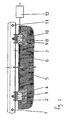
- Fig. 1:
- a device for detecting Radunrundheiten and for determining the vehicle weight, and
- Fig. 2:
- the arrangement of the transducers in the region of a rail.
Die Fig. 1 der Zeichnung zeigt eine Vorrichtung zur Ermittlung
von Unrundheiten von auf der Schiene 7 bewegten Fahrzeugrädern,
die in einer Wägeeinrichtung integriert und mit einer
Auswerteeinrichtung 12 verbunden ist, die aufgrund der Vertikalkrafteinleitung
in unter der Schiene 7 befindlichen Wägezellen
3, 10 die Unrundheit feststellt.Fig. 1 of the drawing shows a device for detection
of non-circularities of vehicle wheels moved on the
Die Vorrichtung besteht aus zwei Querträgern unter den Schienen
7, die als Eisenbahnschwellen 2, 8 ausgebildet sind. Diese
Schwellen 2, 8 enthalten unter den Schienen 7 jeweils an jeder
Seite Aussparungen 4, 9 in denen die Wägezellen 3, 10 angeordnet
sind. Die mit den Wägezellen 3, 10 versehenen Schwellen 2,
8 sind ortsfest in einem Schotterbett 6 verlegt. Dabei können
die Schwellen mit dem Schotterbett verklebt sein oder auf einem
festen Untergrund befestigt werden. Die dargestellte Vorrichtung
besteht aus zwei mit Wägezellen 3, 10 ausgestatteten
Schwellen 2, 8, wobei für eine weniger genaue Erkennung mindestens
eine Schwelle 2 notwendig ist. Da die durch die Unrundheit
erzeugten Vertikalkräfte stark von der Überfahrgeschwindigkeit
abhängen, ist eine Vorrichtung mit einer Schwelle 2
nur bei relativ hohen Überfahrgeschwindigkeiten hinreichend
genau auswertbar. Für eine genauere Messung der Unrundheit und
der Flachstellen hat sich eine Meßstrecke von 5,6 Metern mit
acht Meßstellen als ausreichend genau herausgestellt, die auch
für niedrige Überfahrgeschwindigkeiten geeignet ist. Mit einer
derartigen Meßstrecke läßt sich gleichzeitig auch die Gewichtsbelastung
eines Drehgestells eines gebräuchlichen Eisenbahnwaggons
hinreichend genau ermitteln.The device consists of two cross beams under the
Dazu sind in den Aussparungen 4, 9 der Schwellen 2, 8 Meßwertaufnehmer
angeordnet, die als Wägezellen 3, 10 ausgebildet
sind und auf denen sich die Schienen 7 abstützen. Die spezielle
Anordnung und Ausführung der Wägezellen 3, 10 in den Aussparungen
4, 9 der Schwelle 2 ist im einzelnen aus Fig. 2 der
Zeichnung ersichtlich. In der Aussparung 4 ist die Wägezelle 3
fest mit der Schwelle 3 verbunden. Die Wägezelle 3 ist quer
und senkrecht unter der Schiene 7 angeordnet. Dabei ist die
Wägezelle 3 S-förmig ausgebildet und verfügt oberhalb und unterhalb
des Verformungskörpers 13 über Kraftrückführungselemente
17, 18, die durch horizontale Querschlitze 16, 19 gebildet
sind. Etwa in der Mitte des Verformungskörpers 13 sind
in zwei gegeneinander gerichtete Sackbohrungen 14 Dehnungsmeßstreifen
15 appliziert, die bei einer Belastung ein Signal
erzeugen, das der eingeleiteten Vertikalkraft proportional
ist. Auf dem oberen Kraftrückführungselement 18 ist eine der
Schienen 7 befestigt, über die bei einer Überfahrt mit einem
Fahrzeugrad die Kraft in die Wägezelle 3 eingeleitet wird. Zur
Verbesserung der Genauigkeitsanforderungen kann auch eine sogenannte
Doppel-S-Wägezelle unter jeder Schiene eingesetzt
werden, die im Grunde wie zwei seitlich zusammengefügte S-förmige
Wägezellen aufgebaut ist.For this purpose, in the
Unterhalb der Schiene 7 und den kraftaufnehmenden Querträgern
oder Schwellen 2, 8 können auch andere Kraftaufnehmer oder
Wägezellen vorgesehen werden, soweit durch diese die durch die
Räder eingeleiteten Vertikalkräfte ermittelbar sind.Below the
In der Schwelle 2, 8 sind horizontal seitlich und längs der
Schiene Kabelkanäle 5 vorgesehen, durch die die Wägezellen 3,
10 und die am Anfang und Ende der Meßstrecke angeordneten
Schubspannungsaufnehmer 1 ,11 mit einer Auswertevorrichtung 12
elektrisch verbunden sind. Dabei sind alle Aufnehmer 1, 3, 10,
11 über separate Kanäle an die Auswertevorrichtung 12 herangeführt,
so daß für unterschiedliche Auswertungen die geeignetsten
Verknüpfungen der Signale erfolgen können. Es können aber
auch alle Wägezellen 3, 10 parallel geschaltet an die Auswertevorrichtung
12 herangeführt sein, so daß der zeitliche Signalverlauf
und die Zuordnung zu den überfahrenden Achsen,
Lasten oder Waggons durch mindestens einen zusätzlichen Schienenschalter
am Anfang der Meßstrecke vorgenommen wird. Die
Funktion des Schienenschalters wird dabei gleichzeitig durch
die Schubspannungsaufnehmer 1, 11 erfüllt, die beim Überfahren
des Rades einen Steuerimpuls erzeugen. Zumindest für die Auswertung
der Unrundheit und der Flachstellenfeststellung ist es
vorteilhaft, mindestens für jede Schiene 7 separate Eingangskanäle
vorzusehen, um bekannte Störungen wie beispielsweise
den Sinuslauf gegenüber Unrundheiten unterscheiden zu können.In the
In der Auswertevorrichtung 12 werden beim Überfahren der
Schienen 7 durch ein Schienenfahrzeug die Signale der Wägezellen
3, 10 einzeln oder als Summe gespeichert und sind durch
bekannte Achsabstände mit Hilfe der Schubspannungsaufnehmer 1,
11 als Schienenschalter einem bestimmten Waggon oder dessen
Achsen bzw. Rädern zuzuordnen. In der Auswertevorrichtung 12
werden diese Signale über Filterschaltungen von bekannten
Störanteilen wie beispielsweise Waggonschwingungen oder den
Sinuslauf getrennt und Waggonweise aufsummiert. Vorteilhafterweise
wird der durch die Schubspannungsaufnehmer 1, 11 ermittelte
Kraftnebenschlußfehler berücksichtigt, so daß diese Summe
der Signalanteile dem Gewicht des Waggons bzw. Fahrzeugs
entspricht und als solches,anzeigbar ist.In the
Durch die Aufsummierung der erfaßten Radaufstandskraftsignale
beim Überfahren der Meßstrecke bildet die Auswertevorrichtung
12 einen Mittelwert, der dem Signalverlauf eines exakt runden
Rades auf der Schiene 7 entsprechen würde. Da hingegen ein
unrundes Rad oder ein Flachstellenrad beim Überfahren einer
Meßstrecke periodische Vertikalkraftschwankungen verursacht,
werden in der Auswertevorrichtung 12 die Vertikalkraftschwankungen
mit dem ermittelten Mittelwert ins Verhältnis gesetzt.
Soweit im Mittelwert bereits regelmäßige Abweichungen wie beispielsweise
Waggonschwingungen, Sinuslauf und vergleichbare
Störanteile berücksichtigt wurden, stellt die Abweichung ein
Maß der Unrundheit des beurteilten Rades dar. Diese Unrundheit
kann dann angezeigt oder als Unrunddefekt signalisiert werden,
soweit ein vorgegebener Grenzwert überschritten wird.By the summation of the detected Radaufstandskraftsignale
when crossing the test section forms the
Die Auswertevorrichtung 12 kann aber auch so ausgebildet sein,
daß aus den erfaßten und gespeicherten Vertikalkraftsignalen
ein Referenzsignalverlauf ermittelt wird. Ein derartiger Referenzsignalverlauf
könnte durch die Anwendung der Regeln der
nichtlinearen Dynamik mit Hilfe von Rechenschaltungen erfolgen.
Durch Vergleich des Referenzsignalsverlaufs mit dem tatsächlichen
Signalverlauf eines Rades kann die Auswertevorrichtung
12 dann eine Unrundheit oder eine Flachstelle ermitteln
und anzeigen. Dabei kann die Auswertevorrichtung 12 zusätzlich
auch die parallel über die beiden Schienen 7 rollenden Räder
signalmäßig miteinander vergleichen und bewerten, um die Feststellgenauigkeit
der Unrundheiten zu erhöhen. So treten beispielweise
Schwerpunktverlagerungen auf einer Achse auf, soweit
ein Rad eine Unrundheit aufweist. Derartige Kriterien
könnten zur Beurteilung der Unrundheiten zusätzlich herangezogen
werden.However, the
Je nach den Genauigkeitsanforderungen ist die Länge der Meßstrecke
oder die Überfahrgeschwindigkeit festzulegen. Bei hohen
Überfahrgeschwindigkeiten kann die Unrundheit der Räder
bereits von Meßstrecken mit nur einem Meßwertaufnehmer 3 pro
Schiene ermittelt werden. Eine derartige Vorrichtung zur Feststellung
von Unrundheiten könnte mit einer Wägeeinrichtung so
kombiniert sein, daß diese mit normalen Fahrgeschwindigkeiten
zur Unrundheit und bei langsamen Überfahrgeschwindigkeiten zur
Wägung genutzt wird.Depending on the accuracy requirements is the length of the test section
or to set the crossing speed. At high
Crossing speeds can be the runout of the wheels
already of measuring sections with only one
Werden hingegen längere Meßstrecken, die mindestens eine Radumdrehungslänge
oder eine Drehgestellänge erfassen können vorgesehen,
so kann auch schon bei geringen Überfahrgeschwindigkeiten
die Unrundheit bzw. die Flachstelle erkannt und gleichzeitig
auch eine Wägung durchgeführt werden. Mit einer derartigen
Vorrichtung könnte auch gleichzeitig eine Überlastkontrolle
und eine Schwerpunktkontrolle erfolgen. Dabei müßten
der Auswertevorrichtung 12 Grenzlastbereiche für bestimmte
Waggontypen vorgegeben werden, die nach dessen Identifizierung
mit dem gemessenen Gewicht verglichen würden und eine festgestellte
Überlast signalisierbar oder anzeigbar wäre. Bei der
Schwerpunktkontrolle könnte die Auswertevorrichtung 12 über
die gemessenen Achslasten und nach Identifizierung des Waggontyps
mit Hilfe der vorgegebenen Achsabstände den Schwerpunkt
errechnen und beim Abweichen der Schwerpunktlage von einem
vorgegebenen Bereich dieses ebenfalls signalisiert oder angezeigt
werden.If, however, longer measuring distances, the at least one Radumdrehungslänge
or detect a bogie length can be provided
so can even at low crossing speeds
the out-of-roundness or flatness is recognized and simultaneously
also be carried out a weighing. With such
Device could also simultaneously overload control
and a focus check. It would have to
the
Claims (8)
- A device for detecting eccentricities and wheel flats on the vehicle wheels of railed vehicles within a predefined measurement path with the help of a plurality of force transducers (3, 10) for detecting the vertical forces effective on the rails, wherein there is provided an evaluating device (12) which signals the eccentricities or the wheel flats, characterised in that the force transducers are in the form of load cells (3, 10) which are arranged between the rails (7) and fixed cross-beams or sleepers (2, 8), and in that the evaluating device (12) forms an average load weight during the passage over the measurement path from the vertical force signals and compares this with the signal waveform over time, and signals or displays this as an eccentricity or a wheel flat should a predefined deviation be exceeded.
- A device in accordance with Claim 1, characterised in that the load cells (3, 10) are provided in a recess (4, 9) in the sleepers (2, 8, wherein the rails are supported on the load cells (3, 10).
- A device in accordance with Claim 1 or 2, characterised in that the load cells (3, 10) are in the form of force measuring devices incorporating force feedback elements (17, 18).
- A device in accordance with any of the preceding Claims, characterised in that the measurement path is formed from the detection range of a plurality of load cells (3, 10) per rail (7).
- A device in accordance with any of the preceding Claims, characterised in that shear stress transducers (1, 11) are provided in the neutral phase of the rail (7) at the beginning and/or at the end of the measurement path, and these transducers serve for correcting shunt forces and/or as rail switches.
- A device in accordance with any of the preceding Claims, characterised in that, on the basis of the detected vertical force signals and the measurement of the shear stress, the sum of the average load, which represents the weight of the wagon, is additionally formed in the evaluating device (12) from the average load weight of the individual wheels or bogies and from the identified wheels or bogies for a wagon.
- A device in accordance with Claim 6, characterised in that, on the basis of the identified type of wagon and the determined weight of the wagon, the weight of the wagon is compared in the evaluating device (12) with a predefined maximum weight and this is adapted to be signalled as an overload should the maximum be exceeded.
- A device in accordance with Claim 6, characterised in that, on the basis of the identified type of wagon and the average axle or bogie loads Chat have been determined, the location of the centre of gravity is determined in the evaluating device (12) with the aid of predefined axle spacings and is compared with a predefined permissible range of centres of gravity and this is adapted to be signalled as an error in the centre of gravity should the range of centres of gravity be exceeded.
Applications Claiming Priority (3)
| Application Number | Priority Date | Filing Date | Title |
|---|---|---|---|
| DE19941843 | 1999-09-02 | ||
| DE19941843A DE19941843A1 (en) | 1999-09-02 | 1999-09-02 | Device for determining out-of-roundness and flat spots on wheels in rail vehicles |
| PCT/EP2000/008533 WO2001017837A1 (en) | 1999-09-02 | 2000-08-31 | Device for detecting eccentricities or wheel flats of rail vehicle wheels |
Publications (2)
| Publication Number | Publication Date |
|---|---|
| EP1212228A1 EP1212228A1 (en) | 2002-06-12 |
| EP1212228B1 true EP1212228B1 (en) | 2003-04-09 |
Family
ID=7920562
Family Applications (1)
| Application Number | Title | Priority Date | Filing Date |
|---|---|---|---|
| EP00960575A Expired - Lifetime EP1212228B1 (en) | 1999-09-02 | 2000-08-31 | Device for detecting eccentricities or wheel flats of rail vehicle wheels |
Country Status (5)
| Country | Link |
|---|---|
| EP (1) | EP1212228B1 (en) |
| AT (1) | ATE236819T1 (en) |
| AU (1) | AU7282400A (en) |
| DE (2) | DE19941843A1 (en) |
| WO (1) | WO2001017837A1 (en) |
Cited By (7)
| Publication number | Priority date | Publication date | Assignee | Title |
|---|---|---|---|---|
| DE10347812A1 (en) * | 2003-10-10 | 2005-05-04 | Hottinger Messtechnik Baldwin | Force meter for determining rail load, especially by rolling wheel of rail vehicle, fitted between rail and its sleeper, consisting of force inducing and force decoupling parts secured on sleeper |
| DE102004017613A1 (en) * | 2004-04-07 | 2005-11-03 | Hottinger Baldwin Messtechnik Gmbh | Force measuring device for detecting the rail load |
| WO2006125237A1 (en) | 2005-05-25 | 2006-11-30 | Hottinger Baldwin Messtechnik Gmbh | Method and device for detecting wheel shapes of rail wheels |
| DE102006059896B3 (en) * | 2006-12-16 | 2008-04-17 | Schenck Process Gmbh | Force measuring device, has force diverting parts provided adjacent to lower sections of force discharge part, and longitudinal grooves provided at each of two opposite sides of lower sections |
| DE102015002517A1 (en) | 2015-03-02 | 2016-09-08 | Schenck Process Gmbh | Diagnostic device for determining an ovality of rail vehicle wheels according to a force impulse evaluation method |
| DE102021113968A1 (en) | 2021-05-31 | 2022-12-01 | Schenck Process Europe Gmbh | Device and method for determining out-of-roundness of a wheel of a rail vehicle |
| DE102022107484A1 (en) | 2022-03-30 | 2023-10-05 | Schenck Process Europe Gmbh | Method and device for approximating an acceleration signal curve recorded when a rail-bound vehicle travels over a measuring section to the characteristic features of a force signal curve corresponding thereto |
Families Citing this family (11)
| Publication number | Priority date | Publication date | Assignee | Title |
|---|---|---|---|---|
| DE10241320A1 (en) * | 2002-09-04 | 2004-03-18 | Siegfried Pieper | Railway force measurement device, for measuring changes in railway vehicle wheels and for measurement of wheel-rail forces, comprises a measurement plate that replaces the intermediate plate between rail and sleeper |
| JP3926244B2 (en) | 2002-09-26 | 2007-06-06 | 株式会社島津製作所 | Imaging device |
| DE10304008B4 (en) * | 2003-02-01 | 2017-07-20 | Schenck Process Europe Gmbh | Device for measuring the rail load |
| DE10315666B4 (en) * | 2003-04-04 | 2008-02-14 | Deutsche Bahn Ag | Method for calibrating a wheel force measuring system |
| DE202006005190U1 (en) * | 2006-03-31 | 2006-06-22 | Neuroth, Bernd, Tres Cantos | Arrangement for checking the wheels of rail vehicles |
| WO2010012022A1 (en) * | 2008-07-31 | 2010-02-04 | Bill Hartmann | System for weighing an axle of a wagon |
| FI124881B (en) * | 2012-02-24 | 2015-03-13 | Tamtron Systems Oy | Improved method and arrangement for measuring the characteristics of a rail vehicle |
| US9728016B2 (en) | 2014-01-06 | 2017-08-08 | General Electric Company | Wheel monitoring system and method |
| DE102015013401B3 (en) * | 2015-10-19 | 2017-03-02 | Schenck Process Europe Gmbh | Device and method for calibration and / or adjustment of dynamic force measuring devices |
| DE102018117579A1 (en) * | 2018-07-20 | 2020-01-23 | Schenck Process Europe Gmbh | Identification of a rail vehicle wheel |
| CN116985865B (en) * | 2023-09-25 | 2023-11-28 | 成都运达科技股份有限公司 | Method, device and system for diagnosing and detecting polygonal faults of wheels of rail transit |
Family Cites Families (7)
| Publication number | Priority date | Publication date | Assignee | Title |
|---|---|---|---|---|
| US3116044A (en) * | 1959-06-08 | 1963-12-31 | Free Roll Tester Corp | Apparatus and method for determining bearing condition of railway car journal boxes |
| DE1170445B (en) * | 1962-09-29 | 1964-05-21 | Siemens Ag | Method and device for determining the arrow height of flat spots on rolling railway wheels |
| SU709440A1 (en) * | 1977-10-17 | 1980-01-15 | Всесоюзный Ордена Трудового Красного Знамени Научно-Исследовательский Институт Железнодорожного Транспорта | Apparatus for automatic detection of irregularities on rolling surface of wheel pairs |
| JPS57106805A (en) * | 1980-12-23 | 1982-07-02 | Japanese National Railways<Jnr> | Device for detecting type flat of wheel for railway rolling stock |
| DE3309908C2 (en) * | 1982-04-22 | 1987-04-02 | Messerschmitt-Bölkow-Blohm GmbH, 8012 Ottobrunn | Method for determining flat spots on rail wheels |
| SE453984B (en) * | 1984-08-14 | 1988-03-21 | Karl Rune Soren Hallberg | PROCEDURE AND DEVICE FOR DETECTING WHEELS WITH DAMAGED LOPYTOR BY RAILWAY VEHICLE |
| DE4439342C2 (en) * | 1994-11-04 | 1997-02-20 | Deutsche Bahn Ag | Arrangement for determining out-of-round wheels of railway vehicles |
-
1999
- 1999-09-02 DE DE19941843A patent/DE19941843A1/en not_active Withdrawn
-
2000
- 2000-08-31 WO PCT/EP2000/008533 patent/WO2001017837A1/en active IP Right Grant
- 2000-08-31 EP EP00960575A patent/EP1212228B1/en not_active Expired - Lifetime
- 2000-08-31 DE DE50001737T patent/DE50001737D1/en not_active Expired - Lifetime
- 2000-08-31 AT AT00960575T patent/ATE236819T1/en active
- 2000-08-31 AU AU72824/00A patent/AU7282400A/en not_active Abandoned
Cited By (12)
| Publication number | Priority date | Publication date | Assignee | Title |
|---|---|---|---|---|
| DE10347812A1 (en) * | 2003-10-10 | 2005-05-04 | Hottinger Messtechnik Baldwin | Force meter for determining rail load, especially by rolling wheel of rail vehicle, fitted between rail and its sleeper, consisting of force inducing and force decoupling parts secured on sleeper |
| DE10347812B4 (en) * | 2003-10-10 | 2014-07-10 | Hottinger Baldwin Messtechnik Gmbh | Force measuring device for detecting the rail load |
| DE102004017613A1 (en) * | 2004-04-07 | 2005-11-03 | Hottinger Baldwin Messtechnik Gmbh | Force measuring device for detecting the rail load |
| DE102004017613B4 (en) * | 2004-04-07 | 2006-03-02 | Hottinger Baldwin Messtechnik Gmbh | Force measuring device for detecting the rail load |
| WO2006125237A1 (en) | 2005-05-25 | 2006-11-30 | Hottinger Baldwin Messtechnik Gmbh | Method and device for detecting wheel shapes of rail wheels |
| DE102006059896B3 (en) * | 2006-12-16 | 2008-04-17 | Schenck Process Gmbh | Force measuring device, has force diverting parts provided adjacent to lower sections of force discharge part, and longitudinal grooves provided at each of two opposite sides of lower sections |
| EP1933118A2 (en) | 2006-12-16 | 2008-06-18 | Schenck Process GmbH | Force measuring device |
| DE102015002517A1 (en) | 2015-03-02 | 2016-09-08 | Schenck Process Gmbh | Diagnostic device for determining an ovality of rail vehicle wheels according to a force impulse evaluation method |
| DE102021113968A1 (en) | 2021-05-31 | 2022-12-01 | Schenck Process Europe Gmbh | Device and method for determining out-of-roundness of a wheel of a rail vehicle |
| EP4098991A1 (en) | 2021-05-31 | 2022-12-07 | Schenck Process Europe GmbH | Device and method for determining out-of-roundness of a wheel of a rail-bound vehicle |
| DE102022107484A1 (en) | 2022-03-30 | 2023-10-05 | Schenck Process Europe Gmbh | Method and device for approximating an acceleration signal curve recorded when a rail-bound vehicle travels over a measuring section to the characteristic features of a force signal curve corresponding thereto |
| WO2023186400A1 (en) | 2022-03-30 | 2023-10-05 | Schenck Process Europe Gmbh | Method and device for approximating an acceleration signal plot, detected when a railbound vehicle travels via a measurement route, to the characteristic features of a corresponding force signal plot |
Also Published As
| Publication number | Publication date |
|---|---|
| WO2001017837A1 (en) | 2001-03-15 |
| DE19941843A1 (en) | 2001-03-08 |
| AU7282400A (en) | 2001-04-10 |
| DE50001737D1 (en) | 2003-05-15 |
| EP1212228A1 (en) | 2002-06-12 |
| ATE236819T1 (en) | 2003-04-15 |
Similar Documents
| Publication | Publication Date | Title |
|---|---|---|
| EP1212228B1 (en) | Device for detecting eccentricities or wheel flats of rail vehicle wheels | |
| EP1904356B1 (en) | Method and device for determining the risk of derailment of railway vehicles | |
| DE4439342C2 (en) | Arrangement for determining out-of-round wheels of railway vehicles | |
| EP3265774B1 (en) | Diagnostic device for determining an out-of-roundness on rail vehicle wheels in accordance with an impulse evaluation method | |
| AT500769B1 (en) | METHOD FOR DETECTING STRENGTHS OF ELASTIC DEFORMATION IN AT LEAST ONE RAIL AND ONE SURFACE | |
| EP1448423B1 (en) | Device and method for detecting rail movement | |
| EP1839990A2 (en) | Assembly for checking the wheels of rail vehicles | |
| WO2004071840A1 (en) | Measurement path for determining various physical parameters of railed vehicles | |
| WO2012150018A1 (en) | Method for testing a bogie of a rail vehicle and test bench for a bogie of a rail vehicle | |
| DE10304008A1 (en) | Device for measuring the rail load | |
| DE10347812B4 (en) | Force measuring device for detecting the rail load | |
| DE4117924C1 (en) | Vertical and side force components measuring appts. for railway vehicle wheel - achieves simultaneous evaluation using circuits coupled to expansion measuring strips applied to opposite sides of crown of rail | |
| EP1584536B1 (en) | Force measuring device for the detection of the load on the rails | |
| EP1337816A1 (en) | Weighing device for rail vehicles | |
| DE10114482B4 (en) | Device and method for dynamically measuring the axle load or the weight of rail vehicles | |
| DE102008008578B3 (en) | Method for determining dynamic wheel strength during passage of railway vehicle on core of guide, crossing or crossing guide of rail traffic way, involves measuring concentrated loads on all strength-deriving places with passage of train | |
| DE102011086759B4 (en) | Method and device for determining wheel loads of rail vehicles | |
| EP1207091A1 (en) | Device for detecting non-uniformities in wheels of railway vehicles | |
| EP1147383B1 (en) | Weighing device for rail vehicles | |
| DE102019114288A1 (en) | Method and device for localizing a singular flaw on the running surface of a wheel of a rail-bound vehicle | |
| DE10009156C1 (en) | Determining properties of wheel springing for railway vehicle bogie involves moving vehicle over obstruction on rail, deriving spring characteristic from start/end position forces | |
| DE19925891C2 (en) | Method and device for calibrating a drive-over scale | |
| DE19728507A1 (en) | Methods and devices for recording the roundness deviation of railway wheels | |
| DE20214267U1 (en) | Mobile rail vehicle wheel load measurement unit has adjustable tie bar | |
| DE1916728C3 (en) | Oberbaumeßwagen for recording, measuring and / or monitoring the position of the track and the condition of the railway superstructure |
Legal Events
| Date | Code | Title | Description |
|---|---|---|---|
| PUAI | Public reference made under article 153(3) epc to a published international application that has entered the european phase |
Free format text: ORIGINAL CODE: 0009012 |
|
| 17P | Request for examination filed |
Effective date: 20020327 |
|
| AK | Designated contracting states |
Kind code of ref document: A1 Designated state(s): AT BE CH CY DE DK ES FI FR GB GR IE IT LI LU MC NL PT SE |
|
| AX | Request for extension of the european patent |
Free format text: AL;LT;LV;MK;RO;SI |
|
| GRAH | Despatch of communication of intention to grant a patent |
Free format text: ORIGINAL CODE: EPIDOS IGRA |
|
| GRAH | Despatch of communication of intention to grant a patent |
Free format text: ORIGINAL CODE: EPIDOS IGRA |
|
| GRAA | (expected) grant |
Free format text: ORIGINAL CODE: 0009210 |
|
| AK | Designated contracting states |
Designated state(s): AT CH DE FI GB LI SE |
|
| REG | Reference to a national code |
Ref country code: GB Ref legal event code: FG4D Free format text: NOT ENGLISH |
|
| REG | Reference to a national code |
Ref country code: SE Ref legal event code: TRGR Ref country code: CH Ref legal event code: EP |
|
| REG | Reference to a national code |
Ref country code: CH Ref legal event code: NV Representative=s name: TROESCH SCHEIDEGGER WERNER AG |
|
| REG | Reference to a national code |
Ref country code: IE Ref legal event code: FG4D Free format text: GERMAN |
|
| GBT | Gb: translation of ep patent filed (gb section 77(6)(a)/1977) |
Effective date: 20030521 |
|
| LTIE | Lt: invalidation of european patent or patent extension |
Effective date: 20030409 |
|
| REG | Reference to a national code |
Ref country code: IE Ref legal event code: FD4D Ref document number: 1212228E Country of ref document: IE |
|
| PLBE | No opposition filed within time limit |
Free format text: ORIGINAL CODE: 0009261 |
|
| STAA | Information on the status of an ep patent application or granted ep patent |
Free format text: STATUS: NO OPPOSITION FILED WITHIN TIME LIMIT |
|
| 26N | No opposition filed |
Effective date: 20040112 |
|
| REG | Reference to a national code |
Ref country code: DE Ref legal event code: R082 Ref document number: 50001737 Country of ref document: DE Ref country code: DE Ref legal event code: R081 Ref document number: 50001737 Country of ref document: DE Owner name: SCHENCK PROCESS EUROPE GMBH, DE Free format text: FORMER OWNER: SCHENCK PROCESS GMBH, 64293 DARMSTADT, DE |
|
| PGFP | Annual fee paid to national office [announced via postgrant information from national office to epo] |
Ref country code: GB Payment date: 20170822 Year of fee payment: 18 Ref country code: CH Payment date: 20170821 Year of fee payment: 18 |
|
| PGFP | Annual fee paid to national office [announced via postgrant information from national office to epo] |
Ref country code: AT Payment date: 20170822 Year of fee payment: 18 Ref country code: SE Payment date: 20170821 Year of fee payment: 18 |
|
| REG | Reference to a national code |
Ref country code: DE Ref legal event code: R081 Ref document number: 50001737 Country of ref document: DE Owner name: SCHENCK PROCESS EUROPE GMBH, DE Free format text: FORMER OWNER: SCHENCK PROCESS EUROPE GMBH, 64293 DARMSTADT, DE |
|
| REG | Reference to a national code |
Ref country code: CH Ref legal event code: PL |
|
| REG | Reference to a national code |
Ref country code: AT Ref legal event code: MM01 Ref document number: 236819 Country of ref document: AT Kind code of ref document: T Effective date: 20180831 |
|
| GBPC | Gb: european patent ceased through non-payment of renewal fee |
Effective date: 20180831 |
|
| PG25 | Lapsed in a contracting state [announced via postgrant information from national office to epo] |
Ref country code: CH Free format text: LAPSE BECAUSE OF NON-PAYMENT OF DUE FEES Effective date: 20180831 Ref country code: LI Free format text: LAPSE BECAUSE OF NON-PAYMENT OF DUE FEES Effective date: 20180831 Ref country code: AT Free format text: LAPSE BECAUSE OF NON-PAYMENT OF DUE FEES Effective date: 20180831 |
|
| REG | Reference to a national code |
Ref country code: SE Ref legal event code: EUG |
|
| PG25 | Lapsed in a contracting state [announced via postgrant information from national office to epo] |
Ref country code: SE Free format text: LAPSE BECAUSE OF NON-PAYMENT OF DUE FEES Effective date: 20180901 |
|
| PG25 | Lapsed in a contracting state [announced via postgrant information from national office to epo] |
Ref country code: GB Free format text: LAPSE BECAUSE OF NON-PAYMENT OF DUE FEES Effective date: 20180831 |
|
| PGFP | Annual fee paid to national office [announced via postgrant information from national office to epo] |
Ref country code: DE Payment date: 20190822 Year of fee payment: 20 Ref country code: FI Payment date: 20190822 Year of fee payment: 20 |
|
| REG | Reference to a national code |
Ref country code: DE Ref legal event code: R071 Ref document number: 50001737 Country of ref document: DE |
|
| REG | Reference to a national code |
Ref country code: FI Ref legal event code: MAE |