EP2267423A2 - Schutzgehäuse für eine Thermographievorrichtung eines industriellen Überwachungssystems - Google Patents
Schutzgehäuse für eine Thermographievorrichtung eines industriellen Überwachungssystems Download PDFInfo
- Publication number
- EP2267423A2 EP2267423A2 EP10251072A EP10251072A EP2267423A2 EP 2267423 A2 EP2267423 A2 EP 2267423A2 EP 10251072 A EP10251072 A EP 10251072A EP 10251072 A EP10251072 A EP 10251072A EP 2267423 A2 EP2267423 A2 EP 2267423A2
- Authority
- EP
- European Patent Office
- Prior art keywords
- window
- temperature sensor
- mounting plate
- bezel
- enclosure
- Prior art date
- Legal status (The legal status is an assumption and is not a legal conclusion. Google has not performed a legal analysis and makes no representation as to the accuracy of the status listed.)
- Granted
Links
Images

Classifications
-
- G—PHYSICS
- G01—MEASURING; TESTING
- G01J—MEASUREMENT OF INTENSITY, VELOCITY, SPECTRAL CONTENT, POLARISATION, PHASE OR PULSE CHARACTERISTICS OF INFRARED, VISIBLE OR ULTRAVIOLET LIGHT; COLORIMETRY; RADIATION PYROMETRY
- G01J5/00—Radiation pyrometry, e.g. infrared or optical thermometry
- G01J5/02—Constructional details
- G01J5/04—Casings
- G01J5/041—Mountings in enclosures or in a particular environment
-
- G—PHYSICS
- G01—MEASURING; TESTING
- G01J—MEASUREMENT OF INTENSITY, VELOCITY, SPECTRAL CONTENT, POLARISATION, PHASE OR PULSE CHARACTERISTICS OF INFRARED, VISIBLE OR ULTRAVIOLET LIGHT; COLORIMETRY; RADIATION PYROMETRY
- G01J5/00—Radiation pyrometry, e.g. infrared or optical thermometry
- G01J5/02—Constructional details
- G01J5/06—Arrangements for eliminating effects of disturbing radiation; Arrangements for compensating changes in sensitivity
- G01J5/064—Ambient temperature sensor; Housing temperature sensor; Constructional details thereof
-
- G—PHYSICS
- G01—MEASURING; TESTING
- G01J—MEASUREMENT OF INTENSITY, VELOCITY, SPECTRAL CONTENT, POLARISATION, PHASE OR PULSE CHARACTERISTICS OF INFRARED, VISIBLE OR ULTRAVIOLET LIGHT; COLORIMETRY; RADIATION PYROMETRY
- G01J5/00—Radiation pyrometry, e.g. infrared or optical thermometry
- G01J2005/0077—Imaging
-
- G—PHYSICS
- G01—MEASURING; TESTING
- G01J—MEASUREMENT OF INTENSITY, VELOCITY, SPECTRAL CONTENT, POLARISATION, PHASE OR PULSE CHARACTERISTICS OF INFRARED, VISIBLE OR ULTRAVIOLET LIGHT; COLORIMETRY; RADIATION PYROMETRY
- G01J5/00—Radiation pyrometry, e.g. infrared or optical thermometry
- G01J5/02—Constructional details
- G01J5/0205—Mechanical elements; Supports for optical elements
-
- G—PHYSICS
- G01—MEASURING; TESTING
- G01J—MEASUREMENT OF INTENSITY, VELOCITY, SPECTRAL CONTENT, POLARISATION, PHASE OR PULSE CHARACTERISTICS OF INFRARED, VISIBLE OR ULTRAVIOLET LIGHT; COLORIMETRY; RADIATION PYROMETRY
- G01J5/00—Radiation pyrometry, e.g. infrared or optical thermometry
- G01J5/02—Constructional details
- G01J5/04—Casings
- G01J5/041—Mountings in enclosures or in a particular environment
- G01J5/042—High-temperature environment
-
- G—PHYSICS
- G01—MEASURING; TESTING
- G01J—MEASUREMENT OF INTENSITY, VELOCITY, SPECTRAL CONTENT, POLARISATION, PHASE OR PULSE CHARACTERISTICS OF INFRARED, VISIBLE OR ULTRAVIOLET LIGHT; COLORIMETRY; RADIATION PYROMETRY
- G01J5/00—Radiation pyrometry, e.g. infrared or optical thermometry
- G01J5/02—Constructional details
- G01J5/04—Casings
- G01J5/048—Protective parts
Definitions
- the present invention pertains to thermal imaging and more particularly to a protective enclosure for a thermal imaging device of an industrial monitoring system.
- IR infrared
- Industrial monitoring systems often employ thermal, or infrared (IR), imaging devices, which are preferably mounted in a fixed location to capture IR images of a target, which may be a particular portion of a piece of manufacturing equipment and/or a product in the midst of a manufacturing process. These devices are typically adapted to communicate with a remote monitoring station and, in some instances, are integrated with process control packages.
- IR infrared
- the enclosure necessarily includes a window through which the thermal imaging device can view the target in the environment over a period of time.
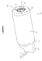
- Figure 1 is a perspective view of protective for a thermal imaging device, according to some embodiments of the present invention.
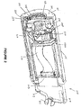
- Figure 2 is a perspective cross-section view of the enclosure of Figure 1 and a thermal imaging device contained within the enclosure, according to some embodiments.
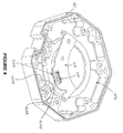
- Figure 3 is a perspective cross-section view of a window assembly of the enclosure shown in Figure 1 , according to some embodiments.
- Figure 4 is an exploded perspective view of the window assembly shown in Figure 3 , according to some embodiments.
- Figure 1 is a perspective view of a protective enclosure 100, according to some embodiments of the present invention; enclosure 100 is adapted to protect an enclosed device from contamination from a surrounding environment.
- Figure 2 is a cross-section view showing a thermal imaging device 500 enclosed within enclosure 100, according to some embodiments.
- Enclosure 100 may be surrounded by an active cooling accessory (not shown), for example, formed from cast aluminum and including internal copper pipes for the circulation of a coolant, which may maintain a specified internal temperature.
- Thermal imaging device 500 is shown as an IR camera module that includes an optics assembly 510, an IR focal plane array (FPA) of microbolometer detector elements 520, and electronics 530, which have the capability to convert the raw IR radiation detected by FPA 520 to temperature and digital image data, according to methods known to those skilled in the art.
- Optics assembly 510 is shown mounted in a flange which is coupled to a heat sink structure in which FPA 520 and associated components are held.
- Electronics 530 are shown mounted on a plurality of stacked printed circuit boards, which are coupled to a connector 213 of an electrical feedthrough assembly 210, via a flex circuit 517.
- Connector 213 may be coupled to a cable conductor 111 ( Figure 1 ), which extends out from enclosure 100, via a passageway 211 ( Figure 2 ) to a remote monitoring station.
- electronics 530 may communicate wirelessly with the remote station, according to methods known to those skilled in the art.
- Figures 1-2 illustrate enclosure 100 including a sidewall 104 that surrounds thermal imaging device 500; electrical feedthrough assembly 210 is shown attached to a first end 101 of sidewall 104, and a window assembly 120 is shown attached to a second end 102 of sidewall 104.
- Figures 1-2 further illustrate window assembly 120, which, according to some embodiments, includes a mounting plate 121, a removable window 123, a removable retaining ring 125, a seal member 122, and a temperature sensor 327 mounted on a printed circuit board 127.
- enclosure 100 is adapted to be mounted at a fixed site in an industrial environment, with window assembly 120 directed toward a target, so that imaging device 500 may monitor the target through window 123.
- Feedthrough assembly 210 is shown including mounting slots 219, to receive mounting bolts, which are located on either side of passageway 211 for cable conductor 111.
- window 123 may be heated, by the ambient environment, to a temperature that is significantly higher than that of device 500 within protective enclosure 100, for example, approximately 10°C to approximately 30°C higher. If the emissivity of window 123 is greater than approximately 0.1 to 0.2, window 123, heated as such, may emit enough radiation to add to the radiation which is emitted from the target and detected by FPA 520, and to thereby introduce an error, for example, as high as 5-10%, into the temperature and digital image data generated by device 500.
- window 123 is formed from silicon, which is approximately 2 mm thick and has an emissivity of approximately 0.3; according to alternate embodiments, window 123 is formed from a thinner and less expensive plastic.
- temperature sensor 327 measures a temperature of window 123, and circuit board 127 transmits the temperature data to the electronics of device 500 as input to a correction term of a calibration algorithm programmed therein.
- Figure 2 illustrates a flex circuit 217 connecting circuit board 127 to the circuitry of device 500, communication therebetween may alternately be wireless, according to methods known to those skilled in the art.
- Figure 3 is a perspective cross-section view of window assembly 120, which is shown separated from the rest of enclosure 100.
- Figure 3 illustrates mounting plate 121 of assembly 120 including a rim, or bezel 323, and an outer shoulder 325, which are both formed in a first side 201 of plate 121.
- Bezel 323 is shown receiving removable window 123
- outer shoulder 325 is shown receiving removable retaining ring 125, such that retaining ring 125 holds window 123 against bezel 323.
- Figure 3 further illustrates a seal member 122, for example, an elastomeric O-ring, which is interposed between retaining ring 125 and window 123, and an optional inner shoulder 322, which surrounds bezel 323 to receive seal member 122.
- retaining ring 125 may be removed, for example, via rotational disengagement at a threaded interface 335 with mounting plate 121, so that seal 122 and/or window 123 may be removed and replaced with a new counterpart, for example, after wear and/or damage thereto.
- FIG. 3 further illustrates circuit board 127 attached to a second side 202 of mounting plate 121 so as to position temperature sensor 327 for measuring the temperature of window 123.
- Temperature sensor 327 may be one of two types: either a direct contact type 327A, for example, a resistance temperature detector (RTD) or thermistor, or a non-contact type 327B, for example, an IR sensor. It should be noted that temperature sensor 327 need not necessarily be mounted on a circuit board, according to alternate embodiments.
- retaining ring 125 when retaining ring 125 is received by outer shoulder 325, and window 123 by bezel 323, retaining ring 125 holds window 123 in thermal conductive contact with mounting plate 121 so that temperature sensor 327 can measure the temperature of window 123 by sensing the temperature of mounting plate 121.
- Mounting plate 121 and retaining ring 125 may be formed from aluminum.
- FIG 4 is an exploded perspective view of window assembly 120, second side 202 of mounting plate 121 is shown including a first portion 427A, with which the first type of temperature sensor 327A comes into thermal conductive contact, when circuit board 127 is attached to second side 202, and a second portion 427B, across from which the second type of temperature sensor 327B is positioned to receive IR radiation therefrom, when circuit board 127 is attached to second side 202.
- window 123 may include an opaque region and circuit board 127 may be attached to second side 202 so as to position the second type of temperature sensor 327B opposite the opaque portion, in order to receive IR radiation therefrom.
- first type of temperature sensor 327A may be positioned to directly contact window 123.
- window 123 when received by bezel 323, need not be held in thermal conductive contact with mounting plate 121.
- Figure 4 further illustrates a connector 417 for coupling temperature sensor 327A or 327B to flex circuit 217 ( Figure 2 ).
- window assembly 120 when attached to end 102 of enclosure sidewall 104, can allow for the passage of IR radiation, from an outside target, into enclosure 100, for detection by device 500, while maintaining the protective nature of enclosure 100, and further provides a correction, via one of two types of temperature sensors 327A, 327B, in order to compensate for radiation emitted from window 123.
- the configuration of window assembly 120 allows for removal and replacement of window 123, and/or seal member 122, without a significant and disruptive maintenance procedure.
Landscapes
- Physics & Mathematics (AREA)
- General Physics & Mathematics (AREA)
- Spectroscopy & Molecular Physics (AREA)
- Radiation Pyrometers (AREA)
- Photometry And Measurement Of Optical Pulse Characteristics (AREA)
- Studio Devices (AREA)
Applications Claiming Priority (1)
| Application Number | Priority Date | Filing Date | Title |
|---|---|---|---|
| US12/492,362 US8753008B2 (en) | 2009-06-26 | 2009-06-26 | Protective enclosure for a thermal imaging device of an industrial monitoring system |
Publications (3)
| Publication Number | Publication Date |
|---|---|
| EP2267423A2 true EP2267423A2 (de) | 2010-12-29 |
| EP2267423A3 EP2267423A3 (de) | 2011-10-26 |
| EP2267423B1 EP2267423B1 (de) | 2017-02-22 |
Family
ID=42833386
Family Applications (1)
| Application Number | Title | Priority Date | Filing Date |
|---|---|---|---|
| EP10251072.4A Active EP2267423B1 (de) | 2009-06-26 | 2010-06-11 | Schutzgehäuse für eine Thermographievorrichtung eines industriellen Überwachungssystems |
Country Status (3)
| Country | Link |
|---|---|
| US (1) | US8753008B2 (de) |
| EP (1) | EP2267423B1 (de) |
| CN (1) | CN101937727B (de) |
Families Citing this family (10)
| Publication number | Priority date | Publication date | Assignee | Title |
|---|---|---|---|---|
| EP2520169B1 (de) * | 2011-04-29 | 2019-12-04 | Electrolux Home Products Corporation N.V. | Backofentür und Backofen |
| US9006655B2 (en) | 2011-12-22 | 2015-04-14 | Fluke Corporation | Thermal imager with protective grid |
| USD718643S1 (en) * | 2013-06-18 | 2014-12-02 | Nutec Solutions, Inc. | PDA-based portable radiation measurement system |
| US20150253857A1 (en) * | 2013-12-23 | 2015-09-10 | Cameron International Corporation | Infrared Gesture Detection for use in Explosion Proof Enclosures |
| US10999536B2 (en) | 2015-06-30 | 2021-05-04 | Rosemount Inc. | Explosion-proof thermal imaging system |
| DE102015223362A1 (de) | 2015-11-25 | 2017-06-01 | Minimax Gmbh & Co. Kg | Explosionsgeschütztes Gehäuse für Mittel zum Senden und Empfangen elektromagnetischer Strahlung |
| US10469715B2 (en) * | 2015-12-31 | 2019-11-05 | Flextronics Ap, Llc | Method and system for heat sinking of camera module |
| US11976549B2 (en) * | 2020-09-21 | 2024-05-07 | Saudi Arabian Oil Company | Monitoring temperatures of a process heater |
| FR3115379B1 (fr) * | 2020-10-16 | 2022-10-21 | Eco Compteur | Dispositif de comptage d’objets |
| CN114500802B (zh) * | 2022-01-21 | 2023-05-05 | 西南科技大学 | 一种γ辐射环境下成像设备的图像去噪方法 |
Family Cites Families (23)
| Publication number | Priority date | Publication date | Assignee | Title |
|---|---|---|---|---|
| US2745028A (en) * | 1948-01-16 | 1956-05-08 | Qualitrol Corp | Pointer bearing for indicating instruments |
| US4113137A (en) * | 1977-09-21 | 1978-09-12 | Cohu, Inc. | Camera housing optical sealing method and device |
| GB2071316B (en) | 1979-09-12 | 1983-11-09 | Raytek Inc | Hand-held digital temperature measuring instrument |
| US4495731A (en) * | 1981-11-04 | 1985-01-29 | Transpec, Inc. | Vehicle hatch mounting assembly |
| US5066142A (en) * | 1990-03-08 | 1991-11-19 | Ivac Corporation | Protective apparatus for a biomedical probe |
| EP0445783B1 (de) * | 1990-03-08 | 1996-02-07 | Ivac Corporation | Thermisch isolierte Sonde |
| JP3367107B2 (ja) * | 1991-10-09 | 2003-01-14 | 富士写真光機株式会社 | レンズ装置のピント補正機構 |
| WO1994000950A1 (en) | 1992-06-19 | 1994-01-06 | Honeywell Inc. | Infrared camera with thermoelectric temperature stabilization |
| FR2743153B1 (fr) | 1995-12-29 | 1998-03-27 | Brun Michel | Hublot de visee, notamment pour controle de la temperature d'objets par thermographie infrarouge |
| JP3144279B2 (ja) | 1995-09-18 | 2001-03-12 | 株式会社村田製作所 | センサ製造用パレット及び赤外線センサの製造方法 |
| JPH11132857A (ja) | 1997-10-28 | 1999-05-21 | Matsushita Electric Works Ltd | 赤外線検出器 |
| US6707044B2 (en) | 2001-05-07 | 2004-03-16 | Flir Systems Ab | Infrared camera system |
| WO2003045234A2 (en) | 2001-11-21 | 2003-06-05 | Optiscan Biomedical Corporation | Method and apparatus for adjusting signal variation of an electronically controlled infrared transmissive window |
| US6837616B2 (en) * | 2002-08-27 | 2005-01-04 | Ircon, Inc. | Method and system for determining the rotational position of a molten metal vehicle |
| AU2003290791A1 (en) * | 2002-11-14 | 2004-06-15 | Donnelly Corporation | Imaging system for vehicle |
| US7332720B2 (en) * | 2003-10-10 | 2008-02-19 | Northrop Grumman Corporation | Cold shield for cryogenic camera |
| US7454050B2 (en) * | 2004-06-18 | 2008-11-18 | Csi Technology, Inc. | Method of automating a thermographic inspection process |
| DE102004050451A1 (de) * | 2004-09-18 | 2006-03-23 | Braun Gmbh | Strahlungsmeßgerät sowie Verfahren und Einrichtung zur Überprüfung der ordnungsgemäßen Funktionsweise des Strahlungsmeßgeräts |
| CA2588855C (en) * | 2004-11-26 | 2009-12-29 | Honda Motor Co., Ltd. | Wire disconnection inspecting device and method |
| US7329869B2 (en) | 2005-09-13 | 2008-02-12 | Autoliv Development Ab | Camera system |
| JP5206233B2 (ja) * | 2007-09-05 | 2013-06-12 | セイコーエプソン株式会社 | 時計および携帯機器 |
| US8201800B2 (en) * | 2008-08-06 | 2012-06-19 | Gentex Corporation | Two ball mount with wiring passage |
| GB201121818D0 (en) * | 2011-12-19 | 2012-02-01 | Certification Information Ltd | Apparatus and method |
-
2009
- 2009-06-26 US US12/492,362 patent/US8753008B2/en active Active
-
2010
- 2010-06-11 EP EP10251072.4A patent/EP2267423B1/de active Active
- 2010-06-28 CN CN201010218051.3A patent/CN101937727B/zh active Active
Non-Patent Citations (1)
| Title |
|---|
| None |
Also Published As
| Publication number | Publication date |
|---|---|
| US8753008B2 (en) | 2014-06-17 |
| CN101937727A (zh) | 2011-01-05 |
| CN101937727B (zh) | 2014-12-17 |
| US20100329306A1 (en) | 2010-12-30 |
| EP2267423B1 (de) | 2017-02-22 |
| EP2267423A3 (de) | 2011-10-26 |
Similar Documents
| Publication | Publication Date | Title |
|---|---|---|
| EP2267423B1 (de) | Schutzgehäuse für eine Thermographievorrichtung eines industriellen Überwachungssystems | |
| CN106331441B (zh) | 改进的防爆热成像系统 | |
| CN102656430B (zh) | 红外线传感器模块 | |
| US9261409B2 (en) | Temperature Control Device | |
| US20220187687A1 (en) | Module Design for Enhanced Radiometric Calibration of Thermal Camera | |
| JP2013013513A (ja) | 放射線画像撮影装置、バッテリユニット、給電ユニット、放射線画像撮影システム及びプログラム | |
| KR101303599B1 (ko) | 적외선 광학계 보정용 진공 흑체 챔버 장치 | |
| WO2015179202A1 (en) | Infrared temperature measurement and stabilization thereof | |
| CN103674276A (zh) | 温度测量仪、尤其手持式红外测量仪 | |
| KR101144778B1 (ko) | 진공 흑체 챔버 | |
| WO2022023748A1 (en) | A thermal imaging system and method | |
| WO2016093491A1 (ko) | 적외선 온도 센서 및 온도 측정 방법 | |
| US20120050539A1 (en) | Camera having a temperature balancing feature | |
| US20200120757A1 (en) | Sensor system upgrade kit for conveyorized oven | |
| WO2017188688A1 (ko) | 온도센서 패키지 | |
| EP1615065B1 (de) | Infrarote Kamera | |
| US20080272453A1 (en) | Optical device cooling apparatus and method | |
| EP3958414B1 (de) | Schaltschrank mit detektor für temperaturanomalien | |
| JP2023153075A (ja) | 放射温度計及び放射温度計冷却ケース | |
| HK1175234A (en) | Infrared sensor module |
Legal Events
| Date | Code | Title | Description |
|---|---|---|---|
| PUAI | Public reference made under article 153(3) epc to a published international application that has entered the european phase |
Free format text: ORIGINAL CODE: 0009012 |
|
| AK | Designated contracting states |
Kind code of ref document: A2 Designated state(s): AL AT BE BG CH CY CZ DE DK EE ES FI FR GB GR HR HU IE IS IT LI LT LU LV MC MK MT NL NO PL PT RO SE SI SK SM TR |
|
| AX | Request for extension of the european patent |
Extension state: BA ME RS |
|
| PUAL | Search report despatched |
Free format text: ORIGINAL CODE: 0009013 |
|
| AK | Designated contracting states |
Kind code of ref document: A3 Designated state(s): AL AT BE BG CH CY CZ DE DK EE ES FI FR GB GR HR HU IE IS IT LI LT LU LV MC MK MT NL NO PL PT RO SE SI SK SM TR |
|
| AX | Request for extension of the european patent |
Extension state: BA ME RS |
|
| RIC1 | Information provided on ipc code assigned before grant |
Ipc: G01J 5/04 20060101AFI20110921BHEP |
|
| 17P | Request for examination filed |
Effective date: 20120425 |
|
| 17Q | First examination report despatched |
Effective date: 20151123 |
|
| RIC1 | Information provided on ipc code assigned before grant |
Ipc: G01J 5/02 20060101ALI20160331BHEP Ipc: G01J 5/00 20060101ALI20160331BHEP Ipc: G01J 5/06 20060101ALI20160331BHEP Ipc: G01J 5/04 20060101AFI20160331BHEP |
|
| GRAP | Despatch of communication of intention to grant a patent |
Free format text: ORIGINAL CODE: EPIDOSNIGR1 |
|
| INTG | Intention to grant announced |
Effective date: 20160525 |
|
| GRAJ | Information related to disapproval of communication of intention to grant by the applicant or resumption of examination proceedings by the epo deleted |
Free format text: ORIGINAL CODE: EPIDOSDIGR1 |
|
| INTC | Intention to grant announced (deleted) | ||
| GRAP | Despatch of communication of intention to grant a patent |
Free format text: ORIGINAL CODE: EPIDOSNIGR1 |
|
| INTG | Intention to grant announced |
Effective date: 20160923 |
|
| GRAS | Grant fee paid |
Free format text: ORIGINAL CODE: EPIDOSNIGR3 |
|
| GRAA | (expected) grant |
Free format text: ORIGINAL CODE: 0009210 |
|
| AK | Designated contracting states |
Kind code of ref document: B1 Designated state(s): AL AT BE BG CH CY CZ DE DK EE ES FI FR GB GR HR HU IE IS IT LI LT LU LV MC MK MT NL NO PL PT RO SE SI SK SM TR |
|
| REG | Reference to a national code |
Ref country code: GB Ref legal event code: FG4D |
|
| REG | Reference to a national code |
Ref country code: CH Ref legal event code: EP |
|
| REG | Reference to a national code |
Ref country code: AT Ref legal event code: REF Ref document number: 869615 Country of ref document: AT Kind code of ref document: T Effective date: 20170315 |
|
| REG | Reference to a national code |
Ref country code: IE Ref legal event code: FG4D |
|
| REG | Reference to a national code |
Ref country code: DE Ref legal event code: R096 Ref document number: 602010040183 Country of ref document: DE |
|
| REG | Reference to a national code |
Ref country code: LT Ref legal event code: MG4D |
|
| REG | Reference to a national code |
Ref country code: FR Ref legal event code: PLFP Year of fee payment: 8 |
|
| REG | Reference to a national code |
Ref country code: NL Ref legal event code: MP Effective date: 20170222 |
|
| REG | Reference to a national code |
Ref country code: AT Ref legal event code: MK05 Ref document number: 869615 Country of ref document: AT Kind code of ref document: T Effective date: 20170222 |
|
| PG25 | Lapsed in a contracting state [announced via postgrant information from national office to epo] |
Ref country code: NO Free format text: LAPSE BECAUSE OF FAILURE TO SUBMIT A TRANSLATION OF THE DESCRIPTION OR TO PAY THE FEE WITHIN THE PRESCRIBED TIME-LIMIT Effective date: 20170522 Ref country code: LT Free format text: LAPSE BECAUSE OF FAILURE TO SUBMIT A TRANSLATION OF THE DESCRIPTION OR TO PAY THE FEE WITHIN THE PRESCRIBED TIME-LIMIT Effective date: 20170222 Ref country code: GR Free format text: LAPSE BECAUSE OF FAILURE TO SUBMIT A TRANSLATION OF THE DESCRIPTION OR TO PAY THE FEE WITHIN THE PRESCRIBED TIME-LIMIT Effective date: 20170523 Ref country code: HR Free format text: LAPSE BECAUSE OF FAILURE TO SUBMIT A TRANSLATION OF THE DESCRIPTION OR TO PAY THE FEE WITHIN THE PRESCRIBED TIME-LIMIT Effective date: 20170222 Ref country code: FI Free format text: LAPSE BECAUSE OF FAILURE TO SUBMIT A TRANSLATION OF THE DESCRIPTION OR TO PAY THE FEE WITHIN THE PRESCRIBED TIME-LIMIT Effective date: 20170222 |
|
| PG25 | Lapsed in a contracting state [announced via postgrant information from national office to epo] |
Ref country code: NL Free format text: LAPSE BECAUSE OF FAILURE TO SUBMIT A TRANSLATION OF THE DESCRIPTION OR TO PAY THE FEE WITHIN THE PRESCRIBED TIME-LIMIT Effective date: 20170222 Ref country code: LV Free format text: LAPSE BECAUSE OF FAILURE TO SUBMIT A TRANSLATION OF THE DESCRIPTION OR TO PAY THE FEE WITHIN THE PRESCRIBED TIME-LIMIT Effective date: 20170222 Ref country code: BG Free format text: LAPSE BECAUSE OF FAILURE TO SUBMIT A TRANSLATION OF THE DESCRIPTION OR TO PAY THE FEE WITHIN THE PRESCRIBED TIME-LIMIT Effective date: 20170522 Ref country code: ES Free format text: LAPSE BECAUSE OF FAILURE TO SUBMIT A TRANSLATION OF THE DESCRIPTION OR TO PAY THE FEE WITHIN THE PRESCRIBED TIME-LIMIT Effective date: 20170222 Ref country code: PT Free format text: LAPSE BECAUSE OF FAILURE TO SUBMIT A TRANSLATION OF THE DESCRIPTION OR TO PAY THE FEE WITHIN THE PRESCRIBED TIME-LIMIT Effective date: 20170622 Ref country code: AT Free format text: LAPSE BECAUSE OF FAILURE TO SUBMIT A TRANSLATION OF THE DESCRIPTION OR TO PAY THE FEE WITHIN THE PRESCRIBED TIME-LIMIT Effective date: 20170222 Ref country code: SE Free format text: LAPSE BECAUSE OF FAILURE TO SUBMIT A TRANSLATION OF THE DESCRIPTION OR TO PAY THE FEE WITHIN THE PRESCRIBED TIME-LIMIT Effective date: 20170222 |
|
| PG25 | Lapsed in a contracting state [announced via postgrant information from national office to epo] |
Ref country code: SK Free format text: LAPSE BECAUSE OF FAILURE TO SUBMIT A TRANSLATION OF THE DESCRIPTION OR TO PAY THE FEE WITHIN THE PRESCRIBED TIME-LIMIT Effective date: 20170222 Ref country code: CZ Free format text: LAPSE BECAUSE OF FAILURE TO SUBMIT A TRANSLATION OF THE DESCRIPTION OR TO PAY THE FEE WITHIN THE PRESCRIBED TIME-LIMIT Effective date: 20170222 Ref country code: EE Free format text: LAPSE BECAUSE OF FAILURE TO SUBMIT A TRANSLATION OF THE DESCRIPTION OR TO PAY THE FEE WITHIN THE PRESCRIBED TIME-LIMIT Effective date: 20170222 Ref country code: RO Free format text: LAPSE BECAUSE OF FAILURE TO SUBMIT A TRANSLATION OF THE DESCRIPTION OR TO PAY THE FEE WITHIN THE PRESCRIBED TIME-LIMIT Effective date: 20170222 Ref country code: IT Free format text: LAPSE BECAUSE OF FAILURE TO SUBMIT A TRANSLATION OF THE DESCRIPTION OR TO PAY THE FEE WITHIN THE PRESCRIBED TIME-LIMIT Effective date: 20170222 |
|
| REG | Reference to a national code |
Ref country code: DE Ref legal event code: R097 Ref document number: 602010040183 Country of ref document: DE |
|
| PG25 | Lapsed in a contracting state [announced via postgrant information from national office to epo] |
Ref country code: PL Free format text: LAPSE BECAUSE OF FAILURE TO SUBMIT A TRANSLATION OF THE DESCRIPTION OR TO PAY THE FEE WITHIN THE PRESCRIBED TIME-LIMIT Effective date: 20170222 Ref country code: SM Free format text: LAPSE BECAUSE OF FAILURE TO SUBMIT A TRANSLATION OF THE DESCRIPTION OR TO PAY THE FEE WITHIN THE PRESCRIBED TIME-LIMIT Effective date: 20170222 Ref country code: DK Free format text: LAPSE BECAUSE OF FAILURE TO SUBMIT A TRANSLATION OF THE DESCRIPTION OR TO PAY THE FEE WITHIN THE PRESCRIBED TIME-LIMIT Effective date: 20170222 |
|
| PLBE | No opposition filed within time limit |
Free format text: ORIGINAL CODE: 0009261 |
|
| STAA | Information on the status of an ep patent application or granted ep patent |
Free format text: STATUS: NO OPPOSITION FILED WITHIN TIME LIMIT |
|
| 26N | No opposition filed |
Effective date: 20171123 |
|
| PG25 | Lapsed in a contracting state [announced via postgrant information from national office to epo] |
Ref country code: MC Free format text: LAPSE BECAUSE OF FAILURE TO SUBMIT A TRANSLATION OF THE DESCRIPTION OR TO PAY THE FEE WITHIN THE PRESCRIBED TIME-LIMIT Effective date: 20170222 |
|
| REG | Reference to a national code |
Ref country code: CH Ref legal event code: PL |
|
| PG25 | Lapsed in a contracting state [announced via postgrant information from national office to epo] |
Ref country code: SI Free format text: LAPSE BECAUSE OF FAILURE TO SUBMIT A TRANSLATION OF THE DESCRIPTION OR TO PAY THE FEE WITHIN THE PRESCRIBED TIME-LIMIT Effective date: 20170222 |
|
| REG | Reference to a national code |
Ref country code: IE Ref legal event code: MM4A |
|
| PG25 | Lapsed in a contracting state [announced via postgrant information from national office to epo] |
Ref country code: CH Free format text: LAPSE BECAUSE OF NON-PAYMENT OF DUE FEES Effective date: 20170630 Ref country code: LI Free format text: LAPSE BECAUSE OF NON-PAYMENT OF DUE FEES Effective date: 20170630 Ref country code: IE Free format text: LAPSE BECAUSE OF NON-PAYMENT OF DUE FEES Effective date: 20170611 Ref country code: LU Free format text: LAPSE BECAUSE OF NON-PAYMENT OF DUE FEES Effective date: 20170611 |
|
| REG | Reference to a national code |
Ref country code: BE Ref legal event code: MM Effective date: 20170630 |
|
| REG | Reference to a national code |
Ref country code: FR Ref legal event code: PLFP Year of fee payment: 9 |
|
| PG25 | Lapsed in a contracting state [announced via postgrant information from national office to epo] |
Ref country code: BE Free format text: LAPSE BECAUSE OF NON-PAYMENT OF DUE FEES Effective date: 20170630 |
|
| PG25 | Lapsed in a contracting state [announced via postgrant information from national office to epo] |
Ref country code: MT Free format text: LAPSE BECAUSE OF NON-PAYMENT OF DUE FEES Effective date: 20170611 |
|
| PG25 | Lapsed in a contracting state [announced via postgrant information from national office to epo] |
Ref country code: HU Free format text: LAPSE BECAUSE OF FAILURE TO SUBMIT A TRANSLATION OF THE DESCRIPTION OR TO PAY THE FEE WITHIN THE PRESCRIBED TIME-LIMIT; INVALID AB INITIO Effective date: 20100611 |
|
| PG25 | Lapsed in a contracting state [announced via postgrant information from national office to epo] |
Ref country code: CY Free format text: LAPSE BECAUSE OF NON-PAYMENT OF DUE FEES Effective date: 20170222 |
|
| PG25 | Lapsed in a contracting state [announced via postgrant information from national office to epo] |
Ref country code: MK Free format text: LAPSE BECAUSE OF FAILURE TO SUBMIT A TRANSLATION OF THE DESCRIPTION OR TO PAY THE FEE WITHIN THE PRESCRIBED TIME-LIMIT Effective date: 20170222 |
|
| PG25 | Lapsed in a contracting state [announced via postgrant information from national office to epo] |
Ref country code: TR Free format text: LAPSE BECAUSE OF FAILURE TO SUBMIT A TRANSLATION OF THE DESCRIPTION OR TO PAY THE FEE WITHIN THE PRESCRIBED TIME-LIMIT Effective date: 20170222 |
|
| PG25 | Lapsed in a contracting state [announced via postgrant information from national office to epo] |
Ref country code: AL Free format text: LAPSE BECAUSE OF FAILURE TO SUBMIT A TRANSLATION OF THE DESCRIPTION OR TO PAY THE FEE WITHIN THE PRESCRIBED TIME-LIMIT Effective date: 20170222 Ref country code: IS Free format text: LAPSE BECAUSE OF FAILURE TO SUBMIT A TRANSLATION OF THE DESCRIPTION OR TO PAY THE FEE WITHIN THE PRESCRIBED TIME-LIMIT Effective date: 20170622 |
|
| PGFP | Annual fee paid to national office [announced via postgrant information from national office to epo] |
Ref country code: DE Payment date: 20250626 Year of fee payment: 16 |
|
| PGFP | Annual fee paid to national office [announced via postgrant information from national office to epo] |
Ref country code: GB Payment date: 20250617 Year of fee payment: 16 |
|
| PGFP | Annual fee paid to national office [announced via postgrant information from national office to epo] |
Ref country code: FR Payment date: 20250624 Year of fee payment: 16 |