EP2266771B1 - Vorrichtung und Verfahren zum Kühlen und Eintragen eines riesel- oder pulverförmigen Stoffstroms in einen Lagerbehälter - Google Patents
Vorrichtung und Verfahren zum Kühlen und Eintragen eines riesel- oder pulverförmigen Stoffstroms in einen Lagerbehälter Download PDFInfo
- Publication number
- EP2266771B1 EP2266771B1 EP20100165079 EP10165079A EP2266771B1 EP 2266771 B1 EP2266771 B1 EP 2266771B1 EP 20100165079 EP20100165079 EP 20100165079 EP 10165079 A EP10165079 A EP 10165079A EP 2266771 B1 EP2266771 B1 EP 2266771B1
- Authority
- EP
- European Patent Office
- Prior art keywords
- cooling
- nozzle
- cooling medium
- medium
- mixing chamber
- Prior art date
- Legal status (The legal status is an assumption and is not a legal conclusion. Google has not performed a legal analysis and makes no representation as to the accuracy of the status listed.)
- Active
Links
Images

Classifications
-
- B—PERFORMING OPERATIONS; TRANSPORTING
- B28—WORKING CEMENT, CLAY, OR STONE
- B28C—PREPARING CLAY; PRODUCING MIXTURES CONTAINING CLAY OR CEMENTITIOUS MATERIAL, e.g. PLASTER
- B28C7/00—Controlling the operation of apparatus for producing mixtures of clay or cement with other substances; Supplying or proportioning the ingredients for mixing clay or cement with other substances; Discharging the mixture
- B28C7/0007—Pretreatment of the ingredients, e.g. by heating, sorting, grading, drying, disintegrating; Preventing generation of dust
- B28C7/0023—Pretreatment of the ingredients, e.g. by heating, sorting, grading, drying, disintegrating; Preventing generation of dust by heating or cooling
- B28C7/0038—Cooling, e.g. using ice
-
- B—PERFORMING OPERATIONS; TRANSPORTING
- B65—CONVEYING; PACKING; STORING; HANDLING THIN OR FILAMENTARY MATERIAL
- B65G—TRANSPORT OR STORAGE DEVICES, e.g. CONVEYORS FOR LOADING OR TIPPING, SHOP CONVEYOR SYSTEMS OR PNEUMATIC TUBE CONVEYORS
- B65G53/00—Conveying materials in bulk through troughs, pipes or tubes by floating the materials or by flow of gas, liquid or foam
- B65G53/34—Details
- B65G53/52—Adaptations of pipes or tubes
- B65G53/526—Adaptations of pipes or tubes with means for special treatment to facilitate transport
-
- C—CHEMISTRY; METALLURGY
- C04—CEMENTS; CONCRETE; ARTIFICIAL STONE; CERAMICS; REFRACTORIES
- C04B—LIME, MAGNESIA; SLAG; CEMENTS; COMPOSITIONS THEREOF, e.g. MORTARS, CONCRETE OR LIKE BUILDING MATERIALS; ARTIFICIAL STONE; CERAMICS; REFRACTORIES; TREATMENT OF NATURAL STONE
- C04B40/00—Processes, in general, for influencing or modifying the properties of mortars, concrete or artificial stone compositions, e.g. their setting or hardening ability
- C04B40/06—Inhibiting the setting, e.g. mortars of the deferred action type containing water in breakable containers ; Inhibiting the action of active ingredients
- C04B40/0683—Inhibiting the setting, e.g. mortars of the deferred action type containing water in breakable containers ; Inhibiting the action of active ingredients inhibiting by freezing or cooling
-
- F—MECHANICAL ENGINEERING; LIGHTING; HEATING; WEAPONS; BLASTING
- F25—REFRIGERATION OR COOLING; COMBINED HEATING AND REFRIGERATION SYSTEMS; HEAT PUMP SYSTEMS; MANUFACTURE OR STORAGE OF ICE; LIQUEFACTION SOLIDIFICATION OF GASES
- F25D—REFRIGERATORS; COLD ROOMS; ICE-BOXES; COOLING OR FREEZING APPARATUS NOT OTHERWISE PROVIDED FOR
- F25D3/00—Devices using other cold materials; Devices using cold-storage bodies
- F25D3/10—Devices using other cold materials; Devices using cold-storage bodies using liquefied gases, e.g. liquid air
Definitions
- the invention relates to a device for cooling a trickle or powdery material flow, in which the material flow is fed via a supply line connecting a storage tank to a storage container and brought into contact with a nozzle leading from the opening into a nozzle opening with a supplied from a cooling medium supply cryogenic cooling medium becomes.
- the invention further relates to a corresponding method.
- Such devices are known.
- aggregates for example cement or sand
- the aggregate is usually brought into direct contact with liquid nitrogen or liquid carbon dioxide as the cooling medium and thereby cooled.
- From the DE 40 10 045 A1 is a method for cooling a powdered material stream, in particular cement, during its pneumatic conveying known in a silo.
- the material flow is fed to the silo via a delivery line, in which a Venturi nozzle is installed.
- a delivery line in which a Venturi nozzle is installed.
- the venturi already at the beginning Provide the delivery line to ensure the longest possible mixing distance in the delivery line.
- the disadvantage of this article is that it comes to the phase transition of the nitrogen and thus to a high evolution of gas at the contact point when the liquid nitrogen in the Venturi nozzle to the liquid to be cooled. This leads to a short-term blocking of the material flow in the delivery line.
- a device and a method for cooling cement according to the preamble of claims 1 and 8 is described in which a cryogenic cooling medium and the cement to be cooled are introduced simultaneously at an externally mixing two-fluid nozzle in the silo.
- the two-fluid nozzle comprises concentrically arranged mouth openings for the cement and for the cooling medium.
- the object of the invention is therefore to provide a way to enter and cool streams, in particular for entering and cooling of cement, which allows efficient cooling and at the same time reduces the burden on people and the environment.
- a device characterized in that the nozzle is equipped with a mixing chamber into which the delivery line opens with a mouth portion, and at which the at least one cooling medium supply inclined with an orifice portion at an acute angle to the longitudinal axis of the supply line arranged is that one Cooling medium flow is discharged from the cooling medium supply with a directional component in the direction of the nozzle opening.
- the delivery line and the cooling medium supply are thus fluidly connected to each other only at the nozzle, which opens into the interior of the storage container (silo). Both streams thus only come into direct contact with the nozzle at the nozzle. The mixture begins inside the nozzle and continues after discharge of the streams from the nozzle outside the nozzle. The mixing of the two streams, and thus the phase transition of the cooling medium, so at least for a substantial part only outside of the nozzle and thus the delivery line instead.
- a good cooling effect is achieved, on the other hand, the known from the prior art, caused by a phase transition of the cooling medium in the interior of the delivery line impulsive disturbances in the mass transfer and thus the intermittent blowing off of dusts are avoided.
- the substances come into contact with each other so intensively that a good heat transfer is ensured and the enthalpy of the cooling medium is used well.
- a cooling medium flow spirally enveloping the flow of material leaves the nozzle at the nozzle orifice together with the flow of material. This avoids direct contact of the material flow with the walls of the nozzle, which would otherwise be abrasive and reduce the life of the nozzle.
- the angle at which the supply lines for the cooling medium are inclined with respect to the longitudinal axis of the delivery line is determined according to the respective requirements.
- the preferred cryogenic cooling medium is liquid or cold gaseous nitrogen or liquid or cold gaseous carbon dioxide.
- An advantageous development of the invention provides that the mouth portion of the delivery line at its entry into the mixing chamber, a nozzle-like constriction, a so-called confuser.
- the confuser reduces the flow cross-section of the material flow and thereby increases the speed of the jet emerging from the two-substance nozzle, stabilizes it with it and thus extends the mixing distance of solid and cooling medium.
- the high velocity of the material flow leads to a negative pressure in the mixing chamber, the suction effect of which promotes the introduction of the cooling medium into the mixing chamber.
- the mouth portion of the delivery line in the mixing chamber and the nozzle opening are arranged coaxially to each other, wherein the diameter of the circular nozzle opening is larger than the diameter of the likewise circular mouth opening of the delivery line into the mixing chamber.
- the nozzle opening is thus wider than the flow of the material to be cooled which emerges during operation of the device from the mouth opening of the delivery line. In the area between the material flow and the nozzle opening thus remains an open annular space which is filled by the enveloping cooling medium flow.
- At least two supply lines are provided for the cooling medium, which open at equal angular intervals with their mouth sections in the mixing chamber.
- an advantageous embodiment of the invention provides that the feed line for the cooling medium opens into the mixing chamber as a ring nozzle arranged frustoconically around its mouth section of the feed line with its mouth section.
- the supply line for the cooling medium is equipped with a shut-off valve, which automatically closes when falling below a predetermined pressure. This prevents that when switching off the device components of the Material flow or the ambient atmosphere, such as humidity, in the cooling medium supply, or the cooling medium supply, penetrate and can lead to icing.
- a particularly preferred embodiment of the invention provides that a control device regulates the volume flows of material to be cooled and the cooling medium as a function of physical or chemical parameters.
- the control takes place, for example, as a function of the measured temperature of the supplied substance or the target temperature of the cooled substance and / or of the dust loading of an exhaust gas flow discharged from the silo. This optimizes the use of cooling medium, minimizes the discharge of solids from the silo and thus reduces the burden on people and the environment.
- the object of the invention is also achieved by a method for cooling a powdery substance according to claim 8, wherein the material flow via a supply tank connected to a storage tank conveying line and at a opening into the storage container with a nozzle opening nozzle with a cryogenic cooling medium in contact is brought, and the invention is characterized in that the material flow is discharged as a particle flow and the cooling medium at least partially as a particle flow surrounding the flow of cooling medium through the nozzle opening.
- the cooling medium flow surrounding the particle jet in particular prevents abrasive damage to the nozzle due to the exiting particle flow and thus prolongs the service life of the nozzle. At the same time it causes an intimate mixing of cooling medium and material flow after exiting the nozzle orifice.
- a dedusting filter 11 is arranged at the silo head.
- the feed takes place from the delivery vehicle 1 via a supply line 2, which is connected via a connection with a delivery line 9.
- the delivery line 9 opens at a nozzle 8 in the silo 10 a.
- a cooling medium, liquid or cold gaseous nitrogen in the exemplary embodiment is guided via a coolant line 3 through a flow meter 4 to a control valve 6, which is controlled by a control unit 5 to a specific, fixed or set depending on measured parameters flow rate. Subsequently, the cooling medium is transported via a cooling medium line 7 to the nozzle 8.
- the control unit 5 is in data communication with a sensor for detecting the temperature of the cement stored in the silo 10 and / or a sensor for detecting the solids content in the exhaust air fed to the dedusting filter 11 and thus enables a function of predetermined values Cement temperature or the solids content controlled supply of the cooling medium.
- nozzle 8 has a mixing chamber 14, in which a feed line 15 for the flow of material and twodemediumszu exchangeen 16,17 open.
- the supply line 15 for the material flow has a flange 18 for connecting the delivery line 9.
- the cooling medium supply 16, 17 also have flanges 19, 20 on which - not shown here - supply lines are fastened, which are in fluid communication with the cooling medium line 7 ,
- the circular cross-section supply line 15 narrows at its front portion, the diameter in the region of the mouth opening 21 reaches its minimum.
- the Confusor formed in this way serves to increase the flow velocity of the guided through the feed line 15 substance.
- the nozzle 8 has a coaxial with the inlet 15 arranged mouth portion with an outlet opening 22 whose preferably circular cross-section has a larger diameter than the supply line 15 in the region of its mouth opening 21.
- the mouth section of the nozzle 8 is firmly but detachably connected to a wall 24 of the silo 10 in the region of a feed opening 25 provided there.
- the value of the angle ⁇ between the axis 26 of the feed line 15 and the axis 27 of the cooling medium supply 16 has a value between 10 ° and 45 °, preferably between 20 ° and 30 °, for example 22.5 °.
- non-return valves 28, 29 are arranged, which automatically close when falling below a predetermined pressure difference between the (higher) pressure in the cooling medium line 7 connected to the cooling medium feeds 16, 17 and the (lower) pressure inside the mixing chamber 14 , In this way it is prevented that after completion of the filling of the silo 10 with cement cement particles or humidity in the cooling medium supply 16,17 penetrate and clog or freeze.
- the check valves 28, 29 are a type valve of the type described in US Pat DE 10 2006 027 561 A1 is described.
- a pulverulent substance for example cement
- a pulverulent substance is conveyed pneumatically from the delivery vehicle 1 via the supply line 2 and the delivery line 9 to the nozzle 8 and flows via the supply line 15 into the mixing chamber 14.
- the material flow forms a particle jet extending through the mixing chamber 14 and penetrating deep into the interior of the silo 10 in front of the outlet opening 22 of the nozzle 8.
- About the Coolant medium line 7 passes through a precisely metered amount of a cooling medium via the control valve 6 in theharimediumszu Adjusten 16, 17 and from there into the mixing chamber 14 of the nozzle 8.
- the supply of the cooling medium via two separate cooling medium feeds 16, 17 leads to a rotating movement of the cooling medium flow about the longitudinal axis 26 within the nozzle 8 and then to a rotating in itself movement of the cooling medium jet in the region in front of the outlet opening 22 of the nozzle 8.
- the substance jets are stabilized and thus the mixing section, within which the cement is in contact with the cooling medium, is extended. In this way, an efficient and uniform heat transfer from the cooling medium is guaranteed to the flow.
- a liquefied cryogenic cooling medium and cold gaseous cooling media can be used, such as a gas, for example nitrogen, argon or carbon dioxide, which is maintained at a temperature which is equal to or slightly more than the boiling point at the corresponding pressure conditions in the cooling medium supply 7 becomes.
- a gas for example nitrogen, argon or carbon dioxide
- carbon dioxide or another pressure-liquefied gas can be used, which is transported in the liquid state under pressure to the two-fluid nozzle 8 and is expanded in the two-fluid nozzle 8 or before its mouth with cold development.
- a pressure line is provided instead of the heat-insulated line 7, which allows the transport of liquid carbon dioxide at ambient temperature.
- a device for swirl generation can be provided, which stabilizes the material flow and the cooling medium jet surrounding it and prolongs the distance of the mixing of the two material flows.
- the device according to the invention is not limited to the cooling of cement but can generally be used for cooling powdered or free-flowing substances with a cryogenic cooling medium.
Landscapes
- Chemical & Material Sciences (AREA)
- Engineering & Computer Science (AREA)
- Ceramic Engineering (AREA)
- Mechanical Engineering (AREA)
- Materials Engineering (AREA)
- Structural Engineering (AREA)
- Organic Chemistry (AREA)
- Dispersion Chemistry (AREA)
- Acyclic And Carbocyclic Compounds In Medicinal Compositions (AREA)
Description
- Die Erfindung betrifft eine Vorrichtung zum Kühlen eines riesel- oder pulverförmigen Stoffstroms, bei der der Stoffstrom über eine einen Vorratstank mit einem Lagerbehälter verbindende Förderleitung zugeführt und an einer in den Lagerbehälter mit einer Düsenöffnung ausmündenden Düse mit einem aus einer Kühlmediumszuführung herangeführten kryogenen Kühlmedium in Kontakt gebracht wird. Die Erfindung betrifft des Weiteren ein entsprechendes Verfahren.
- Derartige Vorrichtungen sind bekannt. So ist es beispielsweise bei der Herstellung von Frischbeton nicht selten erforderlich, Zuschlagstoffe, beispielsweise Zement oder Sand, vor der Zumischung zu kühlen, um zu hohe Temperaturen beim Abbinden zu verhindern. Dabei wird der Zuschlagsstoff üblicherweise mit Flüssigstickstoff oder flüssigem Kohlendioxid als Kühlmedium in direkten Kontakt gebracht und dadurch gekühlt.
- Aus der
DE 36 23 726 A1 ist bekannt, Zement und flüssigen Stickstoff über separate Zuleitungen in einen Lagerbehälter, beispielsweise ein Silo, einzusprühen. Beim Kontakt mit dem Zement verdampft der Stickstoff und wird als Gas mit dem Abluftstrom ausgetragen. Mit diesem Verfahren kann jedoch eine ausreichende Kühlung nicht erzielt werden, da bei der getrennten Zuführung von Zement und Stickstoff ein nur unzureichender Wärmekontakt zwischen beiden Stoffen hergestellt wird. Ein großer Teil des eingesetzten Stickstoffs entweicht damit ungenutzt, und das kalte Stickstoffabgas kann leicht eine Vereisung eines dem Silo zugeordneten Entstaubungsfilters bewirken. - Aus der
DE 40 10 045 A1 ist ein Verfahren zur Kühlung eines pulverförmigen Stoffstroms, insbesondere Zement, während dessen pneumatischer Förderung in ein Silo bekannt. Der Stoffstrom wird dabei dem Silo über eine Förderleitung zugeführt, in der eine Venturidüse eingebaut ist. An der Venturidüse mündet eine Kühlmittelzuleitung ein, über die flüssiger Stickstoff in den Stoffstrom eingebracht wird. Als besonders vorteilhaft wird bei diesem Gegenstand angesehen, die Venturidüse bereits am Anfang der Förderleitung vorzusehen, um eine möglichst lange Mischstrecke in der Förderleitung zu gewährleisten. Nachteilig bei diesem Gegenstand ist jedoch, dass es beim Auftreffen des flüssigen Stickstoffs auf die zu kühlende Substanz in der Venturidüse zum Phasenübergang des Stickstoffs und damit zu einer hohen Gasentwicklung an der Kontaktstelle kommt. Dies führt zu einer kurzzeitigen Sperrung des Stoffsstroms in der Förderleitung. Erst nach dem Abbau der Gasblase kann der Feststofftransport wieder aufgenommen werden, wird jedoch sogleich aufgrund der erneuten Verdampfung von Flüssigstickstoff beim Kontakt mit noch warmem zugeführtem Feststoff wieder gestoppt. Dieser Vorgang wiederholt sich laufend und führt in der Folge zu einem stoßweisen Abblasen von Stäuben über die Abluftleitung des Lagersilos. Hierdurch geht Substanz verloren und es kommt zu einer nicht unerheblichen Belastung von Beschäftigten und Umwelt. - In der
DE 10 2005 037 081 A1 wird eine Vorrichtung und ein Verfahren zum Kühlen von Zement gemäß dem Oberbegriff der Ansprüche 1 und 8 beschrieben, bei dem ein kryogenes Kühlmedium und der zu kühlende Zement gleichzeitig an einer außenmischenden Zweistoffdüse in das Silo eingetragen werden. Die Zweistoffdüse umfasst konzentrisch zueinander angeordnete Mündungsöffnungen für den Zement und für das Kühlmedium. Durch das Prinzip der Außenmischung wird das zuvor genannte Problem des stoßweisen Abblasens zuverlässig vermieden; Jedoch ist die Durchmischung von Stoff und Kühlmedium und damit die Effizienz der Kühlung noch verbesserungsfähig. - Aufgabe der Erfindung ist daher, eine Möglichkeit zum Eintragen und Kühlen von Stoffströmen, insbesondere zum Eintragen und Kühlen von Zement, anzugeben, die eine effiziente Kühlung ermöglicht und zugleich die Belastung von Mensch und Umwelt reduziert.
- Diese Aufgabe wird bei einer Vorrichtung gemäß Anspruch 1 dadurch gelöst, dass die Düse mit einer Mischkammer ausgerüstet ist, in die die Förderleitung mit einem Mündungsabschnitt einmündet, und an der die wenigstens eine Kühlmediumszuführung mit einem Mündungsabschnitt derart in einem spitzen Winkel zur Längsachse der Zuleitung geneigt angeordnet ist, dass ein Kühlmediumsstrom aus der Kühlmediumszuführung mit einer Richtungskomponente in Richtung der Düsenöffnung ausgestoßen wird.
- Die Förderleitung und die Kühlmediumszuführung sind somit erst an der Düse miteinander strömungsverbunden, die in das Innere des Lagerbehälters (Silo) einmündet. Beide Stoffströme kommen also erst unmittelbar an der Düse in Wärmekontakt. Die Mischung beginnt im Düseninnern und setzt sich nach dem Austragen der Stoffströme aus der Düse außerhalb der Düse fort. Die Durchmischung beider Stoffströme, und damit auch der Phasenübergang des Kühlmediums, finden also zumindest zu einem wesentlichen Teil erst außerhalb der Düse und damit der Förderleitung statt. Dadurch wird einerseits eine gute Kühlwirkung erzielt, zum anderen werden die aus dem Stand der Technik bekannten, durch einen Phasenübergang des Kühlmediums im Innern der Förderleitung verursachten impulsartigen Störungen beim Stofftransport und damit auch das stoßweise Abblasen von Stäuben vermieden. Gleichwohl kommen die Stoffe so intensiv miteinander in Kontakt, dass eine gute Wärmeübertragung gewährleistet und die Enthalpie des Kühlmediums gut genutzt wird. Durch die spitzwinklige, also mit einer Komponente in Richtung zur Düsenmündung ausgestaltete Strömungsführung des Kühlmediums bildet sich ein den Stoffstrom spiralig umhüllender Kühlmediumsstrom aus, der gemeinsam mit dem Stoffstrom die Düse an der Düsenmündung verlässt. Dadurch wird ein direkter Kontakt des Stoffstroms mit den Wänden der Düse vermieden, der ansonsten abrasiv wirken und die Lebensdauer der Düse vermindern würde. Der Winkel, mit dem die Zuleitungen für das Kühlmedium gegenüber der Längsachse der Förderleitung geneigt sind, bestimmt sich nach den jeweiligen Erfordernissen. Je steiler das Kühlmedium in den Stoffstrom eingetragen wird, desto schneller werden die Stoffe miteinander vermischt, desto geringer ist jedoch die Ausbildung des den Stoffstrom einhüllenden Kühlmediumsstroms. Besonders günstige Ergebnisse werden bei Winkeln zwischen 10° und 45°, besonders bevorzugt 20° und 30° erzielt. Als bevorzugtes kryogenes Kühlmedium kommt flüssiger oder kalter gasförmiger Stickstoff oder flüssiges oder kaltes gasförmiges Kohlendioxid zum Einsatz.
- Eine vorteilhafte Weiterbildung der Erfindung sieht vor, dass der Mündungsabschnitt der Förderleitung an ihrem Eintritt in die Mischkammer eine düsenartige Verengung, einen sogenannten Konfusor, aufweist. Der Konfusor verringert den Strömungsquerschnitt des Stoffstroms und erhöht dadurch die Geschwindigkeit des aus der Zweistoffdüse austretenden Strahls, stabilisiert diesen damit und verlängert so die Mischstrecke von Feststoff und Kühlmedium. Zudem führt die hohe Geschwindigkeit des Stoffstroms zu einem Unterdruck in der Mischkammer, dessen Saugwirkung das Eintragen des Kühlmediums in die Mischkammer unterstützt.
- Zweckmäßigerweise sind der Mündungsabschnitt der Förderleitung in die Mischkammer und die Düsenöffnung koaxial zueinander angeordnet, wobei der Durchmesser der kreisförmigen Düsenöffnung größer ist als der Durchmesser der gleichfalls kreisförmigen Mündungsöffnung der Förderleitung in die Mischkammer. Die Düsenöffnung ist damit breiter als der im Betrieb der Vorrichtung aus der Mündungsöffnung der Förderleitung austretende Strom des zu kühlenden Stoffes. In den Bereich zwischen Stoffstrom und Düsenöffnung verbleibt somit ein offener Ringraum, der vom umhüllenden Kühlmediumsstrom ausgefüllt wird.
- Bevorzugt sind wenigstens zwei Zuleitungen für das Kühlmedium vorgesehen, die in gleichen Winkelabständen mit ihren Mündungsabschnitten in die Mischkammer einmünden. Dadurch gelingt eine besonders effiziente Ausgestaltung des den Stoffstrom spiralförmig umhüllenden Kühlmediumsstroms.
- Alternativ oder ergänzend zu der vorgenannten Ausführungsform mehrerer in gleichen Winkelabständen um den Mündungsabschnitt der Förderleitung angeordneter Kühlmediumszuführungen sieht eine vorteilhafte Ausgestaltung der Erfindung vor, dass die Zuleitung für das Kühlmedium als eine mit ihrem Mündungsabschnitt kegelstumpfförmig um den Mündungsabschnitt der Förderleitung angeordnete Ringdüse in die Mischkammer einmündet. Für den Eintragswinkel des über die kegelstumpfartige Zuleitung eingetragenen Kühlmediumsstroms gilt das oben über die bevorzugten Winkelmaße für den Kühlmediumseintrag Gesagte.
- Vorteilhafterweise ist die Zuleitung für das Kühlmedium mit einem Sperrventil ausgerüstet, das bei Unterschreiten eines vorgegebenen Druckes selbsttätig schließt. Dadurch wird verhindert, dass beim Abschalten der Einrichtung Bestandteile des Stoffstroms oder der Umgebungsatmosphäre, wie beispielsweise Luftfeuchtigkeit, in die Kühlmediumszuführung, bzw. die Kühlmediumszuführungen, eindringen und dort zu Vereisungen führen kann.
- Eine besonders bevorzugte Ausgestaltung der Erfindung sieht vor, dass eine Regeleinrichtung die Volumenströme von zu kühlendem Stoff und Kühlmedium in Abhängigkeit von physikalischen oder chemischen Parametern regelt. Die Regelung erfolgt beispielsweise in Abhängigkeit von der gemessenen Temperatur des zugeführten Stoffes oder der Zieltemperatur des gekühlten Stoffes und/oder von der Staubbeladung eines aus dem Silo abgeführten Abgasstromes. Damit wird der Einsatz an Kühlmedium optimiert, der Feststoffaustrag aus dem Silo minimiert und damit die Belastung von Mensch und Umwelt reduziert.
- Die Aufgabe der Erfindung wird auch durch ein Verfahren zum Kühlen eines pulverförmigen Stoffs gemäß Anspruch 8 gelöst, bei dem der Stoffstrom über eine einen Vorratstank mit einem Lagerbehälter verbindende Förderleitung zugeführt und an einer in den Lagerbehälter mit einer Düsenöffnung ausmündenden Düse mit einem kryogenen Kühlmedium in Kontakt gebracht wird, und das erfindungsgemäß dadurch gekennzeichnet ist, dass der Stoffstrom als ein Partikelstrom und das Kühlmedium zumindest teilweise als ein den Partikelstrom umhüllender Kühlmediumsstrom durch die Düsenöffnung ausgetragen wird. Der den Partikelstrahl umhüllende Kühlmediumsstrom verhindert insbesondere abrasive Schädigungen der Düse durch den austretenden Partikelstrom und verlängert damit die Lebensdauer der Düse. Zugleich bewirkt er eine innige Durchmischung von Kühlmedium und Stoffstrom nach dem Austritt aus der Düsenmündung.
- Bevorzugt kommt als zu kühlender Stoffstrom ein Baustoff, beispielsweise Zement, und als Kühlmedium flüssiger oder kalter gasförmiger Stickstoff oder flüssiges oder kaltes gasförmiges Kohlendioxid zum Einsatz.
- Anhand der Zeichnungen soll ein Ausführungsbeispiel der Erfindung näher erläutert werden. In schematischen Ansichten zeigen:
-
Fig. 1 : Eine erfindungsgemäße Vorrichtung zum Kühlen von Zement und -
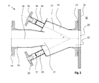
Fig. 2 : Eine in der Vorrichtung nachFig. 1 eingesetzte Zweistoffdüse zum Eintragen von Zement und Kühlmedium. - Bei der erfindungsgemäßen Vorrichtung nach
Fig. 1 wird ein pulverförmiger Stoff, im Ausführungsbeispiel Zement, aus einem Lieferfahrzeug 1 pneumatisch in ein Silo 10 eingespeist. Am Silokopf ist ein Entstaubungsfilter 11 angeordnet. Die Einspeisung erfolgt vom Lieferfahrzeug 1 über eine Zuleitung 2, die über einen Anschluss mit einer Förderleitung 9 verbunden ist. Die Förderleitung 9 mündet an einer Düse 8 in das Silo 10 ein. Ein Kühlmedium, im Ausführungsbeispiel flüssiger oder kalter gasförmiger Stickstoff, wird über eine Kühlmediumsleitung 3 durch einen Durchflussmesser 4 zu einem Steuerventil 6 geführt, das mittels einer Steuereinheit 5 auf eine bestimmte, fest eingestellte oder in Abhängigkeit von gemessenen Parametern festgelegte Durchflussmenge geregelt wird. Anschließend wird das Kühlmedium über eine Kühlmediumsleitung 7 zur Düse 8 transportiert. Bei den Kühlmediumsleitungen 3, 7 handelt es sich im Falle der Kühlung mit einem tiefkalten kryogenen Medium, wie beispielsweise flüssiger Stickstoff, um wärmeisolierte Leitungen, im Falle eines druckverflüssigten kryogenen Mediums, wie flüssiges Kohlendioxid, um druckfeste Leitungen. Die Steuereinheit 5 steht in hier nicht gezeigter Weise mit einem Sensor zur Erfassung der Temperatur des im Silo 10 gelagerten Zements und/oder einem Sensor zur Erfassung des Feststoffanteils in der dem Entstaubungsfilter 11 zugeführten Abluft in Datenverbindung und ermöglicht so eine in Abhängigkeit von vorgegebenen Werten der Zementtemperatur bzw. des Feststoffanteils geregelte Zuführung des Kühlmediums. - Die in
Fig. 2 dargestellte Düse 8 weist eine Mischkammer 14 auf, in die eine Zuleitung 15 für den Stoffstrom sowie zwei Kühlmediumszuführungen 16,17 einmünden. Die Zuleitung 15 für den Stoffstrom verfügt über eine Flanschverbindung 18 zum Anschließen der Förderleitung 9. Die Kühlmediumszuführungen 16, 17 weisen ebenfalls Flansche 19, 20 auf, an denen - hier ebenfalls nicht gezeigt - Zuleitungen befestigbar sind, die mit der Kühlmediumsleitung 7 in Strömungsverbindung stehen. Die im Querschnitt kreisförmige Zuleitung 15 verengt sich an ihrem vorderen Abschnitt, wobei der Durchmesser im Bereich der Mündungsöffnung 21 sein Minimum erreicht. - Der auf diese Weise gebildete Konfusor dient der Erhöhung der Strömungsgeschwindigkeit des durch die Zuleitung 15 geführten Stoffes.
- An dem der Zuleitung 15 für den Stoffstrom gegenüberliegenden Abschnitt der Mischkammer 14 weist die Düse 8 einen koaxial zur Zuleitung 15 angeordneten Mündungsabschnitt mit einer Austrittsöffnung 22 auf, deren bevorzugt kreisförmiger Querschnitt einen größeren Durchmesser als die Zuleitung 15 im Bereich ihrer Mündungsöffnung 21 aufweist. Mittels Flanschverbindung 23 ist der Mündungsabschnitt der Düse 8 mit einer Wand 24 des Silos 10 im Bereich einer dort vorgesehenen Zuführungsöffnung 25 fest, aber lösbar verbunden.
- Die Kühlmediumszuführungen 16, 17 münden an der Mischkammer 14 jeweils in einem - für beide Zuführungen 16, 17 gleichen - spitzen Winkel in die Zuleitung 15 ein. Der Wert des Winkels α zwischen der Achse 26 der Zuleitung 15 und der Achse 27 der Kühlmediumszuführung 16 besitzt einem Wert zwischen 10° und 45°, bevorzugt zwischen 20 ° und 30°, beispielsweise 22,5°.
- Im Innern der Kühlmediumszuführungen 16, 17 sind Rückschlagventile 28, 29 angeordnet, die bei Unterschreiten einer vorgegebenen Druckdifferenz zwischen dem (höheren) Druck in der an den Kühlmediumszuführungen 16, 17 angeschlossenen Kühlmediumsleitung 7 und dem (niedrigeren) Druck im Innern der Mischkammer 14 automatisch schließen. Auf diese Weise wird verhindert, dass nach Beenden der Befüllung des Silos 10 mit Zement Zementteilchen oder Luftfeuchtigkeit in die Kühlmediumszuführungen 16,17 eindringen und diese verstopfen oder vereisen. Beispielsweise handelt es sich bei den Rückschlagventilen 28, 29 um ein Ventil vom Typ, wie er in der
DE 10 2006 027 561 A1 beschrieben ist. - Beim Betrieb der Vorrichtung wird ein pulverförmiger Stoff, beispielsweise Zement, aus dem Lieferfahrzeug 1 pneumatisch über die Zuleitung 2 und die Förderleitung 9 zur Düse 8 gefördert und strömt über die Zuleitung 15 in die Mischkammer 14 ein. Nach dem Austritt aus der Mündungsöffnung 21 bildet der Stoffstrom einen sich durch die Mischkammer 14 hindurch erstreckenden und vor der Austrittsöffnung 22 der Düse 8 tief in den Innenraum des Silos 10 hinein eindringenden Partikelstrahl aus. Über die Kühlmediumsleitung 7 gelangt eine über das Steuerventil 6 genau dosierte Menge eines Kühlmediums in die Kühlmediumszuführungen 16, 17 und von dort in die Mischkammer 14 der Düse 8. Aufgrund der spitzwinkligen Anordnung der Kühlmediumszuführungen 16, 17 an der Mischkammer 14 vermischt sich nur ein Teil des einströmenden Kühlmediums noch innerhalb der Mischkammer 14 mit dem zu kühlenden Zement. Der übrige Teil bildet einen den Partikelstrahl umhüllenden Kaltgasstrahl aus. Im Innern des Silos 10 kommen die Stoffströme des pulverförmigen Stoffs und des Kühlmediums weiter in Kontakt. Dabei kühlt sich der pulverförmige Stoff ab, während das Kühlmedium Wärme aufnimmt und - sofern es zuvor im tiefkalt verflüssigten Zustand vorlag - verdampft. Die Zuführung des Kühlmediums über zwei getrennte Kühlmediumszuführungen 16, 17 führt dabei zu einer rotierenden Bewegung des Kühlmediumsstroms um die Längsachse 26 innerhalb der Düse 8 und anschließend zu einer in sich rotierenden Bewegung des Kühlmediumsstrahls im Bereich vor der Austrittsöffnung 22 der Düse 8. Durch diese Rotationsbewegung sowie durch die aufgrund der Querschnittsverjüngung der Zuleitung 15 hervorgerufene Vergrößerung der Strahlgeschwindigkeit werden die Stoffstrahlen stabilisiert und somit die Mischstrecke, innerhalb der der Zement mit dem Kühlmedium in Kontakt steht, verlängert. Auf diese Weise wird eine effiziente und gleichmäßige Wärmeübertragung vom Kühlmedium auf den Stoffstrom gewährleistet.
- Anstelle eines verflüssigten kryogenen Kühlmediums können auch kalte gasförmige Kühlmedien zum Einsatz kommen, wie beispielsweise ein Gas, beispielsweise Stickstoff, Argon oder Kohlendioxid, das auf einer Temperatur, die gleich oder wenig mehr als der Siedepunkt bei den entsprechenden Druckverhältnissen in der Kühlmediumszuführung 7 ist, gehalten wird. Ebenso kann Kohlendioxid oder ein sonstiges druckverflüssigtes Gas zum Einsatz kommen, welches im flüssigen Zustand unter Druck zur Zweistoffdüse 8 transportiert und in der Zweistoffdüse 8 oder vor deren Mündung unter Kälteentwicklung entspannt wird. In diesem Fall ist anstelle der wärmeisolierten Leitung 7 eine Druckleitung vorgesehen, die den Transport von flüssigem Kohlendioxid bei Umgebungstemperatur ermöglicht. Weiterhin kann eine Einrichtung zur Drallerzeugung vorgesehen sein, die den Stoffstrom und den diesen umhüllenden Kühlmediumsstrahl stabilisiert und die Strecke der Durchmischung beider Stoffströme verlängert.
- Die erfindungsgemäße Vorrichtung ist im Übrigen nicht auf die Kühlung von Zement beschränkt, sondern allgemein zur Kühlung von pulverförmigen oder rieselfähigen Substanzen mit einem kryogenen Kühlmedium einsetzbar.
-
- 1.
- Lieferfahrzeug
- 2.
- Zuleitung
- 3.
- Leitung
- 4.
- Durchflussmesser
- 5.
- Steuereinheit
- 6.
- Steuerventil
- 7.
- Kühlmediumsleitung
- 8.
- Zweistoffdüse
- 9.
- Förderleitung
- 10.
- Silo
- 11.
- Entstaubungsfilter
- 12.
- -
- 13.
- -
- 14.
- Mischkammer
- 15.
- Zuleitung für den Stoffstrom
- 16.
- Kühlmediumszuführung
- 17.
- Kühlmediumszuführung
- 18.
- Flanschverbindung
- 19.
- Flansch
- 20.
- Flansch
- 21.
- Mündungsöffnung (der Zuleitung 15)
- 22.
- Austrittsöffnung
- 23.
- Flansch
- 24.
- Silowand
- 25.
- Zuführungsöffnung
- 26.
- Achse
- 27.
- Achse
- 28.
- Rückschlagventil
- 29.
- Rückschlagventil
Claims (9)
- Vorrichtung zum Kühlen eines riesel- oder pulverförmigen Stoffstroms, bei der der Stoffstrom über eine einen Vorratstank (1) mit einem Lagerbehälter (10) verbindende Förderleitung (9, 15) zugeführt und an einer in den Lagerbehälter (10) mit einer Düsenöffnung (22) ausmündenden Düse (8) mit einem aus wenigstens einer Kühlmediumszuführung (7, 16, 17) herangeführten kryogenen Kühlmedium in Kontakt gebracht wird,
dadurch gekennzeichnet,
dass die Förderleitung (9, 15) und die Kühlmediumszuführung (7, 16, 17) an der Düse (8) miteinander strömungsverbunden sind, wobei die Düse (8) mit einer Mischkammer (14) ausgerüstet ist, in die die Förderleitung (9) mit einem Mündungsabschnitt (15) einmündet, und an der die wenigstens eine Kühlmediumszuführung mit einem Mündungsabschnitt (16, 17) derart in einem spitzen Winkel zur Längsachse (26) der Zuleitung (15) geneigt angeordnet ist, dass ein Kühlmediumsstrom aus der Kühlmediumszuführung (7) mit einer Richtungskomponente in Richtung der Düsenöffnung (22) ausgestoßen wird. - Vorrichtung nach Anspruch 1, dadurch gekennzeichnet, dass der Mündungsabschnitt (15) der Förderleitung an ihrem Eintritt in die Mischkammer (14) eine düsenartige Verengung aufweist.
- Vorrichtung nach Anspruch 1 oder 2 dadurch gekennzeichnet, dass der Mündungsabschnitt (15) der Förderleitung (9) in die Mischkammer (14) und die Düsenöffnung (22) koaxial zueinander angeordnet sind, wobei der Durchmesser der Düsenöffnung (22) größer ist als der Durchmesser der Mündungsöffnung (21) der Förderleitung in die Mischkammer (14).
- Vorrichtung nach einem der vorhergehenden Ansprüche, dadurch gekennzeichnet, dass wenigstens zwei in gleichen Winkelabständen voneinander beabstandete Kühlmediumszuführungen mit ihren Mündungsabschnitten (16, 17) in die Mischkammer (14) einmünden.
- Vorrichtung nach einem der vorhergehenden Ansprüche, dadurch gekennzeichnet, dass die Kühlmediumszuführung als eine mit ihrem Mündungsabschnitt (16, 17) kegelstumpfförmig um den Mündungsabschnitt (15) der Förderleitung (9) angeordnete Ringdüse in die Mischkammer (14) einmündet.
- Vorrichtung nach einem der vorhergehenden Ansprüche, dadurch gekennzeichnet, dass die Kühlmediumszuführung (7, 16, 17) mit einem Sperrventil ausgerüstet ist, das bei Unterschreiten eines vorgegebenen Druckes selbsttätig schließt.
- Vorrichtung nach einem der vorhergehenden Ansprüche, dadurch gekennzeichnet durch eine Regeleinrichtung, die Volumenströme von Stoffstrom und/oder Kühlmedium in Abhängigkeit von physikalischen oder chemischen Parametern, wie etwa der Temperatur des Stoffstroms vor und/oder nach der Kühlung regelt.
- Verfahren zum Kühlen eines pulverförmigen Stoffs, bei der der Stoffstrom über eine einen Vorratstank (1) mit einem Lagerbehälter (10) verbindende Förderleitung (9, 15) zugeführt, dadurch gekennzeichnet, dass der Stoffstrom an einer in den Lagerbehälter (10) mit einer Düsenöffnung (22) ausmündenden Düse (8) mit einem kryogenen Kühlmedium in einer Mischkammer (14) in Kontakt gebracht wird,
wobei der Stoffstrom als ein Partikelstrom und das Kühlmedium zumindest teilweise als ein den Partikelstrom umhüllender Kühlmediumsstrom durch die Düsenöffnung (22) ausgetragen wird. - Verfahren nach Anspruch 8, dadurch gekennzeichnet, dass als Stoffstrom ein Baustoff, beispielsweise Zement, und als Kühlmedium flüssiger oder kalter gasförmiger Stickstoff oder flüssiges oder kaltes gasförmiges Kohlendioxid zum Einsatz kommt.
Applications Claiming Priority (1)
| Application Number | Priority Date | Filing Date | Title |
|---|---|---|---|
| DE200910029893 DE102009029893B4 (de) | 2009-06-23 | 2009-06-23 | Vorrichtung und Verfahren zum Kühlen und Eintragen eines riesel- oder pulverförmigen Stoffstroms in einen Lagerbehälter |
Publications (3)
| Publication Number | Publication Date |
|---|---|
| EP2266771A2 EP2266771A2 (de) | 2010-12-29 |
| EP2266771A3 EP2266771A3 (de) | 2013-11-20 |
| EP2266771B1 true EP2266771B1 (de) | 2015-02-18 |
Family
ID=42935480
Family Applications (1)
| Application Number | Title | Priority Date | Filing Date |
|---|---|---|---|
| EP20100165079 Active EP2266771B1 (de) | 2009-06-23 | 2010-06-07 | Vorrichtung und Verfahren zum Kühlen und Eintragen eines riesel- oder pulverförmigen Stoffstroms in einen Lagerbehälter |
Country Status (4)
| Country | Link |
|---|---|
| EP (1) | EP2266771B1 (de) |
| DE (1) | DE102009029893B4 (de) |
| ES (1) | ES2536108T3 (de) |
| HU (1) | HUE025016T2 (de) |
Families Citing this family (4)
| Publication number | Priority date | Publication date | Assignee | Title |
|---|---|---|---|---|
| MX2021006988A (es) * | 2018-12-13 | 2021-10-19 | Carboncure Tech Inc | Metodos y composiciones para suministrar dioxido de carbono. |
| CN111319985B (zh) * | 2020-02-18 | 2021-04-30 | 江苏丰尚智能科技有限公司 | 清洁型气力输送护罩及膨化机模具更换系统和更换方法 |
| DE102021005359A1 (de) | 2021-10-28 | 2023-05-04 | Messer Austria Gmbh | Vorrichtung zum Kühlen von Zugabewasser für die Herstellung von Frischbeton |
| CN115822604B (zh) * | 2022-11-21 | 2023-06-30 | 中国海洋大学 | 二氧化碳射流制造温差效应的富钴结壳开采系统及方法 |
Family Cites Families (7)
| Publication number | Priority date | Publication date | Assignee | Title |
|---|---|---|---|---|
| US3871583A (en) * | 1969-12-29 | 1975-03-18 | Paul H Kellert | Cement spray gun with remote air injection |
| DE3623724A1 (de) * | 1986-07-14 | 1988-01-28 | Held & Francke Bau Ag | Verfahren und vorrichtung zum herstellen von frischbeton unter verwendung von durch fluessigen stickstoff gekuehltem zement |
| DE4010045C2 (de) * | 1990-03-29 | 1999-08-19 | Linde Ag | Verfahren und Vorrichtung zur Kühlung einer pulverförmigen Substanz |
| DE10234120A1 (de) * | 2002-07-26 | 2004-02-05 | Linde Ag | Verfahren und Vorrichtung zur Bereitstellung von gekühltem Frischbeton |
| DE102005037080B4 (de) * | 2005-08-03 | 2014-11-06 | Messer Group Gmbh | Verfahren und Vorrichtung zum Kühlen von Zement |
| DE102005037081A1 (de) * | 2005-08-03 | 2007-02-08 | Messer Group Gmbh | Verfahren und Vorrichtung zum Kühlen von Zement oder zementartigen Pulvern |
| DE102006027561A1 (de) | 2006-06-14 | 2007-12-20 | Messer France S.A.S | Vorrichtung zum Eindosieren eines kryogenen Mediums |
-
2009
- 2009-06-23 DE DE200910029893 patent/DE102009029893B4/de not_active Expired - Fee Related
-
2010
- 2010-06-07 ES ES10165079.4T patent/ES2536108T3/es active Active
- 2010-06-07 HU HUE10165079A patent/HUE025016T2/hu unknown
- 2010-06-07 EP EP20100165079 patent/EP2266771B1/de active Active
Also Published As
| Publication number | Publication date |
|---|---|
| ES2536108T3 (es) | 2015-05-20 |
| DE102009029893A1 (de) | 2010-12-30 |
| EP2266771A2 (de) | 2010-12-29 |
| EP2266771A3 (de) | 2013-11-20 |
| DE102009029893B4 (de) | 2014-05-22 |
| HUE025016T2 (hu) | 2016-04-28 |
Similar Documents
| Publication | Publication Date | Title |
|---|---|---|
| DE102005037080B4 (de) | Verfahren und Vorrichtung zum Kühlen von Zement | |
| EP1501655B1 (de) | Strahlverfahren und -vorrichtung | |
| US4186772A (en) | Eductor-mixer system | |
| DE102004045770B3 (de) | Trockeneisstrahlvorrichtung | |
| DE102009029893B4 (de) | Vorrichtung und Verfahren zum Kühlen und Eintragen eines riesel- oder pulverförmigen Stoffstroms in einen Lagerbehälter | |
| EP1867902A2 (de) | Vorrichtung zum Eindosieren eines kryogenen Mediums | |
| DE102020000018A1 (de) | Verfahren und Vorrichtung zur Fertigung eines kryogen-mechanisch wirkenden Strahlmittels, sowie Verfahren und Vorrichtung zum Reinigen von Bauteilen mit dem kryogen-mechanisch wirkenden Strahlmittel | |
| EP4173790B1 (de) | Vorrichtung zur herstellung von gekühltem frischbeton | |
| DE102010064406A1 (de) | Vorrichtung und Verfahren zum Partikelstrahlen mittels gefrorener Gaspartikel | |
| EP1749767B1 (de) | Verfahren und Vorrichtung zum Kühlen von Zement oder zementartigen Pulvern | |
| EP1765551B1 (de) | Vorrichtung zur erzeugung eines strahls von trockeneispartikeln | |
| DD233108A5 (de) | Verfahren und vorrichtung zum pneumatischen ausbringen von hydromechanisch gefoerdertem hydraulischen baustoff des untertagebetriebes | |
| EP2136965B1 (de) | Vorrichtung und verfahren zum partikelstrahlen mittels gefrorener gaspartikel | |
| DE102004062670B4 (de) | Verfahren und Vorrichtung zur Kühlung von Zement | |
| DE69610578T2 (de) | Vorrichtung zur Einspritzung einer Druckflüssigkeit in einem Behälter | |
| DE102006047261B4 (de) | Verfahren und Vorrichtung zur Herstellung von gekühltem Frischbeton | |
| EP2230004A1 (de) | Kaskadenartige Beschichtungsvorrichtung für pulverförmiges Material sowie darauf bezogenes Verfahren | |
| EP4173788A1 (de) | Vorrichtung zum kühlen von zugabewasser für die herstellung von frischbeton | |
| DE102010054698A1 (de) | Vorrichtung zur Austragung von Schüttgut | |
| DE19962639C2 (de) | Vorrichtung und Verfahren zum Erzeugen von Kunstschnee | |
| DE1508208C3 (de) | Einrichtung zum Steuern der Förderleistung eines Blasgerätes | |
| DE102005010781A1 (de) | Partikelstrahlvorrichtung | |
| DE10010192A1 (de) | Verfahren und Vorrichtung zum Reinigen von Oberflächen mittels Partikelstrahlen | |
| DE10305269A1 (de) | Strahlverfahren und -vorrichtung | |
| DE1557231C (de) | Mischvorrichtung |
Legal Events
| Date | Code | Title | Description |
|---|---|---|---|
| PUAI | Public reference made under article 153(3) epc to a published international application that has entered the european phase |
Free format text: ORIGINAL CODE: 0009012 |
|
| AK | Designated contracting states |
Kind code of ref document: A2 Designated state(s): AL AT BE BG CH CY CZ DE DK EE ES FI FR GB GR HR HU IE IS IT LI LT LU LV MC MK MT NL NO PL PT RO SE SI SK SM TR |
|
| AX | Request for extension of the european patent |
Extension state: BA ME RS |
|
| RAP1 | Party data changed (applicant data changed or rights of an application transferred) |
Owner name: MESSER AUSTRIA GMBH Owner name: MESSER GROUP GMBH |
|
| PUAL | Search report despatched |
Free format text: ORIGINAL CODE: 0009013 |
|
| AK | Designated contracting states |
Kind code of ref document: A3 Designated state(s): AL AT BE BG CH CY CZ DE DK EE ES FI FR GB GR HR HU IE IS IT LI LT LU LV MC MK MT NL NO PL PT RO SE SI SK SM TR |
|
| AX | Request for extension of the european patent |
Extension state: BA ME RS |
|
| RIC1 | Information provided on ipc code assigned before grant |
Ipc: F25D 3/10 20060101ALI20131016BHEP Ipc: C04B 40/06 20060101ALI20131016BHEP Ipc: B65G 53/52 20060101ALI20131016BHEP Ipc: B28C 7/00 20060101AFI20131016BHEP Ipc: B65G 53/32 20060101ALI20131016BHEP |
|
| 17P | Request for examination filed |
Effective date: 20140520 |
|
| RAX | Requested extension states of the european patent have changed |
Extension state: BA Payment date: 20140520 Extension state: RS Payment date: 20140520 Extension state: ME Payment date: 20140520 |
|
| RBV | Designated contracting states (corrected) |
Designated state(s): AL AT BE BG CH CY CZ DE DK EE ES FI FR GB GR HR HU IE IS IT LI LT LU LV MC MK MT NL NO PL PT RO SE SI SK SM TR |
|
| GRAP | Despatch of communication of intention to grant a patent |
Free format text: ORIGINAL CODE: EPIDOSNIGR1 |
|
| RIC1 | Information provided on ipc code assigned before grant |
Ipc: F25D 3/10 20060101ALI20140917BHEP Ipc: B28C 7/00 20060101AFI20140917BHEP Ipc: C04B 40/06 20060101ALI20140917BHEP Ipc: B65G 53/32 20060101ALI20140917BHEP Ipc: B65G 53/52 20060101ALI20140917BHEP |
|
| INTG | Intention to grant announced |
Effective date: 20141001 |
|
| GRAS | Grant fee paid |
Free format text: ORIGINAL CODE: EPIDOSNIGR3 |
|
| GRAA | (expected) grant |
Free format text: ORIGINAL CODE: 0009210 |
|
| AK | Designated contracting states |
Kind code of ref document: B1 Designated state(s): AL AT BE BG CH CY CZ DE DK EE ES FI FR GB GR HR HU IE IS IT LI LT LU LV MC MK MT NL NO PL PT RO SE SI SK SM TR |
|
| AX | Request for extension of the european patent |
Extension state: BA ME RS |
|
| REG | Reference to a national code |
Ref country code: GB Ref legal event code: FG4D Free format text: NOT ENGLISH |
|
| REG | Reference to a national code |
Ref country code: CH Ref legal event code: EP |
|
| REG | Reference to a national code |
Ref country code: AT Ref legal event code: REF Ref document number: 710463 Country of ref document: AT Kind code of ref document: T Effective date: 20150315 |
|
| REG | Reference to a national code |
Ref country code: IE Ref legal event code: FG4D Free format text: LANGUAGE OF EP DOCUMENT: GERMAN |
|
| REG | Reference to a national code |
Ref country code: DE Ref legal event code: R096 Ref document number: 502010008895 Country of ref document: DE Effective date: 20150402 |
|
| REG | Reference to a national code |
Ref country code: ES Ref legal event code: FG2A Ref document number: 2536108 Country of ref document: ES Kind code of ref document: T3 Effective date: 20150520 |
|
| REG | Reference to a national code |
Ref country code: NL Ref legal event code: VDEP Effective date: 20150218 |
|
| REG | Reference to a national code |
Ref country code: LT Ref legal event code: MG4D |
|
| PG25 | Lapsed in a contracting state [announced via postgrant information from national office to epo] |
Ref country code: SE Free format text: LAPSE BECAUSE OF FAILURE TO SUBMIT A TRANSLATION OF THE DESCRIPTION OR TO PAY THE FEE WITHIN THE PRESCRIBED TIME-LIMIT Effective date: 20150218 Ref country code: HR Free format text: LAPSE BECAUSE OF FAILURE TO SUBMIT A TRANSLATION OF THE DESCRIPTION OR TO PAY THE FEE WITHIN THE PRESCRIBED TIME-LIMIT Effective date: 20150218 Ref country code: NO Free format text: LAPSE BECAUSE OF FAILURE TO SUBMIT A TRANSLATION OF THE DESCRIPTION OR TO PAY THE FEE WITHIN THE PRESCRIBED TIME-LIMIT Effective date: 20150518 Ref country code: LT Free format text: LAPSE BECAUSE OF FAILURE TO SUBMIT A TRANSLATION OF THE DESCRIPTION OR TO PAY THE FEE WITHIN THE PRESCRIBED TIME-LIMIT Effective date: 20150218 Ref country code: FI Free format text: LAPSE BECAUSE OF FAILURE TO SUBMIT A TRANSLATION OF THE DESCRIPTION OR TO PAY THE FEE WITHIN THE PRESCRIBED TIME-LIMIT Effective date: 20150218 |
|
| PGFP | Annual fee paid to national office [announced via postgrant information from national office to epo] |
Ref country code: TR Payment date: 20150518 Year of fee payment: 6 |
|
| PG25 | Lapsed in a contracting state [announced via postgrant information from national office to epo] |
Ref country code: IS Free format text: LAPSE BECAUSE OF FAILURE TO SUBMIT A TRANSLATION OF THE DESCRIPTION OR TO PAY THE FEE WITHIN THE PRESCRIBED TIME-LIMIT Effective date: 20150618 Ref country code: GR Free format text: LAPSE BECAUSE OF FAILURE TO SUBMIT A TRANSLATION OF THE DESCRIPTION OR TO PAY THE FEE WITHIN THE PRESCRIBED TIME-LIMIT Effective date: 20150519 Ref country code: NL Free format text: LAPSE BECAUSE OF FAILURE TO SUBMIT A TRANSLATION OF THE DESCRIPTION OR TO PAY THE FEE WITHIN THE PRESCRIBED TIME-LIMIT Effective date: 20150218 Ref country code: LV Free format text: LAPSE BECAUSE OF FAILURE TO SUBMIT A TRANSLATION OF THE DESCRIPTION OR TO PAY THE FEE WITHIN THE PRESCRIBED TIME-LIMIT Effective date: 20150218 |
|
| PG25 | Lapsed in a contracting state [announced via postgrant information from national office to epo] |
Ref country code: EE Free format text: LAPSE BECAUSE OF FAILURE TO SUBMIT A TRANSLATION OF THE DESCRIPTION OR TO PAY THE FEE WITHIN THE PRESCRIBED TIME-LIMIT Effective date: 20150218 Ref country code: SK Free format text: LAPSE BECAUSE OF FAILURE TO SUBMIT A TRANSLATION OF THE DESCRIPTION OR TO PAY THE FEE WITHIN THE PRESCRIBED TIME-LIMIT Effective date: 20150218 Ref country code: RO Free format text: LAPSE BECAUSE OF FAILURE TO SUBMIT A TRANSLATION OF THE DESCRIPTION OR TO PAY THE FEE WITHIN THE PRESCRIBED TIME-LIMIT Effective date: 20150218 Ref country code: DK Free format text: LAPSE BECAUSE OF FAILURE TO SUBMIT A TRANSLATION OF THE DESCRIPTION OR TO PAY THE FEE WITHIN THE PRESCRIBED TIME-LIMIT Effective date: 20150218 |
|
| REG | Reference to a national code |
Ref country code: DE Ref legal event code: R097 Ref document number: 502010008895 Country of ref document: DE |
|
| PG25 | Lapsed in a contracting state [announced via postgrant information from national office to epo] |
Ref country code: PL Free format text: LAPSE BECAUSE OF FAILURE TO SUBMIT A TRANSLATION OF THE DESCRIPTION OR TO PAY THE FEE WITHIN THE PRESCRIBED TIME-LIMIT Effective date: 20150218 |
|
| PLBE | No opposition filed within time limit |
Free format text: ORIGINAL CODE: 0009261 |
|
| STAA | Information on the status of an ep patent application or granted ep patent |
Free format text: STATUS: NO OPPOSITION FILED WITHIN TIME LIMIT |
|
| 26N | No opposition filed |
Effective date: 20151119 |
|
| PG25 | Lapsed in a contracting state [announced via postgrant information from national office to epo] |
Ref country code: MC Free format text: LAPSE BECAUSE OF FAILURE TO SUBMIT A TRANSLATION OF THE DESCRIPTION OR TO PAY THE FEE WITHIN THE PRESCRIBED TIME-LIMIT Effective date: 20150218 |
|
| GBPC | Gb: european patent ceased through non-payment of renewal fee |
Effective date: 20150607 |
|
| PG25 | Lapsed in a contracting state [announced via postgrant information from national office to epo] |
Ref country code: SI Free format text: LAPSE BECAUSE OF FAILURE TO SUBMIT A TRANSLATION OF THE DESCRIPTION OR TO PAY THE FEE WITHIN THE PRESCRIBED TIME-LIMIT Effective date: 20150218 Ref country code: LU Free format text: LAPSE BECAUSE OF FAILURE TO SUBMIT A TRANSLATION OF THE DESCRIPTION OR TO PAY THE FEE WITHIN THE PRESCRIBED TIME-LIMIT Effective date: 20150607 |
|
| REG | Reference to a national code |
Ref country code: IE Ref legal event code: MM4A |
|
| REG | Reference to a national code |
Ref country code: HU Ref legal event code: AG4A Ref document number: E025016 Country of ref document: HU |
|
| PG25 | Lapsed in a contracting state [announced via postgrant information from national office to epo] |
Ref country code: IE Free format text: LAPSE BECAUSE OF NON-PAYMENT OF DUE FEES Effective date: 20150607 Ref country code: GB Free format text: LAPSE BECAUSE OF NON-PAYMENT OF DUE FEES Effective date: 20150607 |
|
| REG | Reference to a national code |
Ref country code: FR Ref legal event code: PLFP Year of fee payment: 7 |
|
| PG25 | Lapsed in a contracting state [announced via postgrant information from national office to epo] |
Ref country code: MT Free format text: LAPSE BECAUSE OF FAILURE TO SUBMIT A TRANSLATION OF THE DESCRIPTION OR TO PAY THE FEE WITHIN THE PRESCRIBED TIME-LIMIT Effective date: 20150218 |
|
| REG | Reference to a national code |
Ref country code: FR Ref legal event code: PLFP Year of fee payment: 8 |
|
| PG25 | Lapsed in a contracting state [announced via postgrant information from national office to epo] |
Ref country code: SM Free format text: LAPSE BECAUSE OF FAILURE TO SUBMIT A TRANSLATION OF THE DESCRIPTION OR TO PAY THE FEE WITHIN THE PRESCRIBED TIME-LIMIT Effective date: 20150218 |
|
| PG25 | Lapsed in a contracting state [announced via postgrant information from national office to epo] |
Ref country code: CY Free format text: LAPSE BECAUSE OF FAILURE TO SUBMIT A TRANSLATION OF THE DESCRIPTION OR TO PAY THE FEE WITHIN THE PRESCRIBED TIME-LIMIT Effective date: 20150218 |
|
| PG25 | Lapsed in a contracting state [announced via postgrant information from national office to epo] |
Ref country code: BE Free format text: LAPSE BECAUSE OF NON-PAYMENT OF DUE FEES Effective date: 20150630 |
|
| REG | Reference to a national code |
Ref country code: FR Ref legal event code: PLFP Year of fee payment: 9 |
|
| PG25 | Lapsed in a contracting state [announced via postgrant information from national office to epo] |
Ref country code: MK Free format text: LAPSE BECAUSE OF FAILURE TO SUBMIT A TRANSLATION OF THE DESCRIPTION OR TO PAY THE FEE WITHIN THE PRESCRIBED TIME-LIMIT Effective date: 20150218 Ref country code: PT Free format text: LAPSE BECAUSE OF FAILURE TO SUBMIT A TRANSLATION OF THE DESCRIPTION OR TO PAY THE FEE WITHIN THE PRESCRIBED TIME-LIMIT Effective date: 20150218 |
|
| PG25 | Lapsed in a contracting state [announced via postgrant information from national office to epo] |
Ref country code: AL Free format text: LAPSE BECAUSE OF FAILURE TO SUBMIT A TRANSLATION OF THE DESCRIPTION OR TO PAY THE FEE WITHIN THE PRESCRIBED TIME-LIMIT Effective date: 20150218 |
|
| PGFP | Annual fee paid to national office [announced via postgrant information from national office to epo] |
Ref country code: IT Payment date: 20200512 Year of fee payment: 11 |
|
| REG | Reference to a national code |
Ref country code: DE Ref legal event code: R081 Ref document number: 502010008895 Country of ref document: DE Owner name: MESSER SE & CO. KGAA, DE Free format text: FORMER OWNERS: MESSER AUSTRIA GMBH, GUMPOLDSKIRCHEN, AT; MESSER GROUP GMBH, 65812 BAD SODEN, DE Ref country code: DE Ref legal event code: R081 Ref document number: 502010008895 Country of ref document: DE Owner name: MESSER AUSTRIA GMBH, AT Free format text: FORMER OWNERS: MESSER AUSTRIA GMBH, GUMPOLDSKIRCHEN, AT; MESSER GROUP GMBH, 65812 BAD SODEN, DE |
|
| PG25 | Lapsed in a contracting state [announced via postgrant information from national office to epo] |
Ref country code: TR Free format text: LAPSE BECAUSE OF NON-PAYMENT OF DUE FEES Effective date: 20160607 |
|
| PG25 | Lapsed in a contracting state [announced via postgrant information from national office to epo] |
Ref country code: IT Free format text: LAPSE BECAUSE OF NON-PAYMENT OF DUE FEES Effective date: 20210607 |
|
| REG | Reference to a national code |
Ref country code: FR Ref legal event code: PLFP Year of fee payment: 14 |
|
| PGFP | Annual fee paid to national office [announced via postgrant information from national office to epo] |
Ref country code: DE Payment date: 20250630 Year of fee payment: 16 |
|
| PGFP | Annual fee paid to national office [announced via postgrant information from national office to epo] |
Ref country code: HU Payment date: 20250513 Year of fee payment: 16 Ref country code: FR Payment date: 20250401 Year of fee payment: 16 |
|
| PGFP | Annual fee paid to national office [announced via postgrant information from national office to epo] |
Ref country code: BG Payment date: 20250415 Year of fee payment: 16 |
|
| PGFP | Annual fee paid to national office [announced via postgrant information from national office to epo] |
Ref country code: AT Payment date: 20250528 Year of fee payment: 16 |
|
| PGFP | Annual fee paid to national office [announced via postgrant information from national office to epo] |
Ref country code: CZ Payment date: 20250521 Year of fee payment: 16 |
|
| PGFP | Annual fee paid to national office [announced via postgrant information from national office to epo] |
Ref country code: ES Payment date: 20250707 Year of fee payment: 16 |
|
| PGFP | Annual fee paid to national office [announced via postgrant information from national office to epo] |
Ref country code: CH Payment date: 20250701 Year of fee payment: 16 |