EP2266703B1 - Electrostatic separator for particle separation - Google Patents
Electrostatic separator for particle separation Download PDFInfo
- Publication number
- EP2266703B1 EP2266703B1 EP10003842.1A EP10003842A EP2266703B1 EP 2266703 B1 EP2266703 B1 EP 2266703B1 EP 10003842 A EP10003842 A EP 10003842A EP 2266703 B1 EP2266703 B1 EP 2266703B1
- Authority
- EP
- European Patent Office
- Prior art keywords
- particles
- flue gas
- gas
- voltage
- insulator
- Prior art date
- Legal status (The legal status is an assumption and is not a legal conclusion. Google has not performed a legal analysis and makes no representation as to the accuracy of the status listed.)
- Not-in-force
Links
Images
Classifications
-
- B—PERFORMING OPERATIONS; TRANSPORTING
- B03—SEPARATION OF SOLID MATERIALS USING LIQUIDS OR USING PNEUMATIC TABLES OR JIGS; MAGNETIC OR ELECTROSTATIC SEPARATION OF SOLID MATERIALS FROM SOLID MATERIALS OR FLUIDS; SEPARATION BY HIGH-VOLTAGE ELECTRIC FIELDS
- B03C—MAGNETIC OR ELECTROSTATIC SEPARATION OF SOLID MATERIALS FROM SOLID MATERIALS OR FLUIDS; SEPARATION BY HIGH-VOLTAGE ELECTRIC FIELDS
- B03C3/00—Separating dispersed particles from gases or vapour, e.g. air, by electrostatic effect
- B03C3/34—Constructional details or accessories or operation thereof
- B03C3/86—Electrode-carrying means
-
- B—PERFORMING OPERATIONS; TRANSPORTING
- B03—SEPARATION OF SOLID MATERIALS USING LIQUIDS OR USING PNEUMATIC TABLES OR JIGS; MAGNETIC OR ELECTROSTATIC SEPARATION OF SOLID MATERIALS FROM SOLID MATERIALS OR FLUIDS; SEPARATION BY HIGH-VOLTAGE ELECTRIC FIELDS
- B03C—MAGNETIC OR ELECTROSTATIC SEPARATION OF SOLID MATERIALS FROM SOLID MATERIALS OR FLUIDS; SEPARATION BY HIGH-VOLTAGE ELECTRIC FIELDS
- B03C3/00—Separating dispersed particles from gases or vapour, e.g. air, by electrostatic effect
- B03C3/34—Constructional details or accessories or operation thereof
- B03C3/40—Electrode constructions
- B03C3/45—Collecting-electrodes
- B03C3/455—Collecting-electrodes specially adapted for heat exchange with the gas stream
-
- B—PERFORMING OPERATIONS; TRANSPORTING
- B03—SEPARATION OF SOLID MATERIALS USING LIQUIDS OR USING PNEUMATIC TABLES OR JIGS; MAGNETIC OR ELECTROSTATIC SEPARATION OF SOLID MATERIALS FROM SOLID MATERIALS OR FLUIDS; SEPARATION BY HIGH-VOLTAGE ELECTRIC FIELDS
- B03C—MAGNETIC OR ELECTROSTATIC SEPARATION OF SOLID MATERIALS FROM SOLID MATERIALS OR FLUIDS; SEPARATION BY HIGH-VOLTAGE ELECTRIC FIELDS
- B03C3/00—Separating dispersed particles from gases or vapour, e.g. air, by electrostatic effect
- B03C3/34—Constructional details or accessories or operation thereof
- B03C3/40—Electrode constructions
- B03C3/45—Collecting-electrodes
- B03C3/49—Collecting-electrodes tubular
Definitions
- the invention relates to an electrostatic precipitator for particle separation, as obtained for example in combustion chambers, wood stoves or other wood burning plants.
- Electrostatic separators are generally used for cleaning flue gas by particle separation.
- the flue gas to be purified is introduced into the electrostatic precipitator, which comprises an ionization stage for the electric charge of the particles, and a collector stage for the separation of the charged particles.
- the gas to be purified flows through the electric field between a high voltage electrode and an electrode lying at a reference potential, usually ground potential, in which the particles contained in the flue gas are electrically charged via corona discharge at the high voltage electrode.
- the particles are deposited there on the surface lying at reference potential and electrically neutralized.
- a disadvantage of the known electrostatic precipitation systems is the contamination of the high-voltage insulator, which protrudes into the chamber through which gas flows with particles of, for example, fly ash or soot which are contained in the flue gas to be cleaned are. It is known from the general state of the art that a steep temperature gradient between the incoming flue gas and the insulator leads to turbulences, which result in an increased accumulation of soot and ash particles on the insulator. This leads to flashovers that reduce the efficiency of the electrostatic precipitator.
- the general state of the art can be found in solutions based on the protection and heating of the insulator. So revealed the DE 10 2008 011 949 A1 an assembly comprising an insulator housing with a tube which is provided for the inlet of clean air or clean gas at a predetermined temperature.
- the DE 91 15 279 U1 also discloses a high voltage insulator protected by a housing. This housing is gas-tight and has no means for heating the high-voltage insulator.
- heating the insulator increases the overall energy consumption of the electrostatic precipitator and additional heating elements increase the design effort.
- the object of the invention to avoid the disadvantages mentioned and to provide an electrostatic precipitator, which ensures efficient flue gas cleaning at extended operating time.
- the contamination of the high-voltage insulator should be avoided by soot and ash particles.
- an electrostatic precipitator in which the high-voltage insulator is surrounded by a cap, said cap projecting into the clean gas pipe and is surrounded by the cleaned of particles of gas.
- the flue gas to be cleaned flows at a first temperature (T1) into the ionization stage of the electrostatic precipitator. There, the particles located in the flue gas are electrically charged and deposit on the surrounding surfaces lying on a reference potential.
- the cleaned of particles flue gas then passes through the clean gas outlet at a second temperature (T2) in the clean gas pipe.
- T2 second temperature
- This second temperature has a value which is below the first temperature T1, but far above the ambient temperature.
- the inventive arrangement of the clean gas pipe therefore, the cap of the high-voltage insulator is flowed around by the clean gas and heated. By heat transfer the surrounding of the cap insulator is heated. The temperature gradient between the particle-laden flue gas and the high-voltage insulator is reduced in this way.
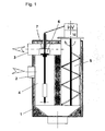
- Fig. 1 shows a schematic view of the electrostatic precipitator with a suitable arrangement of the clean gas pipe.
- the electrostatic precipitator comprises a separator housing 1 with a laterally arranged inlet opening 2 for the flue gas and a likewise laterally arranged opening for the outlet of the clean gas 3 .
- the separator housing 1 comprises an ionization stage 4 and a collector stage 5.
- a high-voltage insulator 6 is arranged below a cover cap 7 and above the inlet opening 2 .
- the flue gas flows at a temperature T1 in through the inlet opening 2 into the ionization stage 4 and the particles contained in the flue gas are electrically charged. Subsequently, the particles on the surrounding surfaces and in the Collector stage 5 deposited.
- the gas cleaned of particles passes through the opening for the clean gas outlet 3, which surrounds the covering cap 7 , at a temperature T2.
- T2 has a value less than T1.
- T1 and T2 are much higher than the ambient temperature, whereby the temperature gradient between the flue gas and the high-voltage insulator 6 is substantially reduced.
Description
Die Erfindung betrifft einen elektrostatischen Abscheider zur Partikelabscheidung, wie sie zum Beispiel in Verbrennungskammern, Holzöfen oder anderen Holzverbrennungsanlagen anfallen.The invention relates to an electrostatic precipitator for particle separation, as obtained for example in combustion chambers, wood stoves or other wood burning plants.
Elektrostatische Abscheider werden ganz allgemein zur Reinigung von Rauchgas durch Partikelabscheidung eingesetzt. Das zu reinigende Rauchgas wird in den elektrostatischen Abscheider eingeleitet, der eine Ionisierungsstufe, zur elektrischen Ladung der Partikel, und eine Kollektorstufe, zum Abscheiden der geladenen Partikel, umfasst. In der Ionisierungsstufe strömt das zu reinigende Gas durch das elektrische Feld zwischen einer Hochspannungselektrode und einer auf einem Bezugspotential, meist Erdpotential, liegenden Elektrode, in dem die im Rauchgas enthaltenen Partikel über Koronaentladung an der Hochspannungselektrode elektrisch geladen werden. Beim anschließenden Durchströmen der Kollektorstufe werden die Partikel dort auf der auf Bezugspotential liegenden Oberfläche abgeschieden und elektrisch neutralisiert.Electrostatic separators are generally used for cleaning flue gas by particle separation. The flue gas to be purified is introduced into the electrostatic precipitator, which comprises an ionization stage for the electric charge of the particles, and a collector stage for the separation of the charged particles. In the ionization stage, the gas to be purified flows through the electric field between a high voltage electrode and an electrode lying at a reference potential, usually ground potential, in which the particles contained in the flue gas are electrically charged via corona discharge at the high voltage electrode. During the subsequent passage through the collector stage, the particles are deposited there on the surface lying at reference potential and electrically neutralized.
Der Mechanismus der Abscheidung über Raumladung ist aus: "
Ein Nachteil der bekannten elektrostatischen Abscheideanlagen ist die Verschmutzung des Hochspannungsisolators, der in die vom Gas durchströmte Kammer hineinragt mit Partikeln aus z.B. Flugasche oder Ruß die in dem zu reinigenden Rauchgas enthalten sind. Aus dem allgemeinen Stand der Technik ist bekannt, dass ein steiler Temperaturgradient zwischen dem einströmenden Rauchgas und dem Isolator zu Verwirbelungen führt, die eine vermehrte Anlagerung von Ruß- und Aschepartikeln an dem Isolator zur Folge haben. Dadurch kommt es zu Spannungsüberschlägen, die die Effizienz des elektrostatischen Abscheiders verringern.A disadvantage of the known electrostatic precipitation systems is the contamination of the high-voltage insulator, which protrudes into the chamber through which gas flows with particles of, for example, fly ash or soot which are contained in the flue gas to be cleaned are. It is known from the general state of the art that a steep temperature gradient between the incoming flue gas and the insulator leads to turbulences, which result in an increased accumulation of soot and ash particles on the insulator. This leads to flashovers that reduce the efficiency of the electrostatic precipitator.
In diesem Zusammenhang sind dem allgemeinen Stand der Technik Lösungen zu entnehmen, die auf den Schutz und der Beheizung des Isolators beruhen. So offenbart die
Das Beheizen des Isolators erhöht jedoch den Energiebedarf des elektrostatischen Abscheiders insgesamt und zusätzliche Heizelemente erhöhen den Konstruktionsaufwand.However, heating the insulator increases the overall energy consumption of the electrostatic precipitator and additional heating elements increase the design effort.
Ausgehend davon ist die Aufgabe der Erfindung die genannten Nachteile zu vermeiden und einen elektrostatischen Abscheider anzugeben, der eine effiziente Rauchgasreinigung bei verlängerter Betriebsdauer sichert. Insbesondere soll die Verschmutzung des Hochspannungsisolators durch Ruß- und Aschepartikel vermieden werden.Based on this, the object of the invention to avoid the disadvantages mentioned and to provide an electrostatic precipitator, which ensures efficient flue gas cleaning at extended operating time. In particular, the contamination of the high-voltage insulator should be avoided by soot and ash particles.
Gelöst wird diese Aufgabe durch eine Vorrichtung mit den Merkmalen nach Anspruch 1.This object is achieved by a device having the features of claim 1.
Zur Lösung der Aufgabe wird ein elektrostatischer Abscheider vorgeschlagen, bei dem der Hochspannungsisolator mit einer Abdeckkappe umgeben ist, wobei diese Abdeckkappe in das Reingasrohr hineinragt und von dem von Partikeln gereinigte Gas umströmt wird.To solve the problem, an electrostatic precipitator is proposed, in which the high-voltage insulator is surrounded by a cap, said cap projecting into the clean gas pipe and is surrounded by the cleaned of particles of gas.
Das zu reinigende Rauchgas strömt mit einer ersten Temperatur (T1) in die Ionisierungsstufe des elektrostatischen Abscheiders. Dort werden die sich in dem Rauchgas befindlichen Partikel elektrisch geladen und scheiden sich auf den umliegenden, auf einem Bezugspotential liegenden Oberflächen ab. Das von Partikeln gereinigte Rauchgas tritt danach durch den Reingasaustritt mit einer zweiten Temperatur (T2) in das Reingasrohr. Diese zweite Temperatur weist einen Wert auf, der unterhalb der ersten Temperatur T1 liegt, jedoch weit oberhalb der Umgebungstemperatur. Durch die erfindungsgemäße Anordnung des Reingasrohres, wird demnach die Abdeckkappe des Hochspannungsisolators von dem Reingas umströmt und erwärmt. Durch Wärmeübertragung wird der von der Abdeckkappe umgebende Isolator erwärmt. Der Temperaturgradient zwischen dem partikelgeladenen Rauchgas und dem Hochspannungsisolator wird auf diese Weise verringert.The flue gas to be cleaned flows at a first temperature (T1) into the ionization stage of the electrostatic precipitator. There, the particles located in the flue gas are electrically charged and deposit on the surrounding surfaces lying on a reference potential. The cleaned of particles flue gas then passes through the clean gas outlet at a second temperature (T2) in the clean gas pipe. This second temperature has a value which is below the first temperature T1, but far above the ambient temperature. The inventive arrangement of the clean gas pipe, therefore, the cap of the high-voltage insulator is flowed around by the clean gas and heated. By heat transfer the surrounding of the cap insulator is heated. The temperature gradient between the particle-laden flue gas and the high-voltage insulator is reduced in this way.
Die Erfindung wird mit einem Ausführungsbeispiel anhand der
Der elektrostatische Abscheider umfasst ein Abscheidergehäuse 1 mit einer seitlich angeordneten Einlassöffnung 2 für das Rauchgas und einer ebenfalls seitlich angeordneten Öffnung für den Austritt des Reingases 3. Das Abscheidergehäuse 1 umfasst eine Ionisierungsstufe 4 und eine Kollektorstufe 5. Ein Hochspannungsisolator 6 ist unterhalb einer Abdeckkappe 7 und oberhalb der Einlassöffnung 2 angeordnet.The electrostatic precipitator comprises a separator housing 1 with a laterally arranged
Das Rauchgas strömt mit einer Temperatur T1 in durch die Einlassöffnung 2 in die Ionisierungsstufe 4 und die im Rauchgas enthaltenen Partikel werden elektrisch geladen. Nachfolgend werden die Partikel an den umgebenden Oberflächen und in der Kollektorstufe 5 abgeschieden. Das von Partikeln gereinigte Gas tritt mit einer Temperatur T2 durch die Öffnung für den Reingasaustritt 3, welcher die Abdeckkappe 7 umgibt. Durch Wärmeleitung und Wärmeübertragung, wird der Hochspannungsisolator 6 auf die Temperatur T2 erwärmt, wobei T2 einen geringeren Wert als T1 hat. T1 und T2 sind jedoch wesentlich höher als die Um-gebungstemperatur, wodurch sich der Temperaturgradient zwischen dem Rauchgas und dem Hochspannungsisolator 6 wesentlich verringert.The flue gas flows at a temperature T1 in through the inlet opening 2 into the
- 11
- Abscheidergehäuseseparator
- 22
- Einlassöffnung für RauchgaseintrittInlet opening for flue gas inlet
- 33
- Öffnung für ReingasautrittOpening for clean gas ride
- 44
- Ionisierungsstufeionization
- 55
- Kollektorstufecollector stage
- 66
- HochspannungsisolatorHigh-voltage insulator
- 77
- Abdeckkappecap
Claims (1)
- Electrostatic separator for the purification of particle-laden waste gas, comprising:a) a waste gas inlet (2)b) means for the electrical charging of particles with a high-voltage connectionc) separation surfaces with a reference potential for the potential of the high-voltage connection for the electrically charged particlesd) a high-voltage isolator (6) between high-voltage connection and separator surfacese) a collector step with purified gas outlet (3, 5)characterised in that
the high-voltage isolator (6) is surrounded by a gas-tight cover cap (7), which projects into a pipe which is connected to the purified gas outlet (3).
Applications Claiming Priority (1)
| Application Number | Priority Date | Filing Date | Title |
|---|---|---|---|
| DE200910030804 DE102009030804B4 (en) | 2009-06-27 | 2009-06-27 | Electrostatic separator for particle separation |
Publications (2)
| Publication Number | Publication Date |
|---|---|
| EP2266703A1 EP2266703A1 (en) | 2010-12-29 |
| EP2266703B1 true EP2266703B1 (en) | 2015-11-04 |
Family
ID=42668897
Family Applications (1)
| Application Number | Title | Priority Date | Filing Date |
|---|---|---|---|
| EP10003842.1A Not-in-force EP2266703B1 (en) | 2009-06-27 | 2010-04-10 | Electrostatic separator for particle separation |
Country Status (2)
| Country | Link |
|---|---|
| EP (1) | EP2266703B1 (en) |
| DE (1) | DE102009030804B4 (en) |
Families Citing this family (1)
| Publication number | Priority date | Publication date | Assignee | Title |
|---|---|---|---|---|
| CN108722671A (en) * | 2018-07-12 | 2018-11-02 | 佛山市博顿空气科技有限公司 | A kind of workshop inorganization flue gas purifying equipment |
Family Cites Families (11)
| Publication number | Priority date | Publication date | Assignee | Title |
|---|---|---|---|---|
| FR550371A (en) * | 1921-08-27 | 1923-03-05 | Acieries Et Forges Firminy | Protection of high voltage insulators against humidity and dust in electrical gas cleaning |
| FR550372A (en) * | 1921-08-27 | 1923-03-05 | Acieries Et Forges Firminy | Device to prevent any swaying of the tensor weights of the axial wires (or of the axial electrodes), and to ensure the perfect centering of these wires in the tubes, in devices for the electrical purification of gases |
| DE1093447B (en) * | 1959-07-28 | 1960-11-24 | Metallgesellschaft Ag | Device for preventing the formation of eddies leading to pollution during the ventilation of insulators in electrical gas cleaning or emulsion separation systems |
| US4314885A (en) | 1978-10-18 | 1982-02-09 | The Babcock & Wilcox Company | Industrial technique |
| GB2046132B (en) * | 1979-04-02 | 1983-02-09 | Environmental Elements Corp | Protector tube for high voltage suspension insulator of an electro-static precipitator |
| DE3902812C1 (en) * | 1988-03-30 | 1990-01-04 | Johannes A. 7980 Ravensburg De Mueller | Electrostatic precipitator for the removal of particulates from the exhaust of internal-combustion devices or internal combustion engines and the catalytically initiated combustion of said particulates by means of an electric heating device |
| DE9115279U1 (en) | 1990-12-12 | 1992-02-20 | Noell-Krc Umwelttechnik Gmbh, 8700 Wuerzburg, De | |
| FR2798303B1 (en) * | 1999-09-14 | 2001-11-09 | Daniel Teboul | DEVICE FOR TREATING A GASEOUS MEDIUM, IN PARTICULAR EXHAUST GASES FROM AN INTERNAL COMBUSTION ENGINE, AND VEHICLE EQUIPPED WITH SUCH A DEVICE |
| US6508861B1 (en) * | 2001-10-26 | 2003-01-21 | Croll Reynolds Clean Air Technologies, Inc. | Integrated single-pass dual-field electrostatic precipitator and method |
| US6902604B2 (en) * | 2003-05-15 | 2005-06-07 | Fleetguard, Inc. | Electrostatic precipitator with internal power supply |
| DE102008011949A1 (en) | 2008-02-29 | 2010-01-21 | Forschungszentrum Karlsruhe Gmbh | Electrostatic separator |
-
2009
- 2009-06-27 DE DE200910030804 patent/DE102009030804B4/en not_active Expired - Fee Related
-
2010
- 2010-04-10 EP EP10003842.1A patent/EP2266703B1/en not_active Not-in-force
Also Published As
| Publication number | Publication date |
|---|---|
| DE102009030804A1 (en) | 2011-01-13 |
| DE102009030804B4 (en) | 2011-07-28 |
| EP2266703A1 (en) | 2010-12-29 |
Similar Documents
| Publication | Publication Date | Title |
|---|---|---|
| US20140020558A1 (en) | Apparatus and method for removal of particulate matter from a gas | |
| CN104271248B (en) | Electric dust collector | |
| EP2892653B1 (en) | Method for collecting fine particles from flue gases, and a corresponding device and arrangement | |
| DE102007010973B4 (en) | Electrostatic precipitator for a small combustion plant | |
| EP2926909B1 (en) | Boiler | |
| US20160144380A1 (en) | Composite dust collector | |
| CN104841556A (en) | Low-low-temperature electric dust remover | |
| DE102008049211B4 (en) | Electrostatic separator for the purification of flue gases | |
| EP3705185A1 (en) | Electrostatic precipitator for the purification of flue gases | |
| EP2266703B1 (en) | Electrostatic separator for particle separation | |
| AT504902B1 (en) | ELECTRIC FILTER FOR A FIRING SYSTEM | |
| EP1361927A1 (en) | Electrostatic dust separator with integrated filter tubing | |
| EP2266702B1 (en) | Electrostatic separator for cleaning waste gas with an electrical restriction field | |
| EP2875854B1 (en) | Flue gas purification system for elimination of noxious substances from flue gas | |
| EP2251088B1 (en) | Electrostatic separator and heating system | |
| WO2022069586A1 (en) | Electrostatic separator, tube section and system producing particulate matter | |
| AT504749A2 (en) | ELECTROSTATIC FINE-AIR FILTER FOR SMOKE GAS CLEANING | |
| RU2353420C1 (en) | Electro-filter | |
| CN220371277U (en) | Cooking robot oil smoke separator | |
| CN205731622U (en) | A kind of laptop radiating air inlet filtering dust and ionic dust control unit | |
| WO2012048794A1 (en) | Collector stage of an electrostatic precipitator for cleaning flue gas produced during combustion processes | |
| AT515739B1 (en) | Electrostatic particle separator | |
| DE10018851A1 (en) | Device for separation of particles from exhaust gas of internal combustion engine has casing in which are located ionizer for electrical charging of exhaust gas particles and one or more collectors for accumulation of charged particles | |
| US20190270094A1 (en) | Boiler | |
| Chandra | Investigations on electrostatic precipitator: a case study |
Legal Events
| Date | Code | Title | Description |
|---|---|---|---|
| PUAI | Public reference made under article 153(3) epc to a published international application that has entered the european phase |
Free format text: ORIGINAL CODE: 0009012 |
|
| AK | Designated contracting states |
Kind code of ref document: A1 Designated state(s): AT BE BG CH CY CZ DE DK EE ES FI FR GB GR HR HU IE IS IT LI LT LU LV MC MK MT NL NO PL PT RO SE SI SK SM TR |
|
| AX | Request for extension of the european patent |
Extension state: AL BA ME RS |
|
| 17P | Request for examination filed |
Effective date: 20110128 |
|
| 17Q | First examination report despatched |
Effective date: 20131022 |
|
| GRAP | Despatch of communication of intention to grant a patent |
Free format text: ORIGINAL CODE: EPIDOSNIGR1 |
|
| INTG | Intention to grant announced |
Effective date: 20150529 |
|
| GRAS | Grant fee paid |
Free format text: ORIGINAL CODE: EPIDOSNIGR3 |
|
| GRAA | (expected) grant |
Free format text: ORIGINAL CODE: 0009210 |
|
| AK | Designated contracting states |
Kind code of ref document: B1 Designated state(s): AT BE BG CH CY CZ DE DK EE ES FI FR GB GR HR HU IE IS IT LI LT LU LV MC MK MT NL NO PL PT RO SE SI SK SM TR |
|
| REG | Reference to a national code |
Ref country code: GB Ref legal event code: FG4D Free format text: NOT ENGLISH |
|
| REG | Reference to a national code |
Ref country code: CH Ref legal event code: EP Ref country code: CH Ref legal event code: NV Representative=s name: ROTTMANN, ZIMMERMANN + PARTNER AG, CH |
|
| REG | Reference to a national code |
Ref country code: AT Ref legal event code: REF Ref document number: 758829 Country of ref document: AT Kind code of ref document: T Effective date: 20151115 |
|
| REG | Reference to a national code |
Ref country code: IE Ref legal event code: FG4D Free format text: LANGUAGE OF EP DOCUMENT: GERMAN |
|
| REG | Reference to a national code |
Ref country code: DE Ref legal event code: R096 Ref document number: 502010010568 Country of ref document: DE |
|
| REG | Reference to a national code |
Ref country code: NL Ref legal event code: MP Effective date: 20151104 |
|
| REG | Reference to a national code |
Ref country code: LT Ref legal event code: MG4D |
|
| REG | Reference to a national code |
Ref country code: FR Ref legal event code: PLFP Year of fee payment: 7 |
|
| PG25 | Lapsed in a contracting state [announced via postgrant information from national office to epo] |
Ref country code: ES Free format text: LAPSE BECAUSE OF FAILURE TO SUBMIT A TRANSLATION OF THE DESCRIPTION OR TO PAY THE FEE WITHIN THE PRESCRIBED TIME-LIMIT Effective date: 20151104 Ref country code: LT Free format text: LAPSE BECAUSE OF FAILURE TO SUBMIT A TRANSLATION OF THE DESCRIPTION OR TO PAY THE FEE WITHIN THE PRESCRIBED TIME-LIMIT Effective date: 20151104 Ref country code: NO Free format text: LAPSE BECAUSE OF FAILURE TO SUBMIT A TRANSLATION OF THE DESCRIPTION OR TO PAY THE FEE WITHIN THE PRESCRIBED TIME-LIMIT Effective date: 20160204 Ref country code: IS Free format text: LAPSE BECAUSE OF FAILURE TO SUBMIT A TRANSLATION OF THE DESCRIPTION OR TO PAY THE FEE WITHIN THE PRESCRIBED TIME-LIMIT Effective date: 20160304 Ref country code: NL Free format text: LAPSE BECAUSE OF FAILURE TO SUBMIT A TRANSLATION OF THE DESCRIPTION OR TO PAY THE FEE WITHIN THE PRESCRIBED TIME-LIMIT Effective date: 20151104 Ref country code: HR Free format text: LAPSE BECAUSE OF FAILURE TO SUBMIT A TRANSLATION OF THE DESCRIPTION OR TO PAY THE FEE WITHIN THE PRESCRIBED TIME-LIMIT Effective date: 20151104 |
|
| PG25 | Lapsed in a contracting state [announced via postgrant information from national office to epo] |
Ref country code: PL Free format text: LAPSE BECAUSE OF FAILURE TO SUBMIT A TRANSLATION OF THE DESCRIPTION OR TO PAY THE FEE WITHIN THE PRESCRIBED TIME-LIMIT Effective date: 20151104 Ref country code: SE Free format text: LAPSE BECAUSE OF FAILURE TO SUBMIT A TRANSLATION OF THE DESCRIPTION OR TO PAY THE FEE WITHIN THE PRESCRIBED TIME-LIMIT Effective date: 20151104 Ref country code: FI Free format text: LAPSE BECAUSE OF FAILURE TO SUBMIT A TRANSLATION OF THE DESCRIPTION OR TO PAY THE FEE WITHIN THE PRESCRIBED TIME-LIMIT Effective date: 20151104 Ref country code: GR Free format text: LAPSE BECAUSE OF FAILURE TO SUBMIT A TRANSLATION OF THE DESCRIPTION OR TO PAY THE FEE WITHIN THE PRESCRIBED TIME-LIMIT Effective date: 20160205 Ref country code: PT Free format text: LAPSE BECAUSE OF FAILURE TO SUBMIT A TRANSLATION OF THE DESCRIPTION OR TO PAY THE FEE WITHIN THE PRESCRIBED TIME-LIMIT Effective date: 20160304 Ref country code: LV Free format text: LAPSE BECAUSE OF FAILURE TO SUBMIT A TRANSLATION OF THE DESCRIPTION OR TO PAY THE FEE WITHIN THE PRESCRIBED TIME-LIMIT Effective date: 20151104 |
|
| PG25 | Lapsed in a contracting state [announced via postgrant information from national office to epo] |
Ref country code: CZ Free format text: LAPSE BECAUSE OF FAILURE TO SUBMIT A TRANSLATION OF THE DESCRIPTION OR TO PAY THE FEE WITHIN THE PRESCRIBED TIME-LIMIT Effective date: 20151104 |
|
| REG | Reference to a national code |
Ref country code: DE Ref legal event code: R097 Ref document number: 502010010568 Country of ref document: DE |
|
| PG25 | Lapsed in a contracting state [announced via postgrant information from national office to epo] |
Ref country code: SK Free format text: LAPSE BECAUSE OF FAILURE TO SUBMIT A TRANSLATION OF THE DESCRIPTION OR TO PAY THE FEE WITHIN THE PRESCRIBED TIME-LIMIT Effective date: 20151104 Ref country code: DK Free format text: LAPSE BECAUSE OF FAILURE TO SUBMIT A TRANSLATION OF THE DESCRIPTION OR TO PAY THE FEE WITHIN THE PRESCRIBED TIME-LIMIT Effective date: 20151104 Ref country code: EE Free format text: LAPSE BECAUSE OF FAILURE TO SUBMIT A TRANSLATION OF THE DESCRIPTION OR TO PAY THE FEE WITHIN THE PRESCRIBED TIME-LIMIT Effective date: 20151104 Ref country code: RO Free format text: LAPSE BECAUSE OF FAILURE TO SUBMIT A TRANSLATION OF THE DESCRIPTION OR TO PAY THE FEE WITHIN THE PRESCRIBED TIME-LIMIT Effective date: 20151104 Ref country code: SM Free format text: LAPSE BECAUSE OF FAILURE TO SUBMIT A TRANSLATION OF THE DESCRIPTION OR TO PAY THE FEE WITHIN THE PRESCRIBED TIME-LIMIT Effective date: 20151104 Ref country code: BE Free format text: LAPSE BECAUSE OF NON-PAYMENT OF DUE FEES Effective date: 20160430 |
|
| PLBE | No opposition filed within time limit |
Free format text: ORIGINAL CODE: 0009261 |
|
| STAA | Information on the status of an ep patent application or granted ep patent |
Free format text: STATUS: NO OPPOSITION FILED WITHIN TIME LIMIT |
|
| 26N | No opposition filed |
Effective date: 20160805 |
|
| REG | Reference to a national code |
Ref country code: CH Ref legal event code: PCAR Free format text: NEW ADDRESS: GARTENSTRASSE 28 A, 5400 BADEN (CH) |
|
| PG25 | Lapsed in a contracting state [announced via postgrant information from national office to epo] |
Ref country code: SI Free format text: LAPSE BECAUSE OF FAILURE TO SUBMIT A TRANSLATION OF THE DESCRIPTION OR TO PAY THE FEE WITHIN THE PRESCRIBED TIME-LIMIT Effective date: 20151104 |
|
| GBPC | Gb: european patent ceased through non-payment of renewal fee |
Effective date: 20160410 |
|
| PG25 | Lapsed in a contracting state [announced via postgrant information from national office to epo] |
Ref country code: LU Free format text: LAPSE BECAUSE OF FAILURE TO SUBMIT A TRANSLATION OF THE DESCRIPTION OR TO PAY THE FEE WITHIN THE PRESCRIBED TIME-LIMIT Effective date: 20160410 |
|
| REG | Reference to a national code |
Ref country code: IE Ref legal event code: MM4A |
|
| PG25 | Lapsed in a contracting state [announced via postgrant information from national office to epo] |
Ref country code: GB Free format text: LAPSE BECAUSE OF NON-PAYMENT OF DUE FEES Effective date: 20160410 |
|
| REG | Reference to a national code |
Ref country code: FR Ref legal event code: PLFP Year of fee payment: 8 |
|
| PG25 | Lapsed in a contracting state [announced via postgrant information from national office to epo] |
Ref country code: IE Free format text: LAPSE BECAUSE OF NON-PAYMENT OF DUE FEES Effective date: 20160410 |
|
| REG | Reference to a national code |
Ref country code: FR Ref legal event code: PLFP Year of fee payment: 9 |
|
| PG25 | Lapsed in a contracting state [announced via postgrant information from national office to epo] |
Ref country code: HU Free format text: LAPSE BECAUSE OF FAILURE TO SUBMIT A TRANSLATION OF THE DESCRIPTION OR TO PAY THE FEE WITHIN THE PRESCRIBED TIME-LIMIT; INVALID AB INITIO Effective date: 20100410 Ref country code: CY Free format text: LAPSE BECAUSE OF FAILURE TO SUBMIT A TRANSLATION OF THE DESCRIPTION OR TO PAY THE FEE WITHIN THE PRESCRIBED TIME-LIMIT Effective date: 20151104 |
|
| PG25 | Lapsed in a contracting state [announced via postgrant information from national office to epo] |
Ref country code: MC Free format text: LAPSE BECAUSE OF FAILURE TO SUBMIT A TRANSLATION OF THE DESCRIPTION OR TO PAY THE FEE WITHIN THE PRESCRIBED TIME-LIMIT Effective date: 20151104 Ref country code: MK Free format text: LAPSE BECAUSE OF FAILURE TO SUBMIT A TRANSLATION OF THE DESCRIPTION OR TO PAY THE FEE WITHIN THE PRESCRIBED TIME-LIMIT Effective date: 20151104 Ref country code: TR Free format text: LAPSE BECAUSE OF FAILURE TO SUBMIT A TRANSLATION OF THE DESCRIPTION OR TO PAY THE FEE WITHIN THE PRESCRIBED TIME-LIMIT Effective date: 20151104 Ref country code: MT Free format text: LAPSE BECAUSE OF FAILURE TO SUBMIT A TRANSLATION OF THE DESCRIPTION OR TO PAY THE FEE WITHIN THE PRESCRIBED TIME-LIMIT Effective date: 20151104 |
|
| PG25 | Lapsed in a contracting state [announced via postgrant information from national office to epo] |
Ref country code: BG Free format text: LAPSE BECAUSE OF FAILURE TO SUBMIT A TRANSLATION OF THE DESCRIPTION OR TO PAY THE FEE WITHIN THE PRESCRIBED TIME-LIMIT Effective date: 20151104 |
|
| PGFP | Annual fee paid to national office [announced via postgrant information from national office to epo] |
Ref country code: CH Payment date: 20180424 Year of fee payment: 9 |
|
| PGFP | Annual fee paid to national office [announced via postgrant information from national office to epo] |
Ref country code: IT Payment date: 20180420 Year of fee payment: 9 Ref country code: FR Payment date: 20180424 Year of fee payment: 9 Ref country code: AT Payment date: 20180418 Year of fee payment: 9 |
|
| PGFP | Annual fee paid to national office [announced via postgrant information from national office to epo] |
Ref country code: DE Payment date: 20190418 Year of fee payment: 10 |
|
| REG | Reference to a national code |
Ref country code: CH Ref legal event code: PL |
|
| REG | Reference to a national code |
Ref country code: AT Ref legal event code: MM01 Ref document number: 758829 Country of ref document: AT Kind code of ref document: T Effective date: 20190410 |
|
| PG25 | Lapsed in a contracting state [announced via postgrant information from national office to epo] |
Ref country code: AT Free format text: LAPSE BECAUSE OF NON-PAYMENT OF DUE FEES Effective date: 20190410 Ref country code: CH Free format text: LAPSE BECAUSE OF NON-PAYMENT OF DUE FEES Effective date: 20190430 Ref country code: LI Free format text: LAPSE BECAUSE OF NON-PAYMENT OF DUE FEES Effective date: 20190430 |
|
| PG25 | Lapsed in a contracting state [announced via postgrant information from national office to epo] |
Ref country code: FR Free format text: LAPSE BECAUSE OF NON-PAYMENT OF DUE FEES Effective date: 20190430 |
|
| PG25 | Lapsed in a contracting state [announced via postgrant information from national office to epo] |
Ref country code: IT Free format text: LAPSE BECAUSE OF NON-PAYMENT OF DUE FEES Effective date: 20190410 |
|
| REG | Reference to a national code |
Ref country code: DE Ref legal event code: R119 Ref document number: 502010010568 Country of ref document: DE |
|
| PG25 | Lapsed in a contracting state [announced via postgrant information from national office to epo] |
Ref country code: DE Free format text: LAPSE BECAUSE OF NON-PAYMENT OF DUE FEES Effective date: 20201103 |