EP2265484B1 - Einsatz mit integriertem befestigungselement - Google Patents
Einsatz mit integriertem befestigungselement Download PDFInfo
- Publication number
- EP2265484B1 EP2265484B1 EP09721697.2A EP09721697A EP2265484B1 EP 2265484 B1 EP2265484 B1 EP 2265484B1 EP 09721697 A EP09721697 A EP 09721697A EP 2265484 B1 EP2265484 B1 EP 2265484B1
- Authority
- EP
- European Patent Office
- Prior art keywords
- insert
- carrier
- attachment
- peripheral edge
- cavity
- Prior art date
- Legal status (The legal status is an assumption and is not a legal conclusion. Google has not performed a legal analysis and makes no representation as to the accuracy of the status listed.)
- Not-in-force
Links
- 239000000463 material Substances 0.000 claims description 57
- 230000002093 peripheral effect Effects 0.000 claims description 41
- 238000000034 method Methods 0.000 claims description 14
- 239000000969 carrier Substances 0.000 claims description 9
- 238000010438 heat treatment Methods 0.000 claims description 6
- 238000012876 topography Methods 0.000 claims description 6
- 238000009434 installation Methods 0.000 claims description 5
- 239000004033 plastic Substances 0.000 claims description 5
- 229920003023 plastic Polymers 0.000 claims description 5
- 230000004048 modification Effects 0.000 claims description 4
- 238000012986 modification Methods 0.000 claims description 4
- 230000003014 reinforcing effect Effects 0.000 claims description 4
- 229910052751 metal Inorganic materials 0.000 description 7
- 239000002184 metal Substances 0.000 description 7
- 230000002787 reinforcement Effects 0.000 description 6
- 238000007789 sealing Methods 0.000 description 6
- 239000012876 carrier material Substances 0.000 description 4
- 229910000831 Steel Inorganic materials 0.000 description 3
- 229920001971 elastomer Polymers 0.000 description 3
- 239000000945 filler Substances 0.000 description 3
- 239000006260 foam Substances 0.000 description 3
- 238000003780 insertion Methods 0.000 description 3
- 230000037431 insertion Effects 0.000 description 3
- 229920000642 polymer Polymers 0.000 description 3
- 239000010959 steel Substances 0.000 description 3
- BAPJBEWLBFYGME-UHFFFAOYSA-N Methyl acrylate Chemical compound COC(=O)C=C BAPJBEWLBFYGME-UHFFFAOYSA-N 0.000 description 2
- 239000004677 Nylon Substances 0.000 description 2
- 229920001577 copolymer Polymers 0.000 description 2
- 239000000806 elastomer Substances 0.000 description 2
- 239000005038 ethylene vinyl acetate Substances 0.000 description 2
- 239000002657 fibrous material Substances 0.000 description 2
- 239000010410 layer Substances 0.000 description 2
- 229920001778 nylon Polymers 0.000 description 2
- 229920001200 poly(ethylene-vinyl acetate) Polymers 0.000 description 2
- 229920001897 terpolymer Polymers 0.000 description 2
- 229920001169 thermoplastic Polymers 0.000 description 2
- 239000004416 thermosoftening plastic Substances 0.000 description 2
- 239000002699 waste material Substances 0.000 description 2
- 241000191291 Abies alba Species 0.000 description 1
- QTBSBXVTEAMEQO-UHFFFAOYSA-M Acetate Chemical compound CC([O-])=O QTBSBXVTEAMEQO-UHFFFAOYSA-M 0.000 description 1
- NIXOWILDQLNWCW-UHFFFAOYSA-M Acrylate Chemical compound [O-]C(=O)C=C NIXOWILDQLNWCW-UHFFFAOYSA-M 0.000 description 1
- 239000004412 Bulk moulding compound Substances 0.000 description 1
- 229910000975 Carbon steel Inorganic materials 0.000 description 1
- 239000004593 Epoxy Substances 0.000 description 1
- FYYHWMGAXLPEAU-UHFFFAOYSA-N Magnesium Chemical compound [Mg] FYYHWMGAXLPEAU-UHFFFAOYSA-N 0.000 description 1
- CERQOIWHTDAKMF-UHFFFAOYSA-M Methacrylate Chemical compound CC(=C)C([O-])=O CERQOIWHTDAKMF-UHFFFAOYSA-M 0.000 description 1
- 239000004721 Polyphenylene oxide Substances 0.000 description 1
- 239000003677 Sheet moulding compound Substances 0.000 description 1
- RTAQQCXQSZGOHL-UHFFFAOYSA-N Titanium Chemical compound [Ti] RTAQQCXQSZGOHL-UHFFFAOYSA-N 0.000 description 1
- 230000004913 activation Effects 0.000 description 1
- 239000012790 adhesive layer Substances 0.000 description 1
- 229910052782 aluminium Inorganic materials 0.000 description 1
- XAGFODPZIPBFFR-UHFFFAOYSA-N aluminium Chemical compound [Al] XAGFODPZIPBFFR-UHFFFAOYSA-N 0.000 description 1
- 239000011324 bead Substances 0.000 description 1
- 238000005452 bending Methods 0.000 description 1
- DQXBYHZEEUGOBF-UHFFFAOYSA-N but-3-enoic acid;ethene Chemical compound C=C.OC(=O)CC=C DQXBYHZEEUGOBF-UHFFFAOYSA-N 0.000 description 1
- CQEYYJKEWSMYFG-UHFFFAOYSA-N butyl acrylate Chemical compound CCCCOC(=O)C=C CQEYYJKEWSMYFG-UHFFFAOYSA-N 0.000 description 1
- 239000004927 clay Substances 0.000 description 1
- 238000000576 coating method Methods 0.000 description 1
- 238000005520 cutting process Methods 0.000 description 1
- 230000006378 damage Effects 0.000 description 1
- 230000003247 decreasing effect Effects 0.000 description 1
- 238000001035 drying Methods 0.000 description 1
- 230000000694 effects Effects 0.000 description 1
- 239000013536 elastomeric material Substances 0.000 description 1
- 239000003822 epoxy resin Substances 0.000 description 1
- 229920001038 ethylene copolymer Polymers 0.000 description 1
- 239000004744 fabric Substances 0.000 description 1
- 238000009472 formulation Methods 0.000 description 1
- 229910052749 magnesium Inorganic materials 0.000 description 1
- 239000011777 magnesium Substances 0.000 description 1
- 238000004519 manufacturing process Methods 0.000 description 1
- 239000000203 mixture Substances 0.000 description 1
- 239000000178 monomer Substances 0.000 description 1
- 239000002105 nanoparticle Substances 0.000 description 1
- 239000003973 paint Substances 0.000 description 1
- 238000010422 painting Methods 0.000 description 1
- 229920000647 polyepoxide Polymers 0.000 description 1
- 229920000570 polyether Polymers 0.000 description 1
- 230000037452 priming Effects 0.000 description 1
- 230000009257 reactivity Effects 0.000 description 1
- 150000003384 small molecules Chemical class 0.000 description 1
- 238000003860 storage Methods 0.000 description 1
- 239000004616 structural foam Substances 0.000 description 1
- 239000000126 substance Substances 0.000 description 1
- 239000012815 thermoplastic material Substances 0.000 description 1
- 239000010936 titanium Substances 0.000 description 1
- 229910052719 titanium Inorganic materials 0.000 description 1
- 239000004711 α-olefin Substances 0.000 description 1
Images



Classifications
-
- B—PERFORMING OPERATIONS; TRANSPORTING
- B62—LAND VEHICLES FOR TRAVELLING OTHERWISE THAN ON RAILS
- B62D—MOTOR VEHICLES; TRAILERS
- B62D29/00—Superstructures, understructures, or sub-units thereof, characterised by the material thereof
- B62D29/001—Superstructures, understructures, or sub-units thereof, characterised by the material thereof characterised by combining metal and synthetic material
- B62D29/004—Superstructures, understructures, or sub-units thereof, characterised by the material thereof characterised by combining metal and synthetic material the metal being over-moulded by the synthetic material, e.g. in a mould
-
- B—PERFORMING OPERATIONS; TRANSPORTING
- B62—LAND VEHICLES FOR TRAVELLING OTHERWISE THAN ON RAILS
- B62D—MOTOR VEHICLES; TRAILERS
- B62D29/00—Superstructures, understructures, or sub-units thereof, characterised by the material thereof
- B62D29/001—Superstructures, understructures, or sub-units thereof, characterised by the material thereof characterised by combining metal and synthetic material
- B62D29/002—Superstructures, understructures, or sub-units thereof, characterised by the material thereof characterised by combining metal and synthetic material a foamable synthetic material or metal being added in situ
-
- Y—GENERAL TAGGING OF NEW TECHNOLOGICAL DEVELOPMENTS; GENERAL TAGGING OF CROSS-SECTIONAL TECHNOLOGIES SPANNING OVER SEVERAL SECTIONS OF THE IPC; TECHNICAL SUBJECTS COVERED BY FORMER USPC CROSS-REFERENCE ART COLLECTIONS [XRACs] AND DIGESTS
- Y10—TECHNICAL SUBJECTS COVERED BY FORMER USPC
- Y10T—TECHNICAL SUBJECTS COVERED BY FORMER US CLASSIFICATION
- Y10T29/00—Metal working
- Y10T29/49—Method of mechanical manufacture
- Y10T29/49826—Assembling or joining
- Y10T29/49863—Assembling or joining with prestressing of part
- Y10T29/49865—Assembling or joining with prestressing of part by temperature differential [e.g., shrink fit]
-
- Y—GENERAL TAGGING OF NEW TECHNOLOGICAL DEVELOPMENTS; GENERAL TAGGING OF CROSS-SECTIONAL TECHNOLOGIES SPANNING OVER SEVERAL SECTIONS OF THE IPC; TECHNICAL SUBJECTS COVERED BY FORMER USPC CROSS-REFERENCE ART COLLECTIONS [XRACs] AND DIGESTS
- Y10—TECHNICAL SUBJECTS COVERED BY FORMER USPC
- Y10T—TECHNICAL SUBJECTS COVERED BY FORMER US CLASSIFICATION
- Y10T428/00—Stock material or miscellaneous articles
- Y10T428/24—Structurally defined web or sheet [e.g., overall dimension, etc.]
- Y10T428/24777—Edge feature
Definitions
- the present invention relates generally to a baffling, sealing or reinforcement member that includes a carrier with an integrated fastener.
- the present invention contemplates a method for locally reinforcing or baffling a structure having a hollow cavity, comprising the steps of: providing an insert including a generally flat carrier having a first face and an opposing second face each terminating at a peripheral edge, wherein the carrier includes a thermally expandable polymeric material on at least a portion of one of the first or second faces and includes at least one integrally formed attachment that projects outwardly from the peripheral edge; inserting the attachment through an aperture in a wall of the structure; at least partially rotating the integrally formed attachment, so that after such rotating the first face and the second face project generally transversely into the cavity and a gap is defined between the peripheral edge and the wall of the structure; heating the thermally expandable polymeric material to cause it to expand and seal the gap that exists between the peripheral edge and the wall of the structure; thereby separating the hollow cavity into separate chambers on either side of the insert.
- the generally flat carrier is constructed of metal, polymeric material, elastomeric material, fibrous material, thermoplastic material, plastics, nylon, or any combination thereof;
- the generally flat carrier is a metal sheet;
- the attachment includes at least two spaced apart projections; the attachment includes only one projection; the insert is held in place within the hollow cavity, prior to the heating step, solely by the attachment;
- the attachment includes a laterally projecting arm that has a free end; the free end projects transversely outward; the free end projects transversely inward, the carrier includes at least one cut-out through which a component passes in the resulting final structure;
- the at least partially rotating step includes a step of flexing the insert to a stress within its elastic limits and below its plastic yield stress, so that permanent deformation does not occur during installation;
- the at least partially rotating step includes a step of flexing the insert, so that permanent deformation occurs during installation;
- the insert includes two carriers, each of which is located within a separate cavity;
- the present invention contemplates a method for locally reinforcing or baffling a structure having a hollow cavity of a vehicle, comprising the steps of: providing an insert including a generally flat carrier having a first face and an opposing second face each terminating at a peripheral edge having at least one substantially straight edge portion, wherein the carrier: includes a thermally expandable polymeric material on at least a portion of one of the first or second faces; includes at least one integrally formed attachment that projects outwardly from the peripheral edge, wherein the attachment includes at least two spaced apart projections; and includes at least one integrated structure that locally modifies the surface topography structure of the carrier, imparts at least one local property or performance modification within the carrier, or both; inserting the attachment through an aperture in a wall of the structure; at least partially rotating the integrally formed attachment, so that after such rotating the first face and the second face project generally transversely into the cavity and a gap is defined between the peripheral edge and the wall of the structure; heating the thermally expandable polymeric material to cause it to expand
- the present invention contemplates an insert comprising a generally flat carrier having a first face and an opposing second face that each terminate at a peripheral edge, wherein the carrier includes: a thermally expandable polymeric material on at least a portion of one of the first or second faces; and includes at least one integrally formed attachment that projects outwardly from the peripheral edge.
- the carrier includes opposing substantially parallel faces that have a surface topography that varies along its length, the peripheral edge of the insert lies substantially in a common plane along the entirety of the part.
- the present invention provides an insert that includes a carrier, an expandable material (e.g., thermally expandable material) located on at least a portion of the carrier, and at least one integrally formed attachment (which may be generally coplanar with the carrier) that projects outwardly (e.g., laterally) from the carrier.
- the inserts of the present invention are preferably placed within a hollow cavity in a transverse direction so that once the insert is sealed into place via the thermally expandable material, the hollow cavity is separated into two separate chambers.
- the inserts of the present invention are inserted into a cavity within an automotive vehicle and more preferably the cavity is part of a vehicle frame.
- the inserts are preferably located within the cavity prior to painting and/or priming activities so that the heat of a paint bake oven cures the expandable material.
- Figs. 1A and 1B show one embodiment of the inserts of the present invention.
- the insert 5 is shown including a carrier 6 having a layer of thermally expandable material 32 placed thereon.
- the carrier includes two faces, a first face 27 and an opposing second face 28.
- the opposing faces of the carrier may include a surface topography that varies along the length of the carrier, or the surface topography may remain substantially consistent along the carrier.
- the carrier may be a sheet-like structure and include generally parallel opposing faces.
- the carrier as shown includes a peripheral edge portion 22 such that a section of the peripheral edge portion 22 is an arcuate edge portion 24 and a section of the peripheral edge portion 22 is a substantially straight edge portion 26.
- the peripheral edge portion preferably includes at least three continuously adjoining edge portions.
- the peripheral edge portion may include at least four or at least five or more continuously adjoining edge portions.
- the carrier 6 further includes an attachment 14, shown as two spaced apart projections that are integrally formed with the carrier.
- the attachment 14 projects from the substantially straight edge portion 26 of the peripheral edge.
- the attachment may be generally coplanar with the faces of the carrier.
- the attachment 14 includes one or more free ends 15 located at an end of a projection that is not in contact with the remainder of the insert.
- the free ends may extend transversely inward, or transversely outward.
- the free ends extend away from one another such that the only means by which the attachment may be inserted through an aperture is by flexing.
- the flexing acts to temporarily reduce the distance between the free ends during insertion, where after insertion the free ends return to the same or substantially the same position as prior to flexing.
- the spacing between the free ends is sufficient so that during flexing the free ends do not contact one another without permanent deformation of the insert or possible destruction of the carrier.
- the space between the free ends may be 1 cm, 2 cm, 5 cm, 10 cm or more.
- the insert may optionally include a cutout area 20 through which a vehicle component may be passed.
- the insert may include the expandable material covering only a portion of one or two of the faces of the carrier.
- the insert may include the expandable material covering substantially the entirety of one or more of the faces.
- the expandable material may cover only a portion of the one or more faces of the carrier.
- the thermally expandable material 32 may not extend beyond the peripheral edge portion 22 of the carrier. Alternatively, the thermally expandable material 32 may extend beyond the peripheral edge portion 22 in some areas of the carrier. Preferably, the thermally expandable material does not extend to cover any cutout portion.
- Fig. 1C depicts the insert of Figs. 1A and 1B when located within a hollow vehicle cavity 10.
- the cavity is defined by a cavity wall 12 containing one or more apertures 16.
- the one or more apertures 16 are located in areas along the cavity wall 12 that correspond with the location of the attachment 14 of the insert so that the attachment may be inserted through the one or more apertures 16.
- the one or more apertures may be generally rectangular, generally circular, or any appropriate shape that allows entry of the insert attachment.
- the attachment After insertion into the apertures, the attachment may have some rotational capability such that the insert is capable of rotating about the apertures. The amount of rotation may be 10°, 20°, 30°, or more.
- the insert is configured so that when it is flexed the free ends 15 of any attachment 14 will move to allow the free ends to pass through the apertures 16 in a structure, and upon release of the pressure of the flexing, the free ends 15 will optionally return to their original state from the elasticity of the material, such that the free ends form an interference fit that prevents removal of the free ends from the apertures.
- the intrinsic elasticity of the carrier may spring the flexed material toward its original configuration so that the attachments resist pull through from any aperture structures against which they are bearing.
- a gap 18 is formed between the peripheral edge portion 22 and the cavity 12.
- the presence of the gap 18 allows for coatings or other materials to pass through the gap prior to expansion of the expandable material.
- the gap 18 will be filled and sealed. In preferred embodiments, the sealing of the gap 18 will result in the cavity being separated into two distinct chambers.
- the insert may be shaped so that when placed within a cavity in a transverse position, the shape of the insert is similar to that of the cavity so that size of the gap between the peripheral edge portion and cavity wall is relatively consistent around the insert.
- the shape of the insert may be a generally triangular shape as shown in Figs. 1A-1C .
- the shape of the insert may also be substantially rectangular, substantially circular, or any combination of the foregoing shapes.
- the shape of the insert may be any shape so that shape of the insert corresponds with the shape of the cavity.
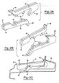
- Figs. 2A and 2B show an additional embodiment of the inserts of the present invention, such that the insert is made up of more than one carrier 6.
- the inserts shown include two carriers, each having a main body portion, a portion that extends in an upward direction (e.g., an inboard position) 42 and a portion that extends in the opposite direction (e.g., an outboard position) 44.
- the inserts both include an inboard position that is a different shape from the outboard position.
- the inboard position, the outboard position, or both include a bulbous portion.
- the two carriers each have an attachment including two spaced apart projections such that the projections extend away from the main body portion.
- the multiple carrier parts may be fabricated from a common sheet of material to help avoid waste.
- Fig. 2C illustrates the two carriers as inserted into a cavity 12.
- the cavity shown includes a dividing section 54 of the cavity wall 12 that divides the cavity wherein the dividing section of the cavity wall includes the apertures 16 for entry of the attachment 14 of the inserts.
- the two inserts are located on opposing sides of the dividing section 54 of the cavity wall 12. Once inserted, the attachment of each insert may contact the attachment of the other opposing insert as shown in Fig. 2C .
- Fig. 3B depicts a similar cavity as shown in Fig. 2C , including a dividing section 54 of the cavity wall 12.
- the insert includes cutout areas 70, 72 that correspond with the dividing section 54 of the cavity wall.
- the cutout areas 70, 72 create a first top portion 78 and a second or bottom portion 74 of the insert.
- the insert includes an attachment 14 shown as two projections, the top portion 78 and the bottom portion 74 each including one of the projections.
- Fig. 4A illustrates an additional embodiment of the insert, such that the insert includes an integrated structure 92.
- the integrated structure 92 is shown as a bend tab that may be substantially non-coplanar with the remainder of the insert.
- the integrated structure may include any structure that locally modifies the surface topography structure of the carrier or imparts at least one local property or performance modification within the carrier, or both. Examples of such integrated structures include, but are not limited to ribs, beads, dimples, bend tabs, notches or some other structure that includes a portion projecting away from the surface of the insert (e.g., so that the insert projects into each of the x, y and z planes of a Cartesian coordinate system).
- the integrated structure may be formed by subjecting the carrier to a secondary operation that deforms the carrier thereby forming the integrated structure.
- This secondary operation may be performed before or after any thermally expandable material is applied to the carrier. If the thermally expandable material is already applied to the carrier at the time of deformation, the thermally expandable material will undergo deformation as well, resulting in substantially the same sectional profile in both the carrier and expandable material. The resulting bend tab or other integrated structure will then project generally outward, such as in the longitudinal axis of the cavity.
- the insert is further shown as including an additional integrated structure formed as a notch. The notch may project inwardly from the peripheral edge of the carrier and adjoin the bend tab as shown.
- Fig. 4B shows a profile view of the insert depicting the decreasing thickness of the bend tab as the bend tab.
- the integrated structure may extend only partially across the carrier and be bounded on one of its ends by the peripheral edge.
- the integrated structure may extend only partially across the carrier and be bounded on neither of its ends by the peripheral edge.
- the integrated structure may extend entirely across the carrier and be bounded on both of its ends by the peripheral edge.
- the integrated structure may extend substantially entirely across the carrier and be bounded on at least one of its ends by the peripheral edge.
- the carrier including the integrated structure has substantially the same sectional thickness over its entire body.
- the carrier material is a flat metal sheet.
- the carrier material is a high strength to weight metal, such as aluminum, titanium, magnesium or any combination thereof. More preferably the metal is steel (e.g., a plain carbon steel).
- the carrier may also be made of a sheet molding compound or bulk molding compound such as that described in U.S. Patent No. 7,313,865 .
- the carrier and may also include a variety of other materials such as polymers, elastomers, fibrous materials (e.g., cloth or woven materials), thermoplastics, plastics, nylon, combinations thereof or the like.
- the carrier may be a polymeric sheet. Multiple carrier parts may be fabricated from a common sheet of material (e.g., shim steel), such as is shown in Figs. 2A and 3A , to help avoid waste.
- the thickness of the carrier for the inserts for any of the embodiments herein is from about 5.3 mm to about 0.30 mm (about 5 to about 30 gauge) (e.g., it is about 3.4 mm to about 0.53 mm (about 10 to about 25 gauge)).
- they may be formed of shim steel (e.g., having a thickness less than about 1 mm, and preferably greater than about 0.1 mm).
- One or more layers of expandable material may have a thickness of about 0.5 to about 6 mm, more preferably about 1 to about 3 mm.
- the thickness of the carrier is less than about 1 cm.
- Typical overall part thickness (including the expandable material) will be about 1 to about 6 mm, and more preferably about 3 to about 4 mm.
- the thermally expandable material may be generally dry to the touch or tacky and may be shaped in any form of desired pattern, placement, or thickness, but is preferably of substantially uniform thickness.
- a preferred heat activated material is an expandable polymer or plastic, and preferably one that is foamable.
- a particularly preferred material is a relatively high expansion foam having a polymeric formulation that includes one or more of an epoxy resin, an acetate (e.g.
- the foam may also be an EVA/rubber based material, including an ethylene copolymer or terpolymer that may possess an alpha-olefin.
- the polymer is composed of two or three different monomers, i.e., small molecules with high chemical reactivity that are capable of linking up with similar molecules.
- Preferred expandable materials include those available from L&L Products, Inc. under the designation L7220 or L2820.
- the expandable material may be die cut extruded sheets of material. It may be co-extruded with the carrier.
- the expandable material may be mechanically attached to the carrier.
- the expandable material may also be bonded to the carrier over its entire surface or may be locally bonded to the carrier at selected locations (e.g., via a tacking type attachment).
- the thermally expandable material is preferably activated when the insert undergoes heating in an electrocoat drying oven. Upon activation, the thermally expandable material may expand to anywhere from at least 100% to at least 2000% of its original volume. More preferably, the thermally expandable material may expand to anywhere from at least 1000% to at least 2000% of its original volume.
- the attachment is preferably integrated in the shape of the insert.
- the inserts are made by stamping or otherwise die-cutting a metal sheet to form the peripheral edge portion of the insert and the attachment.
- the insert herein may be free of any separately fabricated fasteners.
- the inserts of the present invention are preferably installed to an automotive vehicle although it may be employed for other articles of manufacture such as boats, buildings, furniture, storage containers or the like.
- the member may be used to reinforce seal or baffle a variety of components of an automotive vehicle including, without limitation, body components (e.g., panels), frame components (e.g., hydroformed tubes), pillar structures (e.g., A, B, C or D-pillars), bumpers, roofs, bulkheads, instrument panels, wheel wells, floor pans, door beams, hem flanges, vehicle beltline applications, doors, door sills, rockers, decklids, hoods or the like of the automotive vehicle.
- body components e.g., panels
- frame components e.g., hydroformed tubes
- pillar structures e.g., A, B, C or D-pillars
- bumpers e.g., roofs, bulkheads, instrument panels, wheel wells, floor pans, door beams, hem flanges,
- the reinforcement, sealing or baffling member is placed at least partially within a cavity of or adjacent to a component or structure of an automotive vehicle wherein the cavity or component is defined by one or more component walls or surfaces. Thereafter the expandable material is activated as described herein to expand, wet, core and adhere to one or more surfaces of the carrier and one or more surfaces of the component of the automotive vehicle. If reinforcement is desired, the expandable material preferably forms a rigid structural foam securing the member within the cavity of or adjacent to the component structure of the vehicle thereby reinforcing the component.
- the insert may also include an adhesive layer that comprises an outer surface of the insert.
- the carrier may be free of hinges or other structural modifications that locally control bending of the insert.
- the insert may be free of push-pin fasteners or other mechanical type fasteners.
- the insert may employ only a single sheet of carrier material.
- the insert may be free of any expandable material in contact with the peripheral edge of the carrier prior to expansion of the expandable material.
- the insert may include a plurality of sides with varying lengths, the lengths of some sides being substantially longer than the lengths of other sides.
- the attachment may extend from a longer side, a shorter side, or from any side.
- the attachment may extend from an edge that includes sections that are generally nonlinear.
- the insert may be free of components adjacent to the attachment to assist in maintaining the projections within the apertures or maintaining the insert within the cavity.
- the peripheral edge may be free of any planar components having a thickness that is greater than the thickness of the sheet metal so that the insert is maintained within the cavity by only the thickness of the carrier material in a generally flat state.
Landscapes
- Engineering & Computer Science (AREA)
- Architecture (AREA)
- Structural Engineering (AREA)
- Chemical & Material Sciences (AREA)
- Combustion & Propulsion (AREA)
- Transportation (AREA)
- Mechanical Engineering (AREA)
- Body Structure For Vehicles (AREA)
- Toys (AREA)
Claims (10)
- Verfahren zum lokalen Verstärken oder Dämpfen einer Struktur, die eine hohle Kavität (10) aufweist, mit den folgenden Schritten:i) Bereitstellen eines Einsatzes (5) mit einer Dicke von 1 bis 6 mm, der einen generell flachen Träger (6) mit einer ersten Oberfläche (27) und einer entgegengesetzten zweiten Oberfläche (28) beinhaltet, die jeweils an einem Umfangsrand (22) enden, wobei der Einsatz:a. ein thermisch expandierbares polymeres Material (32) auf wenigstens einer der ersten oder zweiten Oberfläche des Trägers umfasst; undb. wenigstens ein einstückig ausgebildetes Ansatzstück (14) umfasst, welches ausgehend von dem Umfangsrand (22) des Trägers (6) nach außen ragt und allgemein koplanar mit den Oberflächen des Trägers (6) ist und ein oder mehrere freie Enden (15) aufweist, die sich an einem Endvorsprung befinden, der nicht mit dem Rest des Einsatzes in Kontakt steht;ii) Einfügen des einen oder der mehreren freien Enden (15) des Ansatzstückes durch eine Öffnung (16) in einer Wand der Struktur durch Biegen und;iii) wenigstens teilweises Drehen des einstückig ausgebildeten Ansatzstücks, so dass nach einem solchen Drehen die erste Oberfläche (27) und die zweite Oberfläche (28) allgemein transversal in die Kavität (10) hineinragen und zwischen dem Umfangsrand (22) und der Wand (12) der Struktur ein Spalt definiert ist;iv) Anordnen des Einsatzes innerhalb der Kavität (10) in einer transversalen Position;v) Erhitzen des thermisch expandierbaren polymeren Materials (32), um zu bewirken, dass es sich ausdehnt und den Spalt (18), der zwischen dem Umfangsrand und der Wand der Struktur existiert, versiegelt; wodurch die hohle Kavität in separate Kammern auf beiden Seiten des Einsatzes getrennt wird.
- Verfahren nach Anspruch 1, dadurch gekennzeichnet, dass das Ansatzstück wenigstens zwei voneinander beabstandete Vorsprünge umfasst.
- Verfahren nach Anspruch 1 oder 2, dadurch gekennzeichnet, dass der Einsatz allein durch das Ansatzstück an seinem Platz innerhalb der hohlen Kavität gehalten wird.
- Verfahren nach einem der Ansprüche 1 bis 3, dadurch gekennzeichnet, dass der Schritt der wenigstens teilweisen Drehung einen Schritt umfasst, in welchem der Einsatz bis zu einer Spannung innerhalb seiner Elastizitätsgrenzen und unterhalb seiner Fließgrenze gebogen wird, so dass während der Montage keine bleibende Verformung auftritt.
- Verfahren nach einem der Ansprüche 1 bis 4, dadurch gekennzeichnet, dass der Schritt des wenigstens teilweisen Drehens einen Schritt umfasst, in welchem der Einsatz so gebogen wird, dass während der Montage eine bleibende Verformung auftritt.
- Verfahren nach einem der Ansprüche 1 bis 5, dadurch gekennzeichnet, dass der Einsatz zwei Träger (42, 44) aufweist, so dass die Träger jeweils innerhalb einer separaten Kavität angeordnet sind, und im Wesentlichen nebeneinander innerhalb der sich ergebenden Struktur angeordnet sind, aber durch eine Wand der Struktur getrennt sind.
- Verfahren nach einem der Ansprüche 1 bis 6, dadurch gekennzeichnet, dass das Ansatzstück wenigstens zwei seitlich ausragende Arme aufweist, die voneinander beabstandet sind, und bei Messung von Mittelpunkt zu Mittelpunkt der Arme an der Verbindungsstelle des Umfangsrands ungefähr der gleiche Abstand sind wie die Öffnungen, in die sie eingesetzt werden.
- Verfahren nach einem der Ansprüche 1 bis 7, dadurch gekennzeichnet, dass der Einsatz wenigstens eine integrierte Struktur aufweist, welche die Oberflächentopographiestruktur des Trägers lokal modifiziert, wenigstens eine Modifizierung einer lokalen Eigenschaft oder Leistung innerhalb des Trägers verleiht, oder beides.
- Verfahren nach einem der Ansprüche 1 bis 8, dadurch gekennzeichnet, dass der Umfangsrand (22) wenigstens einen im Wesentlichen geraden Randabschnitt aufweist, von dem aus das Ansatzstück hervorsteht.
- Verfahren nach einem der Ansprüche 1 bis 9, dadurch gekennzeichnet, dass die Ansatzstücke einen seitlich ausragenden Arm aufweisen, der ein freies Ende besitzt, wobei der Schritt des Biegens bewirkt, dass sich der Abstand zwischen den freien Enden während des Ansetzens vorübergehend verringert.
Applications Claiming Priority (3)
| Application Number | Priority Date | Filing Date | Title |
|---|---|---|---|
| US3714308P | 2008-03-17 | 2008-03-17 | |
| US3843608P | 2008-03-21 | 2008-03-21 | |
| PCT/US2009/037337 WO2009117376A1 (en) | 2008-03-17 | 2009-03-17 | Insert with integrated fastener |
Publications (2)
| Publication Number | Publication Date |
|---|---|
| EP2265484A1 EP2265484A1 (de) | 2010-12-29 |
| EP2265484B1 true EP2265484B1 (de) | 2015-09-16 |
Family
ID=40639721
Family Applications (1)
| Application Number | Title | Priority Date | Filing Date |
|---|---|---|---|
| EP09721697.2A Not-in-force EP2265484B1 (de) | 2008-03-17 | 2009-03-17 | Einsatz mit integriertem befestigungselement |
Country Status (7)
| Country | Link |
|---|---|
| US (2) | US8758535B2 (de) |
| EP (1) | EP2265484B1 (de) |
| JP (1) | JP2011514289A (de) |
| KR (1) | KR20110004363A (de) |
| CN (1) | CN101977807B (de) |
| BR (1) | BRPI0909810A2 (de) |
| WO (1) | WO2009117376A1 (de) |
Families Citing this family (21)
| Publication number | Priority date | Publication date | Assignee | Title |
|---|---|---|---|---|
| BRPI0909810A2 (pt) | 2008-03-17 | 2015-10-06 | Zephyros Inc | inserto com prendedor integrado |
| CN103379986B (zh) | 2010-12-08 | 2016-10-19 | 泽菲罗斯公司 | 密封组件 |
| MX2013012399A (es) | 2011-06-21 | 2014-02-17 | Zephyros Inc | Sistema integrado de fijacion. |
| KR102174628B1 (ko) | 2011-08-15 | 2020-11-05 | 제피로스, 인크. | 푸시-핀 공동 밀봉재 |
| WO2013142145A1 (en) | 2012-03-20 | 2013-09-26 | Zephyros, Inc. | Baffle assembly |
| EP3483046A1 (de) | 2012-06-08 | 2019-05-15 | Zephyros Inc. | Trennwand mit expandierendem material |
| USD751887S1 (en) | 2015-01-26 | 2016-03-22 | Zephyros, Inc. | Sealer |
| US9764769B2 (en) * | 2015-02-09 | 2017-09-19 | Honda Motor Co., Ltd. | Vehicle frame structural member assembly and method |
| TWM506831U (zh) * | 2015-03-31 | 2015-08-11 | Seal King Ind Co Ltd | 防偽膠帶之拆緘顯示結構 |
| EP3288817B1 (de) | 2015-04-30 | 2021-07-28 | Zephyros Inc. | Elemente zur abdichtung, dämpfung oder verstärkung |
| DE102015210485A1 (de) * | 2015-06-09 | 2016-12-15 | Bayerische Motoren Werke Aktiengesellschaft | Kraftfahrzeug |
| EP3430293A1 (de) | 2016-03-16 | 2019-01-23 | Zephyros Inc. | Flexible elemente zur abdichtung, dämpfung oder verstärkung |
| EP3254939B1 (de) | 2016-06-10 | 2021-09-01 | Sika Technology AG | Ablenkplatte |
| ES2662718B1 (es) * | 2016-10-05 | 2019-01-22 | Illinois Tool Works | Dispositivo termo-expandible en carrocerías de vehículos automóviles |
| CN107414421B (zh) * | 2017-07-25 | 2018-12-04 | 中国科学院长春光学精密机械与物理研究所 | 一种易变形弹性结构的加工方法 |
| EP3665068B1 (de) * | 2017-08-07 | 2021-04-14 | Sika Technology AG | System eines abgedichteten und verstärkten strukturelementes |
| DE102017219495A1 (de) * | 2017-11-02 | 2019-05-02 | Bayerische Motoren Werke Aktiengesellschaft | Toleranzausgleichssystem zum Einstellen eines Fugenbilds zwischen zwei im Bereich einer Fahrzeugsäule eines Kraftfahrzeugs anzubringenden Außenblenden |
| USD938887S1 (en) | 2018-06-21 | 2021-12-21 | Zephyros, Inc. | Sealing device |
| EP3747739B1 (de) * | 2019-06-07 | 2025-12-17 | Zephyros Inc. | Universelles hochexpandierbares füllorgan |
| JP7169261B2 (ja) * | 2019-12-25 | 2022-11-10 | 本田技研工業株式会社 | 中空室遮断具 |
| US12252078B2 (en) * | 2020-09-14 | 2025-03-18 | Sika Technology Ag | Insulating element |
Citations (1)
| Publication number | Priority date | Publication date | Assignee | Title |
|---|---|---|---|---|
| EP2097308B1 (de) * | 2006-11-15 | 2011-07-13 | Sika Technology AG | Zwischenwandanordnung |
Family Cites Families (36)
| Publication number | Priority date | Publication date | Assignee | Title |
|---|---|---|---|---|
| US5266133A (en) * | 1993-02-17 | 1993-11-30 | Sika Corporation | Dry expansible sealant and baffle composition and product |
| US5425561A (en) * | 1993-12-21 | 1995-06-20 | General Motors Corporation | Flexible insert for an automotive bumper |
| JP4229344B2 (ja) * | 1997-12-03 | 2009-02-25 | 日本テクニカ株式会社 | 発泡充填部材を充填する車体筒状空洞部の構造 |
| US6093358A (en) * | 1998-01-27 | 2000-07-25 | Lear Corporation | Method of making an expandable gap filling product |
| DE19835704B4 (de) * | 1998-08-07 | 2004-05-27 | Bayerische Motoren Werke Ag | Fahrzeugkarosserie |
| US6189953B1 (en) | 1999-01-25 | 2001-02-20 | Henkel Corporation | Reinforced structural assembly |
| US6455146B1 (en) * | 2000-10-31 | 2002-09-24 | Sika Corporation | Expansible synthetic resin baffle with magnetic attachment |
| JP3694253B2 (ja) * | 2001-05-22 | 2005-09-14 | 林シーカ・オートモーティブ株式会社 | 自動車キャビティシール材 |
| JP2002347058A (ja) * | 2001-05-29 | 2002-12-04 | Neoex Lab Inc | 中空パネルの充填具 |
| FR2841848B1 (fr) * | 2002-07-03 | 2005-02-11 | Joint Francais | Assemblage d'isolation acoustique destine a etre monte dans une piece tubulaire et piece tubulaire equipee de tels assemblages, en particulier piece automobile |
| US20040011282A1 (en) | 2002-07-18 | 2004-01-22 | Myers Robert D. | System and method for manufacturing physical barriers |
| US7313865B2 (en) | 2003-01-28 | 2008-01-01 | Zephyros, Inc. | Process of forming a baffling, sealing or reinforcement member with thermoset carrier member |
| JP4006344B2 (ja) * | 2003-01-31 | 2007-11-14 | 林シーカ・オートモーティブ株式会社 | 発泡性充填材の配設構造、および前記発泡性充填材の係合構造 |
| US7125461B2 (en) | 2003-05-07 | 2006-10-24 | L & L Products, Inc. | Activatable material for sealing, baffling or reinforcing and method of forming same |
| US8201249B2 (en) * | 2003-05-14 | 2012-06-12 | Northrop Grumman Systems Corporation | Steady state computer intrusion and misuse detection |
| US7249415B2 (en) * | 2003-06-26 | 2007-07-31 | Zephyros, Inc. | Method of forming members for sealing or baffling |
| US7199165B2 (en) | 2003-06-26 | 2007-04-03 | L & L Products, Inc. | Expandable material |
| US20050082111A1 (en) * | 2003-10-18 | 2005-04-21 | Sika Technology Ag | Acoustic baffle |
| EP1591224A1 (de) | 2004-04-27 | 2005-11-02 | Sika Technology AG | Vorrichtung und Verfahren zur Schalldämpfung in Hohlräumen von Fahrzeugen |
| US20060043772A1 (en) * | 2004-08-26 | 2006-03-02 | L&L Products, Inc. | Baffle and system formed therewith |
| JP4451273B2 (ja) * | 2004-10-28 | 2010-04-14 | イイダ産業株式会社 | 発泡充填具 |
| JP2007041025A (ja) * | 2005-07-29 | 2007-02-15 | Canon Inc | 定着装置および画像形成装置 |
| US8087916B2 (en) | 2005-12-15 | 2012-01-03 | Cemedine Henkel Co., Ltd. | Holding jig for a foamable material |
| EP1932648A1 (de) | 2006-12-15 | 2008-06-18 | Sika Technology AG | Strukturiertes Verstärkungsmaterial, Einsatz und verstärkte Aushöhlung damit |
| WO2008080415A1 (en) | 2006-12-28 | 2008-07-10 | Henkel Ag & Co. Kgaa | Acoustic baffle |
| CA2695975C (en) | 2007-08-16 | 2015-01-20 | Henkel Ag & Co. Kgaa | Acoustic baffle |
| US8998688B2 (en) | 2007-10-24 | 2015-04-07 | Sika Technology Ag | Exhauster baffle |
| US8293360B2 (en) | 2008-02-27 | 2012-10-23 | Sika Technology Ag | Baffle |
| BRPI0909810A2 (pt) | 2008-03-17 | 2015-10-06 | Zephyros Inc | inserto com prendedor integrado |
| WO2009124177A1 (en) | 2008-04-04 | 2009-10-08 | Sika Technology Ag | Expandable barrier |
| EP2154051B1 (de) | 2008-08-05 | 2011-11-30 | Sika Technology AG | Schalldämpfendes Schottteil |
| RU2478513C2 (ru) | 2008-12-16 | 2013-04-10 | Хенкель Аг Унд Ко. Кгаа | Перегородка с повышенными характеристиками акустического демпфирования |
| US8545956B2 (en) | 2010-04-26 | 2013-10-01 | Sika Technology Ag | Expandable insert with flexible substrate |
| EP2390077A1 (de) | 2010-05-25 | 2011-11-30 | Sika Technology AG | Umgießen von extrudierten Profilen |
| JP5897556B2 (ja) | 2010-05-28 | 2016-03-30 | ヘンケル・アクチェンゲゼルシャフト・ウント・コムパニー・コマンディットゲゼルシャフト・アウフ・アクチェンHenkel AG & Co.KGaA | 音響バッフル装置及びそれを用いる方法 |
| US8444214B2 (en) | 2011-09-06 | 2013-05-21 | Sika Technology Ag | Baffle with self-closing flap assembly |
-
2009
- 2009-03-17 BR BRPI0909810A patent/BRPI0909810A2/pt not_active Application Discontinuation
- 2009-03-17 JP JP2011500887A patent/JP2011514289A/ja active Pending
- 2009-03-17 KR KR1020107020388A patent/KR20110004363A/ko not_active Abandoned
- 2009-03-17 CN CN2009801093373A patent/CN101977807B/zh not_active Expired - Fee Related
- 2009-03-17 WO PCT/US2009/037337 patent/WO2009117376A1/en not_active Ceased
- 2009-03-17 EP EP09721697.2A patent/EP2265484B1/de not_active Not-in-force
- 2009-03-17 US US12/405,276 patent/US8758535B2/en active Active
-
2014
- 2014-06-16 US US14/305,123 patent/US10363975B2/en active Active
Patent Citations (1)
| Publication number | Priority date | Publication date | Assignee | Title |
|---|---|---|---|---|
| EP2097308B1 (de) * | 2006-11-15 | 2011-07-13 | Sika Technology AG | Zwischenwandanordnung |
Also Published As
| Publication number | Publication date |
|---|---|
| KR20110004363A (ko) | 2011-01-13 |
| WO2009117376A1 (en) | 2009-09-24 |
| US8758535B2 (en) | 2014-06-24 |
| CN101977807B (zh) | 2012-07-04 |
| EP2265484A1 (de) | 2010-12-29 |
| CN101977807A (zh) | 2011-02-16 |
| BRPI0909810A2 (pt) | 2015-10-06 |
| US20140292029A1 (en) | 2014-10-02 |
| US20090233055A1 (en) | 2009-09-17 |
| JP2011514289A (ja) | 2011-05-06 |
| US10363975B2 (en) | 2019-07-30 |
Similar Documents
| Publication | Publication Date | Title |
|---|---|---|
| US10363975B2 (en) | Insert with integrated fastener | |
| US20230129328A1 (en) | Multiple stage deformation reinforcement structure for impact absorption | |
| US9713885B2 (en) | Sealing assembly | |
| US8967327B2 (en) | Baffle assembly | |
| US9776368B2 (en) | Partial-filled baffle | |
| US8918983B2 (en) | Integrated fastening system | |
| US11654976B2 (en) | Anti-flutter baffle |
Legal Events
| Date | Code | Title | Description |
|---|---|---|---|
| PUAI | Public reference made under article 153(3) epc to a published international application that has entered the european phase |
Free format text: ORIGINAL CODE: 0009012 |
|
| 17P | Request for examination filed |
Effective date: 20101018 |
|
| AK | Designated contracting states |
Kind code of ref document: A1 Designated state(s): AT BE BG CH CY CZ DE DK EE ES FI FR GB GR HR HU IE IS IT LI LT LU LV MC MK MT NL NO PL PT RO SE SI SK TR |
|
| AX | Request for extension of the european patent |
Extension state: AL BA RS |
|
| DAX | Request for extension of the european patent (deleted) | ||
| 17Q | First examination report despatched |
Effective date: 20120203 |
|
| GRAP | Despatch of communication of intention to grant a patent |
Free format text: ORIGINAL CODE: EPIDOSNIGR1 |
|
| INTG | Intention to grant announced |
Effective date: 20150407 |
|
| GRAS | Grant fee paid |
Free format text: ORIGINAL CODE: EPIDOSNIGR3 |
|
| GRAA | (expected) grant |
Free format text: ORIGINAL CODE: 0009210 |
|
| AK | Designated contracting states |
Kind code of ref document: B1 Designated state(s): AT BE BG CH CY CZ DE DK EE ES FI FR GB GR HR HU IE IS IT LI LT LU LV MC MK MT NL NO PL PT RO SE SI SK TR |
|
| REG | Reference to a national code |
Ref country code: GB Ref legal event code: FG4D |
|
| REG | Reference to a national code |
Ref country code: CH Ref legal event code: EP |
|
| REG | Reference to a national code |
Ref country code: IE Ref legal event code: FG4D |
|
| REG | Reference to a national code |
Ref country code: AT Ref legal event code: REF Ref document number: 749565 Country of ref document: AT Kind code of ref document: T Effective date: 20151015 |
|
| REG | Reference to a national code |
Ref country code: DE Ref legal event code: R096 Ref document number: 602009033662 Country of ref document: DE |
|
| REG | Reference to a national code |
Ref country code: NL Ref legal event code: MP Effective date: 20150916 |
|
| PG25 | Lapsed in a contracting state [announced via postgrant information from national office to epo] |
Ref country code: LV Free format text: LAPSE BECAUSE OF FAILURE TO SUBMIT A TRANSLATION OF THE DESCRIPTION OR TO PAY THE FEE WITHIN THE PRESCRIBED TIME-LIMIT Effective date: 20150916 Ref country code: NO Free format text: LAPSE BECAUSE OF FAILURE TO SUBMIT A TRANSLATION OF THE DESCRIPTION OR TO PAY THE FEE WITHIN THE PRESCRIBED TIME-LIMIT Effective date: 20151216 Ref country code: LT Free format text: LAPSE BECAUSE OF FAILURE TO SUBMIT A TRANSLATION OF THE DESCRIPTION OR TO PAY THE FEE WITHIN THE PRESCRIBED TIME-LIMIT Effective date: 20150916 Ref country code: FI Free format text: LAPSE BECAUSE OF FAILURE TO SUBMIT A TRANSLATION OF THE DESCRIPTION OR TO PAY THE FEE WITHIN THE PRESCRIBED TIME-LIMIT Effective date: 20150916 Ref country code: GR Free format text: LAPSE BECAUSE OF FAILURE TO SUBMIT A TRANSLATION OF THE DESCRIPTION OR TO PAY THE FEE WITHIN THE PRESCRIBED TIME-LIMIT Effective date: 20151217 |
|
| REG | Reference to a national code |
Ref country code: LT Ref legal event code: MG4D |
|
| REG | Reference to a national code |
Ref country code: AT Ref legal event code: MK05 Ref document number: 749565 Country of ref document: AT Kind code of ref document: T Effective date: 20150916 |
|
| PG25 | Lapsed in a contracting state [announced via postgrant information from national office to epo] |
Ref country code: SE Free format text: LAPSE BECAUSE OF FAILURE TO SUBMIT A TRANSLATION OF THE DESCRIPTION OR TO PAY THE FEE WITHIN THE PRESCRIBED TIME-LIMIT Effective date: 20150916 Ref country code: HR Free format text: LAPSE BECAUSE OF FAILURE TO SUBMIT A TRANSLATION OF THE DESCRIPTION OR TO PAY THE FEE WITHIN THE PRESCRIBED TIME-LIMIT Effective date: 20150916 |
|
| REG | Reference to a national code |
Ref country code: FR Ref legal event code: PLFP Year of fee payment: 8 |
|
| PG25 | Lapsed in a contracting state [announced via postgrant information from national office to epo] |
Ref country code: NL Free format text: LAPSE BECAUSE OF FAILURE TO SUBMIT A TRANSLATION OF THE DESCRIPTION OR TO PAY THE FEE WITHIN THE PRESCRIBED TIME-LIMIT Effective date: 20150916 |
|
| PG25 | Lapsed in a contracting state [announced via postgrant information from national office to epo] |
Ref country code: SK Free format text: LAPSE BECAUSE OF FAILURE TO SUBMIT A TRANSLATION OF THE DESCRIPTION OR TO PAY THE FEE WITHIN THE PRESCRIBED TIME-LIMIT Effective date: 20150916 Ref country code: EE Free format text: LAPSE BECAUSE OF FAILURE TO SUBMIT A TRANSLATION OF THE DESCRIPTION OR TO PAY THE FEE WITHIN THE PRESCRIBED TIME-LIMIT Effective date: 20150916 Ref country code: IT Free format text: LAPSE BECAUSE OF FAILURE TO SUBMIT A TRANSLATION OF THE DESCRIPTION OR TO PAY THE FEE WITHIN THE PRESCRIBED TIME-LIMIT Effective date: 20150916 Ref country code: ES Free format text: LAPSE BECAUSE OF FAILURE TO SUBMIT A TRANSLATION OF THE DESCRIPTION OR TO PAY THE FEE WITHIN THE PRESCRIBED TIME-LIMIT Effective date: 20150916 Ref country code: IS Free format text: LAPSE BECAUSE OF FAILURE TO SUBMIT A TRANSLATION OF THE DESCRIPTION OR TO PAY THE FEE WITHIN THE PRESCRIBED TIME-LIMIT Effective date: 20160116 Ref country code: CZ Free format text: LAPSE BECAUSE OF FAILURE TO SUBMIT A TRANSLATION OF THE DESCRIPTION OR TO PAY THE FEE WITHIN THE PRESCRIBED TIME-LIMIT Effective date: 20150916 |
|
| PG25 | Lapsed in a contracting state [announced via postgrant information from national office to epo] |
Ref country code: PL Free format text: LAPSE BECAUSE OF FAILURE TO SUBMIT A TRANSLATION OF THE DESCRIPTION OR TO PAY THE FEE WITHIN THE PRESCRIBED TIME-LIMIT Effective date: 20150916 Ref country code: AT Free format text: LAPSE BECAUSE OF FAILURE TO SUBMIT A TRANSLATION OF THE DESCRIPTION OR TO PAY THE FEE WITHIN THE PRESCRIBED TIME-LIMIT Effective date: 20150916 Ref country code: RO Free format text: LAPSE BECAUSE OF FAILURE TO SUBMIT A TRANSLATION OF THE DESCRIPTION OR TO PAY THE FEE WITHIN THE PRESCRIBED TIME-LIMIT Effective date: 20150916 Ref country code: PT Free format text: LAPSE BECAUSE OF FAILURE TO SUBMIT A TRANSLATION OF THE DESCRIPTION OR TO PAY THE FEE WITHIN THE PRESCRIBED TIME-LIMIT Effective date: 20160118 |
|
| PGFP | Annual fee paid to national office [announced via postgrant information from national office to epo] |
Ref country code: FR Payment date: 20160321 Year of fee payment: 8 |
|
| REG | Reference to a national code |
Ref country code: DE Ref legal event code: R097 Ref document number: 602009033662 Country of ref document: DE |
|
| PLBE | No opposition filed within time limit |
Free format text: ORIGINAL CODE: 0009261 |
|
| STAA | Information on the status of an ep patent application or granted ep patent |
Free format text: STATUS: NO OPPOSITION FILED WITHIN TIME LIMIT |
|
| PGFP | Annual fee paid to national office [announced via postgrant information from national office to epo] |
Ref country code: DE Payment date: 20160330 Year of fee payment: 8 |
|
| 26N | No opposition filed |
Effective date: 20160617 |
|
| PG25 | Lapsed in a contracting state [announced via postgrant information from national office to epo] |
Ref country code: DK Free format text: LAPSE BECAUSE OF FAILURE TO SUBMIT A TRANSLATION OF THE DESCRIPTION OR TO PAY THE FEE WITHIN THE PRESCRIBED TIME-LIMIT Effective date: 20150916 Ref country code: BE Free format text: LAPSE BECAUSE OF NON-PAYMENT OF DUE FEES Effective date: 20160331 |
|
| PG25 | Lapsed in a contracting state [announced via postgrant information from national office to epo] |
Ref country code: MC Free format text: LAPSE BECAUSE OF FAILURE TO SUBMIT A TRANSLATION OF THE DESCRIPTION OR TO PAY THE FEE WITHIN THE PRESCRIBED TIME-LIMIT Effective date: 20150916 Ref country code: LU Free format text: LAPSE BECAUSE OF FAILURE TO SUBMIT A TRANSLATION OF THE DESCRIPTION OR TO PAY THE FEE WITHIN THE PRESCRIBED TIME-LIMIT Effective date: 20160317 |
|
| REG | Reference to a national code |
Ref country code: CH Ref legal event code: PL |
|
| GBPC | Gb: european patent ceased through non-payment of renewal fee |
Effective date: 20160317 |
|
| PG25 | Lapsed in a contracting state [announced via postgrant information from national office to epo] |
Ref country code: SI Free format text: LAPSE BECAUSE OF FAILURE TO SUBMIT A TRANSLATION OF THE DESCRIPTION OR TO PAY THE FEE WITHIN THE PRESCRIBED TIME-LIMIT Effective date: 20150916 |
|
| REG | Reference to a national code |
Ref country code: IE Ref legal event code: MM4A |
|
| PG25 | Lapsed in a contracting state [announced via postgrant information from national office to epo] |
Ref country code: BE Free format text: LAPSE BECAUSE OF FAILURE TO SUBMIT A TRANSLATION OF THE DESCRIPTION OR TO PAY THE FEE WITHIN THE PRESCRIBED TIME-LIMIT Effective date: 20150916 |
|
| PG25 | Lapsed in a contracting state [announced via postgrant information from national office to epo] |
Ref country code: IE Free format text: LAPSE BECAUSE OF NON-PAYMENT OF DUE FEES Effective date: 20160317 Ref country code: GB Free format text: LAPSE BECAUSE OF NON-PAYMENT OF DUE FEES Effective date: 20160317 Ref country code: LI Free format text: LAPSE BECAUSE OF NON-PAYMENT OF DUE FEES Effective date: 20160331 Ref country code: CH Free format text: LAPSE BECAUSE OF NON-PAYMENT OF DUE FEES Effective date: 20160331 |
|
| PG25 | Lapsed in a contracting state [announced via postgrant information from national office to epo] |
Ref country code: MT Free format text: LAPSE BECAUSE OF FAILURE TO SUBMIT A TRANSLATION OF THE DESCRIPTION OR TO PAY THE FEE WITHIN THE PRESCRIBED TIME-LIMIT Effective date: 20150916 |
|
| REG | Reference to a national code |
Ref country code: DE Ref legal event code: R119 Ref document number: 602009033662 Country of ref document: DE |
|
| REG | Reference to a national code |
Ref country code: FR Ref legal event code: ST Effective date: 20171130 |
|
| PG25 | Lapsed in a contracting state [announced via postgrant information from national office to epo] |
Ref country code: FR Free format text: LAPSE BECAUSE OF NON-PAYMENT OF DUE FEES Effective date: 20170331 Ref country code: DE Free format text: LAPSE BECAUSE OF NON-PAYMENT OF DUE FEES Effective date: 20171003 |
|
| PG25 | Lapsed in a contracting state [announced via postgrant information from national office to epo] |
Ref country code: HU Free format text: LAPSE BECAUSE OF FAILURE TO SUBMIT A TRANSLATION OF THE DESCRIPTION OR TO PAY THE FEE WITHIN THE PRESCRIBED TIME-LIMIT; INVALID AB INITIO Effective date: 20090317 Ref country code: CY Free format text: LAPSE BECAUSE OF FAILURE TO SUBMIT A TRANSLATION OF THE DESCRIPTION OR TO PAY THE FEE WITHIN THE PRESCRIBED TIME-LIMIT Effective date: 20150916 |
|
| PG25 | Lapsed in a contracting state [announced via postgrant information from national office to epo] |
Ref country code: MT Free format text: LAPSE BECAUSE OF FAILURE TO SUBMIT A TRANSLATION OF THE DESCRIPTION OR TO PAY THE FEE WITHIN THE PRESCRIBED TIME-LIMIT Effective date: 20160331 Ref country code: MK Free format text: LAPSE BECAUSE OF FAILURE TO SUBMIT A TRANSLATION OF THE DESCRIPTION OR TO PAY THE FEE WITHIN THE PRESCRIBED TIME-LIMIT Effective date: 20150916 Ref country code: TR Free format text: LAPSE BECAUSE OF FAILURE TO SUBMIT A TRANSLATION OF THE DESCRIPTION OR TO PAY THE FEE WITHIN THE PRESCRIBED TIME-LIMIT Effective date: 20150916 |
|
| PG25 | Lapsed in a contracting state [announced via postgrant information from national office to epo] |
Ref country code: BG Free format text: LAPSE BECAUSE OF FAILURE TO SUBMIT A TRANSLATION OF THE DESCRIPTION OR TO PAY THE FEE WITHIN THE PRESCRIBED TIME-LIMIT Effective date: 20150916 |