EP2265451B1 - Dispositif d'attelage pivotant pour remorque - Google Patents
Dispositif d'attelage pivotant pour remorque Download PDFInfo
- Publication number
- EP2265451B1 EP2265451B1 EP09719485A EP09719485A EP2265451B1 EP 2265451 B1 EP2265451 B1 EP 2265451B1 EP 09719485 A EP09719485 A EP 09719485A EP 09719485 A EP09719485 A EP 09719485A EP 2265451 B1 EP2265451 B1 EP 2265451B1
- Authority
- EP
- European Patent Office
- Prior art keywords
- bearing
- coupling
- coupling shaft
- trailer
- ring
- Prior art date
- Legal status (The legal status is an assumption and is not a legal conclusion. Google has not performed a legal analysis and makes no representation as to the accuracy of the status listed.)
- Not-in-force
Links
Images


Classifications
-
- B—PERFORMING OPERATIONS; TRANSPORTING
- B60—VEHICLES IN GENERAL
- B60D—VEHICLE CONNECTIONS
- B60D1/00—Traction couplings; Hitches; Draw-gear; Towing devices
- B60D1/48—Traction couplings; Hitches; Draw-gear; Towing devices characterised by the mounting
- B60D1/54—Traction couplings; Hitches; Draw-gear; Towing devices characterised by the mounting collapsible or retractable when not in use, e.g. hide-away hitches
Definitions
- a generic trailer hitch comprises a fixed to the underbody of the vehicle connected bracket and a coupling shaft, the first end is pivotally mounted in the holder and the second end is provided with a coupling member and has a bend.
- the coupling shaft is aligned in a dome position substantially in the vehicle longitudinal direction, wherein the bending end having been oriented away from the roadway upwards. In a storage position, the coupling shaft is arranged below the vehicle, wherein the bending end of the coupling shaft is arranged substantially in a plane extending horizontally to the roadway.
- trailer hitches have proven to be unfavorable in parking systems as they can interfere with the sensors of these systems.
- a disadvantage of these detachable couplings is that they are very uncomfortable to assemble or disassemble. The easiest way to assemble the assembly / disassembly with a lift, but usually brings a visit to the workshop. Of course, as a less comfortable alternative you can also put yourself under the car and carry out the necessary work yourself.
- pivotable trailer hitches which are pivoted, for example, over the interior of the trunk.
- the well-known Solutions are sometimes very complex and complicated. Some are aimed at underrunning the bumper, while in other solutions coupling elements protrude into the loading area of vans or station wagons.
- the trailer hitch is attached via a guide on towing vehicle and moved by means of actuators in the guide with a horizontal component transverse to the longitudinal axis of the towing vehicle.
- the movement of the trailer coupling is controlled by a control unit according to a vehicle dynamics control implemented in the control unit.
- the hitch is moved in the direction of the pendulum movement of the trailer drawbar, so that the angle between towing vehicle and trailer drawbar is reduced in the occurrence of a pendulum movement by the movement of the trailer hitch.
- the mobility of the trailer hitch does not serve to pivot it in an inaccessible position.
- the trailer hitch is always accessible.
- the FR 2 450 167 relates to a retractable under the body of a vehicle coupling device.
- the coupling device can be moved parallel to the longitudinal axis of the vehicle. In addition, it is rotatable about its own axis and about a vertical axis. For retracting the coupling device, this is moved into a housing arranged under the body. For this purpose, the coupling device is first moved parallel to the longitudinal axis and then pivoted by 90 degrees about its longitudinal axis and then about a vertical axis. The structure used seems to be relatively expensive.
- a flexible sealing Cover covers at least a portion of the bearing and the coupling portion.
- a spacer prevents jamming of the flexible cover between the bearing and coupling device.
- the trailer hitch rests against the rear of the vehicle. Although this reduces the total length of the vehicle compared to the active position. As before, however, it can lead to contamination of the clothing when loading the trunk.
- the ball head rod is pivotally mounted in a housing about a pivot axis between a rest position and an operating position.
- the ball head rod has a bearing block at its end mounted in the housing.
- the ball head bar is braced in the housing at least in its operating position such that relative movements between the bar and the housing are avoided. Due to the bracing the driving dynamics stability is to be improved and a noise in the trailer hitch be reduced.
- the trailer hitch is mounted with its housing on the vehicle so that the rod is not visible in its rest position from the outside.
- the EP 1 557 300 A1 includes a trailer hitch having a bearing member mountable between a rear of a lower rear portion and a bumper of a vehicle.
- a trailer with a ball neck and a coupling ball can be moved from a working position to a rest position, in which ball neck and coupling ball are arranged in the space between the bumper and the rear of the lower rear area.
- the movable trailer element can be fixed in a form-fitting manner by means of a fixing device at least in the working position on the bearing element.
- the trailer element can be moved relative to the bearing element in a direction of displacement between the trailer element relative to the bearing element multiaxially pivotally mounted pivot position and the trailer element relative to the bearing element rotatably retaining fixing position.
- a hitch is known in which the coupling arm between one of a vehicle part, in particular a bumper, hidden non-use position and an exposed position of use is adjustable.
- a switchable by the driver of the vehicle in the vehicle interior engine arrangement is used.
- the coupling is first moved down along a vertical axis, then rotated about 90 ° about this vertical and then sunk vertically back up behind the bumper.
- the object of the present invention is to provide an improved pivotable trailer hitch for a vehicle, which is arranged in a rest position to save space on the underbody of the vehicle, which is characterized by a simple structure and with which only comparatively small additional costs associated with the assembly are.
- a trailer hitch is used according to the appended claim 1.
- the trailer coupling according to the invention takes place for bringing a coupling shaft of a trailer hitch from a storage position to a coupling position, a pivoting of the coupling shaft about a vertical axis with a first adjusting means and pivoting of the coupling shaft about its horizontal longitudinal axis a second actuating means.
- the trailer coupling according to the invention is characterized in that the serving for holding the coupling shaft holder has a first bearing with a connected to the underbody fixed first bearing ring (preferably the inner ring) and a rotatable second bearing ring (preferably the outer ring). On the outer ring of the first bearing two opposing second bearings are arranged, wherein the second bearings are used to support the coupling shaft.
- the outer ring is preferably rotatable relative to the inner ring.
- the inner ring of the first bearing is connected via the second adjusting means with the pivoted-out from the underbody coupling shaft.
- a function reversal between outer ring and inner ring can be made so that the inner ring is rotatable and the outer ring are fixedly arranged on the vehicle floor.
- a particular advantage of the solution according to the invention is that pivoting of the coupling shaft from the storage position to the coupling position is realized in a comparatively relatively simple manner. It accounts for the securing elements, which are mounted in the prior art through a through hole of the coupling shaft. Furthermore, no axial adjustment of the coupling shaft must be made, thereby simpler and cheaper storage of the coupling shaft is possible.
- Coupling shaft is realized by the storage position in the dome position. It accounts for the securing elements, which are mounted in the prior art through a through hole of the coupling shaft. Furthermore, no axial adjustment of the coupling shaft must be made, thereby simpler and cheaper storage of the coupling shaft is possible.
- the coupling member In the storage position, the coupling member is arranged in a plane extending horizontally to the roadway. As a result, the coupling shaft can be stored together with the coupling member to save space under the vehicle.
- the outer ring of the first bearing is rotatable about 90 °.
- the mechanism for rotating the coupling shaft allows a rotation of about 90 ° about the longitudinal axis of the coupling shaft. This allows a particularly space-saving storage of coupling shaft and coupling member can be realized.
- the outer ring of the first bearing has a first end of the coupling shaft opposite toothing as a first adjusting means and this toothing is in engagement with a gear.
- the toothing of the outer ring of the first bearing can be designed as a worm wheel.
- the gear can be driven manually or via a motor.
- the realized over two interlocking gears adjustment mechanism is only one possible embodiment. Other embodiments are quite possible. It only has to be ensured that this rotation of the outer ring can be realized.
- the second adjusting means for rotating the coupling shaft comprises a toothing on the inner ring of the first bearing and engageable with this toothing on the coupling shaft. To the Intervention of the two teeth occurs when the coupling shaft is pivoted out of the subfloor and thus there is enough space to erect the coupling member.
- a socket is arranged on the outer ring of the first bearing.
- the socket is pivoted together with the coupling shaft to the outside and is thus available for powering the trailer.
- a protective cover for closing a resulting during pivoting of the coupling shaft in the storage position opening is arranged on the outer ring of the first bearing. In this way, contamination of this opening can be prevented.
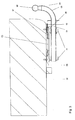
- the trailer coupling 01 according to the invention comprises a holder 03 fixedly connected to the underbody 02 of a vehicle and a coupling shank 04.
- a first end of the coupling shank 04 is mounted so as to be pivotable about its longitudinal axis in the holder 03.
- a coupling member 05 is arranged at a second end of the coupling shaft 04. This second end is provided with a bend 06.
- Fig. 3 can be seen that the coupling shaft 04 is aligned in the coupling position substantially in the vehicle longitudinal direction.
- the bending 06 having the end of the coupling shaft 04 is directed in the coupling position away from the roadway upwards.
- the coupling shaft 04 is disposed in a storage position below the vehicle.
- the bend 06 having the end of the coupling shaft 04 is arranged in this storage position substantially in a plane extending horizontally to the roadway.
- the holder 03 serving for supporting the coupling shaft 04 comprises a first bearing with an inner ring 07 and an outer ring 08.
- the inner ring 07 is preferably fastened to the underbody 02 of the vehicle via mechanical connecting means, for example screws 09. It has proven to be advantageous if the inner ring 07 is designed as a sheet metal forming part.
- On the outer ring 08 two opposing second bearings 11 are arranged. These second bearings 11 are used to support the coupling shaft 04.
- the first and / or the second bearing may be rolling or plain bearings.
- the outer ring 08 of the first bearing has a toothing 12 opposite the first end of the coupling shaft.
- This toothing 12 which may for example be designed as a worm wheel, is in engagement with a toothed wheel 13.
- the toothing 12 and the toothed wheel 13 form a first adjusting means, which serves to pivot the coupling shaft about a vertical axis.
- the gear 13 can be driven by a motor 14. Alternatively, a manual drive can be done.
- a rotation of the gear 13 causes a rotation of the outer ring 08 of the first bearing and thereby pivoting out of the coupling shaft 04 from the bottom 02 and a pivoting of the coupling shaft 04.
- the outer ring 08 can preferably be rotated by about 90 °. As a result of this rotation of the coupling shaft 04 is aligned in the swinging out substantially in the vehicle longitudinal direction.
- the inner ring 07 of the first bearing is provided with a toothing 16.
- the toothing 16 can be brought into engagement with a toothing 17 on the coupling shaft 04.
- These two gears 16, 17 together form a second adjusting means for rotating the coupling shaft 04 about its longitudinal axis.
- For engagement of the two gears 16, 17 occurs when pivoted out of the underbody 02 clutch shaft 04.
- the time required to erect the coupling member 05 space is available.
- the coupling member 05 is in dome position or leaves the coupling position when the clutch is to be pivoted back into the storage position.
- a rotation about 90 ° about the longitudinal axis of the coupling shaft 04 has proven to be particularly favorable.
- a socket 18 is arranged, which serves for the power supply of the coupling to be coupled to the trailer (not shown).
- the socket 18 is pivoted together with the coupling shaft 04 from the subfloor 02 or pivoted under the vehicle when the storage position is taken.
- the outer ring 08 of the first bearing may further comprise a protective cover 19.
- the protective cover 19 is used in the storage position pivoted coupling shaft 04 for closing the resulting opening and thus protects them from contamination.
- the pivoting of the trailer coupling according to the invention can be removed from the storage position to the coupling position.
- the motor 14 drives the gear 13.
- a rotation of the outer ring 08 of the first bearing and thus a pivoting of the coupling shaft 04 from the underbody 02 of the vehicle is effected.
- the toothings 16, 17 of the inner race 07 of the first bearing and of the coupling shaft 04 interlock with one another, which causes an elevation of the coupling member 05 during further pivoting.
- the trailer hitch is now ready for use.
- the coupling shaft 04 is aligned in the fully extended state substantially in the vehicle longitudinal direction and the coupling member 05 is directed away from the roadway upwards.
Landscapes
- Engineering & Computer Science (AREA)
- Transportation (AREA)
- Mechanical Engineering (AREA)
- Body Structure For Vehicles (AREA)
- Rolling Contact Bearings (AREA)
Abstract
Claims (15)
- Dispositif d'attelage pour remorque (01) pour un véhicule, comprenant une tige d'attelage (04) et comprenant un support relié fixement à un dessous de caisse (02) du véhicule, le support comprenant un premier et un deuxième moyen de réglage pour faire pivoter la tige d'attelage (04) dans une position d'attelage et dans une position de rangement, le premier moyen de réglage servant à faire pivoter la tige d'attelage (04) autour d'un axe vertical et le deuxième moyen de réglage servant à faire pivoter la tige d'attelage (04) autour de son axe longitudinal, caractérisé en ce quea. un premier palier comprend une première bague de palier (07) reliée au dessous de caisse (02) et une deuxième bague de palier (08) rotative,b. la tige d'attelage (04) est disposée, de manière pivotante autour de son axe longitudinal, sur la deuxième bague de palier (08) rotative du premier palier,c. la première bague de palier (07) fixe du premier palier est reliée, par l'intermédiaire du deuxième moyen de réglage, à la tige d'attelage (04) pivotée vers l'extérieur hors du dessous de caisse (02),une rotation de la deuxième bague de palier (08) du premier palier et un actionnement du deuxième moyen de réglage permettant un pivotement de la tige d'attelage (04) de la position de rangement à la position d'attelage et inversement.
- Dispositif d'attelage pour remorque (01) selon la revendication 1, caractérisé en ce que la première bague de palier est réalisée en tant que bague intérieure (07) et la deuxième bague de palier est réalisée en tant que bague extérieure (08).
- Dispositif d'attelage pour remorque (01) selon la revendication 2, caractérisé en ce que la bague extérieure (08) du premier palier peut tourner d'environ 90°.
- Dispositif d'attelage pour remorque (01) selon l'une quelconque des revendications 1 à 3, caractérisé en ce que le deuxième moyen de réglage provoque une rotation d'environ 90° autour de l'axe longitudinal de la tige d'attelage (04).
- Dispositif d'attelage pour remorque (01) selon l'une quelconque des revendications 2 à 4, caractérisé en ce que la bague extérieure (08) du premier palier comprend en tant que premier moyen de réglage une denture (12) qui fait face à la première extrémité de la tige d'attelage (04), et en ce que cette denture (12) est en prise avec une roue dentée (13).
- Dispositif d'attelage pour remorque (01) selon la revendication 5, caractérisé en ce que la denture de la bague extérieure (08) du premier palier est réalisée en tant que roue à denture hélicoïdale.
- Dispositif d'attelage pour remorque (01) selon la revendication 5 ou 6, caractérisé en ce que la roue dentée (13) peut être entraînée manuellement.
- Dispositif d'attelage pour remorque (01) selon la revendication 5 ou 6, caractérisé en ce que la roue dentée (13) peut être entraînée au moyen d'un moteur (14).
- Dispositif d'attelage pour remorque (01) selon l'une quelconque des revendications 2 à 8, caractérisé en ce que le deuxième moyen de réglage comporte, pour la rotation de la tige d'attelage (04), une denture (16) sur la bague intérieure (07) du premier palier et une denture (17) sur la tige d'attelage (04) qui peut être amenée en prise avec cette denture (16), la denture (17) sur la tige d'attelage (04) venant en prise dans la denture (16) sur la bague intérieure (07) du premier palier lorsque la tige d'attelage (04) est pivotée vers l'extérieur hors du dessous de caisse (02).
- Dispositif d'attelage pour remorque (01) selon l'une quelconque des revendications 2 à 9, caractérisé en ce qu'une prise de courant (18) est disposée sur la bague extérieure (08) du premier palier.
- Dispositif d'attelage pour remorque (01) selon l'une quelconque des revendications 1 à 10, caractérisé en ce que la première bague de palier (07) du premier palier est fixée au dessous de caisse (02) du véhicule grâce à des moyens de liaison mécaniques (09).
- Dispositif d'attelage pour remorque (01) selon l'une quelconque des revendications 1 à 11, caractérisé en ce que deux deuxièmes paliers (11) se faisant face sont disposés sur la deuxième bague de palier (08) rotative du premier palier, les deuxièmes paliers (11) servant au montage de la tige d'attelage (04).
- Dispositif d'attelage pour remorque (01) selon la revendication 12, caractérisé en ce que les deuxièmes paliers (11) sont des paliers à roulement ou des paliers lisses.
- Dispositif d'attelage pour remorque (01) selon l'une quelconque des revendications 1 à 13, caractérisé en ce que le premier palier (07, 08) est un palier à roulement ou un palier lisse.
- Dispositif d'attelage pour remorque (01) selon l'une quelconque des revendications 1 à 14, caractérisé en ce qu'un couvercle de protection (19), qui est destiné à fermer une ouverture se créant lors du pivotement de la tige d'attelage (04) dans la position de rangement, est disposé sur la deuxième bague de palier (08) rotative du premier palier.
Applications Claiming Priority (2)
| Application Number | Priority Date | Filing Date | Title |
|---|---|---|---|
| DE200810014135 DE102008014135A1 (de) | 2008-03-13 | 2008-03-13 | Verschwenkbare Anhängerkupplung |
| PCT/EP2009/001654 WO2009112217A1 (fr) | 2008-03-13 | 2009-03-07 | Dispositif d'attelage pivotant pour remorque |
Publications (2)
| Publication Number | Publication Date |
|---|---|
| EP2265451A1 EP2265451A1 (fr) | 2010-12-29 |
| EP2265451B1 true EP2265451B1 (fr) | 2012-05-30 |
Family
ID=40521877
Family Applications (1)
| Application Number | Title | Priority Date | Filing Date |
|---|---|---|---|
| EP09719485A Not-in-force EP2265451B1 (fr) | 2008-03-13 | 2009-03-07 | Dispositif d'attelage pivotant pour remorque |
Country Status (3)
| Country | Link |
|---|---|
| EP (1) | EP2265451B1 (fr) |
| DE (1) | DE102008014135A1 (fr) |
| WO (1) | WO2009112217A1 (fr) |
Families Citing this family (2)
| Publication number | Priority date | Publication date | Assignee | Title |
|---|---|---|---|---|
| DE102018204535A1 (de) * | 2018-03-26 | 2019-09-26 | Audi Ag | Wagenhebersystem und Wagenheber |
| AT524223B1 (de) * | 2021-04-29 | 2022-04-15 | Karl Wagner | Vorrichtung zum Aufnehmen eines Fahrradträgers |
Family Cites Families (10)
| Publication number | Priority date | Publication date | Assignee | Title |
|---|---|---|---|---|
| FR2227739A5 (en) | 1973-04-25 | 1974-11-22 | Gumuchian Pierre | Retracting drawgear for road type trailers - can be housed under trailer chassis when not in use |
| FR2450167A1 (fr) | 1979-02-27 | 1980-09-26 | Oppermann Rene | Dispositif d'attelage escamotable pour remorque |
| US6712381B1 (en) | 1999-10-29 | 2004-03-30 | Wing Enterprises, Inc. | Pivoting, underslung, stowaway, hitch mount |
| DE10004523A1 (de) | 2000-02-02 | 2001-08-09 | Fac Frank Abels Consult & Tech | Anhängerkupplung |
| DE20003480U1 (de) | 2000-02-25 | 2000-05-31 | Sauermann Hans | Anhängerkupplung für ein Fahrzeug, insbesondere für einen Personenkraftwagen |
| DE10108382A1 (de) | 2001-02-21 | 2002-09-12 | Daimler Chrysler Ag | Bewegliche Anhängerkupplung zur Vermeidung von Pendelbewegungen bei Fahrzeuggespannen |
| DE50302195D1 (de) * | 2002-02-28 | 2006-04-06 | Kober Ag | Schwenkbare anhängevorrichtung für zugfahrzeuge |
| DE102004004504A1 (de) | 2004-01-22 | 2005-08-18 | Oris Fahrzeugteile Hans Riehle Gmbh | Anhängekupplung |
| DE102004021895B4 (de) | 2004-05-04 | 2006-05-11 | Daimlerchrysler Ag | Anhängekupplung für ein Fahrzeug |
| DE202006011346U1 (de) * | 2006-07-20 | 2007-11-22 | Al-Ko Kober Ag | Schwenkbare Anhängevorrichtung für Zugfahrzeuge |
-
2008
- 2008-03-13 DE DE200810014135 patent/DE102008014135A1/de not_active Withdrawn
-
2009
- 2009-03-07 WO PCT/EP2009/001654 patent/WO2009112217A1/fr active Application Filing
- 2009-03-07 EP EP09719485A patent/EP2265451B1/fr not_active Not-in-force
Also Published As
| Publication number | Publication date |
|---|---|
| DE102008014135A1 (de) | 2009-09-17 |
| EP2265451A1 (fr) | 2010-12-29 |
| WO2009112217A1 (fr) | 2009-09-17 |
Similar Documents
| Publication | Publication Date | Title |
|---|---|---|
| EP0850147B2 (fr) | Dispositif d'attelage de remorque pour vehicules automobiles | |
| EP1435305B1 (fr) | Attelage de remorque | |
| EP1880879B1 (fr) | Dispositif d'attelage pivotant pour tracteurs | |
| EP1902871B1 (fr) | Attelage | |
| EP3820740B1 (fr) | Dispositif de vision arriere et vehicule automobile avec un tel dispositif | |
| DE102013007114A1 (de) | Anhängekupplung | |
| EP1905617B1 (fr) | Attelage | |
| DE102009045290A1 (de) | Taumelkugelgelenk | |
| EP2289743B1 (fr) | Appui de levage | |
| EP2265451B1 (fr) | Dispositif d'attelage pivotant pour remorque | |
| EP3867133A1 (fr) | Dispositif de levage pour déplacement rotatif d'un véhicule à moteur | |
| DE202009011491U1 (de) | Fahrgestell | |
| DE102013007122A1 (de) | Anhängekupplung | |
| EP1541385A1 (fr) | Attache remorque | |
| DE102018005268B4 (de) | Vorrichtung zum Umklappen einer Sitzlehne eines Fahrzeugsitzes | |
| EP2799261B1 (fr) | Attelage | |
| DE102012023571B4 (de) | Kippeinrichtung zum Kippen eines Fahrerhauses und Nutzfahrzeug | |
| DE102007033599B3 (de) | Hilfsantriebseinrichtung für antriebslose Fahrzeuganhänger, insbesondere Caravan-Rangierhilfe | |
| DE202004006666U1 (de) | Anhängerkupplung | |
| EP3287347B1 (fr) | Entraînement d'assistance pour une remorque et remorque | |
| DE102012011070A1 (de) | Betätigungssystem für eine Anhängekupplung eines Kraftfahrzeugs | |
| DE102012011069A1 (de) | Betätigungssystem für eine Anhängekupplung eines Kraftfahrzeugs | |
| DE202019107144U1 (de) | Ausfahrbare Trittstufe | |
| DE102014005881A1 (de) | Anhängekupplung | |
| EP2796305B1 (fr) | Attelage |
Legal Events
| Date | Code | Title | Description |
|---|---|---|---|
| PUAI | Public reference made under article 153(3) epc to a published international application that has entered the european phase |
Free format text: ORIGINAL CODE: 0009012 |
|
| 17P | Request for examination filed |
Effective date: 20101013 |
|
| AK | Designated contracting states |
Kind code of ref document: A1 Designated state(s): AT BE BG CH CY CZ DE DK EE ES FI FR GB GR HR HU IE IS IT LI LT LU LV MC MK MT NL NO PL PT RO SE SI SK TR |
|
| AX | Request for extension of the european patent |
Extension state: AL BA RS |
|
| DAX | Request for extension of the european patent (deleted) | ||
| GRAP | Despatch of communication of intention to grant a patent |
Free format text: ORIGINAL CODE: EPIDOSNIGR1 |
|
| RAP1 | Party data changed (applicant data changed or rights of an application transferred) |
Owner name: SCHAEFFLER TECHNOLOGIES AG & CO. KG |
|
| GRAS | Grant fee paid |
Free format text: ORIGINAL CODE: EPIDOSNIGR3 |
|
| GRAA | (expected) grant |
Free format text: ORIGINAL CODE: 0009210 |
|
| AK | Designated contracting states |
Kind code of ref document: B1 Designated state(s): AT BE BG CH CY CZ DE DK EE ES FI FR GB GR HR HU IE IS IT LI LT LU LV MC MK MT NL NO PL PT RO SE SI SK TR |
|
| REG | Reference to a national code |
Ref country code: GB Ref legal event code: FG4D Free format text: NOT ENGLISH |
|
| REG | Reference to a national code |
Ref country code: CH Ref legal event code: EP |
|
| REG | Reference to a national code |
Ref country code: AT Ref legal event code: REF Ref document number: 559897 Country of ref document: AT Kind code of ref document: T Effective date: 20120615 |
|
| REG | Reference to a national code |
Ref country code: IE Ref legal event code: FG4D Free format text: LANGUAGE OF EP DOCUMENT: GERMAN |
|
| REG | Reference to a national code |
Ref country code: DE Ref legal event code: R096 Ref document number: 502009003676 Country of ref document: DE Effective date: 20120726 |
|
| REG | Reference to a national code |
Ref country code: NL Ref legal event code: VDEP Effective date: 20120530 |
|
| REG | Reference to a national code |
Ref country code: LT Ref legal event code: MG4D Effective date: 20120530 |
|
| PG25 | Lapsed in a contracting state [announced via postgrant information from national office to epo] |
Ref country code: IS Free format text: LAPSE BECAUSE OF FAILURE TO SUBMIT A TRANSLATION OF THE DESCRIPTION OR TO PAY THE FEE WITHIN THE PRESCRIBED TIME-LIMIT Effective date: 20120930 Ref country code: FI Free format text: LAPSE BECAUSE OF FAILURE TO SUBMIT A TRANSLATION OF THE DESCRIPTION OR TO PAY THE FEE WITHIN THE PRESCRIBED TIME-LIMIT Effective date: 20120530 Ref country code: LT Free format text: LAPSE BECAUSE OF FAILURE TO SUBMIT A TRANSLATION OF THE DESCRIPTION OR TO PAY THE FEE WITHIN THE PRESCRIBED TIME-LIMIT Effective date: 20120530 Ref country code: CY Free format text: LAPSE BECAUSE OF FAILURE TO SUBMIT A TRANSLATION OF THE DESCRIPTION OR TO PAY THE FEE WITHIN THE PRESCRIBED TIME-LIMIT Effective date: 20120530 Ref country code: SE Free format text: LAPSE BECAUSE OF FAILURE TO SUBMIT A TRANSLATION OF THE DESCRIPTION OR TO PAY THE FEE WITHIN THE PRESCRIBED TIME-LIMIT Effective date: 20120530 Ref country code: NO Free format text: LAPSE BECAUSE OF FAILURE TO SUBMIT A TRANSLATION OF THE DESCRIPTION OR TO PAY THE FEE WITHIN THE PRESCRIBED TIME-LIMIT Effective date: 20120830 |
|
| PG25 | Lapsed in a contracting state [announced via postgrant information from national office to epo] |
Ref country code: LV Free format text: LAPSE BECAUSE OF FAILURE TO SUBMIT A TRANSLATION OF THE DESCRIPTION OR TO PAY THE FEE WITHIN THE PRESCRIBED TIME-LIMIT Effective date: 20120530 Ref country code: SI Free format text: LAPSE BECAUSE OF FAILURE TO SUBMIT A TRANSLATION OF THE DESCRIPTION OR TO PAY THE FEE WITHIN THE PRESCRIBED TIME-LIMIT Effective date: 20120530 Ref country code: GR Free format text: LAPSE BECAUSE OF FAILURE TO SUBMIT A TRANSLATION OF THE DESCRIPTION OR TO PAY THE FEE WITHIN THE PRESCRIBED TIME-LIMIT Effective date: 20120831 Ref country code: HR Free format text: LAPSE BECAUSE OF FAILURE TO SUBMIT A TRANSLATION OF THE DESCRIPTION OR TO PAY THE FEE WITHIN THE PRESCRIBED TIME-LIMIT Effective date: 20120530 |
|
| PG25 | Lapsed in a contracting state [announced via postgrant information from national office to epo] |
Ref country code: NL Free format text: LAPSE BECAUSE OF FAILURE TO SUBMIT A TRANSLATION OF THE DESCRIPTION OR TO PAY THE FEE WITHIN THE PRESCRIBED TIME-LIMIT Effective date: 20120530 Ref country code: DK Free format text: LAPSE BECAUSE OF FAILURE TO SUBMIT A TRANSLATION OF THE DESCRIPTION OR TO PAY THE FEE WITHIN THE PRESCRIBED TIME-LIMIT Effective date: 20120530 Ref country code: SK Free format text: LAPSE BECAUSE OF FAILURE TO SUBMIT A TRANSLATION OF THE DESCRIPTION OR TO PAY THE FEE WITHIN THE PRESCRIBED TIME-LIMIT Effective date: 20120530 Ref country code: CZ Free format text: LAPSE BECAUSE OF FAILURE TO SUBMIT A TRANSLATION OF THE DESCRIPTION OR TO PAY THE FEE WITHIN THE PRESCRIBED TIME-LIMIT Effective date: 20120530 Ref country code: EE Free format text: LAPSE BECAUSE OF FAILURE TO SUBMIT A TRANSLATION OF THE DESCRIPTION OR TO PAY THE FEE WITHIN THE PRESCRIBED TIME-LIMIT Effective date: 20120530 Ref country code: RO Free format text: LAPSE BECAUSE OF FAILURE TO SUBMIT A TRANSLATION OF THE DESCRIPTION OR TO PAY THE FEE WITHIN THE PRESCRIBED TIME-LIMIT Effective date: 20120530 |
|
| PG25 | Lapsed in a contracting state [announced via postgrant information from national office to epo] |
Ref country code: PT Free format text: LAPSE BECAUSE OF FAILURE TO SUBMIT A TRANSLATION OF THE DESCRIPTION OR TO PAY THE FEE WITHIN THE PRESCRIBED TIME-LIMIT Effective date: 20121001 Ref country code: IT Free format text: LAPSE BECAUSE OF FAILURE TO SUBMIT A TRANSLATION OF THE DESCRIPTION OR TO PAY THE FEE WITHIN THE PRESCRIBED TIME-LIMIT Effective date: 20120530 Ref country code: PL Free format text: LAPSE BECAUSE OF FAILURE TO SUBMIT A TRANSLATION OF THE DESCRIPTION OR TO PAY THE FEE WITHIN THE PRESCRIBED TIME-LIMIT Effective date: 20120530 |
|
| PLBE | No opposition filed within time limit |
Free format text: ORIGINAL CODE: 0009261 |
|
| STAA | Information on the status of an ep patent application or granted ep patent |
Free format text: STATUS: NO OPPOSITION FILED WITHIN TIME LIMIT |
|
| PG25 | Lapsed in a contracting state [announced via postgrant information from national office to epo] |
Ref country code: ES Free format text: LAPSE BECAUSE OF FAILURE TO SUBMIT A TRANSLATION OF THE DESCRIPTION OR TO PAY THE FEE WITHIN THE PRESCRIBED TIME-LIMIT Effective date: 20120910 |
|
| 26N | No opposition filed |
Effective date: 20130301 |
|
| REG | Reference to a national code |
Ref country code: DE Ref legal event code: R097 Ref document number: 502009003676 Country of ref document: DE Effective date: 20130301 |
|
| PG25 | Lapsed in a contracting state [announced via postgrant information from national office to epo] |
Ref country code: BG Free format text: LAPSE BECAUSE OF FAILURE TO SUBMIT A TRANSLATION OF THE DESCRIPTION OR TO PAY THE FEE WITHIN THE PRESCRIBED TIME-LIMIT Effective date: 20120830 |
|
| BERE | Be: lapsed |
Owner name: SCHAEFFLER TECHNOLOGIES A.G. & CO. KG Effective date: 20130331 |
|
| PG25 | Lapsed in a contracting state [announced via postgrant information from national office to epo] |
Ref country code: MC Free format text: LAPSE BECAUSE OF NON-PAYMENT OF DUE FEES Effective date: 20130331 |
|
| REG | Reference to a national code |
Ref country code: CH Ref legal event code: PL |
|
| GBPC | Gb: european patent ceased through non-payment of renewal fee |
Effective date: 20130307 |
|
| REG | Reference to a national code |
Ref country code: FR Ref legal event code: ST Effective date: 20131129 |
|
| REG | Reference to a national code |
Ref country code: IE Ref legal event code: MM4A |
|
| PG25 | Lapsed in a contracting state [announced via postgrant information from national office to epo] |
Ref country code: GB Free format text: LAPSE BECAUSE OF NON-PAYMENT OF DUE FEES Effective date: 20130307 Ref country code: BE Free format text: LAPSE BECAUSE OF NON-PAYMENT OF DUE FEES Effective date: 20130331 Ref country code: IE Free format text: LAPSE BECAUSE OF NON-PAYMENT OF DUE FEES Effective date: 20130307 Ref country code: CH Free format text: LAPSE BECAUSE OF NON-PAYMENT OF DUE FEES Effective date: 20130331 Ref country code: FR Free format text: LAPSE BECAUSE OF NON-PAYMENT OF DUE FEES Effective date: 20130402 Ref country code: LI Free format text: LAPSE BECAUSE OF NON-PAYMENT OF DUE FEES Effective date: 20130331 |
|
| REG | Reference to a national code |
Ref country code: DE Ref legal event code: R081 Ref document number: 502009003676 Country of ref document: DE Owner name: SCHAEFFLER TECHNOLOGIES AG & CO. KG, DE Free format text: FORMER OWNER: SCHAEFFLER TECHNOLOGIES AG & CO. KG, 91074 HERZOGENAURACH, DE Effective date: 20140218 Ref country code: DE Ref legal event code: R081 Ref document number: 502009003676 Country of ref document: DE Owner name: SCHAEFFLER TECHNOLOGIES GMBH & CO. KG, DE Free format text: FORMER OWNER: SCHAEFFLER TECHNOLOGIES AG & CO. KG, 91074 HERZOGENAURACH, DE Effective date: 20140218 |
|
| PG25 | Lapsed in a contracting state [announced via postgrant information from national office to epo] |
Ref country code: MT Free format text: LAPSE BECAUSE OF FAILURE TO SUBMIT A TRANSLATION OF THE DESCRIPTION OR TO PAY THE FEE WITHIN THE PRESCRIBED TIME-LIMIT Effective date: 20120530 |
|
| REG | Reference to a national code |
Ref country code: DE Ref legal event code: R081 Ref document number: 502009003676 Country of ref document: DE Owner name: SCHAEFFLER TECHNOLOGIES AG & CO. KG, DE Free format text: FORMER OWNER: SCHAEFFLER TECHNOLOGIES GMBH & CO. KG, 91074 HERZOGENAURACH, DE Effective date: 20150407 |
|
| REG | Reference to a national code |
Ref country code: AT Ref legal event code: MM01 Ref document number: 559897 Country of ref document: AT Kind code of ref document: T Effective date: 20140307 |
|
| PG25 | Lapsed in a contracting state [announced via postgrant information from national office to epo] |
Ref country code: TR Free format text: LAPSE BECAUSE OF FAILURE TO SUBMIT A TRANSLATION OF THE DESCRIPTION OR TO PAY THE FEE WITHIN THE PRESCRIBED TIME-LIMIT Effective date: 20120530 |
|
| PG25 | Lapsed in a contracting state [announced via postgrant information from national office to epo] |
Ref country code: MK Free format text: LAPSE BECAUSE OF FAILURE TO SUBMIT A TRANSLATION OF THE DESCRIPTION OR TO PAY THE FEE WITHIN THE PRESCRIBED TIME-LIMIT Effective date: 20120530 Ref country code: HU Free format text: LAPSE BECAUSE OF FAILURE TO SUBMIT A TRANSLATION OF THE DESCRIPTION OR TO PAY THE FEE WITHIN THE PRESCRIBED TIME-LIMIT; INVALID AB INITIO Effective date: 20090307 Ref country code: LU Free format text: LAPSE BECAUSE OF NON-PAYMENT OF DUE FEES Effective date: 20130307 |
|
| PG25 | Lapsed in a contracting state [announced via postgrant information from national office to epo] |
Ref country code: AT Free format text: LAPSE BECAUSE OF NON-PAYMENT OF DUE FEES Effective date: 20140307 |
|
| PGFP | Annual fee paid to national office [announced via postgrant information from national office to epo] |
Ref country code: DE Payment date: 20170531 Year of fee payment: 9 |
|
| REG | Reference to a national code |
Ref country code: DE Ref legal event code: R119 Ref document number: 502009003676 Country of ref document: DE |
|
| PG25 | Lapsed in a contracting state [announced via postgrant information from national office to epo] |
Ref country code: DE Free format text: LAPSE BECAUSE OF NON-PAYMENT OF DUE FEES Effective date: 20181002 |
|
| P01 | Opt-out of the competence of the unified patent court (upc) registered |
Effective date: 20230522 |