EP2265088A2 - Induktionskochfeld - Google Patents
Induktionskochfeld Download PDFInfo
- Publication number
- EP2265088A2 EP2265088A2 EP10179112A EP10179112A EP2265088A2 EP 2265088 A2 EP2265088 A2 EP 2265088A2 EP 10179112 A EP10179112 A EP 10179112A EP 10179112 A EP10179112 A EP 10179112A EP 2265088 A2 EP2265088 A2 EP 2265088A2
- Authority
- EP
- European Patent Office
- Prior art keywords
- induction
- layer
- induction coils
- coils
- hob
- Prior art date
- Legal status (The legal status is an assumption and is not a legal conclusion. Google has not performed a legal analysis and makes no representation as to the accuracy of the status listed.)
- Granted
Links
- 230000006698 induction Effects 0.000 title claims abstract description 238
- 238000010411 cooking Methods 0.000 title claims abstract description 51
- 229910000859 α-Fe Inorganic materials 0.000 claims description 26
- 239000000758 substrate Substances 0.000 claims description 25
- 239000004020 conductor Substances 0.000 claims description 18
- 230000005291 magnetic effect Effects 0.000 claims description 6
- 239000000919 ceramic Substances 0.000 claims description 2
- 239000011521 glass Substances 0.000 claims description 2
- 239000002241 glass-ceramic Substances 0.000 claims description 2
- 238000011144 upstream manufacturing Methods 0.000 claims 1
- 230000000052 comparative effect Effects 0.000 description 3
- 239000003302 ferromagnetic material Substances 0.000 description 2
- 238000004519 manufacturing process Methods 0.000 description 2
- 238000010276 construction Methods 0.000 description 1
- 230000001419 dependent effect Effects 0.000 description 1
- 238000009434 installation Methods 0.000 description 1
Images




Classifications
-
- H—ELECTRICITY
- H05—ELECTRIC TECHNIQUES NOT OTHERWISE PROVIDED FOR
- H05B—ELECTRIC HEATING; ELECTRIC LIGHT SOURCES NOT OTHERWISE PROVIDED FOR; CIRCUIT ARRANGEMENTS FOR ELECTRIC LIGHT SOURCES, IN GENERAL
- H05B6/00—Heating by electric, magnetic or electromagnetic fields
- H05B6/02—Induction heating
- H05B6/10—Induction heating apparatus, other than furnaces, for specific applications
- H05B6/12—Cooking devices
- H05B6/1209—Cooking devices induction cooking plates or the like and devices to be used in combination with them
- H05B6/1245—Cooking devices induction cooking plates or the like and devices to be used in combination with them with special coil arrangements
-
- H—ELECTRICITY
- H05—ELECTRIC TECHNIQUES NOT OTHERWISE PROVIDED FOR
- H05B—ELECTRIC HEATING; ELECTRIC LIGHT SOURCES NOT OTHERWISE PROVIDED FOR; CIRCUIT ARRANGEMENTS FOR ELECTRIC LIGHT SOURCES, IN GENERAL
- H05B2213/00—Aspects relating both to resistive heating and to induction heating, covered by H05B3/00 and H05B6/00
- H05B2213/03—Heating plates made out of a matrix of heating elements that can define heating areas adapted to cookware randomly placed on the heating plate
-
- Y—GENERAL TAGGING OF NEW TECHNOLOGICAL DEVELOPMENTS; GENERAL TAGGING OF CROSS-SECTIONAL TECHNOLOGIES SPANNING OVER SEVERAL SECTIONS OF THE IPC; TECHNICAL SUBJECTS COVERED BY FORMER USPC CROSS-REFERENCE ART COLLECTIONS [XRACs] AND DIGESTS
- Y02—TECHNOLOGIES OR APPLICATIONS FOR MITIGATION OR ADAPTATION AGAINST CLIMATE CHANGE
- Y02B—CLIMATE CHANGE MITIGATION TECHNOLOGIES RELATED TO BUILDINGS, e.g. HOUSING, HOUSE APPLIANCES OR RELATED END-USER APPLICATIONS
- Y02B40/00—Technologies aiming at improving the efficiency of home appliances, e.g. induction cooking or efficient technologies for refrigerators, freezers or dish washers
Definitions
- the invention relates to an induction hob.
- an alternating magnetic field is generated by means of one or more induction coils.
- the induction coils are usually formed like a sheet and attached to the underside of a carrier substrate.
- a cooking container for the induction hob have at least partially ferromagnetic material. The alternating magnetic field heats the ferromagnetic material of the cooking vessel.
- the carrier substrate itself is not heated.
- the user can also use the carrier substrate as a work surface.
- the induction coils are arranged and formed on the underside of the carrier substrate such that a corresponding field is provided on the upper side of the carrier substrate for cooking containers of a certain size. The user thus does not have the opportunity to freely decide which cooking container will be positioned at which position on the induction hob.
- the essence of the invention is that two or more induction coils are arranged one above the other, in particular in layers or layers, such that at least two induction coils partially overlap. At least two induction coils are therefore not congruent, but have in a projection on one another, preferably in a projection direction perpendicular to the carrier, in the projection plane matching partial areas. This gives the user more options to choose the position of the cooking container on the induction hob. It is the induction coil or those induction coils are activated, which are located below the cooking vessel. The user can use a part of the induction hob, for example, as a work surface.
- At least one first layer with at least one induction coil, which is arranged below the carrier substrate, and at least one further layer, each with at least one induction coil, which is arranged below the first layer, are preferably provided on the carrier (substrate).
- the induction coils of one layer and the adjacent induction coils of the other layer or layers are preferably arranged partially overlapping one another.
- the induction coils are preceded by at least one selection circuit, by means of which induction coils selected according to a predetermined pattern are activated or can be activated.
- such induction coils are manually, semi-automatically or automatically selected, which are located below the cooking vessel.
- sensors may be provided for detecting the position of the cooking container.
- the selection circuit is designed or adjustable such that the overlapping arranged induction coils are not activated simultaneously or can be activated. This prevents the mutual magnetic interference of the induction coils.
- the unused induction coils are electrically decoupled, so that no circuits can be destroyed by induction currents.
- a programmable selection circuit can be provided that the selection circuit is programmed or programmable such that the overlapping arranged induction coils are not activated simultaneously or can be activated. As a result, the circuit complexity is reduced.
- the induction coils are at least partially formed as conductor tracks.
- the conductor tracks may be applied to the underside of the carrier substrate or a separate substrate. With the tracks, the induction hob can be easily and inexpensively manufactured.
- the induction coils are at least partially formed as conductor loops. Again, this is a simple and inexpensive construction.
- the induction coils are at least partially formed as circular conductor loops and / or conductor tracks.
- the induction coils may be at least partially formed as spiral conductor loops and / or conductor tracks.
- the induction coils of a layer are arranged as widely as possible. This increases on the one hand the electrical power and on the other hand, the number of positioning options for the cooking container.
- the induction coils of a layer have the same shape and / or the same size.
- all or almost all induction coils of the device have the same shape and / or size. This simplifies the manufacturing process and increases the number of positioning options for the cooking container.
- an induction coil of one layer and three induction coils of each further layer overlap.
- the induction hob comprises a ferrite layer having a plurality of ferrite elements.
- the ferrite layer can be arranged below the layers with the induction coils.
- the ferrite elements influence the course of the magnetic field lines.
- the ferrite elements are formed elongated.
- the ferrite elements can be arranged between two adjacent induction coils of one layer.
- the ferrite elements form a plurality of equilateral triangles. This fits perfectly with the circular or spiral induction coils.
- the selection circuit is preceded by at least one power supply circuit.
- an inverter circuit is provided as the power supply circuit.
- the carrier substrate is made of glass ceramic or glass or ceramic.
- Fig. 1 to Fig. 4 a preferred embodiment of the induction hob according to the invention is shown.
- the induction hob is incomplete.
- Fig. 1 are three lower layers, in Fig. 2 two lower layers and in Fig. 3 a lower layer of the induction hob is not shown.
- Fig. 1 shows a schematic plan view and sectional view of the induction hob with a carrier substrate 10 and a first layer 12.
- the sectional view illustrates the arrangement of the first layer 12 below the carrier substrate 10.
- the first layer comprises a plurality of induction coils 14.
- the induction coils 14 are arranged so that the carrier substrate is completely covered as possible.
- the induction coils 14 are shown as circles.
- the induction coils 14 are formed as circular conductor tracks or conductor loops.
- the induction coils 14 may also be formed as spiral-shaped conductor tracks or conductor loops.
- the induction coils 14 may also have an oval, elliptical, rectangular, hexagonal or octagonal contour. In principle, any desired contours for the induction coils 14 are possible, the carrier substrate 10 being covered as completely as possible by the induction coils 14.
- Fig. 3 shows the induction hob according to Fig. 2 in which additionally a third layer 20 with a plurality of induction coils 22 is shown.
- the inductors 22 of the third layer 20 are the same size as the inductors 14 of the first layer 12 and the inductors 18 of the second layer 16.
- the inductors 22 are arranged on the third layer 20 in the same pattern as the inductors 14 and 18 on the first Layer 12 and second layer 16. However, the third layer 20 is also displaced both with respect to the first layer 12 and with respect to the second layer 16.
- An induction coil 22 of the third layer 20 overlaps uniformly with three induction coils 14 of the first layer 12 and at the same time with three induction coils 18 of the second layer 16.
- the third layer 20 is arranged below the second layer 16.
- Fig. 4 is the induction hob according to Fig. 3 in which additionally a ferrite layer 24 with a plurality of ferrite elements 26 is shown.
- the ferrite layer 24 is disposed below the third layer 16.
- the ferrite elements 26 are elongate and their length corresponds approximately to the radius of the induction coils 14, 18 and 22.
- the ferrite elements 26 form a plurality of equilateral triangles. Each ferrite element 26 is located between two adjacent induction coils 14, 18 and 22, respectively.
- the ferrite elements 26 influence the course of the magnetic field lines.
- the induction hob has power supply circuits for the induction coils 14, 18 and 22, which are not shown in the drawings. Between the power supply circuits and the induction coils 14, 18 and 22, one or more selection circuits are provided, which are also not shown.
- the selection circuits establish the electrical connection between the power supply circuits and the induction coils 14, 18 and 22.
- the selection circuits activate those induction coils 14, 18 and 22, respectively, in the vicinity of which there is a cooking container. In this case, overlapping induction coils 14, 18 and 22 are never activated simultaneously.
- the number of power supply circuits is thus always smaller than that of the induction coils 14, 18 and 22. This is advantageous in terms of size and cost.
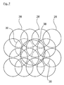
- Fig. 5 is a schematic plan view of a first application example according to the invention shown.
- the induction coils 28 and 30 are distributed over three layers which are arranged parallel to one another. Within a layer, the induction coils 28 and 30 are always arranged side by side and as widely as possible.
- the induction coils 28 and 30 in Fig. 5 all have a diameter of 140 mm.
- the cooking container 32 has a circular disk-shaped bottom surface with a diameter of 120 mm.
- the cooking container 32 is disposed above the induction coil 30, which is activated only. The remaining induction coils 28 are not activated.
- This illustration illustrates that due to the overlapping induction coils 28 and 30 there are numerous possibilities to position the cooking container on the induction hob according to the invention.
- the induction coils 28 and 30 have a power of about 1800 W.
- the power supply circuits are coupled to the inductors 28 and 30 via one or more selection circuits. Because the overlapping Induction coils 28 and 30 are never activated simultaneously, always fewer power supply circuits than induction coils 28 and 30 are required.
- Fig. 6 shows a comparative example of the cooking container 32 Fig. 5 on an induction hob, in which activated induction coils 36 and non-activated induction coils 34 are arranged in a conventional manner, ie non-overlapping.
- the induction coils 34 and 36 have a diameter of 80 mm and a power of about 500 W.
- a power supply circuit is required for each of the induction coils 34 and 36.
- Fig. 7 is a schematic plan view of a second application example according to the invention shown.
- a cooking container 38 on an induction hob with the overlapping induction coils 28 and 30.
- the induction coils 28 and 30 are as well as in Fig. 5 arranged and have a diameter of 140 mm.
- the cooking container 38 has a circular disk-shaped bottom surface with a diameter of 210 mm.
- the cooking container 38 is arranged above the two activated induction coils 30.
- the remaining induction coils 28 are not activated.
- the two activated induction coils 30 have a power of about 1800 W, so that the cooking container, a power of 3600 W is supplied.
- Fig. 8 shows a schematic plan view of a third application example according to the invention.
- the cooking container 38 is located on the same induction hob as in FIG Fig. 7 with the overlapping induction coils 28 and 30.
- the cooking container 38 with the bottom surface diameter of 210 mm is disposed above the three activated induction coils 30 which are arranged in the shape of an equilateral triangle.
- the remaining induction coils 28 are not activated.
- the three activated Induction coils 30 have a power of about 1800 W, so that the cooking container, a power of 5400 W is supplied.
- Fig. 7 and Fig. 8 illustrate the numerous possible positioning of the cooking container 38 on the induction hob.
- Fig. 9 is shown as the cooking container 38 on an induction hob with the conventional arrangement of the induction coils 34 and 36 according to Fig. 6 is positioned.
- the cooking container 38 whose bottom surface has the diameter of 210 mm, is arranged above seven activated induction coils 36. Since each induction coil 36 has a power of 500 W, the power of 3500 W is discharged to the cooking tank 38. This is significantly less than in Fig. 8 and also less than in Fig. 7 , However, in Fig. 9 seven power supply circuits are activated while in Fig. 7 only two and in Fig. 8 only three are activated.
- the induction hob according to the invention requires fewer power supply circuits than the conventional arrangement, thereby reducing the size and cost of the induction hob.
- the user has more options in the induction hob according to the invention than in the conventional arrangement to position one or more cooking containers.
- a larger surface portion of the induction hob according to the invention can be used as a work surface, so that the user has more options than in the conventional arrangement of the induction coils to design his workplace.
- the induction coils 14, 18 and 22 may also have different diameters within a layer 12, 16 and 20 and be arranged according to a predetermined pattern.
Landscapes
- Physics & Mathematics (AREA)
- Electromagnetism (AREA)
- Cookers (AREA)
- Surgical Instruments (AREA)
- Dry Shavers And Clippers (AREA)
- Polishing Bodies And Polishing Tools (AREA)
- General Induction Heating (AREA)
- General Preparation And Processing Of Foods (AREA)
- Apparatus Associated With Microorganisms And Enzymes (AREA)
Abstract
Description
- Die Erfindung betrifft ein Induktionskochfeld.
- Bei einem Induktionskochfeld wird mittels einer oder mehrerer Induktionspulen ein magnetisches Wechselfeld erzeugt. Die Induktionsspulen sind meist flächenartig ausgebildet und an der Unterseite eines Trägersubstrats angebracht. Ein Garbehälter für das Induktionskochfeld weisen zumindest teilweise ferromagnetisches Material auf. Das magnetische Wechselfeld erwärmt das ferromagnetische Material des Garbehälters.
- Das Trägersubstrat selbst wird dabei nicht erwärmt. Somit kann der Benutzer das Trägersubstrat auch als Arbeitsfläche verwenden. Üblicherweise sind die Induktionsspulen an der Unterseite des Trägersubstrats so angeordnet und ausgebildet, dass für Garbehälter mit einer bestimmten Größe ein entsprechendes Feld auf der Oberseite des Trägersubstrats vorgesehen ist. Der Benutzer hat somit nicht die Möglichkeit, frei zu entscheiden, welcher Garbehälter an welcher Stelle auf dem Induktionskochfeld positioniert wird.
- Es ist Aufgabe der Erfindung, ein Induktionskochfeld bereit zu stellen, bei dem der Garbehälter an unterschiedlichen Stellen auf dem Induktionskochfeld positionierbar ist, wobei eine optimale Energieübertragung vom Induktionskochfeld zum Garbehälter möglich ist.
- Diese Aufgabe wird durch den Gegenstand gemäß Patentanspruch 1 gelöst.
- Erfindungsgemäß ist ein Induktionskochfeld (für eine Gareinrichtung) vorgesehen, das Folgendes aufweist:
- einen Träger, dessen Oberseite zum Positionieren von wenigstens einem Garbehälter vorgesehen ist,
- mindestens eine erste Induktionsspule (14), die unterhalb oder an oder unter einer Unterseite des Trägers angeordnet ist, und
- mindestens eine zweite Induktionsspule, die unterhalb der ersten Induktionsspule(n) oder an deren von dem Träger abgewandten Unterseite angeordnet ist, wobei
- die erste(n) Induktionsspule(n) und die zweite(n), vorzugsweise benachbarte(n), Induktionsspule(n) einander teilweise überlappend angeordnet sind.
- Der Kern der Erfindung liegt darin, dass zwei oder mehr Induktionsspulen derart, insbesondere in Lagen oder Schichten, übereinander angeordnet sind, dass sich wenigstens zwei Induktionsspulen teilweise überlappen. Wenigstens zwei Induktionsspulen sind also nicht deckungsgleich, weisen jedoch in einer Projektion aufeinander, vorzugsweise in einer Projektionsrichtung senkrecht zum Träger, in der Projektionsebene übereinstimmende Teilbereiche auf. Dadurch hat der Benutzer mehr Möglichkeiten, die Position des Garbehälters auf dem Induktionskochfeld zu wählen. Es wird diejenige Induktionsspule bzw. es werden diejenigen Induktionsspulen aktiviert, die sich unterhalb des Garbehälters befinden. Der Benutzer kann einen Teil des Induktionskochfeldes beispielsweise als Arbeitfläche nutzen.
- Bevorzugt sind wenigstens eine erste Schicht mit mindestens einer Induktionsspule, die unterhalb des Trägersubstrats angeordnet ist, und wenigstens eine weitere Schicht mit jeweils mindestens einer Induktionsspule, die unterhalb der ersten Schicht angeordnet ist, an dem Träger(substrat) vorgesehen. Es sind nun vorzugsweise die Induktionsspulen der einen Schicht und die benachbarten Induktionsspulen der jeweils anderen Schicht bzw. Schichten einander teilweise überlappend angeordnet. Vorzugsweise ist den Induktionsspulen wenigstens eine Selektionsschaltung vorgeschaltet, durch die nach einem vorbestimmten Schema ausgewählte Induktionsspulen aktiviert werden oder aktivierbar sind. Zweckmäßigerweise werden solche Induktionsspulen manuell, halbautomatisch oder automatisch ausgewählt, die sich unterhalb des Garbehälters befinden. Dazu können Sensoren zum Erfassen der Position des Garbehälters vorgesehen sein.
- Beispielsweise ist die Selektionsschaltung derart ausgebildet oder einstellbar, dass die überlappend angeordneten Induktionsspulen nicht gleichzeitig aktiviert werden oder aktivierbar sind. Dadurch wird die gegenseitige magnetische Störung der Induktionsspulen verhindert. Außerdem werden die nicht benutzten Induktionsspulen elektrisch abgekoppelt, so dass keine Schaltungen durch Induktionsströme zerstört werden können.
- Bei einer programmierbaren Selektionsschaltung kann vorgesehen sein, dass die Selektionsschaltung derart programmiert oder programmierbar ist, dass die überlappend angeordneten Induktionsspulen nicht gleichzeitig aktiviert werden oder aktivierbar sind. Dadurch wird auch der schaltungstechnische Aufwand verringert.
- Weiterhin kann vorgesehen sein, dass die Induktionsspulen zumindest teilweise als Leiterbahnen ausgebildet sind. Die Leiterbahnen können an der Unterseite des Trägersubstrats oder eines separaten Substrats aufgebracht sein. Mit den Leiterbahnen lässt sich das Induktionskochfeld einfach und kostengünstig herstellen.
- Ebenso kann vorgesehen sein, dass die Induktionsspulen zumindest teilweise als Leiterschleifen ausgebildet sind. Auch dies ist eine einfache und kostengünstige Bauweise.
- Beispielsweise sind die Induktionsspulen zumindest teilweise als kreisförmige Leiterschleifen und/oder Leiterbahnen ausgebildet.
- Alternativ dazu können die Induktionsspulen zumindest teilweise als spiralförmige Leiterschleifen und/oder Leiterbahnen ausgebildet sein.
- Vorzugsweise sind die Induktionsspulen einer Schicht möglichst flächendeckend angeordnet. Dies erhöht einerseits die elektrische Leistung und andererseits die Anzahl der Positioniermöglichkeiten für den Garbehälter.
- Zweckmäßigerweise ist vorgesehen, dass die Induktionsspulen einer Schicht die gleiche Form und/oder die gleiche Größe aufweisen. Zweckmäßigerweise haben alle oder fast alle Induktionsspulen der Vorrichtung die gleiche Form und/oder die gleiche Größe. Dies vereinfacht den Herstellungsprozess und erhöht die Anzahl der Positioniermöglichkeiten für den Garbehälter.
- Bei der bevorzugten Ausführungsform ist vorgesehen, dass eine Induktionsspule von einer Schicht und drei Induktionsspulen von einer weiteren Schicht sich überlappen. Dies ist die optimale geometrische Anordnung für die Induktionsspulen.
- Weiterhin kann vorgesehen sein, dass eine Induktionsspule von einer Schicht und drei Induktionsspulen von jeder weiteren Schicht sich überlappen. Je höher die Anzahl der Schichten ist, desto höher ist auch das Auflösungsvermögen des Induktionskochfeldes.
- Vorzugsweise umfasst das Induktionskochfeld eine Ferritschicht mit einer Vielzahl Ferritelementen. Dabei kann die Ferritschicht unterhalb der Schichten mit den Induktionsspulen angeordnet sein. Die Ferritelemente beeinflussen den Verlauf der magnetischen Feldlinien.
- Beispielsweise sind die Ferritelemente langgestreckt ausgebildet. Dabei können die Ferritelemente zwischen zwei benachbarten Induktionsspulen von einer Schicht angeordnet sein.
- Bei der bevorzugten Ausführungsform ist vorgesehen, dass die Ferritelemente eine Vielzahl gleichseitiger Dreiecke bilden. Dies passt ideal zu den kreis- oder spiralförmigen Induktionsspulen.
- Beispielsweise haben die Induktionsspulen einen Durchmesser zwischen 100 mm und 200 mm. Dies ist optimal geeignet für die Garbehälter mit üblicher Größe.
- Bei der bevorzugten Ausführungsform ist vorgesehen, dass der Selektionsschaltung wenigstens eine Stromversorgungsschaltung vorgeschaltet ist. Beispielsweise ist als Stromversorgungsschaltung eine Inverterschaltung vorgesehen.
- Vorzugsweise ist die Anzahl der Stromversorgungsschaltungen niedriger als die Anzahl der Induktionsspulen. Dadurch werden die Baugröße des Induktionskochfeldes und die Herstellungskosten reduziert.
- Bei der bevorzugten Ausführungsform ist vorgesehen, dass das Trägersubstrat aus Glaskeramik oder Glas oder Keramik hergestellt ist.
- Weitere Merkmale, Vorteile und besondere Ausführungsformen der Erfindung sind Gegenstand der abhängigen Ansprüche.
- Das Induktionskochfeld gemäß der Erfindung wird nachstehend anhand beispielhafter Ausführungsformen und unter Bezugnahme auf die beigefügten Zeichnungen näher erläutert. Es zeigen:
- Fig. 1
- eine schematische Draufsicht und Schnittansicht eines Trä- gersubstrats und einer Schicht mit Induktionsspulen gemäß der Erfindung,
- Fig. 2
- eine schematische Draufsicht und Schnittansicht des Träger- substrats und zwei Schichten mit Induktionsspulen gemäß der Erfindung,
- Fig. 3
- eine schematische Draufsicht und Schnittansicht des Träger- substrats und drei Schichten mit Induktionsspulen gemäß der Erfindung,
- Fig. 4
- eine schematische Draufsicht und Schnittansicht des Träger- substrats und drei Schichten mit Induktionsspulen und einer Ferritschicht mit Ferritelementen gemäß der Erfindung,
- Fig. 5
- eine schematische Draufsicht eines ersten Anwendungsbei- spiels mit einem Garbehälter auf drei Schichten mit Indukti- onsspulen gemäß der Erfindung,
- Fig. 6
- eine schematische Draufsicht eines Vergleichsbeispiels zu
Fig. 5 mit dem Garbehälter auf einer Schicht mit Induktions- spulen herkömmlicher Anordnung, - Fig. 7
- eine schematische Draufsicht eines zweiten Anwendungsbei- spiels mit einem Garbehälter auf drei Schichten mit Indukti- onsspulen gemäß der Erfindung,
- Fig. 8
- eine schematische Draufsicht eines dritten Anwendungsbei- spiels mit einem Garbehälter auf drei Schichten mit Indukti- onsspulen gemäß der Erfindung, und
- Fig. 9
- eine schematische Draufsicht eines Vergleichsbeispiels zu
Fig. 7 undFig. 8 mit einem Garbehälter auf einer Schicht mit Induktionsspulen herkömmlicher Anordnung. - In
Fig. 1 bis Fig. 4 ist eine bevorzugte Ausführungsform des Induktionskochfeldes gemäß der Erfindung dargestellt. Um die Struktur des Induktionskochfeldes zu verdeutlichen, ist inFig. 1 bis Fig. 3 das Induktionskochfeld unvollständig dargestellt. InFig. 1 sind drei untere Schichten, inFig. 2 zwei untere Schichten und inFig. 3 eine untere Schicht des Induktionskochfeldes nicht dargestellt. -
Fig. 1 zeigt eine schematische Draufsicht und Schnittansicht des Induktionskochfeldes mit einem Trägersubstrat 10 und einer ersten Schicht 12. Die Schnittansicht verdeutlicht die Anordnung der ersten Schicht 12 unterhalb des Trägersubstrats 10. Die erste Schicht umfasst eine Vielzahl Induktionsspulen 14. In der Draufsicht ist die Anordnung der Induktionsspulen 14 abgebildet. Die Induktionsspulen 14 sind so angeordnet, dass das Trägersubstrat möglicht vollständig abgedeckt wird. Die Induktionsspulen 14 sind als Kreise dargestellt. Konkret sind die Induktionsspulen 14 als kreisförmige Leiterbahnen oder Leiterschleifen ausgebildet. Ebenso können die Induktionsspulen 14 auch als spiralförmige Leiterbahnen oder Leiterschleifen ausgebildet sein. Bei alternativen Ausführungsformen können die Induktionsspulen 14 auch eine ovale, ellipsenförmige, rechteckige, sechseckige oder achteckige Kontur aufweisen. Im Prinzip sind beliebige Konturen für die Induktionsspulen 14 möglich, wobei das Trägersubstrat 10 möglichst vollständig von den Induktionsspulen 14 abgedeckt wird. - In
Fig. 2 ist das Induktionskochfeld gemäßFig. 1 dargestellt, bei dem neben dem Trägersubstrat 10 und der ersten Schicht 12 mit den Induktionsspulen 14 zusätzlich eine zweite Schicht 16 mit einer Vielzahl Induktionsspulen 18 abgebildet ist. Die Induktionsspulen 18 der zweiten Schicht 16 haben die gleiche Größe wie die Induktionsspulen 14 der ersten Schicht 12. Die Induktionsspulen 18 sind auf der zweiten Schicht 16 nach dem gleichen Muster angeordnet wie die Induktionsspulen 14 auf der ersten Schicht 12. Jedoch sind die beiden Schichten 12 und 16 gegeneinander verschoben, so dass eine Induktionsspule 14 der ersten Schicht 12 sich gleichmäßig mit drei Induktionsspule 18 der dritten Schicht 16 überlappt. Umgekehrt überlappt sich eine Induktionsspule 18 der dritten Schicht 16 gleichmäßig mit drei Induktionsspulen 14 der ersten Schicht 12. -
Fig. 3 zeigt das Induktionskochfeld gemäßFig. 2 , bei dem zusätzlich eine dritte Schicht 20 mit einer Vielzahl Induktionsspulen 22 dargestellt ist. Die Induktionsspulen 22 der dritten Schicht 20 haben die gleiche Größe wie die Induktionsspulen 14 der ersten Schicht 12 und die Induktionsspulen 18 zweiten Schicht 16. Die Induktionsspulen 22 sind auf der dritten Schicht 20 nach dem gleichen Muster angeordnet wie die Induktionsspulen 14 und 18 auf der ersten Schicht 12 und zweiten Schicht 16. Jedoch ist auch die dritte Schicht 20 sowohl gegenüber der ersten Schicht 12 als auch gegenüber der zweiten Schicht 16 verschoben. Eine Induktionsspule 22 der dritten Schicht 20 überlappt sich gleichmäßig mit drei Induktionsspulen 14 der ersten Schicht 12 und zugleich mit drei Induktionsspulen 18 der zweiten Schicht 16. Die dritte Schicht 20 ist unterhalb der zweiten Schicht 16 angeordnet. - In
Fig. 4 ist das Induktionskochfeld gemäßFig. 3 dargestellt, bei dem zusätzlich eine Ferritschicht 24 mit einer Vielzahl Ferritelementen 26 abgebildet ist. Die Ferritschicht 24 ist unterhalb der dritten Schicht 16 angeordnet. Die Ferritelemente 26 sind langgestreckt ausgebildet und deren Länge entspricht etwa dem Radius der Induktionsspulen 14, 18 und 22. Die Ferritelemente 26 bilden eine Vielzahl gleichseitiger Dreiecke. Jedes Ferritelement 26 befindet sich zwischen zwei nebeneinanderliegenden Induktionsspulen 14, 18 bzw. 22. Die Ferritelemente 26 beeinflussen den Verlauf der magnetischen Feldlinien. - Das Induktionskochfeld weist Stromversorgungsschaltungen für die Induktionsspulen 14, 18 und 22 auf, die in den Zeichnungen nicht dargestellt sind. Zwischen den Stromversorgungsschaltungen und den Induktionsspulen 14, 18 und 22 sind eine oder mehrere Selektionsschaltungen vorgesehen, die ebenfalls nicht dargestellt sind. Die Selektionsschaltungen stellen die elektrische Verbindung zwischen den Stromversorgungsschaltungen und den Induktionsspulen 14, 18 und 22 her. Durch die Selektionsschaltungen werden diejenigen Induktionsspulen 14, 18 bzw. 22 aktiviert, in deren Umgebung sich ein Garbehälter befindet. Dabei werden niemals sich überlappende Induktionsspulen 14, 18 bzw. 22 gleichzeitig aktiviert. Die Anzahl der Stromversorgungsschaltungen ist somit stets kleiner als die der Induktionsspulen 14, 18 und 22. Dies ist vorteilhaft hinsichtlich der Baugröße und der Kosten.
- In
Fig. 5 ist eine schematische Draufsicht eines ersten Anwendungsbeispiels gemäß der Erfindung dargestellt. Dabei befindet sich ein Garbehälter 32 auf einem Induktionskochfeld mit überlappenden Induktionsspulen 28 und 30. Die Induktionsspulen 28 und 30 verteilen sich auf drei Schichten, die parallel zueinander angeordnet sind. Innerhalb einer Schicht sind die Induktionsspulen 28 und 30 stets nebeneinander und möglichst flächendeckend angeordnet. Die Induktionsspulen 28 und 30 inFig. 5 haben alle einen Durchmesser von 140 mm. Der Garbehälter 32 weist eine kreisscheibenförmige Bodenfläche mit einem Durchmesser von 120 mm auf. Der Garbehälter 32 ist oberhalb der Induktionsspule 30 angeordnet, die als Einzige aktiviert ist. Die übrigen Induktionsspulen 28 sind nicht aktiviert. Diese Darstellung verdeutlicht, dass es aufgrund der überlappenden Induktionsspulen 28 und 30 zahlreiche Möglichkeiten gibt, den Garbehälter auf dem Induktionskochfeld gemäß der Erfindung zu positionieren. Die Induktionsspulen 28 und 30 haben eine Leistung von jeweils etwa 1800 W. - Die Stromversorgungsschaltungen sind mit den Induktionsspulen 28 und 30 über eine oder mehrere Selektionsschaltungen gekoppelt. Da die überlappenden Induktionsspulen 28 und 30 niemals gleichzeitig aktiviert werden, sind stets weniger Stromversorgungsschaltungen als Induktionsspulen 28 und 30 erforderlich.
-
Fig. 6 zeigt ein Vergleichsbeispiel für den Garbehälter 32 ausFig. 5 auf einem Induktionskochfeld, bei dem aktivierte Induktionsspulen 36 und nicht-aktivierte Induktionsspulen 34 auf herkömmliche Weise, d.h. nicht-überlappend angeordnet sind. Die Induktionsspulen 34 und 36 haben einen Durchmesser von 80 mm und eine Leistung von jeweils etwa 500 W. Bei der herkömmlichen Anordnung inFig. 6 ist für jede der Induktionsspulen 34 und 36 eine Stromversorgungsschaltung erforderlich. - In
Fig. 7 ist eine schematische Draufsicht eines zweiten Anwendungsbeispiels gemäß der Erfindung dargestellt. Dabei befindet sich ein Garbehälter 38 auf einem Induktionskochfeld mit den überlappenden Induktionsspulen 28 und 30. Die Induktionsspulen 28 und 30 sind ebenso wie inFig. 5 angeordnet und haben einen Durchmesser von 140 mm. Der Garbehälter 38 weist eine kreisscheibenförmige Bodenfläche mit einem Durchmesser von 210 mm auf. Der Garbehälter 38 ist oberhalb der beiden aktivierten Induktionsspulen 30 angeordnet. Die übrigen Induktionsspulen 28 sind nicht aktiviert. Auch für den relativ großen Garbehälter 38 gibt es auf dem Induktionskochfeld mehrere Positionierungsmöglichkeiten. Die beiden aktivierten Induktionsspulen 30 haben eine Leistung von jeweils etwa 1800 W, so dass dem Garbehälter eine Leistung von 3600 W zugeführt wird. -
Fig. 8 zeigt eine schematische Draufsicht eines dritten Anwendungsbeispiels gemäß der Erfindung. Dabei befindet sich der Garbehälter 38 auf dem gleichen Induktionskochfeld wie inFig. 7 mit den überlappenden Induktionsspulen 28 und 30. Der Garbehälter 38 mit dem Bodenflächen-Durchmesser von 210 mm ist oberhalb der drei aktivierten Induktionsspulen 30 angeordnet, die in Form eines gleichseitigen Dreiecks angeordnet sind. Die übrigen Induktionsspulen 28 sind nicht aktiviert. Die drei aktivierten Induktionsspulen 30 haben eine Leistung von jeweils etwa 1800 W, so dass dem Garbehälter eine Leistung von 5400 W zugeführt wird.Fig. 7 undFig. 8 verdeutlichen die zahlreichen Positionierungsmöglichen für den Garbehälter 38 auf dem Induktionskochfeld. - In
Fig. 9 ist dargestellt, wie der Garbehälter 38 auf einem Induktionskochfeld mit der herkömmlichen Anordnung der Induktionsspulen 34 und 36 gemäßFig. 6 positioniert ist. Der Garbehälter 38, dessen Bodenfläche den Durchmesser von 210 mm aufweist, ist oberhalb von sieben aktivierten Induktionsspulen 36 angeordnet. Da jede Induktionsspule 36 eine Leistung von 500 W aufweist, wird an den Garbehälter 38 die Leistung von 3500 W abgegeben. Dies ist deutlich weniger als inFig. 8 und auch weniger als inFig. 7 . Jedoch müssen inFig. 9 sieben Stromversorgungsschaltungen aktiviert werden, während inFig. 7 nur zwei und inFig. 8 nur drei aktiviert sind. - Bei dem Induktionskochfeld gemäß der Erfindung werden weniger Stromversorgungsschaltungen als bei der herkömmlichen Anordnung benötigt, wodurch die Baugröße und die Kosten des Induktionskochfeldes reduziert werden. Der Benutzer hat beim Induktionskochfeld gemäß der Erfindung mehr Möglichkeiten als bei der herkömmlichen Anordnung, einen oder mehrere Garbehälter zu positionieren. Somit kann ein größerer Flächenabschnitt des erfindungsgemäßen Induktionskochfeldes als Arbeitsfläche verwendet werden, so dass der Benutzer mehr Möglichkeiten als bei der herkömmlichen Anordnung der Induktionsspulen hat, seinen Arbeitsplatz auszugestalten.
- Je mehr Schichten 12, 16 und 20 das Induktionskochfeld aufweist, desto mehr Positioniermöglichkeiten gibt es für die Garbehälter 32 und 38 auf dem Trägersubstrat 10. Wenn eine besonders hohe Einbautiefe für das Induktionskochfeld möglich ist, können entsprechend viele Schichten 12, 16 und 20 vorgesehen sein. Dadurch lässt sich ein besonders hohes Auflösungsvermögen für Induktionskochfeld erreichen. Die Induktionsspulen 14, 18 und 22 können innerhalb einer Schicht 12, 16 bzw. 20 auch verschiedene Durchmesser aufweisen und nach einem vorbestimmten Muster angeordnet sein.
-
- 10
- Trägersubstrat
- 12
- erste Schicht
- 14
- Induktionsspule der ersten Schicht
- 16
- zweite Schicht
- 18
- Induktionsspule der zweiten Schicht
- 20
- dritte Schicht
- 22
- Induktionsspule der dritten Schicht
- 24
- Ferritschicht
- 26
- Ferritelement
- 28
- nicht-aktivierte Induktionsspule
- 30
- aktivierte Induktionsspule
- 32
- Garbehälter, klein
- 34
- nicht-aktivierte Induktionsspule, herkömmlicher Art
- 36
- aktivierte Induktionsspule, herkömmlicher Art
- 38
- Garbehälter, groß
Claims (13)
- Induktionskochfeld, das Folgendes aufweist:- einen Träger (10), dessen Oberseite zum Positionieren von wenigstens einem Garbehälter vorgesehen ist,- mindestens eine erste Induktionsspule (14), die unterhalb des Trägers (10) angeordnet ist, und- mindestens eine zweite Induktionsspule (18, 22), die unterhalb der ersten Induktionsspule (14) angeordnet ist, wobei- die erste(n) Induktionsspule(n) (14, 18, 22) und die zweite(n), vorzugsweise benachbarte(n), Induktionsspule(n) (14, 18, 22) einander teilweise überlappend angeordnet sind.
- Induktionskochfeld nach Anspruch 1,
dadurch gekennzeichnet, dass
den Induktionsspulen (14, 18, 22) wenigstens eine Selektionsschaltung vorgeschaltet ist, durch die nach einem vorbestimmten Schema ausgewählte Induktionsspulen (14, 18, 22) aktiviert werden oder aktivierbar sind, wobei zweckmäßigerweise solche Induktionsspulen manuell, halbautomatisch oder automatisch ausgewählt werden, die sich unterhalb des Garbehälters befinden, wozu Sensoren zum Erfassen der Position des Garbehälters vorgesehen sein können und/oder wobei vorzugsweise die Selektionsschaltung derart ausgebildet oder einstellbar ist, dass die überlappend angeordneten Induktionsspulen (14, 18, 22) nicht gleichzeitig aktiviert werden oder aktivierbar sind und/oder wobei vorzugsweise die Selektionsschaltung derart programmiert oder programmierbar ist, dass die überlappend angeordneten Induktionsspulen (14, 18, 22) nicht gleichzeitig aktiviert werden oder aktivierbar sind,
wobei insbesondere die gegenseitige magnetische Störung der Induktionsspulen verhindert wird und/oder wobei insbesondere die nicht benutzten Induktionsspulen elektrisch abgekoppelt werden, so dass keine Schaltungen durch Induktionsströme zerstört werden können - Induktionskochfeld nach einem der vorhergehenden Ansprüche, bei dem- eine erste Schicht (12) mit mindestens einer Induktionsspule (14), die unterhalb des Trägersubstrats (10) angeordnet ist, und- wenigstens eine weitere Schicht (16, 20) mit jeweils mindestens einer Induktionsspule (18, 22), die unterhalb der ersten Schicht (12) angeordnet ist, wobei- die Induktionsspulen (14, 18, 22) der einen Schicht (12, 16, 20) und die benachbarten Induktionsspulen (14, 18, 22) der jeweils anderen Schicht bzw. Schichten (12, 16, 20) teilweise überlappend angeordnet sind.
- Induktionskochfeld nach einem der vorhergehenden Ansprüche,
dadurch gekennzeichnet, dass
die Induktionsspulen (14, 18, 22) zumindest teilweise als Leiterbahnen ausgebildet sind und/oder dass
die Induktionsspulen (14, 18, 22) zumindest teilweise als Leiterschleifen ausgebildet sind und/oder dass
die Induktionsspulen (14, 18, 22) zumindest teilweise als kreisförmige Leiterschleifen und/oder Leiterbahnen ausgebildet sind und/oder dass
die Induktionsspulen (14, 18, 22) zumindest teilweise als spiralförmige Leiterschleifen und/oder Leiterbahnen ausgebildet sind und/oder dass
die Leiterbahnen an der Unterseite des Trägersubstrats oder eines separaten Substrats aufgebracht sind, - Induktionskochfeld nach einem der vorhergehenden Ansprüche,
dadurch gekennzeichnet, dass
die Induktionsspulen (14, 18, 22) einer Schicht (12, 16, 20) möglichst flächendeckend angeordnet sind und/oder dass die Induktionsspulen (14, 18, 22) einer Schicht (12, 16, 20) die gleiche Form und/oder die gleiche Größe aufweisen und/oder dass die Induktionsspulen (14, 18, 22) von mehreren Schichten (12, 16, 20) die gleiche Form und/oder die gleiche Größe aufweisen. - Induktionskochfeld nach einem der vorhergehenden Ansprüche,
dadurch gekennzeichnet, dass
eine Induktionsspule (14, 18, 22) von einer Schicht (12, 16, 20) und drei Induktionsspulen (14, 18, 22) von einer weiteren Schicht (12, 16, 20) sich überlappen oder dass
eine Induktionsspule (14, 18, 22) von einer Schicht (12, 16, 20) und drei Induktionsspulen (14, 18, 22) von jeder weiteren Schicht (12, 16, 20) sich überlappen. - Induktionskochfeld nach einem der vorhergehenden Ansprüche,
dadurch gekennzeichnet, dass
das Induktionskochfeld eine Ferritschicht (24) mit einer Vielzahl Ferritelementen (26) aufweist, wobei vorzugsweise die Ferritschicht (24) unterhalb der Schichten (12, 16, 20) mit den Induktionsspulen (14, 18, 22) angeordnet ist. - Induktionskochfeld nach Anspruch 7, dadurch gekennzeichnet, dass
die Ferritelemente (26) langgestreckt ausgebildet sind und/oder dass
die Ferritelemente (26) zwischen zwei benachbarten Induktionsspulen (14, 18, 22) von einer Schicht (12, 16, 20) angeordnet sind und/oder dass
die Ferritelemente (26) eine Vielzahl gleichseitiger Dreiecke bilden, und/oder dass
die Länge der Ferritelemente etwa dem Radius der Induktionsspulen (14, 18 und 22) entspricht und/oder dass
jedes Ferritelement (26) sich zwischen zwei nebeneinanderliegenden Induktionsspulen (14, 18 bzw. 22) befindet - Induktionskochfeld nach einem der vorhergehenden Ansprüche,
dadurch gekennzeichnet, dass
die Induktionsspulen (14, 18, 22) einen Durchmesser zwischen 100 mm und 200 mm aufweisen und/oder dass
der Träger (10) aus Glaskeramik oder Glas oder Keramik hergestellt ist. - Induktionskochfeld nach Anspruch 2 oder einem der auf Anspruch 2 rückbezogenen Ansprüche,
dadurch gekennzeichnet, dass
der Selektionsschaltung wenigstens eine Stromversorgungsschaltung vorgeschaltet ist, wobei als Stromversorgungsschaltung vorzugsweise eine Inverterschaltung vorgesehen ist und/oder wobei insbesondere die Anzahl der Stromversorgungsschaltungen niedriger ist als die Anzahl der Induktionsspulen (14, 18, 22),
und/oder dass
die Selektionsschaltungen die elektrische Verbindung zwischen den Stromversorgungsschaltungen und den Induktionsspulen (14, 18 und 22) herstellen und durch die Selektionsschaltungen diejenigen Induktionsspulen (14, 18 bzw. 22) aktiviert werden, in deren Umgebung sich ein Garbehälter befindet, wobei niemals sich überlappende Induktionsspulen (14, 18 bzw. 22) gleichzeitig aktiviert werden - Induktionsfeld nach einem der vorhergehenden Ansprüche mit wenigstens einem der folgenden Merkmale:- zwei oder mehr Induktionsspulen sind derart, insbesondere in Lagen oder Schichten, übereinander angeordnet, dass sich wenigstens zwei Induktionsspulen teilweise überlappen,- wenigstens zwei Induktionsspulen sind nicht deckungsgleich, weisen jedoch in einer Projektion aufeinander, vorzugsweise in einer Projektionsrichtung senkrecht zum Träger, in der Projektionsebene übereinstimmende Teilbereiche auf,- es wird diejenige Induktionsspule bzw. es werden diejenigen Induktionsspulen aktiviert, die sich unterhalb des Garbehälters befinden,- der Benutzer hat mehr Möglichkeiten, die Position des Garbehälters auf dem Induktionskochfeld zu wählen, und kann einen Teil des Induktionskochfeldes beispielsweise als Arbeitfläche nutzen.
- Induktionsfeld nach einem der vorhergehenden Ansprüche mit wenigstens einem der folgenden Merkmale:- die Induktionsspulen (14) sind so angeordnet, dass das Trägersubstrat möglicht vollständig abgedeckt wird,- die Induktionsspulen (14) weisen eine ovale, ellipsenförmige, rechteckige, sechseckige oder achteckige Kontur auf,- die Induktionsspulen (18) sind auf der zweiten Schicht (16) nach dem gleichen Muster angeordnet wie die Induktionsspulen (14) auf der ersten Schicht (12),- die beiden Schichten (12 und 16) sind gegeneinander verschoben, so dass eine Induktionsspule (14) der ersten Schicht (12) sich gleichmäßig mit drei Induktionsspulen (18) der zweiten Schicht (16) überlappt und umgekehrt sich eine Induktionsspule (18) der zweiten Schicht (16) gleichmäßig mit drei Induktionsspulen (14) der ersten Schicht (12) überlappt,- es ist zusätzlich eine dritte Schicht (20) mit einer Vielzahl von Induktionsspulen (22) vorgesehen,- die Induktionsspulen (22) der dritten Schicht (20) haben die gleiche Größe wie die Induktionsspulen (14) der ersten Schicht (12) und die Induktionsspulen (18) der zweiten Schicht (16),- die Induktionsspulen (22) sind auf der dritten Schicht (20) nach dem gleichen Muster angeordnet wie die Induktionsspulen (14 und 18) auf der ersten Schicht (12) und zweiten Schicht (16)- die dritte Schicht (20) ist sowohl gegenüber der ersten Schicht (12) als auch gegenüber der zweiten Schicht (16) verschoben,- eine Induktionsspule (22) der dritten Schicht (20) überlappt sich gleichmäßig mit drei Induktionsspulen (14) der ersten Schicht (12) und zugleich mit drei Induktionsspulen (18) der zweiten Schicht (16),- die dritte Schicht (20) ist unterhalb der zweiten Schicht (16) angeordnet.
- Induktionsfeld nach einem der vorhergehenden Ansprüche mit wenigstens einem der folgenden Merkmale:- die Induktionsspulen (28 und 30) haben alle einen Durchmesser von 140 mm und/oder eine Leistung von jeweils etwa 1800 W,- der Garbehälter (32) weist eine kreisscheibenförmige Bodenfläche, insbesondere mit einem Durchmesser von 120 mm oder von 210 mm, auf.
Applications Claiming Priority (2)
| Application Number | Priority Date | Filing Date | Title |
|---|---|---|---|
| DE102006023800.1A DE102006023800B4 (de) | 2006-05-20 | 2006-05-20 | Induktionskochfeld |
| EP07009615A EP1858300B1 (de) | 2006-05-20 | 2007-05-14 | Induktionskochfeld |
Related Parent Applications (1)
| Application Number | Title | Priority Date | Filing Date |
|---|---|---|---|
| EP07009615.1 Division | 2007-05-14 |
Publications (3)
| Publication Number | Publication Date |
|---|---|
| EP2265088A2 true EP2265088A2 (de) | 2010-12-22 |
| EP2265088A3 EP2265088A3 (de) | 2011-01-26 |
| EP2265088B1 EP2265088B1 (de) | 2012-06-27 |
Family
ID=38344781
Family Applications (2)
| Application Number | Title | Priority Date | Filing Date |
|---|---|---|---|
| EP10179112A Not-in-force EP2265088B1 (de) | 2006-05-20 | 2007-05-14 | Induktionskochfeld |
| EP07009615A Not-in-force EP1858300B1 (de) | 2006-05-20 | 2007-05-14 | Induktionskochfeld |
Family Applications After (1)
| Application Number | Title | Priority Date | Filing Date |
|---|---|---|---|
| EP07009615A Not-in-force EP1858300B1 (de) | 2006-05-20 | 2007-05-14 | Induktionskochfeld |
Country Status (6)
| Country | Link |
|---|---|
| EP (2) | EP2265088B1 (de) |
| AT (1) | ATE508613T1 (de) |
| DE (2) | DE102006023800B4 (de) |
| DK (1) | DK1858300T3 (de) |
| ES (1) | ES2364610T3 (de) |
| PL (1) | PL1858300T3 (de) |
Cited By (1)
| Publication number | Priority date | Publication date | Assignee | Title |
|---|---|---|---|---|
| CN106471864A (zh) * | 2014-08-26 | 2017-03-01 | 伊莱克斯家用电器股份公司 | 感应加热装置和感应灶具 |
Families Citing this family (14)
| Publication number | Priority date | Publication date | Assignee | Title |
|---|---|---|---|---|
| ES2363666B1 (es) * | 2009-04-14 | 2012-09-04 | Bsh Electrodomesticos España, S.A. | Campo de coccion y procedimiento para accionar un campo de coccion |
| ITTO20090840A1 (it) | 2009-10-30 | 2011-04-30 | Indesit Co Spa | Piano cottura a induzione |
| IT1397286B1 (it) | 2009-12-01 | 2013-01-04 | Indesit Co Spa | Piano cottura a induzione. |
| EP2991446B1 (de) | 2014-08-26 | 2020-05-06 | Electrolux Appliances Aktiebolag | Induktionserhitzungseinrichtung sowie Induktionskochfeld |
| EP2991445B1 (de) | 2014-08-26 | 2020-03-25 | Electrolux Appliances Aktiebolag | Induktionserhitzungseinrichtung, Verfahren zum Betreiben einer Induktionserhitzungseinrichtung sowie Induktionskochfeld |
| ES2619114B1 (es) * | 2015-12-22 | 2018-04-10 | Bsh Electrodomésticos España, S.A. | Campo de cocción por inducción |
| ES2619110B1 (es) * | 2015-12-23 | 2018-04-10 | Bsh Electrodomésticos España, S.A. | Campo de cocción por inducción, y método para poner en funcionamiento un campo de cocción por inducción |
| WO2018077393A1 (en) * | 2016-10-25 | 2018-05-03 | Electrolux Appliances Aktiebolag | Induction coil for an induction heating appliance |
| DE102017201109A1 (de) * | 2017-01-24 | 2018-07-26 | E.G.O. Elektro-Gerätebau GmbH | Kochfeld |
| EP3383136B1 (de) | 2017-03-30 | 2022-11-30 | BSH Hausgeräte GmbH | Induktionskochfeldvorrichtung |
| ES2896698T3 (es) | 2017-03-30 | 2022-02-25 | Bsh Hausgeraete Gmbh | Dispositivo de campo de cocción por inducción |
| WO2019197148A1 (en) * | 2018-04-10 | 2019-10-17 | Electrolux Appliances Aktiebolag | Cooking appliance, particularly domestic cooking appliance, more particularly cooking hob, more particularly induction hob with at least two heating elements |
| ES2729725A1 (es) * | 2018-05-04 | 2019-11-05 | Bsh Electrodomesticos Espana Sa | Sistema de transmisión de energía por inducción |
| FR3105909B1 (fr) * | 2019-12-31 | 2022-01-14 | Groupe Brandt | Table de cuisson comprenant des inducteurs à contour ovale |
Family Cites Families (6)
| Publication number | Priority date | Publication date | Assignee | Title |
|---|---|---|---|---|
| ES2193270T3 (es) * | 1995-11-21 | 2003-11-01 | Electrolux Ab | Superficie para cocinar con dispositivos de control. |
| AU5275796A (en) | 1996-03-29 | 1997-10-22 | Kolja Kuse | Homogeneous heating plate |
| DE19845844A1 (de) * | 1998-10-05 | 2000-04-06 | Bsh Bosch Siemens Hausgeraete | Induktor für ein Induktions-Kochfeld |
| IT1319292B1 (it) * | 2000-11-08 | 2003-10-10 | Whirlpool Co | Dispositivo per rilevare la collocazione di utensili di cottura su unpiano di cottura ad elementi riscaldanti discreti e distribuiti. |
| GB0213375D0 (en) * | 2002-06-10 | 2002-07-24 | Univ City Hong Kong | Apparatus for energy transfer by induction |
| FR2863039B1 (fr) * | 2003-11-27 | 2006-02-17 | Brandt Ind | Procede de chauffage d'un recipient pose sur une table de cuisson a moyens de chauffage associe a des inducteurs |
-
2006
- 2006-05-20 DE DE102006023800.1A patent/DE102006023800B4/de not_active Expired - Fee Related
-
2007
- 2007-05-14 ES ES07009615T patent/ES2364610T3/es active Active
- 2007-05-14 PL PL07009615T patent/PL1858300T3/pl unknown
- 2007-05-14 DE DE502007007099T patent/DE502007007099D1/de active Active
- 2007-05-14 EP EP10179112A patent/EP2265088B1/de not_active Not-in-force
- 2007-05-14 DK DK07009615.1T patent/DK1858300T3/da active
- 2007-05-14 EP EP07009615A patent/EP1858300B1/de not_active Not-in-force
- 2007-05-14 AT AT07009615T patent/ATE508613T1/de active
Non-Patent Citations (1)
| Title |
|---|
| None |
Cited By (3)
| Publication number | Priority date | Publication date | Assignee | Title |
|---|---|---|---|---|
| CN106471864A (zh) * | 2014-08-26 | 2017-03-01 | 伊莱克斯家用电器股份公司 | 感应加热装置和感应灶具 |
| US10397987B2 (en) | 2014-08-26 | 2019-08-27 | Electrolux Appliances Aktiebolag | Induction heating arrangement, method for operating an induction heating arrangement and induction hob |
| CN106471864B (zh) * | 2014-08-26 | 2019-11-05 | 伊莱克斯家用电器股份公司 | 感应加热装置和感应灶具 |
Also Published As
| Publication number | Publication date |
|---|---|
| EP1858300B1 (de) | 2011-05-04 |
| EP2265088B1 (de) | 2012-06-27 |
| DE502007007099D1 (de) | 2011-06-16 |
| PL1858300T3 (pl) | 2011-09-30 |
| ATE508613T1 (de) | 2011-05-15 |
| DE102006023800A1 (de) | 2007-11-22 |
| EP2265088A3 (de) | 2011-01-26 |
| DK1858300T3 (da) | 2011-08-15 |
| EP1858300A1 (de) | 2007-11-21 |
| ES2364610T3 (es) | 2011-09-07 |
| DE102006023800B4 (de) | 2014-07-24 |
Similar Documents
| Publication | Publication Date | Title |
|---|---|---|
| EP1858300B1 (de) | Induktionskochfeld | |
| DE2653389C2 (de) | Kochmulde | |
| EP2206407B1 (de) | Kochvorrichtung | |
| DE10111789A1 (de) | Mehrschicht-Induktor | |
| EP3664046A1 (de) | Fahrzeugtürgriff mit sensoreinrichtung und drahtloser kommunikationseinrichtung | |
| DE69704855T2 (de) | Induktionsheizgerät zur oberflächenbehandlung von zahnrädern | |
| DE2720394A1 (de) | Kochmulde fuer einen elektroherd | |
| EP2840867A1 (de) | Kochfeldvorrichtung | |
| DE4115394A1 (de) | Duennschicht-magnetkopf | |
| EP2242329B1 (de) | Kochfeld und Verfahren zum Betreiben eines Kochfelds | |
| EP3518617B1 (de) | Kocheinrichtung | |
| DE2806825A1 (de) | Kochplatte mit induktionsheizung | |
| WO1997000526A1 (de) | Induktives bauelement | |
| DE2802674B2 (de) | Spulenanordnung | |
| DE2328024C3 (de) | Mittelfrequenz-Leistungstransformator mit einer zur starren Verbindung mit einem kühlmitteldurchflossenen Induktor geeigneten Sekundärwicklung | |
| DE102021129327B4 (de) | Spuleneinheit | |
| WO2020148320A1 (de) | Spulenanordnung mit einer mehrzahl von darauf in einer ebene angeordneten spulenpaaren und vorrichtung mit einer solchen spulenanordnung | |
| DE102019214910A1 (de) | Induktionskochfeld und Verfahren zur Steuerung eines Induktionskochfelds | |
| DE102019213389A1 (de) | Sensoranordnung zur Erfassung eines Drehwinkels eines Flusselements | |
| DE102017201661B4 (de) | Bedienvorrichtung für ein Gargerät mit zumindest einer bananenförmigen Spule sowie Gargerät | |
| DE102020122235A1 (de) | Ausrichtvorrichtung zum Ausrichten und Positionieren mindestens eines Drahts | |
| DE69732743T2 (de) | Optimierung der Induktoren einer Induktionskochstelle | |
| DE102005026210A1 (de) | Gaskochfeld | |
| EP3784001B1 (de) | Induktionskochgeschirr für ein induktionskochsystem mit einem temperatursensor, induktionskochsystem und verfahren zum betrieb des induktionskochsystems | |
| EP3805771B1 (de) | Gradientenspule für ein mrt-gerät |
Legal Events
| Date | Code | Title | Description |
|---|---|---|---|
| PUAI | Public reference made under article 153(3) epc to a published international application that has entered the european phase |
Free format text: ORIGINAL CODE: 0009012 |
|
| AC | Divisional application: reference to earlier application |
Ref document number: 1858300 Country of ref document: EP Kind code of ref document: P |
|
| AK | Designated contracting states |
Kind code of ref document: A2 Designated state(s): AT BE BG CH CY CZ DE DK EE ES FI FR GB GR HU IE IS IT LI LT LU LV MC MT NL PL PT RO SE SI SK TR |
|
| PUAL | Search report despatched |
Free format text: ORIGINAL CODE: 0009013 |
|
| AK | Designated contracting states |
Kind code of ref document: A3 Designated state(s): AT BE BG CH CY CZ DE DK EE ES FI FR GB GR HU IE IS IT LI LT LU LV MC MT NL PL PT RO SE SI SK TR |
|
| RAP1 | Party data changed (applicant data changed or rights of an application transferred) |
Owner name: ELECTROLUX HOME PRODUCTS CORPORATION N.V. |
|
| 17P | Request for examination filed |
Effective date: 20110511 |
|
| RAP1 | Party data changed (applicant data changed or rights of an application transferred) |
Owner name: ELECTROLUX HOME PRODUCTS CORPORATION N.V. |
|
| GRAP | Despatch of communication of intention to grant a patent |
Free format text: ORIGINAL CODE: EPIDOSNIGR1 |
|
| GRAS | Grant fee paid |
Free format text: ORIGINAL CODE: EPIDOSNIGR3 |
|
| GRAA | (expected) grant |
Free format text: ORIGINAL CODE: 0009210 |
|
| AC | Divisional application: reference to earlier application |
Ref document number: 1858300 Country of ref document: EP Kind code of ref document: P |
|
| AK | Designated contracting states |
Kind code of ref document: B1 Designated state(s): AT BE BG CH CY CZ DE DK EE ES FI FR GB GR HU IE IS IT LI LT LU LV MC MT NL PL PT RO SE SI SK TR |
|
| REG | Reference to a national code |
Ref country code: GB Ref legal event code: FG4D Free format text: NOT ENGLISH |
|
| REG | Reference to a national code |
Ref country code: CH Ref legal event code: EP |
|
| REG | Reference to a national code |
Ref country code: AT Ref legal event code: REF Ref document number: 564731 Country of ref document: AT Kind code of ref document: T Effective date: 20120715 |
|
| REG | Reference to a national code |
Ref country code: IE Ref legal event code: FG4D Free format text: LANGUAGE OF EP DOCUMENT: GERMAN |
|
| REG | Reference to a national code |
Ref country code: DE Ref legal event code: R096 Ref document number: 502007010148 Country of ref document: DE Effective date: 20120823 |
|
| PG25 | Lapsed in a contracting state [announced via postgrant information from national office to epo] |
Ref country code: LT Free format text: LAPSE BECAUSE OF FAILURE TO SUBMIT A TRANSLATION OF THE DESCRIPTION OR TO PAY THE FEE WITHIN THE PRESCRIBED TIME-LIMIT Effective date: 20120627 Ref country code: SE Free format text: LAPSE BECAUSE OF FAILURE TO SUBMIT A TRANSLATION OF THE DESCRIPTION OR TO PAY THE FEE WITHIN THE PRESCRIBED TIME-LIMIT Effective date: 20120627 Ref country code: FI Free format text: LAPSE BECAUSE OF FAILURE TO SUBMIT A TRANSLATION OF THE DESCRIPTION OR TO PAY THE FEE WITHIN THE PRESCRIBED TIME-LIMIT Effective date: 20120627 |
|
| REG | Reference to a national code |
Ref country code: NL Ref legal event code: VDEP Effective date: 20120627 |
|
| REG | Reference to a national code |
Ref country code: LT Ref legal event code: MG4D Effective date: 20120627 |
|
| PG25 | Lapsed in a contracting state [announced via postgrant information from national office to epo] |
Ref country code: SI Free format text: LAPSE BECAUSE OF FAILURE TO SUBMIT A TRANSLATION OF THE DESCRIPTION OR TO PAY THE FEE WITHIN THE PRESCRIBED TIME-LIMIT Effective date: 20120627 Ref country code: GR Free format text: LAPSE BECAUSE OF FAILURE TO SUBMIT A TRANSLATION OF THE DESCRIPTION OR TO PAY THE FEE WITHIN THE PRESCRIBED TIME-LIMIT Effective date: 20120928 Ref country code: LV Free format text: LAPSE BECAUSE OF FAILURE TO SUBMIT A TRANSLATION OF THE DESCRIPTION OR TO PAY THE FEE WITHIN THE PRESCRIBED TIME-LIMIT Effective date: 20120627 |
|
| PG25 | Lapsed in a contracting state [announced via postgrant information from national office to epo] |
Ref country code: RO Free format text: LAPSE BECAUSE OF FAILURE TO SUBMIT A TRANSLATION OF THE DESCRIPTION OR TO PAY THE FEE WITHIN THE PRESCRIBED TIME-LIMIT Effective date: 20120627 Ref country code: CY Free format text: LAPSE BECAUSE OF FAILURE TO SUBMIT A TRANSLATION OF THE DESCRIPTION OR TO PAY THE FEE WITHIN THE PRESCRIBED TIME-LIMIT Effective date: 20120627 Ref country code: IS Free format text: LAPSE BECAUSE OF FAILURE TO SUBMIT A TRANSLATION OF THE DESCRIPTION OR TO PAY THE FEE WITHIN THE PRESCRIBED TIME-LIMIT Effective date: 20121027 Ref country code: CZ Free format text: LAPSE BECAUSE OF FAILURE TO SUBMIT A TRANSLATION OF THE DESCRIPTION OR TO PAY THE FEE WITHIN THE PRESCRIBED TIME-LIMIT Effective date: 20120627 Ref country code: SK Free format text: LAPSE BECAUSE OF FAILURE TO SUBMIT A TRANSLATION OF THE DESCRIPTION OR TO PAY THE FEE WITHIN THE PRESCRIBED TIME-LIMIT Effective date: 20120627 Ref country code: EE Free format text: LAPSE BECAUSE OF FAILURE TO SUBMIT A TRANSLATION OF THE DESCRIPTION OR TO PAY THE FEE WITHIN THE PRESCRIBED TIME-LIMIT Effective date: 20120627 |
|
| PG25 | Lapsed in a contracting state [announced via postgrant information from national office to epo] |
Ref country code: PT Free format text: LAPSE BECAUSE OF FAILURE TO SUBMIT A TRANSLATION OF THE DESCRIPTION OR TO PAY THE FEE WITHIN THE PRESCRIBED TIME-LIMIT Effective date: 20121029 Ref country code: PL Free format text: LAPSE BECAUSE OF FAILURE TO SUBMIT A TRANSLATION OF THE DESCRIPTION OR TO PAY THE FEE WITHIN THE PRESCRIBED TIME-LIMIT Effective date: 20120627 |
|
| PG25 | Lapsed in a contracting state [announced via postgrant information from national office to epo] |
Ref country code: NL Free format text: LAPSE BECAUSE OF FAILURE TO SUBMIT A TRANSLATION OF THE DESCRIPTION OR TO PAY THE FEE WITHIN THE PRESCRIBED TIME-LIMIT Effective date: 20120627 |
|
| PG25 | Lapsed in a contracting state [announced via postgrant information from national office to epo] |
Ref country code: ES Free format text: LAPSE BECAUSE OF FAILURE TO SUBMIT A TRANSLATION OF THE DESCRIPTION OR TO PAY THE FEE WITHIN THE PRESCRIBED TIME-LIMIT Effective date: 20121008 Ref country code: DK Free format text: LAPSE BECAUSE OF FAILURE TO SUBMIT A TRANSLATION OF THE DESCRIPTION OR TO PAY THE FEE WITHIN THE PRESCRIBED TIME-LIMIT Effective date: 20120627 |
|
| PLBE | No opposition filed within time limit |
Free format text: ORIGINAL CODE: 0009261 |
|
| STAA | Information on the status of an ep patent application or granted ep patent |
Free format text: STATUS: NO OPPOSITION FILED WITHIN TIME LIMIT |
|
| 26N | No opposition filed |
Effective date: 20130328 |
|
| REG | Reference to a national code |
Ref country code: DE Ref legal event code: R097 Ref document number: 502007010148 Country of ref document: DE Effective date: 20130328 |
|
| PG25 | Lapsed in a contracting state [announced via postgrant information from national office to epo] |
Ref country code: BG Free format text: LAPSE BECAUSE OF FAILURE TO SUBMIT A TRANSLATION OF THE DESCRIPTION OR TO PAY THE FEE WITHIN THE PRESCRIBED TIME-LIMIT Effective date: 20120927 |
|
| BERE | Be: lapsed |
Owner name: ELECTROLUX HOME PRODUCTS CORPORATION N.V. Effective date: 20130531 |
|
| PG25 | Lapsed in a contracting state [announced via postgrant information from national office to epo] |
Ref country code: MC Free format text: LAPSE BECAUSE OF FAILURE TO SUBMIT A TRANSLATION OF THE DESCRIPTION OR TO PAY THE FEE WITHIN THE PRESCRIBED TIME-LIMIT Effective date: 20120627 |
|
| REG | Reference to a national code |
Ref country code: CH Ref legal event code: PL |
|
| GBPC | Gb: european patent ceased through non-payment of renewal fee |
Effective date: 20130514 |
|
| PG25 | Lapsed in a contracting state [announced via postgrant information from national office to epo] |
Ref country code: LI Free format text: LAPSE BECAUSE OF NON-PAYMENT OF DUE FEES Effective date: 20130531 Ref country code: CH Free format text: LAPSE BECAUSE OF NON-PAYMENT OF DUE FEES Effective date: 20130531 |
|
| REG | Reference to a national code |
Ref country code: IE Ref legal event code: MM4A |
|
| PG25 | Lapsed in a contracting state [announced via postgrant information from national office to epo] |
Ref country code: BE Free format text: LAPSE BECAUSE OF NON-PAYMENT OF DUE FEES Effective date: 20130531 |
|
| PG25 | Lapsed in a contracting state [announced via postgrant information from national office to epo] |
Ref country code: IE Free format text: LAPSE BECAUSE OF NON-PAYMENT OF DUE FEES Effective date: 20130514 Ref country code: GB Free format text: LAPSE BECAUSE OF NON-PAYMENT OF DUE FEES Effective date: 20130514 |
|
| REG | Reference to a national code |
Ref country code: AT Ref legal event code: MM01 Ref document number: 564731 Country of ref document: AT Kind code of ref document: T Effective date: 20130514 |
|
| PG25 | Lapsed in a contracting state [announced via postgrant information from national office to epo] |
Ref country code: AT Free format text: LAPSE BECAUSE OF NON-PAYMENT OF DUE FEES Effective date: 20130514 |
|
| PG25 | Lapsed in a contracting state [announced via postgrant information from national office to epo] |
Ref country code: MT Free format text: LAPSE BECAUSE OF FAILURE TO SUBMIT A TRANSLATION OF THE DESCRIPTION OR TO PAY THE FEE WITHIN THE PRESCRIBED TIME-LIMIT Effective date: 20120627 |
|
| REG | Reference to a national code |
Ref country code: FR Ref legal event code: PLFP Year of fee payment: 9 |
|
| PG25 | Lapsed in a contracting state [announced via postgrant information from national office to epo] |
Ref country code: TR Free format text: LAPSE BECAUSE OF FAILURE TO SUBMIT A TRANSLATION OF THE DESCRIPTION OR TO PAY THE FEE WITHIN THE PRESCRIBED TIME-LIMIT Effective date: 20120627 |
|
| PG25 | Lapsed in a contracting state [announced via postgrant information from national office to epo] |
Ref country code: HU Free format text: LAPSE BECAUSE OF FAILURE TO SUBMIT A TRANSLATION OF THE DESCRIPTION OR TO PAY THE FEE WITHIN THE PRESCRIBED TIME-LIMIT; INVALID AB INITIO Effective date: 20070514 Ref country code: LU Free format text: LAPSE BECAUSE OF NON-PAYMENT OF DUE FEES Effective date: 20130514 |
|
| PGFP | Annual fee paid to national office [announced via postgrant information from national office to epo] |
Ref country code: DE Payment date: 20150521 Year of fee payment: 9 |
|
| PGFP | Annual fee paid to national office [announced via postgrant information from national office to epo] |
Ref country code: IT Payment date: 20150513 Year of fee payment: 9 Ref country code: FR Payment date: 20150521 Year of fee payment: 9 |
|
| REG | Reference to a national code |
Ref country code: DE Ref legal event code: R119 Ref document number: 502007010148 Country of ref document: DE |
|
| PG25 | Lapsed in a contracting state [announced via postgrant information from national office to epo] |
Ref country code: IT Free format text: LAPSE BECAUSE OF NON-PAYMENT OF DUE FEES Effective date: 20160514 |
|
| REG | Reference to a national code |
Ref country code: FR Ref legal event code: ST Effective date: 20170131 |
|
| PG25 | Lapsed in a contracting state [announced via postgrant information from national office to epo] |
Ref country code: FR Free format text: LAPSE BECAUSE OF NON-PAYMENT OF DUE FEES Effective date: 20160531 Ref country code: DE Free format text: LAPSE BECAUSE OF NON-PAYMENT OF DUE FEES Effective date: 20161201 |