EP2265059B1 - Transmission décalée de réception discontinue pour aggrégation de porteuses - Google Patents
Transmission décalée de réception discontinue pour aggrégation de porteuses Download PDFInfo
- Publication number
- EP2265059B1 EP2265059B1 EP10166164A EP10166164A EP2265059B1 EP 2265059 B1 EP2265059 B1 EP 2265059B1 EP 10166164 A EP10166164 A EP 10166164A EP 10166164 A EP10166164 A EP 10166164A EP 2265059 B1 EP2265059 B1 EP 2265059B1
- Authority
- EP
- European Patent Office
- Prior art keywords
- signal
- user equipment
- component carriers
- base band
- base station
- Prior art date
- Legal status (The legal status is an assumption and is not a legal conclusion. Google has not performed a legal analysis and makes no representation as to the accuracy of the status listed.)
- Active
Links
Images


Classifications
-
- H—ELECTRICITY
- H04—ELECTRIC COMMUNICATION TECHNIQUE
- H04L—TRANSMISSION OF DIGITAL INFORMATION, e.g. TELEGRAPHIC COMMUNICATION
- H04L5/00—Arrangements affording multiple use of the transmission path
- H04L5/0001—Arrangements for dividing the transmission path
- H04L5/0003—Two-dimensional division
- H04L5/0005—Time-frequency
- H04L5/0007—Time-frequency the frequencies being orthogonal, e.g. OFDM(A) or DMT
-
- H—ELECTRICITY
- H04—ELECTRIC COMMUNICATION TECHNIQUE
- H04L—TRANSMISSION OF DIGITAL INFORMATION, e.g. TELEGRAPHIC COMMUNICATION
- H04L5/00—Arrangements affording multiple use of the transmission path
- H04L5/003—Arrangements for allocating sub-channels of the transmission path
- H04L5/0042—Intra-user or intra-terminal allocation
-
- H—ELECTRICITY
- H04—ELECTRIC COMMUNICATION TECHNIQUE
- H04L—TRANSMISSION OF DIGITAL INFORMATION, e.g. TELEGRAPHIC COMMUNICATION
- H04L5/00—Arrangements affording multiple use of the transmission path
- H04L5/003—Arrangements for allocating sub-channels of the transmission path
- H04L5/0058—Allocation criteria
- H04L5/0062—Avoidance of ingress interference, e.g. ham radio channels
-
- H—ELECTRICITY
- H04—ELECTRIC COMMUNICATION TECHNIQUE
- H04W—WIRELESS COMMUNICATION NETWORKS
- H04W52/00—Power management, e.g. Transmission Power Control [TPC] or power classes
- H04W52/02—Power saving arrangements
- H04W52/0209—Power saving arrangements in terminal devices
- H04W52/0212—Power saving arrangements in terminal devices managed by the network, e.g. network or access point is leader and terminal is follower
- H04W52/0216—Power saving arrangements in terminal devices managed by the network, e.g. network or access point is leader and terminal is follower using a pre-established activity schedule, e.g. traffic indication frame
-
- Y—GENERAL TAGGING OF NEW TECHNOLOGICAL DEVELOPMENTS; GENERAL TAGGING OF CROSS-SECTIONAL TECHNOLOGIES SPANNING OVER SEVERAL SECTIONS OF THE IPC; TECHNICAL SUBJECTS COVERED BY FORMER USPC CROSS-REFERENCE ART COLLECTIONS [XRACs] AND DIGESTS
- Y02—TECHNOLOGIES OR APPLICATIONS FOR MITIGATION OR ADAPTATION AGAINST CLIMATE CHANGE
- Y02D—CLIMATE CHANGE MITIGATION TECHNOLOGIES IN INFORMATION AND COMMUNICATION TECHNOLOGIES [ICT], I.E. INFORMATION AND COMMUNICATION TECHNOLOGIES AIMING AT THE REDUCTION OF THEIR OWN ENERGY USE
- Y02D30/00—Reducing energy consumption in communication networks
- Y02D30/70—Reducing energy consumption in communication networks in wireless communication networks
Definitions
- the invention relates to wireless communication systems, and more particularly to data transmission of wireless communication systems.
- a wireless communication system comprises a base station and user equipment. The user equipment is often a handheld device having a limited power supply, and reduction of power consumption of the user equipment is therefore an important issue to extend the battery life of the user equipment.
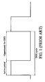
- Fig. 1 shows a schematic diagram of signal transmission in a discontinuous reception mode. A period is sliced into a series of periodic data transmission cycles.
- the base station When the wireless communication system operates in the discontinuous reception mode, the base station only sends control signaling to the user equipment during active periods of the data transmission cycle.
- the user equipment therefore, only needs to receive the control signaling during the active periods, and can enter a sleeping state with low power consumption when not in the active periods.
- the power consumption of the user equipment is therefore reduced to extend the battery life of the user equipment.
- a wireless communication system operating in a semi-persistant scheduling, SPS, mode has similar communication operations with a wireless communication system operating in the discontinuous reception mode.
- a base station operating in a discontinuous reception mode transmits control data to user equipment via a plurality of the component carriers with different frequency bands.
- Each component carrier may have different active periods.
- the base station may send control signaling to the user equipment with three different methods.
- Fig. 2A shows the first schematic diagram of active periods of three component carriers according to an identical configuration method is shown. According to the identical configuration method, the active periods of the three component carriers are the same.
- a base station may send control signaling to the user equipment during the same active periods via the three component carriers. The active periods of the three component carriers therefore have the same configuration.
- DRX with Carrier Aggregation in LTE-Advanced 3GP DRAFT discusses the Rel-10 UE behavior for Discontinuous Reception ,DRX, with carrier aggregation.
- the document discusses the impact of supporting multiple component carriers in relation to battery savings, and proposes that the UE shall perform DRX independently for each component carriers.
- Fig. 2B shows the second schematic diagram of active periods of three component carriers according to an independent configuration method.
- the three component carriers have different active periods and the DRX cycle.
- a base station therefore sends control signaling to the user equipment during different active periods via the three component carriers.
- the base station must send an increased amount of the configuration messages to the user equipment to synchronize transmission and reception of the control signaling.
- Fig. 2C shows the third schematic diagram of active periods of three component carriers according to an anchor carrier based method.
- a carrier is determined as an anchor carrier.
- a base station mainly sends control signaling to the user equipment via the anchor carrier during active periods.
- the base station When the base station uses other component carriers, the base station sends a notification message to the user equipment via the anchor carrier in advance and user equipment receive control signaling on the activated carriers.
- All the aforementioned three methods have shortcomings.
- the user equipment must comprise multiple radio frequency modules to respectively receive radio signals via the multiple component carriers at the same active time periods, and therefore consumes more power.
- the independent configuration method the active periods of the three component carriers are different, and the base station must send extra configuration messages to synchronize transmission and reception of the control signaling.
- the anchor carrier based method only the anchor carrier is used to transmit control signaling and other component carriers are left idle without transmitting control signaling.
- a new method for arranging active periods of different component carriers of a wireless communication system operating in a discontinuous reception mode is therefore required to improve the performance of the wireless communication system.
- the wireless communication system comprises a base station and user equipment, and the base station transmits data to the user equipment via a plurality of the component carriers comprising a series of data transmission cycles.
- the starting time of a plurality of active periods of the component carriers in each data transmission cycle are interleaved in an order, so that the starting time of active periods of the component carriers may not overlap with each other.
- Control data is then sent from the base station to the user equipment via the component carriers during the active periods of the component carriers.
- the control data is then received by the user equipment via the component carriers during the active periods of the component carriers.
- the invention also provides a user equipment.
- the user equipment is wirelessly coupled to a base station via a plurality of component carriers, and comprises a plurality of radio frequency modules and at least one base band processors.
- Each of the plurality of radio frequency modules receives a radio signal from the base station via one of the component carriers during a plurality of active periods of the corresponding component carriers.
- the at least one base band processor retrieves control data from the radio signals received by the radio frequency modules.
- the base station transmits the control data to the user equipment via the component carriers to the user equipment during the active periods of the component carriers, and the starting time of the plurality of active periods of the component carriers are interleaved in each data transmission cycle.
- Fig. 1 is an exemplary schematic diagram of signal transmission in a discontinuous reception mode
- Fig. 2A is an exemplary schematic diagram of active periods of three component carriers according to an identical configuration method
- Fig. 2B is an exemplary schematic diagram of active periods of three component carriers according to an independent configuration method
- Fig. 2C is an exemplary schematic diagram of active periods of three component carriers according to an anchor carrier based method
- Fig. 3 is an exemplary block diagram of a wireless communication system according to the invention.
- Fig. 4A is an exemplary schematic diagram of an embodiment of the arrangement of the active periods of a plurality of the component carriers according to the invention.
- Fig. 4B is an exemplary schematic diagram of another embodiment of the arrangement of the active periods of a plurality of the component carriers according to the invention.
- Fig. 5A is an exemplary block diagram of an embodiment of user equipment with a simplified hardware structure according to the invention.
- Fig. 5B is an exemplary block diagram of another embodiment of user equipment according to the invention.
- Fig. 6A shows an exemplary independent coupling mode coupling radio frequency modules to base band processors according to the invention
- Fig. 6B shows an xemplary combined coupling mode coupling radio frequency modules to base band processors according to the invention
- Fig. 6C shows an exemplary hybrid coupling mode coupling radio frequency modules to base band processors according to the invention
- Fig. 7 is an exemplary schematic diagram of the extension of active periods of the component carriers according to an extension signal
- Fig. 8 is an exemplary schematic diagram of the adjustment of the active periods of the component carriers according to an activation signal.
- Fig. 9 is an exemplary schematic diagram of the suspension of active periods of the component carriers according to an early suspension signal.
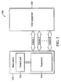
- Fig. 3 shows an exemplary block diagram of a wireless communication system 300 according to the invention is shown.
- the wireless communication system 300 comprises a base station 310 and user equipment 320.
- the base station 310 can be wirelessly coupled to the user equipment 320 via a plurality of the component carriers 1 ⁇ K with different frequency carriers, and data is communicated between the base station 310 and the user equipment via the component carriers 1 ⁇ K.
- the base station 310 also sends control data to the user equipment 320 via the component carriers 1 ⁇ K to negotiate communication requirements and synchronize communication behavior with the user equipment 320.
- the base station 310 sends the control data to the user equipment 320 in a discontinuous reception, DRX mode, as shown in Fig. 1 .
- the base station 310 sends the control data to the user equipment in a semi-persistent scheduling, SPS, mode.
- a staggered configuration method for sending control data from the base station 310 to the user equipment 320 is provided.
- a total time period for data transmission between the base station 310 and the user equipment 320 is divided into a series of data transmission cycles with the same duration.
- each of the component carriers has corresponding active periods in which the base station 310 transmits control data to the user equipment 320 via the corresponding component carrier, and the starting time of an active period of one component carrier is staggered to the starting time of active periods of other component carriers.
- the base station 310 may send control data via one component carrier at a time
- the user equipment 320 receives the control data via one component carrier at a time.
- the staggered method provides diversity in the design of the spatial and frequency domains with simple configuration.
- the base station 310 comprises a control unit 312 and a transceiver 314.
- the control unit 312 interleaves a plurality of the starting time of active periods of the component carriers 1 ⁇ K in each data transmission cycle in an order, so that the starting time of active periods of the component carriers 1 ⁇ K are staggered.
- the transceiver 314 then sends control data to the user equipment 320 via the component carriers 1 ⁇ K during the active periods of the component carriers.
- the user equipment 320 receives the control data via the component carriers 1 ⁇ K during the active periods of the component carriers 1 ⁇ K.
- the user equipment 320 can apply all of its antennas in the reception control data of the active component carrier to improve the signal quality of the control data received via the active component carrier.
- the control unit 312 arranges the active periods of the component carriers 1 ⁇ K in each data transmission cycle in an order, so that the starting time of active periods of the component carriers mutually differ by an offset period.
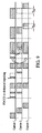
- Fig. 4A an exemplary schematic diagram of an embodiment of the arrangement of the active periods of a plurality of the component carriers according to the invention is shown. Assume that there are three component carriers 1 ⁇ 3 for data transmission between the base station 310 and the user equipment 320. The frequency band of the component carrier 2 is higher than that of the component carrier 1, and the frequency band of the component carrier 3 is higher than that of the component carrier 2. The active period of the component carrier 2 is later than that of the component carrier 1, and the active period of the component carrier 3 is later than that of the component carrier 2. In other words, the active periods of the component carriers having lower frequency bands are earlier than the active periods of the component carriers having higher frequency bands.
- FIG. 4B an exemplary schematic diagram of another embodiment of the arrangement of the active periods of a plurality of the component carriers according to the invention is shown.
- the frequency band of the component carrier 2 is higher than that of the component carrier 1
- the frequency band of the component carrier 3 is higher than that of the component carrier 2.
- the active period of the component carrier 2 is earlier than that of the component carrier 1, and the active period of the component carrier 3 is earlier than that of the component carrier 2.
- the active periods of the component carriers having higher frequency bands are earlier than the active periods of the component carriers having lower frequency bands.
- the user equipment 500 comprises an antenna 502, a radio frequency module 504, and a base band processor 506.
- the user equipment 500 may comprise only one antenna 502, one radio frequency module 504, and one base band processor 506.
- the antenna 502 and the radio frequency module 504 receive a radio signal from the active component carrier during the active period corresponding to the active component carrier.
- the base band processor 506 retrieves control data from the radio signal received by the radio frequency module 504.
- the base band processor 506 sends a control signal CTRL to the radio frequency module to adjust a receiving frequency band to that of the active component carrier.
- Fig. 5A an exemplary block diagram of another embodiment of user equipment 550 according to the invention is shown.
- the user equipment comprises three antennas 512, 522, and 532, three radio frequency modules 514, 524, and 534, three base band processors 516, 526, and 536, and a dynamic switch module 540.
- Each of the antennas 512, 522, and 532 and the corresponding radio frequency modules 514, 524, and 534 receives a radio signal from a base station via one of three component carriers.
- a digital processing circuit comprising the base band processors 516, 526, and 536 then controls the dynamic switch module 540 to selectively couple the output terminals of the radio frequency modules 514, 524, and 534 with input terminals of the base band processors 516, 526, and 536; thereby dynamically sending the radio signals received by the radio frequency modules 514, 524, and 534 to the base band processors 516, 526, and 536.
- the base band processors 516, 526, and 536 then retrieve control data from the radio signals.
- FIG. 6A an exemplary independent coupling mode coupling radio frequency modules to base band processors according to the invention is shown.
- the output terminals of the radio frequency modules RF 1 , RF 2 , and RF 3 are respectively coupled to the input terminals of the base band processors BB 1 , BB 2 , and BB 3 , and the radio signals transmitted via three different component carriers are respectively processed by the base band processors BB 1 , BB 2 , and BB 3 .
- one base band processor can process the functions of these the three processors on different time.
- FIG. 6B an exemplary combined coupling mode coupling radio frequency modules to base band processors according to the invention is shown.
- the output terminals of the radio frequency modules RF 1 , RF 2 , and RF 3 receive signal at the same carrier and are all coupled to the input terminal of the base band processor BB 1 , and the radio signals transmitted the same component carriers are all processed by the base band processor BB 1 .
- one base band processor can process the functions of the base band processor BB 1 .
- FIG. 6C an exemplary hybrid coupling mode coupling radio frequency modules to base band processors according to the invention is shown.
- the output terminal of the radio frequency module RF 1 is coupled to the input terminal of the base band processors BB 1 , and the output terminals of the radio frequency modules RF 2 and RF 3 are both coupled to the input terminal of the base band processor BB 2 , where the RF 2 and RF 3 receive the signals at the same carrier.
- the radio signals transmitted via a first component carrier is processed by the base band processor BB 1
- the radio signals transmitted via a second and a third component carriers are processed by the base band processor BB 2 .
- one base band processor can process the functions of the base band processors BB 1 and BB 2 .
- the base station may sometimes simultaneously activate all component carriers to transmit control data to the user equipment. Because the user equipment still receives control data according to the predetermined active periods of the corresponding component carriers, the base station must inform the user equipment of the adjustment of the active periods of the component carriers. In one embodiment, the base station sends an extension signal to the user equipment to dynamically extend active periods of the component carriers. Referring to Fig. 7 , an exemplary schematic diagram of the extension of active periods of the component carriers according to an extension signal is shown. In a first data transmission cycle, an active period of a component carrier 1 is earlier than the active periods of the component carriers 2 and 3. In a second data transmission cycle, an extension signal is transmitted from the base station to the user equipment.
- the starting time of the active period of the component carrier 1 is therefore delayed from time t 71 to time t 73 , and the starting time of the active period of the component carrier 2 is also delayed from time t 72 to time t 73 .
- the extension signal may be a layer-1 physical dedicated control channel ,PDCCH, signal, a layer-1 physical HARQ indicator channel ,PHICH, signal, a layer-2 MAC control signal, or a layer-3 radio resource control ,RRC, signal.
- the base station sends an activation signal to the user equipment via an early activated component carrier to configure the active periods of at least one later-activated component carrier in some of the data transmission cycles, wherein the active period of the early activated component carrier is earlier than that of the later-activated component carrier.
- Fig. 8 an exemplary schematic diagram of the adjustment of the active periods of the component carriers according to an activation signal is shown. In a first data transmission cycle, an active period of a component carrier 1 is earlier than the active periods of the component carriers 2, 3, and 4.
- an activation signal is transmitted from the base station to the user equipment via the early-activated component carrier 1, and the activation signal comprises information concerning adjustment of the configuration of the active periods of the later-activated component carriers 2, 3, and 4. The starting time of the active periods of the component carriers 2, 3, and 4 are therefore advanced to time t 81 .
- an activation signal is transmitted from the base station to the user equipment via the early-activated component carrier 1, and the activation signal comprises information concerning of adjustment of the configuration of the active periods of the later-activated component carriers 3 and 4. The starting time of the active periods of the component carriers 3 and 4 are therefore advanced to time t 82 .
- the activation signal may also be a layer-1 physical dedicated control channel ,PDCCH, signal, a layer-1 physical HARQ indicator channel ,PHICH, signal, a layer-2 MAC control signal, or a layer-3 radio resource control ,RRC, signal.
- PDCCH layer-1 physical dedicated control channel
- PHICH layer-1 physical HARQ indicator channel
- RRC layer-3 radio resource control
- the base station does not send control data to the user equipment via component carriers.
- the user equipment still tries to receive control data via the component carriers during corresponding active periods, leading to meaningless power consumption.
- the base station may send an early suspension signal to the user equipment to prevent the user equipment from receiving the control data during predetermined active periods of some of the component carriers.
- Fig. 9 a schematic diagram of the suspension of active periods of the component carriers according to an early suspension signal is shown. In a first data transmission cycle, an active period of a component carrier 1 is earlier than the active periods of the component carriers 2 and 3.
- extension signals are transmitted from the base station to the user equipment to align the starting time of the active periods of the component carriers 1 and 2 with that of the active period of the component carrier 3.
- an activation signal is transmitted from the base station to the user equipment via the early-activated component carrier 1, the active period of the later-activated component carriers 2 is therefore delayed, and the active period of the later-activated component carriers 3 is therefore advanced.
- a first early suspension signal is transmitted from the base station to the user equipment, and a first half of the active period of the component carrier 3 is suspended according to the first early suspension signal.
- a second early suspension signal is transmitted from the base station to the user equipment, and the active period of the component carrier 2 is suspended according to the second early suspension signal.
- the early suspension signal is a layer-1 physical dedicated control channel ,PDCCH, signal, a layer-1 physical HARQ indicator channel ,PHICH, signal, a layer-2 MAC control signal, or a layer-3 radio resource control ,RRC, signal.
Landscapes
- Engineering & Computer Science (AREA)
- Signal Processing (AREA)
- Computer Networks & Wireless Communication (AREA)
- Mobile Radio Communication Systems (AREA)
Claims (20)
- Une méthode de communication de données pour un système de communication sans fil, dans laquelle le système de communication sans file comporte une station de base et un équipement utilisateur, la station de base transmettant à l'équipement utilisateur via plusieurs porteuses composantes comprenant une série de cycles de transmission de données, et la méthode comportant:l'entrelacement des temps de démarrage de plusieurs périodes actives des porteuses composantes dans chacun des cycles de transmission de données, dans laquelle les temps de démarrage des périodes actives sont entrelacés suivant un ordre de façon à ce que le temps de démarrage des périodes des porteuses composantes ne se recouvrent pas les uns avec les autres; etla transmission de données de commande depuis la station de base vers l'équipement utilisateur au moyen des composantes de porteuse durant les périodes actives des porteuses composantes.
- La méthode de communication de données telle que revendiquée dans la revendication 1, dans laquelle la méthode de communication de données comporte en outre:la réception de données de commande par l'équipement utilisateur via des porteuses de composante durant les période actives des porteuses composantes.
- La méthode de communication de données telle que revendiquée dans la revendication 1, dans laquelle la station de base transmet les données de commande à l'équipement utilisateur suivant un mode de réception discontinue, DRX, ou suivant un mode semi-persistent, SPS.
- La méthode de communication de données telle que revendiquée dans la revendication 1, dans laquelle les porteuses composantes présentent des bandes de fréquences différentes, et l'étape d'entrelacement comporte:la disposition de périodes actives des porteuses composantes dans chaque cycle de transmission de données suivant un ordre, de telle manière que les périodes actives des porteuses composantes diffèrent l'une de l'autre par une période de décalage.
- La méthode de communication de données telle que revendiquée dans la revendication 4, dans laquelle les périodes actives des porteuses composantes présentant des bandes de fréquence plus élevées interviennent plus tôt ou plus tard que les périodes actives des porteuses composantes ayant les bandes de fréquences plus basses.
- La méthode de communication de données telle que revendiquée dans la revendication 2, dans laquelle:l'équipement utilisateur comporte un module radio-fréquence et un processeur en bande de base, dans lequel le processeur en bande de base sélectionne une porteuse composante active à partir de plusieurs porteuses composantes, le module radio-fréquence recevant un signal radio de la station de base via une porteuse composante active, et le processeur en bande de base extrayant les données de commande du signal radio;l'équipement utilisateur comporte plusieurs modules radio-fréquences et plusieurs processeurs en bande de base, dans lequel chacun des modules radio-fréquences reçoit un signal radio de la station de base via une des porteuses composantes, et chacun des processeurs en bande de base extrait les données de commande des signaux radios;l'équipement utilisateur comporte plusieurs modules radio-fréquences et un processeur en bande de base, dans lequel chacun des modules radio-fréquences reçoit un signal radio de la station de base via une des porteuses composantes, et le processeur en bande de base extrait les données de commande des signaux radios; oul'équipement utilisateur comporte plusieurs modules radio-fréquences, un module de commutation dynamique, et plusieurs processeurs en bande de base, dans lequel chacun des modules radio-fréquences reçoit un signal radio de la station de base via une des porteuses composantes, les commutateurs couplant de manière sélective les modules radio-fréquences aux processeurs en bande de base pour transmettre les signaux radios aux processeurs en bande de base, et les processeurs en bande de base extrayant les données de commande des signaux radios.
- La méthode de communication de données telle que revendiquée dans la revendication 2, dans laquelle l'équipement utilisateur comporte plusieurs modules radio-fréquences et plusieurs processeurs en bande de base, dans laquelle chacun des modules radio-fréquences reçoit un signal radio de la station de base via une des porteuses composantes, et chacun des processeurs en bande de base extrait les données de commande de l'un des signaux radios.
- La méthode de communication de données telle que revendiquée dans la revendication 2, dans laquelle l'équipement utilisateur comporte plusieurs modules radio-fréquences et une processeur en bande de base, dans laquelle chacun des modules radio-fréquences reçoit un signal radio de la station de base via la même porteuse composante, et le processeur en bande de base extrait les données de commande des signaux radios.
- La méthode de communication de données telle que revendiquée dans la revendication 2, dans laquelle l'équipement utilisateur comporte plusieurs modules radio-fréquences, plusieurs commutateurs, et plusieurs processeurs en bande de base, dans laquelle chacun des modules radio-fréquence reçoit un signal radio de la station de base via l'une des porteuses composantes, les commutateurs couplant de manière sélective les modules radio-fréquences aux processeurs en bande de base pour envoyer les signaux radios aux processeurs en bande de base, et les processeurs en bande de base extrayant les données de commande des signaux radios.
- La méthode de communication de données telle que revendiquée dans la revendication 1, dans laquelle la méthode de communication de données comporte en outre:l'envoi d'un signal d'extension depuis la station de base vers l'équipement utilisateur pou étendre les périodes actives de certaines porteuses composantes, de manière à aligner les périodes actives de toutes les porteuses composantes dans certains cycles de transmission de données;dans laquelle le signal d'extension est un signal, PDCCH, de canal de commande dédié physique de couche 1, un signal ,PHICH, de canal d'indicateur HARQ physique de couche 1, un signal de commande MAC de couche 2, ou un signal ,RRC, de commande de ressources radios de couche 3.
- La méthode de communication de données telle que revendiquée dans la revendication 1, dans laquelle la méthode de communication comporte en outre:l'envoi d'un signal d'activation depuis la station de base vers l'équipement utilisateur via une porteuse composante précocement activée pour configurer les périodes actives d'au moins une porteuse composante tardivement activée dans certains cycles de transmission de données, dans laquelle la période active de la porteuse composante précocement activée est plus tôt que celle de la porteuse composante tardivement activée;dans laquelle le signal d'activation est un signal , PDCCH, de canal de commande dédié physique de couche 1, un signal ,PHICH, de canal d'indicateur HARQ physique de couche 1, un signal de commande MAC de couche 2, ou un signal ,RRC, de commande de ressources radios de couche 3.
- La méthode de communication de données telle que revendiquée dans la revendication 1, dans laquelle la méthode de communication comporte en outre:l'envoi de la station de base vers l'équipement utilisateur d'un signal de suspension précoce pour empêcher la réception par l'équipement utilisateur de données de commande dans les périodes actives de certaines porteuses composante dans certains cycles de transmission de données;dans laquelle le signal de suspension précoce est un signal, PDCCH, de canal de commande dédié physique de couche 1, un signal ,PHICH, de canal d'indicateur HARQ physique de couche 1, un signal de commande MAC de couche 2, ou un signal ,RRC, de commande de ressources radios de couche 3.
- Un équipement utilisateur (320, 500), couplée par une liaison sans fil à une station de base (310) via plusieurs porteuses composantes, comprenant:plusieurs modules radio-fréquences (504), configurés chacun pour la réception d'un signal radio de la station de base via une des porteuses composantes durant plusieurs périodes actives des porteuses composantes correspondantes; etau moins un processeur(s) en base de base (506), couplé aux modules radio-fréquences, configuré pour extraire des données de commande des signaux radios reçus par les modules de radio-fréquence;dans lequel les données de commande sont reçues via les porteuses composantes vers l'équipement utilisateur durant les périodes actives des porteuses composantes, et les temps de démarrage des périodes actives des porteuses composantes sont entrelacés dans chacun des cycles de transmission de données,dans lequel les temps de démarrage des périodes actives sont entrelacées suivant un ordre tel que le temps de démarrage des périodes actives des porteuses composantes ne se recouvrent pas l'une à l'autre.
- L'équipement utilisateur tel que revendiqué dans la revendication 13, dans lequel l'équipement utilisateur est configuré pour la réception de données de commande de la station de base suivant un mode de réception discontinue, DRX, ou suivant un mode semi-persistent, SPS.
- L'équipement utilisateur tel que revendiqué dans la revendication 13, dans lequel le processeur en bande de base est configuré pour sélectionner une porteuse composante active à partir de plusieurs porteuses composantes, et configuré pour extraire des données de commande à partir d'un signal radio correspondant à la porteuse composante active.
- L'équipement utilisateur tel que revendiqué dans la revendication 13, dans lequel le processeur en bande de base au moins comporte plusieurs processeurs en bande de base, et les processeurs en bande de base sont respectivement couplés à l'un des processeurs en bande de base et respectivement configurés pour extraire des données de commande de l'un des signaux radios.
- L'équipement utilisateur tel que revendiqué dans la revendication 13, dans lequel le processeur en bande de base au moins comporte plusieurs processeurs en bande de base, et l'équipement utilisateur comporte:plusieurs commutateurs, couplant sélectivement les modules radio-fréquences aux processeurs en bande de base pour l'envoi de signaux radio aux processeurs en bande de base;dans lequel les processeurs en bande de base sont configurés pour extraire les données de commande des signaux radios reçus via les commutateurs.
- L'équipement utilisateur tel que revendiqué dans la revendication 13, configuré pour la réception d'un signal d'extension transmis en outre par la station de base
vers l'équipement utilisateur pour l'extension des périodes actives de certaines porteuses composantes, alignant ainsi les périodes actives de toutes les porteuses composantes durant certains cycles de transmission de données, dans lequel le signal d'extension est un signal, PDCCH, de canal de commande dédié physique de couche 1, un signal ,PHIGH, de canal d'indicateur HARQ physique de couche 1, un signal de commande MAC de couche 2, ou un signal ,RRC, de commande de ressources radios de couche 3. - L'équipement utilisateur tel que revendiqué dans la revendication 13, configuré pour la réception en outre d'un signal d'activation transmis par la station de base à l'équipement utilisateur via une porteuse composante précocement activée pour la configuration des périodes actives d'au moins une porteuse composante tardivement activée dans certains cycles de transmission de données, dans lequel la période active de la porteuse composante précocement activée intervient plus tôt que celle de la porteuse composante tardivement activée, dans lequel le signal d'activation est un signal , PDCCH, de canal de commande dédié physique de couche 1, un signal ,PHICH, de canal d'indicateur HARQ physique de couche 1, un signal de commande MAC de couche 2, ou un signal ,RRC, de commande de ressources radios de couche 3.
- L'équipement utilisateur tel que revendiqué dans la revendication 16, configuré pour la réception en outre d'un signal de suspension transmis par la station de base à l'équipement utilisateur pour empêcher la réception par l'équipement utilisateur de données de commande durant les périodes actives de certaines porteuses composantes dans certains cycles de transmission de données, dans lequel le signal de signal de suspension précoce est un signal, PDCCH, de canal de commande dédié physique de couche 1, un signal ,PHICH, de canal d'indicateur HARQ physique de couche 1, un signal de commande MAC de couche 2, ou un signal ,RRC, de commande de ressources radios de couche 3.
Applications Claiming Priority (1)
| Application Number | Priority Date | Filing Date | Title |
|---|---|---|---|
| US21822909P | 2009-06-18 | 2009-06-18 |
Publications (2)
| Publication Number | Publication Date |
|---|---|
| EP2265059A1 EP2265059A1 (fr) | 2010-12-22 |
| EP2265059B1 true EP2265059B1 (fr) | 2012-12-05 |
Family
ID=42676904
Family Applications (1)
| Application Number | Title | Priority Date | Filing Date |
|---|---|---|---|
| EP10166164A Active EP2265059B1 (fr) | 2009-06-18 | 2010-06-16 | Transmission décalée de réception discontinue pour aggrégation de porteuses |
Country Status (4)
| Country | Link |
|---|---|
| US (1) | US8830978B2 (fr) |
| EP (1) | EP2265059B1 (fr) |
| CN (1) | CN102014091B (fr) |
| TW (1) | TWI423706B (fr) |
Families Citing this family (9)
| Publication number | Priority date | Publication date | Assignee | Title |
|---|---|---|---|---|
| US9462484B2 (en) | 2009-09-30 | 2016-10-04 | Optis Wireless Technology, Llc | Reconfiguration of active component carrier set in multi-carrier wireless systems |
| US8379585B2 (en) * | 2009-10-29 | 2013-02-19 | Lg Electronics Inc. | Method of transmitting semi-persistent scheduling data in multiple component carrier system |
| EP2395797B8 (fr) * | 2010-06-11 | 2014-04-02 | Intel Mobile Communications GmbH | Procédé pour contrôler les modes d'activité de fonctionnement d'un terminal de communication sans fil |
| CN103209487A (zh) * | 2012-01-17 | 2013-07-17 | 中兴通讯股份有限公司 | 一种无线通信方法和通信装置及通信系统 |
| WO2013166311A1 (fr) * | 2012-05-02 | 2013-11-07 | Marvell World Trade Ltd. | Mécanismes de planification pour l'économie d'énergie d'un équipement utilisateur dans un réseau de communication |
| EP2822328B1 (fr) * | 2013-07-04 | 2018-10-03 | Alcatel Lucent | Procédés, appareils et programmes informatiques pour un émetteur/récepteur mobile et pour un émetteur/récepteur de station de base |
| JP6744925B2 (ja) * | 2016-07-21 | 2020-08-19 | テレフオンアクチーボラゲット エルエム エリクソン(パブル) | データチャネルの開始位置のためのフレキシブル指示 |
| US10979182B2 (en) * | 2017-10-30 | 2021-04-13 | Qualcomm Incorporated | Managing hybrid automatic repeat request (HARQ) memory for radio tune-away |
| US20230010588A1 (en) * | 2021-07-07 | 2023-01-12 | Qualcomm Incorporated | Coordinated tune away for multi-sim devices |
Family Cites Families (10)
| Publication number | Priority date | Publication date | Assignee | Title |
|---|---|---|---|---|
| DE102005040027B4 (de) * | 2005-08-23 | 2012-10-25 | Nec Europe Ltd. | Verfahren zur Steuerung der Kommunikation mit mobilen Stationen über ein drahtloses Netzwerk |
| WO2007032649A1 (fr) | 2005-09-15 | 2007-03-22 | Samsung Electronics Co., Ltd. | Methode et appareil pour transmettre et pour recevoir un rapport d'etat comprenant un etat reçu de donnees de paquet dans un systeme de communication mobile |
| JP4786340B2 (ja) | 2005-12-28 | 2011-10-05 | 株式会社エヌ・ティ・ティ・ドコモ | 基地局装置およびパケットスケジューリング方法 |
| JP4869778B2 (ja) | 2006-01-18 | 2012-02-08 | 株式会社エヌ・ティ・ティ・ドコモ | 送信装置、受信装置および通信方法 |
| RU2389159C1 (ru) * | 2006-04-11 | 2010-05-10 | Самсунг Электроникс Ко., Лтд. | Способ и устройство для прерывистого приема пакета в системе мобильной связи |
| JP2007300217A (ja) * | 2006-04-27 | 2007-11-15 | Toshiba Corp | Ofdm信号の送信方法、ofdm送信機及びofdm受信機 |
| JP5001693B2 (ja) * | 2007-03-22 | 2012-08-15 | 株式会社エヌ・ティ・ティ・ドコモ | 移動通信システムで使用される基地局装置及び方法 |
| EP1988649A1 (fr) * | 2007-05-04 | 2008-11-05 | Nokia Siemens Networks Oy | Procédés, systèmes, appareils et produit de programme informatique associé pour l'attribution de ressources de communications |
| CN101483891B (zh) * | 2008-01-08 | 2012-12-05 | 株式会社Ntt都科摩 | 对用户设备设置激活期起始点的方法及装置 |
| WO2009120124A1 (fr) * | 2008-03-25 | 2009-10-01 | Telefonaktiebolaget L M Ericsson (Publ) | Fonctionnalités drx dans des réseaux sans fil à porteuses multiples |
-
2010
- 2010-06-16 EP EP10166164A patent/EP2265059B1/fr active Active
- 2010-06-17 US US12/817,379 patent/US8830978B2/en active Active
- 2010-06-18 CN CN2010102086687A patent/CN102014091B/zh active Active
- 2010-06-18 TW TW099119851A patent/TWI423706B/zh active
Also Published As
| Publication number | Publication date |
|---|---|
| US8830978B2 (en) | 2014-09-09 |
| TWI423706B (zh) | 2014-01-11 |
| CN102014091A (zh) | 2011-04-13 |
| US20110026498A1 (en) | 2011-02-03 |
| EP2265059A1 (fr) | 2010-12-22 |
| CN102014091B (zh) | 2013-08-07 |
| TW201110774A (en) | 2011-03-16 |
Similar Documents
| Publication | Publication Date | Title |
|---|---|---|
| EP2265059B1 (fr) | Transmission décalée de réception discontinue pour aggrégation de porteuses | |
| KR102363747B1 (ko) | 5g new radio에서의 대역폭부, 검색 공간 및 접속 모드 불연속 수신 동작의 공동 최적화 | |
| US8767604B2 (en) | Methods and arrangements in a telecommunication system | |
| EP2959729B1 (fr) | Équipement utilisateur doté de modes de fonctionnement à consommation d'énergie réduite | |
| US12464595B2 (en) | Radio wakeup radio | |
| JP2022177185A (ja) | 基地局、移動局、及び、方法 | |
| US9603091B2 (en) | Reducing periodic reporting in discontinuous receive (DRX) mode | |
| US20110207495A1 (en) | Method and Arrangement in a Multi-Carrier Communication Network System | |
| CN114557049A (zh) | 用于载波聚合的连接非连续接收 | |
| AU2010260186A1 (en) | Method and system for discontinuous reception operation for long term evolution advanced carrier aggregation | |
| US20140355504A1 (en) | Handling a State of a Device | |
| US20240236858A1 (en) | Methods, devices, and systems for transmitting and receiving signal for power management | |
| CN118450470A (zh) | 一种通信方法及装置 | |
| WO2021259343A1 (fr) | Adaptation efficace d'économie d'énergie d'ue dans une nouvelle radio (nr) 5g | |
| CN118383054A (zh) | 无线通信方法、终端设备和网络设备 | |
| EP4319265A1 (fr) | Procédé d'envoi d'informations de commande de liaison descendante (dci) et appareil de communication | |
| CN121080048A (zh) | 与配置的调度会话的激活或禁用有关的装置、方法和计算机程序 | |
| CN121510220A (zh) | 一种免调度传输方法及相关装置 |
Legal Events
| Date | Code | Title | Description |
|---|---|---|---|
| PUAI | Public reference made under article 153(3) epc to a published international application that has entered the european phase |
Free format text: ORIGINAL CODE: 0009012 |
|
| AK | Designated contracting states |
Kind code of ref document: A1 Designated state(s): AL AT BE BG CH CY CZ DE DK EE ES FI FR GB GR HR HU IE IS IT LI LT LU LV MC MK MT NL NO PL PT RO SE SI SK SM TR |
|
| AX | Request for extension of the european patent |
Extension state: BA ME RS |
|
| 17P | Request for examination filed |
Effective date: 20110111 |
|
| 17Q | First examination report despatched |
Effective date: 20110919 |
|
| GRAP | Despatch of communication of intention to grant a patent |
Free format text: ORIGINAL CODE: EPIDOSNIGR1 |
|
| GRAS | Grant fee paid |
Free format text: ORIGINAL CODE: EPIDOSNIGR3 |
|
| GRAA | (expected) grant |
Free format text: ORIGINAL CODE: 0009210 |
|
| AK | Designated contracting states |
Kind code of ref document: B1 Designated state(s): AL AT BE BG CH CY CZ DE DK EE ES FI FR GB GR HR HU IE IS IT LI LT LU LV MC MK MT NL NO PL PT RO SE SI SK SM TR |
|
| REG | Reference to a national code |
Ref country code: GB Ref legal event code: FG4D |
|
| REG | Reference to a national code |
Ref country code: CH Ref legal event code: EP |
|
| REG | Reference to a national code |
Ref country code: AT Ref legal event code: REF Ref document number: 587863 Country of ref document: AT Kind code of ref document: T Effective date: 20121215 |
|
| REG | Reference to a national code |
Ref country code: IE Ref legal event code: FG4D |
|
| REG | Reference to a national code |
Ref country code: DE Ref legal event code: R096 Ref document number: 602010003926 Country of ref document: DE Effective date: 20130131 |
|
| REG | Reference to a national code |
Ref country code: AT Ref legal event code: MK05 Ref document number: 587863 Country of ref document: AT Kind code of ref document: T Effective date: 20121205 |
|
| REG | Reference to a national code |
Ref country code: NL Ref legal event code: T3 |
|
| PG25 | Lapsed in a contracting state [announced via postgrant information from national office to epo] |
Ref country code: ES Free format text: LAPSE BECAUSE OF FAILURE TO SUBMIT A TRANSLATION OF THE DESCRIPTION OR TO PAY THE FEE WITHIN THE PRESCRIBED TIME-LIMIT Effective date: 20130316 Ref country code: FI Free format text: LAPSE BECAUSE OF FAILURE TO SUBMIT A TRANSLATION OF THE DESCRIPTION OR TO PAY THE FEE WITHIN THE PRESCRIBED TIME-LIMIT Effective date: 20121205 Ref country code: LT Free format text: LAPSE BECAUSE OF FAILURE TO SUBMIT A TRANSLATION OF THE DESCRIPTION OR TO PAY THE FEE WITHIN THE PRESCRIBED TIME-LIMIT Effective date: 20121205 Ref country code: SE Free format text: LAPSE BECAUSE OF FAILURE TO SUBMIT A TRANSLATION OF THE DESCRIPTION OR TO PAY THE FEE WITHIN THE PRESCRIBED TIME-LIMIT Effective date: 20121205 Ref country code: NO Free format text: LAPSE BECAUSE OF FAILURE TO SUBMIT A TRANSLATION OF THE DESCRIPTION OR TO PAY THE FEE WITHIN THE PRESCRIBED TIME-LIMIT Effective date: 20130305 |
|
| REG | Reference to a national code |
Ref country code: LT Ref legal event code: MG4D |
|
| PG25 | Lapsed in a contracting state [announced via postgrant information from national office to epo] |
Ref country code: GR Free format text: LAPSE BECAUSE OF FAILURE TO SUBMIT A TRANSLATION OF THE DESCRIPTION OR TO PAY THE FEE WITHIN THE PRESCRIBED TIME-LIMIT Effective date: 20130306 Ref country code: SI Free format text: LAPSE BECAUSE OF FAILURE TO SUBMIT A TRANSLATION OF THE DESCRIPTION OR TO PAY THE FEE WITHIN THE PRESCRIBED TIME-LIMIT Effective date: 20121205 Ref country code: LV Free format text: LAPSE BECAUSE OF FAILURE TO SUBMIT A TRANSLATION OF THE DESCRIPTION OR TO PAY THE FEE WITHIN THE PRESCRIBED TIME-LIMIT Effective date: 20121205 Ref country code: PL Free format text: LAPSE BECAUSE OF FAILURE TO SUBMIT A TRANSLATION OF THE DESCRIPTION OR TO PAY THE FEE WITHIN THE PRESCRIBED TIME-LIMIT Effective date: 20121205 |
|
| PG25 | Lapsed in a contracting state [announced via postgrant information from national office to epo] |
Ref country code: AT Free format text: LAPSE BECAUSE OF FAILURE TO SUBMIT A TRANSLATION OF THE DESCRIPTION OR TO PAY THE FEE WITHIN THE PRESCRIBED TIME-LIMIT Effective date: 20121205 |
|
| PG25 | Lapsed in a contracting state [announced via postgrant information from national office to epo] |
Ref country code: IS Free format text: LAPSE BECAUSE OF FAILURE TO SUBMIT A TRANSLATION OF THE DESCRIPTION OR TO PAY THE FEE WITHIN THE PRESCRIBED TIME-LIMIT Effective date: 20130405 Ref country code: BG Free format text: LAPSE BECAUSE OF FAILURE TO SUBMIT A TRANSLATION OF THE DESCRIPTION OR TO PAY THE FEE WITHIN THE PRESCRIBED TIME-LIMIT Effective date: 20130305 Ref country code: EE Free format text: LAPSE BECAUSE OF FAILURE TO SUBMIT A TRANSLATION OF THE DESCRIPTION OR TO PAY THE FEE WITHIN THE PRESCRIBED TIME-LIMIT Effective date: 20121205 Ref country code: CZ Free format text: LAPSE BECAUSE OF FAILURE TO SUBMIT A TRANSLATION OF THE DESCRIPTION OR TO PAY THE FEE WITHIN THE PRESCRIBED TIME-LIMIT Effective date: 20121205 Ref country code: SK Free format text: LAPSE BECAUSE OF FAILURE TO SUBMIT A TRANSLATION OF THE DESCRIPTION OR TO PAY THE FEE WITHIN THE PRESCRIBED TIME-LIMIT Effective date: 20121205 Ref country code: BE Free format text: LAPSE BECAUSE OF FAILURE TO SUBMIT A TRANSLATION OF THE DESCRIPTION OR TO PAY THE FEE WITHIN THE PRESCRIBED TIME-LIMIT Effective date: 20121205 |
|
| PG25 | Lapsed in a contracting state [announced via postgrant information from national office to epo] |
Ref country code: RO Free format text: LAPSE BECAUSE OF FAILURE TO SUBMIT A TRANSLATION OF THE DESCRIPTION OR TO PAY THE FEE WITHIN THE PRESCRIBED TIME-LIMIT Effective date: 20121205 Ref country code: PT Free format text: LAPSE BECAUSE OF FAILURE TO SUBMIT A TRANSLATION OF THE DESCRIPTION OR TO PAY THE FEE WITHIN THE PRESCRIBED TIME-LIMIT Effective date: 20130405 |
|
| PLBE | No opposition filed within time limit |
Free format text: ORIGINAL CODE: 0009261 |
|
| STAA | Information on the status of an ep patent application or granted ep patent |
Free format text: STATUS: NO OPPOSITION FILED WITHIN TIME LIMIT |
|
| PG25 | Lapsed in a contracting state [announced via postgrant information from national office to epo] |
Ref country code: DK Free format text: LAPSE BECAUSE OF FAILURE TO SUBMIT A TRANSLATION OF THE DESCRIPTION OR TO PAY THE FEE WITHIN THE PRESCRIBED TIME-LIMIT Effective date: 20121205 |
|
| 26N | No opposition filed |
Effective date: 20130906 |
|
| PG25 | Lapsed in a contracting state [announced via postgrant information from national office to epo] |
Ref country code: CY Free format text: LAPSE BECAUSE OF FAILURE TO SUBMIT A TRANSLATION OF THE DESCRIPTION OR TO PAY THE FEE WITHIN THE PRESCRIBED TIME-LIMIT Effective date: 20121205 |
|
| PG25 | Lapsed in a contracting state [announced via postgrant information from national office to epo] |
Ref country code: IT Free format text: LAPSE BECAUSE OF FAILURE TO SUBMIT A TRANSLATION OF THE DESCRIPTION OR TO PAY THE FEE WITHIN THE PRESCRIBED TIME-LIMIT Effective date: 20121205 |
|
| REG | Reference to a national code |
Ref country code: DE Ref legal event code: R097 Ref document number: 602010003926 Country of ref document: DE Effective date: 20130906 |
|
| PG25 | Lapsed in a contracting state [announced via postgrant information from national office to epo] |
Ref country code: HR Free format text: LAPSE BECAUSE OF FAILURE TO SUBMIT A TRANSLATION OF THE DESCRIPTION OR TO PAY THE FEE WITHIN THE PRESCRIBED TIME-LIMIT Effective date: 20130731 Ref country code: MC Free format text: LAPSE BECAUSE OF FAILURE TO SUBMIT A TRANSLATION OF THE DESCRIPTION OR TO PAY THE FEE WITHIN THE PRESCRIBED TIME-LIMIT Effective date: 20121205 |
|
| REG | Reference to a national code |
Ref country code: IE Ref legal event code: MM4A |
|
| PG25 | Lapsed in a contracting state [announced via postgrant information from national office to epo] |
Ref country code: IE Free format text: LAPSE BECAUSE OF NON-PAYMENT OF DUE FEES Effective date: 20130616 |
|
| REG | Reference to a national code |
Ref country code: CH Ref legal event code: PL |
|
| PG25 | Lapsed in a contracting state [announced via postgrant information from national office to epo] |
Ref country code: MT Free format text: LAPSE BECAUSE OF FAILURE TO SUBMIT A TRANSLATION OF THE DESCRIPTION OR TO PAY THE FEE WITHIN THE PRESCRIBED TIME-LIMIT Effective date: 20121205 |
|
| PG25 | Lapsed in a contracting state [announced via postgrant information from national office to epo] |
Ref country code: CH Free format text: LAPSE BECAUSE OF NON-PAYMENT OF DUE FEES Effective date: 20140630 Ref country code: LI Free format text: LAPSE BECAUSE OF NON-PAYMENT OF DUE FEES Effective date: 20140630 |
|
| PG25 | Lapsed in a contracting state [announced via postgrant information from national office to epo] |
Ref country code: SM Free format text: LAPSE BECAUSE OF FAILURE TO SUBMIT A TRANSLATION OF THE DESCRIPTION OR TO PAY THE FEE WITHIN THE PRESCRIBED TIME-LIMIT Effective date: 20121205 |
|
| PG25 | Lapsed in a contracting state [announced via postgrant information from national office to epo] |
Ref country code: TR Free format text: LAPSE BECAUSE OF FAILURE TO SUBMIT A TRANSLATION OF THE DESCRIPTION OR TO PAY THE FEE WITHIN THE PRESCRIBED TIME-LIMIT Effective date: 20121205 |
|
| PG25 | Lapsed in a contracting state [announced via postgrant information from national office to epo] |
Ref country code: MK Free format text: LAPSE BECAUSE OF FAILURE TO SUBMIT A TRANSLATION OF THE DESCRIPTION OR TO PAY THE FEE WITHIN THE PRESCRIBED TIME-LIMIT Effective date: 20121205 Ref country code: LU Free format text: LAPSE BECAUSE OF NON-PAYMENT OF DUE FEES Effective date: 20130616 Ref country code: HU Free format text: LAPSE BECAUSE OF FAILURE TO SUBMIT A TRANSLATION OF THE DESCRIPTION OR TO PAY THE FEE WITHIN THE PRESCRIBED TIME-LIMIT; INVALID AB INITIO Effective date: 20100616 |
|
| REG | Reference to a national code |
Ref country code: FR Ref legal event code: PLFP Year of fee payment: 7 |
|
| REG | Reference to a national code |
Ref country code: FR Ref legal event code: PLFP Year of fee payment: 8 |
|
| REG | Reference to a national code |
Ref country code: FR Ref legal event code: PLFP Year of fee payment: 9 |
|
| PG25 | Lapsed in a contracting state [announced via postgrant information from national office to epo] |
Ref country code: AL Free format text: LAPSE BECAUSE OF FAILURE TO SUBMIT A TRANSLATION OF THE DESCRIPTION OR TO PAY THE FEE WITHIN THE PRESCRIBED TIME-LIMIT Effective date: 20121205 |
|
| PGFP | Annual fee paid to national office [announced via postgrant information from national office to epo] |
Ref country code: NL Payment date: 20250421 Year of fee payment: 16 |
|
| PGFP | Annual fee paid to national office [announced via postgrant information from national office to epo] |
Ref country code: DE Payment date: 20250423 Year of fee payment: 16 |
|
| PGFP | Annual fee paid to national office [announced via postgrant information from national office to epo] |
Ref country code: GB Payment date: 20250425 Year of fee payment: 16 |
|
| PGFP | Annual fee paid to national office [announced via postgrant information from national office to epo] |
Ref country code: FR Payment date: 20250422 Year of fee payment: 16 |