EP2265039B1 - Hörgerät - Google Patents
Hörgerät Download PDFInfo
- Publication number
- EP2265039B1 EP2265039B1 EP10738319A EP10738319A EP2265039B1 EP 2265039 B1 EP2265039 B1 EP 2265039B1 EP 10738319 A EP10738319 A EP 10738319A EP 10738319 A EP10738319 A EP 10738319A EP 2265039 B1 EP2265039 B1 EP 2265039B1
- Authority
- EP
- European Patent Office
- Prior art keywords
- adjustment amount
- hearing aid
- signal
- gain
- speech
- Prior art date
- Legal status (The legal status is an assumption and is not a legal conclusion. Google has not performed a legal analysis and makes no representation as to the accuracy of the status listed.)
- Not-in-force
Links
- 230000001629 suppression Effects 0.000 claims abstract description 75
- 230000006835 compression Effects 0.000 claims abstract description 62
- 238000007906 compression Methods 0.000 claims abstract description 62
- 230000003247 decreasing effect Effects 0.000 claims description 20
- 230000007423 decrease Effects 0.000 claims description 10
- 238000001514 detection method Methods 0.000 description 29
- 238000000034 method Methods 0.000 description 23
- 238000004088 simulation Methods 0.000 description 10
- 238000001228 spectrum Methods 0.000 description 10
- 230000003321 amplification Effects 0.000 description 8
- 238000003199 nucleic acid amplification method Methods 0.000 description 8
- 230000006870 function Effects 0.000 description 7
- 230000000694 effects Effects 0.000 description 6
- 230000002238 attenuated effect Effects 0.000 description 5
- 238000010586 diagram Methods 0.000 description 5
- 230000009471 action Effects 0.000 description 3
- 238000004458 analytical method Methods 0.000 description 3
- 230000008859 change Effects 0.000 description 3
- 230000007613 environmental effect Effects 0.000 description 3
- 238000001914 filtration Methods 0.000 description 3
- 230000005236 sound signal Effects 0.000 description 3
- 238000004364 calculation method Methods 0.000 description 2
- 230000009467 reduction Effects 0.000 description 2
- 230000035945 sensitivity Effects 0.000 description 2
- 238000004904 shortening Methods 0.000 description 2
- 238000004378 air conditioning Methods 0.000 description 1
- 230000008901 benefit Effects 0.000 description 1
- 238000006243 chemical reaction Methods 0.000 description 1
- 230000000052 comparative effect Effects 0.000 description 1
- 239000000470 constituent Substances 0.000 description 1
- 230000006866 deterioration Effects 0.000 description 1
- 238000005516 engineering process Methods 0.000 description 1
- 239000002184 metal Substances 0.000 description 1
- 230000004048 modification Effects 0.000 description 1
- 238000012986 modification Methods 0.000 description 1
- 238000003672 processing method Methods 0.000 description 1
- 230000007115 recruitment Effects 0.000 description 1
- 230000004044 response Effects 0.000 description 1
- 230000000630 rising effect Effects 0.000 description 1
Images


Classifications
-
- H—ELECTRICITY
- H04—ELECTRIC COMMUNICATION TECHNIQUE
- H04R—LOUDSPEAKERS, MICROPHONES, GRAMOPHONE PICK-UPS OR LIKE ACOUSTIC ELECTROMECHANICAL TRANSDUCERS; DEAF-AID SETS; PUBLIC ADDRESS SYSTEMS
- H04R25/00—Deaf-aid sets, i.e. electro-acoustic or electro-mechanical hearing aids; Electric tinnitus maskers providing an auditory perception
- H04R25/35—Deaf-aid sets, i.e. electro-acoustic or electro-mechanical hearing aids; Electric tinnitus maskers providing an auditory perception using translation techniques
- H04R25/356—Amplitude, e.g. amplitude shift or compression
Definitions
- the present invention relates to a hearing aid that combines noise suppression processing with nonlinear compression processing.
- a conventional hearing aid comprises an A/D converter for converting analog input signals produced according to input sound into digital input signals, a frequency characteristic processing means for adjusting the frequency characteristics of digital input signals, an amplifier for amplifying digital input signals, a D/A converter for converting digital input signals into analog sound signals and outputting the analog sound signals, a control signal input/ output means for inputting and outputting control signals, and so forth.
- Spectrum subtraction is a noise suppression processing method in which just the noise component is subtracted from a digital input signal by statistical estimation of the noise level of a non-speech segment.
- Directional control is executed using a directional microphone or a plurality of non-directional microphones.
- the SN ratio signal to noise ratio
- the SN ratio can be improved by lowering the sensitivity of the microphone in everything but the forward direction, while leaving the sensitivity unchanged in the forward direction.
- sound from ahead can be emphasized by correcting any offset in the time at which speech was inputted to the plurality of microphones, and adding together the plurality of input signals.
- the present invention was conceived in light of the above situation, and it is an object thereof to provide a hearing aid with which noise suppression processing and nonlinear compression processing are combined so that speech can be clearly heard.
- the hearing aid of the present invention comprises a microphone for producing an input signal from input sound; a noise suppressor for estimating the noise component strength included in the input signal on the basis of the signal strength for each of a plurality of frequency bands in the input signal, and calculating for each of the plurality of frequency bands a noise suppression gain for suppressing the noise component strength, an adjustment amount calculator for calculating an adjustment amount on the basis of the signal strength and the noise component strength, a reference gain information memory for storing specific reference gain information, a nonlinear compressor for calculating a reference gain on the basis of the signal strength and the specific reference gain, and adjusting the reference gain on the basis of the adjustment amount, and thereby calculating for each of the plurality of frequency bands a nonlinear compression gain for nonlinearly compressing and amplifying the input signal, a controller for producing an output signal by controlling the input signal on the basis of the noise suppression gain and the nonlinear compression gain, and a receiver for reproducing an output sound from the output signal.
- the present invention provides a hearing aid with which noise suppression processing and nonlinear compression processing are combined so that speech can be clearly heard.
- noise suppression processing is performed to suppress the noise component included in an input signal, after which nonlinear compression processing (NLC) is performed to amplify the input signal with a different gain (amplification ratio) for each frequency band.
- NLC nonlinear compression processing
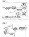
- FIG 1 shows the constitution of the hearing aid pertaining to the first embodiment of the present invention.
- the hearing aid pertaining to this embodiment has a microphone 101 that produces an analog input signal from input sound, a signal processing means 102 for producing an analog output signal by subjecting the analog input signal to specific signal processing, and a receiver 103 that reproduces an output sound from the analog output signal.
- the signal processing means 102 has an A/D converter 121, a frequency analyzer 123, a frequency power calculator 124, a noise suppressor 126, a nonlinear compressor 127, a reference gain information memory 128, an adjustment amount calculator 129, a total gain calculator 130, a controller 131, a frequency synthesizer 132, and a D/A converter 133.
- the A/D converter 121 converts the analog input signal produced by the microphone 101 into a digital input signal processed by the signal processing means 102.
- the digital input signal will hereinafter be referred to simply as an "input signal.”
- the desired signal included in the input signal is a speech signal.
- a speech signal includes a component corresponding to the voice emitted by humans, such as conversation sounds, singing voices, and so forth, and a component corresponding to a human voice that has gone through a machine, such as a voice on the telephone, a television voice, and so forth.
- the frequency analyzer 123 divides the input signal into specific time segments, and converts a time-domain input signal into a frequency-domain input signal. Examples of conversion into frequency-domains include FFT (fast Fourier transform), and sub-band coding.
- FFT fast Fourier transform
- the frequency power calculator 124 calculates the frequency power (signal strength) for each frequency band from the real part and the imaginary part of the frequency-domain input signals. Examples of the method for calculating frequency power include the RMS (root mean square) and a method in which the squares of the real part and the imaginary part are summed, but other methods can be used instead.
- the noise suppressor 126 calculates the signal component strength of the input signal on the basis of the frequency power for each frequency band outputted from the frequency power calculator 124, and estimates the noise component strength included in the input signal.
- the noise suppressor 126 computes a noise suppression gain Gns for suppressing the noise component of the input signal on the basis of the estimated signal component strength and the noise component strength. The noise suppressor 126 will be discussed in further detail below.
- the adjustment amount calculator 129 calculates the adjustment amount used in adjusting the reference gain (discussed below), for each frequency band, on the basis of the noise suppression gain Gns, the noise component strength, and the signal component strength estimated by the noise suppressor 126. The calculated adjustment amount is outputted to the nonlinear compressor 127. The operation of the adjustment amount calculator 129 will be discussed in further detail below.
- the nonlinear compressor 127 determines a nonlinear compression gain Gnlc for each frequency segment on the basis of the frequency power for each frequency band outputted from the frequency power calculator 124, the adjustment amount calculated by the adjustment amount calculator 129, and a reference gain information stored in the reference gain information memory 128. More specifically, the nonlinear compressor 127 computes the reference gain corresponding to the frequency power for each frequency band by referring to reference gain information. The nonlinear compressor 127 then multiplies the reference gain by the adjustment amount to calculate the nonlinear compression gain Gnlc for each frequency band.
- the reference gain information here refers a nonlinear compression function determined according to the-hearing level of the hearing aid user.
- FIG 8 is an example of reference the gain information utilized by the nonlinear compressor 127. With the reference gain derived from the reference gain information, the input signal is amplified or compressed in the direction of ameliorating the decrease in hearing level and the narrowing of the dynamic range (audible range). The reference gain information is stored in the reference gain information memory 128 ahead of time for each frequency segment.
- the nonlinear function and the operation of the nonlinear compressor 127 will be described in detail below.
- the controller 131 amplifies the input signal with the total gain G. More specifically, the controller 131 amplifies the frequency-domain input signals by multiplying the total gain G for each frequency segment by the frequency-domain input signal produced by the frequency analyzer 123. Consequently, the controller 131 produces an output signal.
- the frequency synthesizer 132 synthesizes an output signal for each amplified frequency. More specifically, the frequency synthesizer 132 converts the frequency-domain output signal into a time -domain output signal by IFFT (inverse FFT), for example.
- IFFT inverse FFT
- the D/A converter 133 converts the output signal produced by the signal processing means 102, that is, a digital output signal, into an analog output signal.
- FIG 8 is an example of the nonlinear compression function used by the nonlinear compressor 127, and will be described using FIG. 5 in WO H2-502151 as an example.
- the horizontal axis is Fi, which is the logarithmic amplitude envelope (dB) of the sound pressure level of the input signal
- the vertical axis is Fo, which is- the- logarithmic amplitude envelope (dB) of the output signal.
- the adaptable amplifier When the input signal level exceeds the selected level displayed as K1, the adaptable amplifier imparts linear gain to the input signal.
- the slope R1 of the Fi-Fo curve is preferably about one. Consequently, a gain function that is suited to the hearing level of the individual hearing aid user is selected for an input signal having an amplitude in the normal speech segment.
- the adaptable amplifier reduces the linear portion of the gain curve below one, and thereby compresses the input signal.
- This K2 level is preferably selected so that signals that exceed the MCL (most comfortable level), which is the sound pressure level at which the user feels most comfortable, are compressed. Therefore, the three linear portions of the input/ output curve in FIG 8 act such that weak signals are expanded, ordinary speech signals are amplified as usual, and strong signals are compressed.
- nonlinear compressor 127 With the nonlinear compressor 127, however, compression and expansion are performed according to the level of the input signal, regardless of the SN ratio (the ratio of the signal component strength and noise component strength) or whether a segment is a speech segment or a non-speech segment. Accordingly, noise that is a non-speech signal may end up being expanded, or a speech signal may end up being compressed, for example. Solving this problem is a characteristic feature of the hearing aid pertaining to this embodiment.
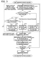
- FIG 2 is a diagram of the constitution of the noise suppressor 126 pertaining to the first embodiment of the present invention.
- the noise suppressor 126 has a band extractor 201, a noise component estimator 202, a nonlinear compression gain calculator 205, and a nonlinear compression gain time constant controller 207.
- the band extractor 201 acquires the frequency power calculated by the frequency power calculator 124 (here, both a speech component and a noise component may be included as the signal component of frequency power).
- the band extractor 201 sets as the signal component strength the results of computation in which the frequency power for every frequency band are compiled for every frequency segment on the basis of the frequency segment for which the noise suppression gain Gns (discussed below) is calculated.
- the frequency segment here is composed of a single frequency band or a plurality of frequency bands.
- the noise component estimator 202 the noise component strength is estimated from the frequency power for every frequency segment.
- An example of a method for estimating the noise component will be described.
- One possible estimation method is to focus on the fact that the frequency power fluctuates in the time axis direction. More specifically, when the frequency power is falling, it is used as the noise component strength, and when the frequency power is rising, the value of the frequency power one unit of time earlier is multiplied by a specific constant (a value slightly greater than one). This estimation method is called "minimum hold."
- the one unit of time may be, for example, the time period during which frequency analysis is performed, or one-half this time period in order to overlap frequency analysis processing, but other units may be used instead.
- the noise suppression gain Gns here satisfies the relation 0 ⁇ Gns ⁇ 1. In this description, we will assume the minimum value of the noise suppression gain Gns to be a value close to zero, but that is not necessarily the case.
- the generation of this odd noise can be reduced by setting the minimum value of the noise suppression gain Gns to a value closer to one than zero.
- the noise suppression gain Gns may be a negative value or less than the minimum value, but in this case the noise suppression gain Gns should be set to the minimum value.
- the nonlinear compression gain time constant controller 207 performs time constant control over the noise suppression gain Gns. When a large amount of signal component such as speech is included in the input signal, the nonlinear compression gain time constant controller 207 shortens the time constant at which the noise suppression gain Gns is controlled in the increasing direction, and lengthens the time constant in which it is controlled in the decreasing direction. This prevents the speech signal included in the input signal from being suppressed by the noise suppressor, and allows for rapid response to setting that goes through the speech component when speech has been resumed after the speech signal is cut off.
- the nonlinear compression gain time constant controller 207 shortens the time constant at which the noise suppression gain Gns is controlled in the decreasing direction, and lengthens the time constant in which it is controlled in the increasing direction. This allows the system to handle sudden noises with large time fluctuations. Also, in a sound environment in which steady noise is dominant, fluctuation in the level of noise suppression gain can be reduced, so it is possible to provide a sound that is easier to hear.
- the noise suppressor 126 may also utilize Wiener filtering, in which suppression processing is performed so that the strength of the noise component is attenuated.
- Wiener filtering When noise is suppressed by Wiener filtering, the Wiener filter is provided to the noise suppressor 126, and the waveform of the filter output is made as similar as possible to the waveform of the filter input that includes no noise component.
- noise suppression is performed by spectrum subtraction, noise suppression is accomplished by subtracting the signal of the non-speech component (that is, the signal of just the noise component)-from an input signal that includes a speech component and a noise component. This allows the signal strength of the noise component to be attenuated.
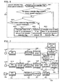
- FIG 3 is a flowchart illustrating an example of the operation of the adjustment amount calculator 129 pertaining to the first embodiment of the present invention.
- the default value of the adjustment amount is set to "1".
- the SN ratio is calculated on the basis of the signal component strength and noise component strength acquired from the noise suppressor 126 (step S301). Then, it is determined whether or not the calculated SN ratio is less than a first threshold (step S302). If the SN ratio is less than the first threshold, a value less than "1" is calculated as the adjustment amount from the SN ratio (step S303). That is, if the SN ratio is lower than the first threshold, processing is performed to reduce the adjustment amount. On the other hand, if the SN ratio in step S302 is at or above the first threshold, it is determined whether or not the SN ratio is less than a second threshold (step S304).
- a value of at least "1" is calculated as the adjustment amount from the SN ratio (step S305). That is, if the SN ratio is higher than the second threshold, processing is performed to increase the adjustment amount. If the SN ratio is at or above the first threshold and less than the second threshold, the value "1" is substituted as the adjustment amount. That is, the adjustment amount is not increased or decreased.
- the first threshold shall be no higher than the second threshold.
- the noise suppression gain Gns is acquired from the noise suppressor 126 (step S307). Then, the maximum and minimum values for the adjustment amount are set on the basis of the noise suppression gain Gns (step S308). The adjustment amount is then subjected to time constant control (step S309). It is then determined whether or not the processing of steps S301 to S309 has ended for all the frequency segments (all bands) (step S310). If it has not ended for all frequency segments, the flow returns to step S301 to perform processing on any unprocessed frequency segments. If the processing has ended for all the frequency segments, the adjustment amount is outputted to the nonlinear compressor 127 (step S311).
- the maximum value may also be set in step S305.
- An example of a method for setting the minimum value of the adjustment amount is a method in which the value at which the product of the adjustment amounts and the noise suppression gains Gns calculated for every specified time segment is at its minimum is set to be the minimum value of the adjustment amount. To put this another way, the value obtained by dividing the minimum value of the noise suppression gain Gns by the noise suppression gain Gns is used as the minimum value for the adjustment amount. The purpose of performing this setting is to match the minimum value of the adjustment amount to the maximum suppression amount possible with noise suppression processing.
- An example of a method for setting the maximum value for the adjustment amount is a method in which the value of the adjustment amount when the product of the adjustment amount and the noise suppression gain Gns for a certain frequency segment is 1 is set to be the maximum value for the adjustment amount.
- the inverse of the noise suppression gain Gns calculated for every specific time segment is set to be the maximum value for the adjustment amount.
- the purpose of performing this setting is that, when a specific time segment in which a speech signal is included is taken into account in noise suppression processing, a speech signal that has been suppressed by noise suppression processing can be restored to the amplification level of the input signal.
- the maximum and minimum values for the adjustment amount may be set without using the noise suppression gain Gns.
- the maximum and minimum values for the adjustment amount may be set to specific default values. In this case, there is no need for comparative computation of the adjustment amount by frequency band, so the power consumption of the hearing aid can be reduced.
- steps S302 and S304 two thresholds for comparing the SN ratio are readied, so that the step of setting the adjustment amount is classified into three steps, namely, a step of setting to a value of at least 1, a step of setting to 1, and a step of setting to a value less than 1, but this is not necessarily the case.
- just one threshold may be readied, so that the step of setting the adjustment amount is classified into two steps.
- the adjustment amount when the SN ratio is at or above the threshold, the adjustment amount may be set to 1 or more, and when the SN ratio is less than the threshold, the adjustment amount may be set to less than 1.
- the first and second thresholds may be set so that the loudness levels for the various frequency bands are constant. Doing this makes it possible to clearly hear speech, according to the sense of the hearing aid user.
- the loudness level is a numerical value that corresponds to a curve group produced by using 1000 Hz pure sound as a reference in 10dB units, and -finding the sound pressure level for pure sound of another frequency that sounds equally loud as sound of that sound pressure level.
- the unit of loudness is the phon.
- the first threshold and second threshold may each be set to a different value for every frequency band.
- the first and second thresholds can be determined on the basis of a comparison between the frequency characteristics of typical speech and the frequency characteristics of steady noise (such as traffic noise or crowd noise).
- the frequency characteristics of speech have a tendency for the power spectrum to be concentrated in a low frequency band of approximately 800 Hz or less.
- the frequency characteristics of traffic noise has a tendency for the power spectrum to gradually decrease at 1/f with respect to an increase in the frequency f. Accordingly, when the SN ratio is compared for different frequency bands, at a low frequency band of 800 Hz or less the SN ratio tends to be good, whereas the SN ratio tends to be poor in high frequency bands. In particular, in a frequency band of from 1 to 6kHz, the SN ratio tends to be poor even though word sound information is included.
- the first threshold and second threshold are preferably each set to a small value on the high frequency band side, along with being set to a large value on the low frequency band side. This allows the timing at which the degree of the SN ratio is decided to be made closer for the low frequency band side and the high frequency band side, so the resulting output sound makes it easier to hear words.
- the first threshold and second threshold may each be set uniformly to all frequency bands on the basis of the SN ratio on the low frequency band side.
- the frequency characteristics of speech are such that the power spectrum is concentrated on the low frequency band side, and the signal strength is particularly strong at the first formant frequency (at least 200 Hz and no higher than 800 Hz). Accordingly, even in a sound environment with a low SN ratio, there is a high-probability that the SN ratio in a frequency band or no higher than 800 Hz, which is the upper limit for the first formant frequency, will be greater than the SN ratio in other frequency bands.
- the word sound information of speech is included between 200 Hz and 6 kHz.
- the high frequency band side (the consonant portion) can be prevented from being buried in noise in a sound environment with a low SN ratio.
- an output sound can be provided that makes it easier to hear words.
- the adjustment amount may be set to different values for the various frequency bands. For instance, the adjustment amount may be set large in the frequency band that includes the word sound information of speech (200 Hz to 6 kHz) out of the entire frequency band, and the adjustment amount may be set small in the frequency band that does not include the word sound information of speech (less than 200 Hz, and 6 kHz and above) out of the entire frequency band. This allows the frequency band that includes the word sound information of speech to be amplified, so output sound can be provided that makes words easier to hear.
- the minimum value of the adjustment amount may be set to different values for the various frequency bands. For example, the minimum value of the adjustment amount in the frequency band that includes the word sound information of speech is set to be smaller than the minimum value of the adjustment amount in other frequency bands. This lowers the effectiveness of noise suppression control on speech signals in the frequency band that includes the word sound information of speech. Accordingly, noise suppression control causes less deterioration in speech signals, so output sound can be provided that makes words easier to hear.
- FIG 4 is a flowchart illustrating an example of the operation of the nonlinear compressor 127 pertaining to the first embodiment of the present invention
- frequency power divided up for the various frequency segments is acquired from the frequency power calculator 124 (step S401).
- Reference gain information is then read from a reference gain information memory 402 (step S402).
- the frequency power is then calculated for every frequency processing segment (step S403).
- the reference gain corresponding to the calculated frequency power is then calculated by referring to a reference gain table (step S404).
- An adjustment amount is then acquired from the adjustment amount calculator 129, and the adjustment amount is multiplied by the reference gain to acquire a nonlinear compression gain Gnlc (step S405).
- Time constant control is then performed on the nonlinear compression gain Gnlc (step S406). It is then determined whether or not the processing of steps S401 to S406 has ended for all frequency segments (step S407).
- step S401 If it has not ended for all frequency segments, the flow returns to step S401 to perform processing on any unprocessed frequency segments. If the processing has ended for all the frequency segments, the nonlinear compression -gain Gnlc is outputted to the total gain calculator 130 (step S408).
- step S405 it was described that the adjustment amount is multiplied by the reference gain, but the adjustment amount may instead be added to the reference gain.
- the default value of the adjustment amount is "0”
- the adjustment amount is made a positive value in the case of increasing, made a negative value in the case of decreasing and set to "0" in the case of no change.
- step S406 time constant control is performed on the nonlinear compression gain Gnlc.
- the time constant that controls the nonlinear compression gain Gnlc in the direction of decreasing is set shorter, and when the input signal level is decreased, the time constant that controls the nonlinear compression gain Gnlc in the direction of increasing is set shorter. This protects the hearing of the user against input sound bursts.
- the time constant that controls the nonlinear compression gain Gnlc in the direction of decreasing is set longer, and the time constant that controls the nonlinear compression gain Gnlc in the direction of increasing is set shorter. The purpose of this is to suppress the cutoff of consonants at the start of a conversation in a speech signal.
- the time constant that controls the nonlinear compression gain Gnlc in the direction of decreasing is set shorter, and the time constant that controls the nonlinear compression gain Gnlc in the direction of increasing is set longer.
- standard time constant control based on the standpoint of hearing protection is introduced to the segment with a large noise component. This protects hearing while allowing the cutoff of speech segments to be suppressed, so output sound that makes it easier to hear words can be provided.
- time constant control of the noise suppression gain Gns by the noise suppressor 126, and time constant control of the nonlinear compression gain Gnlc by the nonlinear compressor 127 were performed, but this is not the only possibility
- time constant control may be performed on the total gain G, which is the product of the noise suppression gain Gns and the nonlinear compression gain Gnlc.
- the number of frequency band segments in the nonlinear compressor 127 may be different from the number of frequency band segments in the adjustment amount calculator 129.
- the number of frequency band segments in the nonlinear compressor 127 may be smaller than the number of frequency band segments in the adjustment amount calculator 129.
- the nonlinear compressor 127 may control the nonlinear compression gain Gnlc with a value that is proportional to the average value of the adjustment amount for each frequency band segment in the adjustment amount calculator 129.
- the hearing aid pertaining to this embodiment comprises a noise suppressor that calculates the noise suppression gain for each frequency band, an adjustment amount calculator that calculates an adjustment amount for each frequency band on the basis of signal strength and noise component strength, and a nonlinear compressor that calculates the nonlinear compression gain for-each frequency band by adjusting with an adjustment amount the reference gain calculated on the basis of signal strength and reference gain information.
- gain is controlled by establishing an adjustment amount and a nonlinear compression gain on the basis of reference gain, a noise component, and a speech component for an input signal, and nonlinear compression processing is performed on the basis of the controlled gain. Accordingly, speech output can be optimally -controlled according to the speech component and the noise component by combining noise suppression processing with nonlinear compression processing, so suppressed noise can be prevented from being amplified.
- the adjustment amount calculator controls so as to decrease the adjustment amount when the ratio between signal strength and noise component strength is less than a first specific threshold.
- the adjustment amount calculator controls so as to increase the adjustment amount when the ratio is at or above a second specific threshold, which is at or above the first specific threshold.
- the adjustment amount calculator controls so that the adjustment amount is neither increased nor decreased when the ratio between signal strength and noise component strength is at or above the first specific threshold and is less than the second specific threshold.
- the adjustment amount calculator sets the inverse of the noise suppression gain calculated for each specific time segment by the noise suppressor as the maximum value of the adjustment amount.
- setting the adjustment amount to its maximum value allows the portion suppressed with noise suppression gain to be returned to the amplitude level of the input signal with the adjustment amount, and allows an output signal to be produced in which the speech component is clearer.
- the adjustment amount calculator sets as the minimum value of the adjustment amount a value obtained by dividing the minimum value of noise suppression gain of the noise suppressor by the noise suppression gain calculated for each specific time segment.
- setting the adjustment amount to the minimum value reduces discomfort experienced by the hearing aid user due to excessive gain suppression.
- the nonlinear compressor when the adjustment amount is increased, or when a speech segment is detected, the nonlinear compressor lengthens the time constant that controls the nonlinear compression gain in the direction of decreasing, and shortens the time constant that controls the nonlinear compression gain in the direction of increasing.
- the nonlinear compressor when the adjustment amount is decreased, or when a non-speech segment is detected, the nonlinear compressor shortens the time constant that controls the nonlinear compression gain in the direction of decreasing, and lengthens the time constant that controls the nonlinear compression gain in the direction of increasing.
- the adjustment amount calculator sets the first specific threshold and second specific threshold so that the loudness levels will be constant for the various frequency bands.
- this nonlinear compressor controls the nonlinear compression gain with an average value of the adjustment amount in the frequency band segments of the adjustment amount calculator.
- the hearing aid pertaining to the second embodiment of the present invention will be described.
- FIG 5 a modification example of just the portion corresponding to the frequency region processing means 104 in FIG 1 is shown, with the rest of the portions being the same as in FIG 1 .
- the following description will be mainly about the difference from the first embodiment given above.
- This difference from the first embodiment is that the hearing aid pertaining to the second embodiment comprises a speech signal detector 501.
- the speech signal detector 501 detects a speech segment that includes a speech component (non-noise component) in the input signal on the basis of the frequency power for each frequency band outputted from the frequency power calculator 124.
- a known speech detection method can be employed to this end, such as a method that makes use of MFCC (Mel Frequency Cepstral Coefficients) as the characteristic feature for performing speech detection, or a method that makes use of signal strength in the speech frequency band as the characteristic feature in order to reduce computation.
- MFCC Mel Frequency Cepstral Coefficients
- the "method for determining that an input sound is speech when the ratio of a vowel segment detected from an input sound to the input sound segment length is greater than a threshold" disclosed in Japanese Laid-Open Patent Application S62-17800 , for example, can be used as a known speech detection method.
- Another known speech detection method that can be used is the "method for determining whether sound is speech or non-speech by extracting a characteristic amount for a plurality of speech samples using a first-order autocorrelation coefficient and/or a second-or higher-order autocorrelation coefficient that characterizes speech, for every time period, from an input signal" disclosed in Japanese Laid-Open Patent Application H5-173592 .
- information indicating that a segment to be processed is a speech segment (such as "1" or “on"), or information indicating that no speech signal is included, that is, that the segment to be processed is a non-speech segment (such as "0" or “off'), is outputted to a signal of a specific time period.
- This output functions as a speech detection flag (vad_flg). If neither a speech segment nor a non-speech segment is detected, the segment is considered uncertain.
- the noise suppressor 502 shown in FIG 5 is able to perform the following operation along with performing the operation of the noise suppressor 126 described in the first embodiment.
- the noise suppressor 502 calculates the noise suppression gain Gns on the basis of the SN ratio in the constitution in FIG 1 , and whether or not the detection result of the speech signal detector 501 is a speech segment. If it is a speech segment, the noise suppressor 502 increases the value of Gns, and if it is a non-speech segment, the value of Gns is reduced.
- the value of the noise suppression gain Gns is based on whether or not there is a speech segment, so the value of Gns is calculated from the speech component strength included in the input signal.
- This operation is basically the same as the processing in FIG 3 , but the portion in which a comparison with the SN ratio is made (steps S301 to S306) is different. Just the differences from FIG 3 will be described below. The differences are set forth in the adjustment amount calculation processing 320 in FIGS. 3 and 6 .
- a speech detection flag is acquired from the speech signal detector 501 (step S601). Then, it is determined whether or not the speech detection flag indicates a non-speech segment (step S602). If the speech detection flag indicates the non-speech segment, a value less than "1" is calculated from the speech detection flag as the adjustment amount (step S603). That is, the adjustment amount is reduced. On the other hand, if the speech detection flag does not indicate the non-speech segment, it is determined whether or not it is a speech segment (step S604). If the speech detection flag indicates the speech segment, a value of at least "1" is calculated from the speech detection flag as the adjustment amount (step S605). That is, the adjustment amount is increased.
- the value "1" is substituted as the adjustment amount (step S606). That is, in this case the adjustment amount is neither increased nor decreased, and is treated as an uncertain segment that is neither a speech segment nor a non-speech segment.
- the maximum value of the adjustment amount may be set in step S605.
- Examples of methods for setting the minimum and maximum values of the adjustment amount are the same as those illustrated in FIG 3 . Specifically, segments for which it has been determined that the input signal is a non-speech segment are subjected to less amplification by the nonlinear compressor. Segments for which it has been determined that the input signal is a speech segment are restored to the amplification level of the input signal by the nonlinear compressor. Consequently, the speech component is attenuated as little as possible.
- step S405 in FIG 4 if the adjustment amount is added to the nonlinear compression gain, the default value of the adjustment amount is "0," the adjustment amount is made a positive value in the case of a speech segment, the adjustment amount is made a negative value in the case of a non-speech segment, and the adjustment amount is set to "0" in the case of an uncertain segment.
- combining noise suppression processing with nonlinear compression processing allows the speech output to be optimally controlled according to the speech segments, non-speech segments, etc., of the input signal, and allows amplification of suppressed noise to be prevented.
- the hearing aid pertaining to this embodiment comprises a speech signal detector that detects speech segments of input signals, and an adjustment amount calculator controls the adjustment amount on the basis of whether or not a speech segment is detected.
- the gain can be changed according to whether or not speech is involved, making it possible to provide a more comfortable hearing aid environment.
- the adjustment amount calculator controls so as to increase the adjustment amount when a speech segment has been detected by the speech signal detector.
- the gain can be increased only when there is a speech segment, for example, making it easier to hear speech.
- the adjustment amount calculator controls so as to decrease the adjustment amount when a non-speech segment has been detected by the speech signal detector.
- the adjustment amount calculator controls so that the adjustment amount is neither increased nor decreased when the segment detected by the speech signal detector is an uncertain segment with which it is unclear whether or not it is a speech segment.
- FIG 7 is a diagram of the constitution of the hearing aid pertaining to a third embodiment of the present invention.
- those constituent elements that are the same as in the hearing aid pertaining to the first embodiment shown in FIG 1 are numbered the same. The differences from the first embodiment above will mainly be described here.
- the hearing aid pertaining to this embodiment has a microphone 101F and a microphone 101R that produce input signals from input sounds, a signal processing means 102 for producing an output signal by subjecting the input signal to specific signal processing, and a receiver 103 that reproduces an output sound from the output signal.
- the signal processing means 102 has an A/D converter 121F, an A/D converter 121R, a speech signal detector 501, a residual speech suppressor 701, a frequency analyzer 123F, a frequency analyzer 123R, a frequency power calculator 124F, a frequency power calculator 124R, a noise suppressor 702, a nonlinear compressor 127, a total gain calculator 130, a controller 131, a frequency synthesizer 132, and a D/A converter 133.
- the A/D converter 121F converts an input signal from the microphone 101F into an input signal.
- the A/D converter 121R converts an input signal from the microphone 101R into an input signal.
- the input signal from the microphone 101F is called the main signal, while the input signal from the microphone 101 is called the reference signal.
- the residual speech suppressor 701 inputs the main signal and the reference signal and performs specific processing to calculate the noise component strength of the reference signal. More specifically, the residual speech suppressor 701 first applies a specific, suitable filter to the main signal, and calculates the noise component strength of the main signal.
- the residual speech suppressor 701 then subtracts the noise component strength of the main signal from the signal strength of the main signal to calculate the signal component strength of the main signal.
- the residual speech suppressor 701 subtracts the product of multiplying the signal component strength of the main signal by a specific coefficient from the reference signal strength.
- the noise component strength of the reference signal which is the output of the residual speech suppressor 701
- the CTC cross-talk canceller
- the frequency analyzer 123F and the frequency analyzer 123R acquire the noise component of the main signal or the reference signal, and convert a time region signal into a frequency region signal by FFT, for example.
- the frequency power calculator 124F calculates the power (signal strength) for each frequency with respect to the frequency region signal from the frequency analyzer 123F.
- the frequency power calculator 124R calculates the power (signal strength) for each frequency with respect to the frequency region signal from the frequency analyzer 123R.
- the power here is calculated as the average signal power for a specific, short time.
- the speech signal detector 501 detects a sound segment that includes a speech component (non-noise component) from the signal power for each frequency calculated by the frequency power calculator 124F.
- the speech signal detector 501 outputs information indicating that a speech component is included, that is, that the segment is a speech segment (such as "1" or "on"), or information indicating that a speech component is not included, that is, that the segment is a non-speech segment (such as "0" or "off'). This output functions as a speech detection flag.
- the noise suppressor 702 calculates the noise suppression gain Gns on the basis of whether or not the detection result of the speech signal detector 501 is a speech segment, the steady noise component, and the non-steady noise component.
- An example of a method for estimating the steady noise component and the non-steady noise component is disclosed in Japanese Laid-Open Patent Application 2004-187283 .
- the noise suppression gain Gns here satisfies the relation 0 ⁇ Gns ⁇ 1. Also, the setting of the maximum and minimum values for the noise suppression gain Gns is the same as described above.
- the noise suppressor 702 also performs suppression processing so as to attenuate the strength of the noise component of the main signal. For instance, performing Wiener filtering or spectrum subtraction as the noise suppression processing is the same as described above.
- the nonlinear compressor 127 calculates the nonlinear compression gain Gnlc on the basis of the signal power of the input signal of the main signal for each frequency band from the frequency power calculator 124, the noise component strength from the noise suppressor 702, and a gain table stored in a memory (not shown).
- the processing of FIG. 4 is performed in the same manner as in the first embodiment with the nonlinear compressor 127 of the hearing aid pertaining to this embodiment.
- the gain Gnlc may be controlled so as to increase or decrease on the basis of whether or not a segment is a speech segment, or the SN ratio, instead of using the noise component strength.
- the hearing aid pertaining to this embodiment a plurality of microphones, and the noise suppressor estimates for each frequency band the steady noise component and the non-steady noise component as the noise component strength, on the basis of the various signal strengths of the input signals produced by the microphones.
- noise suppression processing and nonlinear compression processing are combined so that speech output can be optimally controlled according to the speech component, the steady noise component, and the non-steady noise component, and so that suppressed steady noise and non-steady noise can be prevented from being amplified.
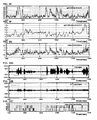
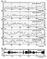
- FIG 9 consists of simulation results related to the overall operation of the hearing aid pertaining to this embodiment.
- FIG 9A shows the input signal for the main signal inputted to the hearing aid pertaining to this embodiment.
- FIG 9B is the output signal (only NS) in a conventional hearing aid.
- FIG. 9B shows a case in which only noise suppression processing (NS) is performed for suppressing the noise component included in the main signal, and the amplitude of the speech signal is reduced by noise suppression processing.
- NS noise suppression processing
- FIG 9C is the output signal (NS + NLC) of the hearing aid pertaining to this embodiment.
- FIG. 9C shows a case in which nonlinear compression processing (NLC), in which the main signal is amplified with a different gain (amplification ratio) for each frequency band, is performed after the performance of noise suppression processing (NS).
- NLC nonlinear compression processing
- NS noise suppression processing
- FIG. 9C the input/output amplitudes are compared, speech is kept at substantially the same signal strength, and noise is suppressed. This expresses the effect of the present invention.
- FIG 9D shows a speech detection flag (voice activity detection flag), which is intermediate data.
- FIGS. 9E to 9G each show intermediate data.
- FIG 9E shows the noise suppression gain Gns (gain by NS) resulting from the noise suppressor 702.
- FIG 9F shows the gain Gnlc (gain by NLC) resulting from the nonlinear compressor 127.
- FIG. 9G shows the total gain G resulting from the total gain calculator 130.
- the noise suppression gain Gns, gain Gnlc, and total gain G with respect to the 1 kHz band are shown as an example.
- FIG 10 shows simulation results related to the noise suppressor 702.
- FIG 10A shows an input signal of the main signal of the hearing aid pertaining to this embodiment.
- FIG 10B shows CTC output, which is the output of the residual speech suppressor 701.
- FIG 10C shows a speech detection flag, which is the output of the speech signal detector 501.
- FIGS. 10D to 10H show the noise suppression gain Gns (gain by NS) resulting from the noise suppressor 702 for each frequency band (500, 1000, 2000, 4000, 6000 Hz).
- FIG 11 shows simulation results related to the nonlinear compressor 127.
- FIG 11A shows the input signal of the main signal of the hearing aid pertaining to this embodiment.
- FIG 11B shows a speech detection flag.
- FIGS. 11C to 11G show the gain Gnlc (gain NLC) of the nonlinear compressor 127 for each frequency band (500, 1000, 2000, 4000, 6000 Hz).
- a band in which a plurality of bands is combined is referred to herein as a channel.
- FIG 12 shows simulation results related to the total gain calculator 130.
- FIG 12A shows the input signal of the main signal of the hearing aid pertaining to this embodiment.
- FIG 12B shows the output signal of the hearing aid pertaining to this embodiment.
- FIG 12C shows a speech detection flag.
- FIGS. 12D to 12H shows the total gain G of the total gain calculator 130 for each frequency band (500, 1000, 2000, 4000, 6000 Hz).
- the hearing aid of this embodiment comprises a plurality of microphones
- the steady noise component and non-steady noise component included in the speech signals inputted from the plurality of microphones can be detected and suppressed. Accordingly, the precision at which just the speech signal is amplified can be increased. Therefore, the signal strength of the speech signal can be controlled more accurately. As a result, even with wearers whose hearing varies greatly with just a minor change in sound volume due to a phenomenon called recruitment, discomfort caused by changes in sound volume can be lessened.
- the present invention can be utilized as a hearing aid with which speech can be clearly heard, which is achieved by combining noise suppression processing and nonlinear compression processing, and controlling the output according to noise and the desired signal.
Landscapes
- Health & Medical Sciences (AREA)
- General Health & Medical Sciences (AREA)
- Neurosurgery (AREA)
- Otolaryngology (AREA)
- Physics & Mathematics (AREA)
- Engineering & Computer Science (AREA)
- Acoustics & Sound (AREA)
- Signal Processing (AREA)
- Circuit For Audible Band Transducer (AREA)
- Adornments (AREA)
- Finger-Pressure Massage (AREA)
- Tone Control, Compression And Expansion, Limiting Amplitude (AREA)
- Control Of Amplification And Gain Control (AREA)
Claims (20)
- Hörgerät, Folgendes umfassend:ein Mikrofon (101, 101 F, 101 R) zum Erzeugen eines Eingangssignals von einem Eingangsgeräusch;ein Rauschunterdrückungselement (126, 502, 702), das betriebsbereit ist, um eine Rauschkomponentenstärke abzuschätzen, die in dem Eingangssignal eingeschlossen ist, auf der Basis einer Signalstärke für jedes von einer Mehrzahl von Frequenzbändern in dem Eingangssignal, und das betriebsbereit ist, um für jedes von der Mehrzahl von Frequenzbändern eine Rauschunterdrückungsverstärkung zu berechnen, um die Rauschkomponente, die in dem Eingangssignal eingeschlossen ist, auf der Basis der Rauschkomponentenstärke zu unterdrücken;einen Ausgleichswert-Rechner (129), der betriebsbereit ist, um einen Ausgleichswert für jedes von einer Mehrzahl von Frequenzbändern auf der Basis der Signalsstärke und der Rauschkomponentenstärke zu berechnen;einen Referenzverstärkungs-Informationsspeicher (128) zum Speichern von spezifischer Referenzverstärkungsinformation;einen nicht linearen Kompressor (127), der betriebsbereit ist, um eine Referenzverstärkung auf der Basis der Signalstärke und der spezifischen Referenzverstärkung für jedes von einer Mehrzahl von Frequenzbändern zu berechnen und die Referenzverstärkung auf der Basis des Ausgleichswertes einzustellen, und auf diese Weise betriebsbereit ist, für jedes von der Mehrzahl von Frequenzbändern eine nicht lineare Kompressionsverstärkung für eine nicht lineare Kompression und Verstärkung des Eingangssignals zu berechnen;eine Steuerung (131), die betriebsbereit ist, um ein Ausgangssignal zu erzeugen durch die Steuerung des Eingangsignals auf der Basis der Rauschunterdrückungsverstärkung und der nicht linearen Kompressionsverstärkung; undeinen Empfänger (103) für die Wiedergabe eines Ausgangsgeräusches von dem Ausgangssignal.
- Hörgerät nach Anspruch 1, wobei der Ausgleichswert-Rechner (129) betriebsbereit ist, um den Ausgleichswert zu verringern, wenn ein Verhältnis zwischen der Signalstärke und der Rauschkomponentenstärke kleiner als ein erster spezifischer Schwellenwert ist.
- Hörgerät nach Anspruch 2, wobei der Ausgleichswert-Rechner (129) betriebsbereit ist, um den Ausgleichswert zu erhöhen, wenn das Verhältnis zwischen der Signalstärke und der Rauschkomponentenstärke einem zweiten spezifischen Schwellenwert entspricht oder größer als dieser ist und dieser dem ersten spezifischen Schwellenwert entspricht oder größer als dieser ist.
- Hörgerät nach Anspruch 3, wobei der Ausgleichswert-Rechner (129) betriebsbereit ist, um den Ausgleichswert nicht zu erhöhen oder zu verringern, wenn das Verhältnis zwischen der Signalstärke und der Rauschkomponentenstärke dem ersten spezifischen Schwellenwert entspricht oder größer als dieser ist, und dieser kleiner als der zweite spezifische Schwellenwert ist.
- Hörgerät nach Anspruch 1, ferner umfassend einen Sprachsignaldetektor (501), der betriebsbereit ist, um ein Sprachsegment des Eingangssignals zu erfassen, wobei der Ausgleichswert-Rechner (129) betriebsbereit ist, um den Ausgleichswert auf der Basis zu steuern, ob das Sprachsegment von dem Sprachsignal-Detektor (501) erfasst wird oder nicht.
- Hörgerät nach Anspruch 5, wobei der Ausgleichswert-Rechner (129) betriebsbereit ist, um den Ausgleichswert zu erhöhen, wenn das Sprachsegment von dem Sprachsignal-Detektor (501) erfasst wird.
- Hörgerät nach Anspruch 5, wobei der Ausgleichswert-Rechner (129) betriebsbereit ist, um den Ausgleichswert zu verringern, wenn ein Nicht-Sprachsegment von dem Sprachsignal-Detektor (501) erfasst wird.
- Hörgerät nach Anspruch 5, wobei der Ausgleichswert-Rechner (129) betriebsbereit ist, um den Ausgleichswert nicht zu erhöhen oder zu verringern, wenn ein unbestimmtes Segment von dem Sprachsignai-Detektor (501) erfasst wird, bei dem unklar ist, ob es das Sprachsegment ist oder nicht.
- Hörgerät nach Anspruch 1, wobei der Ausgleichswert-Rechner (129) betriebsbereit ist, um als einen Maximalwert des Ausgleichswertes eine Inverse der Rauschunterdrückungsverstärkung zu bestimmen, berechnet für jedes spezifische Zeitsegment durch das Rauschunterdrückungselement (126, 502, 702).
- Hörgerät nach Anspruch 1, wobei der Ausgleichswert-Rechner (129) betriebsbereit ist, um als einen Minimalwert des Ausgleichswertes einen Wert festzusetzen, der durch das Dividieren eines Minimalwertes der Rauschunterdrückungsverstärkung durch die Rauschunterdrückungsverstärkung erzielt wird.
- Hörgerät nach Anspruch 3 oder 6, wobei, wenn der Ausgleichswert-Rechner (129) den Ausgleichswert erhöht, der nicht lineare Kompressor (127) betriebsbereit ist, um eine Zeitkonstante zu verlängern, durch die Steuerung der nicht linearen Kompressionsverstärkung in einer Richtung der Abnahme, und eine Zeitkonstante zu verkürzen, durch die Steuerung der nicht linearen Kompressionsverstärkung in einer Richtung der Zunahme.
- Hörgerät nach Anspruch 2 oder 7, wobei, wenn der Ausgleichswert-Rechner (129) den Ausgleichswert verringert, der nicht lineare Kompressor (127) betriebsbereit ist, um eine Zeitkonstante zu verkürzen, durch die Steuerung der nicht linearen Kompressionsverstärkung in einer Richtung der Abnahme, und eine Zeitkonstante zu verlängern, durch die Steuerung der nicht linearen Kompressionsverstärkung in einer Richtung der Zunahme.
- Hörgerät nach Anspruch 3 oder 4, wobei der Ausgleichswert-Rechner (129) betriebsbereit ist, um den ersten spezifischen Schwellenwert und den zweiten spezifischen Schwellenwert so zu bestimmen, dass sich ein konstanter Lautstärkepegel für jedes der Mehrzahl von Frequenzbändern ergibt.
- Hörgerät nach Anspruch 1, wobei der Ausgleichswert-Rechner (129) betriebsbereit ist, um als den Ausgleichswert eine Mehrzahl von Ausgleichswerten in verschiedenen Segmenten von der Mehrzahl von Frequenzbändern zu berechnen, und der nicht lineare Kompressor (127) betriebsbereit ist, um die nicht lineare Kompressionsverstärkung auf der Basis des Mittelwertes von der Mehrzahl von Ausgleichswerten zu steuern.
- Hörgerät nach Anspruch 1, wobei das Mikrofon (101, 101 F, 101 R) aus einer Mehrzahl von Mikrofonen (101, 101 F, 101 R) zusammengesetzt ist, und das Rauschunterdrückungselement (126, 502, 702) betriebsbereit ist, um als die Rauschkomponentenstärke, eine Rauschkomponentenstärke in einem stationären Zustand und eine Rauschkomponentenstärke in einem nicht-stationären Zustand für jedes von der Mehrzahl von Frequenzbändern abzuschätzen, auf der Basis der Signalstärken von der Mehrzahl von Eingangssignalen, erzeugt von der Mehrzahl von Mikrofonen (101, 101 F, 101 R).
- Hörgerät nach Anspruch 3 oder 4, wobei der Ausgleichswert-Rechner (129) betriebsbereit ist, um den ersten spezifischen Schwellenwert und den zweiten spezifischen Schwellenwert auf einer Niedrig-Frequenzband-Seite höher festzulegen als auf einer Hoch-Frequenzband-Seite.
- Hörgerät nach Anspruch 3 oder 4, wobei der Ausgleichswert-Rechner (129) betriebsbereit ist, um den ersten spezifischen Schwellenwert und den zweiten spezifischen Schwellenwert auf der Basis des Verhältnisses zwischen der Signalstärke einer Niedrigfrequenzband-Seite und der Geräuschkomponentenstärke der Niedrigfrequenzband-Seite zu bestimmen.
- Hörgerät nach Anspruch 3 oder 4, wobei der Ausgleichswert-Rechner (129) betriebsbereit ist, um den ersten spezifischen Schwellenwert und den zweiten spezifischen Schwellenwert auf der Basis des Verhältnisses zwischen der Signalstärke einer Niedrigfrequenzband-Seite und der Geräuschkomponentenstärke der Niedrigfrequenzband-Seite zu bestimmen.
- Hörgerät nach Anspruch 1, wobei der Ausgleichswert-Rechner (129) betriebsbereit ist, um eine Mehrzahl von Ausgleichswerten für jedes von der Mehrzahl von Frequenzbändern als den Ausgleichswert zu berechnen, und die Mehrzahl von Ausgleichswerten einen ersten Ausgleichswert und einen zweiten Ausgleichswert umfasst, wobei der zweite Ausgleichswert größer ist als der erste Ausgleichswert.
- Hörgerät nach Anspruch 1, wobei der Ausgleichswert-Rechner (129) betriebsbereit ist, um eine Mehrzahl von Ausgleichswerten für jedes von der Mehrzahl von Frequenzbändern als den Ausgleichswert zu berechnen, und die Mehrzahl von Ausgleichswerten einen ersten Ausgleichswert umfasst, der einen ersten Minimalwert aufweist, und einen zweiten Ausgleichswert umfasst, der einen zweiten Minimalwert aufweist, wobei der zweite Minimalwert größer ist als der erste Minimalwert.
Applications Claiming Priority (2)
| Application Number | Priority Date | Filing Date | Title |
|---|---|---|---|
| JP2009027145 | 2009-02-09 | ||
| PCT/JP2010/000471 WO2010089976A1 (ja) | 2009-02-09 | 2010-01-27 | 補聴器 |
Publications (3)
| Publication Number | Publication Date |
|---|---|
| EP2265039A1 EP2265039A1 (de) | 2010-12-22 |
| EP2265039A4 EP2265039A4 (de) | 2011-04-06 |
| EP2265039B1 true EP2265039B1 (de) | 2012-05-09 |
Family
ID=42541887
Family Applications (1)
| Application Number | Title | Priority Date | Filing Date |
|---|---|---|---|
| EP10738319A Not-in-force EP2265039B1 (de) | 2009-02-09 | 2010-01-27 | Hörgerät |
Country Status (5)
| Country | Link |
|---|---|
| US (1) | US8126176B2 (de) |
| EP (1) | EP2265039B1 (de) |
| JP (1) | JP4649546B2 (de) |
| AT (1) | ATE557551T1 (de) |
| WO (1) | WO2010089976A1 (de) |
Families Citing this family (18)
| Publication number | Priority date | Publication date | Assignee | Title |
|---|---|---|---|---|
| US8571231B2 (en) | 2009-10-01 | 2013-10-29 | Qualcomm Incorporated | Suppressing noise in an audio signal |
| DK2649812T3 (da) * | 2010-12-08 | 2014-08-04 | Widex As | Høreapparat og en fremgangsmåde til at forbedre talegengivelse |
| WO2012160602A1 (ja) * | 2011-05-24 | 2012-11-29 | 三菱電機株式会社 | 目的音強調装置およびカーナビゲーションシステム |
| KR20120131778A (ko) * | 2011-05-26 | 2012-12-05 | 삼성전자주식회사 | 청력 검사를 수행하는 방법과 이것을 이용한 청력 보조 장치 |
| US9386370B2 (en) * | 2013-09-04 | 2016-07-05 | Knowles Electronics, Llc | Slew rate control apparatus for digital microphones |
| GB201401689D0 (en) * | 2014-01-31 | 2014-03-19 | Microsoft Corp | Audio signal processing |
| TR201815883T4 (tr) * | 2014-03-17 | 2018-11-21 | Anheuser Busch Inbev Sa | Gürültü bastırılması. |
| JP6547451B2 (ja) * | 2015-06-26 | 2019-07-24 | 富士通株式会社 | 雑音抑圧装置、雑音抑圧方法、及び雑音抑圧プログラム |
| JP6536320B2 (ja) * | 2015-09-28 | 2019-07-03 | 富士通株式会社 | 音声信号処理装置、音声信号処理方法及びプログラム |
| US10504501B2 (en) | 2016-02-02 | 2019-12-10 | Dolby Laboratories Licensing Corporation | Adaptive suppression for removing nuisance audio |
| US10362412B2 (en) * | 2016-12-22 | 2019-07-23 | Oticon A/S | Hearing device comprising a dynamic compressive amplification system and a method of operating a hearing device |
| EP3503574B1 (de) * | 2017-12-22 | 2021-10-27 | FalCom A/S | Gehörschutzvorrichtung mit multiband-begrenzer und zugehöriges verfahren |
| CN108806707B (zh) * | 2018-06-11 | 2020-05-12 | 百度在线网络技术(北京)有限公司 | 语音处理方法、装置、设备及存储介质 |
| CN112151053B (zh) * | 2019-06-11 | 2024-04-16 | 北京汇钧科技有限公司 | 语音增强方法、系统、电子设备和存储介质 |
| JP2021164151A (ja) * | 2020-03-30 | 2021-10-11 | プレシードジャパン株式会社 | 集音装置 |
| JP7686439B2 (ja) * | 2020-08-27 | 2025-06-02 | キヤノン株式会社 | 音声処理装置、制御方法、およびプログラム |
| CN113362839B (zh) * | 2021-06-01 | 2024-10-01 | 平安科技(深圳)有限公司 | 音频数据处理方法、装置、计算机设备及存储介质 |
| WO2023228615A1 (ja) * | 2022-05-25 | 2023-11-30 | パナソニックIpマネジメント株式会社 | 音声特徴量算出方法、音声特徴量算出装置、及び、口腔機能評価装置 |
Family Cites Families (15)
| Publication number | Priority date | Publication date | Assignee | Title |
|---|---|---|---|---|
| JPS6217800A (ja) | 1985-07-16 | 1987-01-26 | シャープ株式会社 | 音声区間判定方式 |
| US4887299A (en) | 1987-11-12 | 1989-12-12 | Nicolet Instrument Corporation | Adaptive, programmable signal processing hearing aid |
| JP2502151B2 (ja) | 1989-06-10 | 1996-05-29 | 株式会社日立製作所 | プ―リの加工方法及びプ―リ |
| JPH05173592A (ja) | 1991-12-25 | 1993-07-13 | Matsushita Electric Ind Co Ltd | 音声/非音声判別方法および判別装置 |
| JP3345534B2 (ja) | 1994-10-14 | 2002-11-18 | 松下電器産業株式会社 | 補聴器 |
| JP2953397B2 (ja) * | 1996-09-13 | 1999-09-27 | 日本電気株式会社 | ディジタル補聴器の聴覚補償処理方法及びディジタル補聴器 |
| WO2001001732A1 (en) | 1999-06-24 | 2001-01-04 | Tøpholm & Westermann APS | Hearing aid with controllable directional characteristics |
| JP3794881B2 (ja) * | 1999-10-25 | 2006-07-12 | リオン株式会社 | 補聴装置 |
| US6754355B2 (en) | 1999-12-21 | 2004-06-22 | Texas Instruments Incorporated | Digital hearing device, method and system |
| US7333623B2 (en) | 2002-03-26 | 2008-02-19 | Oticon A/S | Method for dynamic determination of time constants, method for level detection, method for compressing an electric audio signal and hearing aid, wherein the method for compression is used |
| CN1640191B (zh) | 2002-07-12 | 2011-07-20 | 唯听助听器公司 | 助听器和提高语言清晰度的方法 |
| JP3894875B2 (ja) * | 2002-11-05 | 2007-03-22 | リオン株式会社 | 補聴装置 |
| JP4286637B2 (ja) | 2002-11-18 | 2009-07-01 | パナソニック株式会社 | マイクロホン装置および再生装置 |
| DE102006051071B4 (de) * | 2006-10-30 | 2010-12-16 | Siemens Audiologische Technik Gmbh | Pegelabhängige Geräuschreduktion |
| WO2008116264A1 (en) | 2007-03-26 | 2008-10-02 | Cochlear Limited | Noise reduction in auditory prostheses |
-
2010
- 2010-01-27 EP EP10738319A patent/EP2265039B1/de not_active Not-in-force
- 2010-01-27 JP JP2010539077A patent/JP4649546B2/ja active Active
- 2010-01-27 WO PCT/JP2010/000471 patent/WO2010089976A1/ja not_active Ceased
- 2010-01-27 US US12/935,687 patent/US8126176B2/en active Active
- 2010-01-27 AT AT10738319T patent/ATE557551T1/de active
Also Published As
| Publication number | Publication date |
|---|---|
| JPWO2010089976A1 (ja) | 2012-08-09 |
| EP2265039A4 (de) | 2011-04-06 |
| US20110013792A1 (en) | 2011-01-20 |
| JP4649546B2 (ja) | 2011-03-09 |
| US8126176B2 (en) | 2012-02-28 |
| ATE557551T1 (de) | 2012-05-15 |
| EP2265039A1 (de) | 2010-12-22 |
| WO2010089976A1 (ja) | 2010-08-12 |
Similar Documents
| Publication | Publication Date | Title |
|---|---|---|
| EP2265039B1 (de) | Hörgerät | |
| KR100860805B1 (ko) | 음성 강화 시스템 | |
| EP2283484B1 (de) | System und verfahren für dynamische klangwiedergabe | |
| TWI463817B (zh) | 可適性智慧雜訊抑制系統及方法 | |
| KR101837331B1 (ko) | 보청기 시스템을 동작시키는 방법 및 보청기 시스템 | |
| CN117321681A (zh) | 嘈杂环境中的语音优化 | |
| CN103874002A (zh) | 包括非自然信号减少的音频处理装置 | |
| JPWO2010131470A1 (ja) | ゲイン制御装置及びゲイン制御方法、音声出力装置 | |
| WO2010146711A1 (ja) | 音声信号処理装置及び音声信号処理方法 | |
| JP5903921B2 (ja) | ノイズ低減装置、音声入力装置、無線通信装置、ノイズ低減方法、およびノイズ低減プログラム | |
| US9640168B2 (en) | Noise cancellation with dynamic range compression | |
| US20080082327A1 (en) | Sound Processing Apparatus | |
| JPWO2011055489A1 (ja) | 補聴器 | |
| CN114257917A (zh) | 用于耳机的噪声处理方法、系统及耳机 | |
| CN112437957A (zh) | 用于全面收听的强加间隙插入 | |
| JP2009296298A (ja) | 音声信号処理装置および方法 | |
| WO2012098856A1 (ja) | 補聴器、及び、補聴器の制御方法 | |
| JPH09311696A (ja) | 自動利得調整装置 | |
| JP5149872B2 (ja) | 音響信号送信装置、音響信号受信装置、音響信号送信方法、音響信号受信方法及びそのプログラム | |
| RU2589298C1 (ru) | Способ повышения разборчивости и информативности звуковых сигналов в шумовой обстановке | |
| JP5277355B1 (ja) | 信号処理装置及び補聴器並びに信号処理方法 | |
| JP4437112B2 (ja) | 音声信号処理装置 | |
| JP2023130254A (ja) | 音声処理装置および音声処理方法 | |
| WO2024202349A1 (ja) | 自動利得制御装置、エコー除去装置、自動利得制御方法及び自動利得制御プログラム | |
| JP4479625B2 (ja) | 騒音抑圧装置 |
Legal Events
| Date | Code | Title | Description |
|---|---|---|---|
| PUAI | Public reference made under article 153(3) epc to a published international application that has entered the european phase |
Free format text: ORIGINAL CODE: 0009012 |
|
| 17P | Request for examination filed |
Effective date: 20100930 |
|
| AK | Designated contracting states |
Kind code of ref document: A1 Designated state(s): AT BE BG CH CY CZ DE DK EE ES FI FR GB GR HR HU IE IS IT LI LT LU LV MC MK MT NL NO PL PT RO SE SI SK SM TR |
|
| AX | Request for extension of the european patent |
Extension state: AL BA RS |
|
| A4 | Supplementary search report drawn up and despatched |
Effective date: 20110307 |
|
| GRAP | Despatch of communication of intention to grant a patent |
Free format text: ORIGINAL CODE: EPIDOSNIGR1 |
|
| GRAS | Grant fee paid |
Free format text: ORIGINAL CODE: EPIDOSNIGR3 |
|
| GRAA | (expected) grant |
Free format text: ORIGINAL CODE: 0009210 |
|
| DAX | Request for extension of the european patent (deleted) | ||
| AK | Designated contracting states |
Kind code of ref document: B1 Designated state(s): AT BE BG CH CY CZ DE DK EE ES FI FR GB GR HR HU IE IS IT LI LT LU LV MC MK MT NL NO PL PT RO SE SI SK SM TR |
|
| REG | Reference to a national code |
Ref country code: GB Ref legal event code: FG4D |
|
| REG | Reference to a national code |
Ref country code: CH Ref legal event code: EP Ref country code: AT Ref legal event code: REF Ref document number: 557551 Country of ref document: AT Kind code of ref document: T Effective date: 20120515 |
|
| REG | Reference to a national code |
Ref country code: IE Ref legal event code: FG4D |
|
| REG | Reference to a national code |
Ref country code: DE Ref legal event code: R096 Ref document number: 602010001520 Country of ref document: DE Effective date: 20120712 |
|
| REG | Reference to a national code |
Ref country code: NL Ref legal event code: VDEP Effective date: 20120509 |
|
| REG | Reference to a national code |
Ref country code: LT Ref legal event code: MG4D Effective date: 20120509 |
|
| PG25 | Lapsed in a contracting state [announced via postgrant information from national office to epo] |
Ref country code: NO Free format text: LAPSE BECAUSE OF FAILURE TO SUBMIT A TRANSLATION OF THE DESCRIPTION OR TO PAY THE FEE WITHIN THE PRESCRIBED TIME-LIMIT Effective date: 20120809 Ref country code: SE Free format text: LAPSE BECAUSE OF FAILURE TO SUBMIT A TRANSLATION OF THE DESCRIPTION OR TO PAY THE FEE WITHIN THE PRESCRIBED TIME-LIMIT Effective date: 20120509 Ref country code: PL Free format text: LAPSE BECAUSE OF FAILURE TO SUBMIT A TRANSLATION OF THE DESCRIPTION OR TO PAY THE FEE WITHIN THE PRESCRIBED TIME-LIMIT Effective date: 20120509 Ref country code: CY Free format text: LAPSE BECAUSE OF FAILURE TO SUBMIT A TRANSLATION OF THE DESCRIPTION OR TO PAY THE FEE WITHIN THE PRESCRIBED TIME-LIMIT Effective date: 20120509 Ref country code: IS Free format text: LAPSE BECAUSE OF FAILURE TO SUBMIT A TRANSLATION OF THE DESCRIPTION OR TO PAY THE FEE WITHIN THE PRESCRIBED TIME-LIMIT Effective date: 20120909 Ref country code: FI Free format text: LAPSE BECAUSE OF FAILURE TO SUBMIT A TRANSLATION OF THE DESCRIPTION OR TO PAY THE FEE WITHIN THE PRESCRIBED TIME-LIMIT Effective date: 20120509 Ref country code: LT Free format text: LAPSE BECAUSE OF FAILURE TO SUBMIT A TRANSLATION OF THE DESCRIPTION OR TO PAY THE FEE WITHIN THE PRESCRIBED TIME-LIMIT Effective date: 20120509 |
|
| REG | Reference to a national code |
Ref country code: AT Ref legal event code: MK05 Ref document number: 557551 Country of ref document: AT Kind code of ref document: T Effective date: 20120509 |
|
| PG25 | Lapsed in a contracting state [announced via postgrant information from national office to epo] |
Ref country code: SI Free format text: LAPSE BECAUSE OF FAILURE TO SUBMIT A TRANSLATION OF THE DESCRIPTION OR TO PAY THE FEE WITHIN THE PRESCRIBED TIME-LIMIT Effective date: 20120509 Ref country code: GR Free format text: LAPSE BECAUSE OF FAILURE TO SUBMIT A TRANSLATION OF THE DESCRIPTION OR TO PAY THE FEE WITHIN THE PRESCRIBED TIME-LIMIT Effective date: 20120810 Ref country code: HR Free format text: LAPSE BECAUSE OF FAILURE TO SUBMIT A TRANSLATION OF THE DESCRIPTION OR TO PAY THE FEE WITHIN THE PRESCRIBED TIME-LIMIT Effective date: 20120509 Ref country code: LV Free format text: LAPSE BECAUSE OF FAILURE TO SUBMIT A TRANSLATION OF THE DESCRIPTION OR TO PAY THE FEE WITHIN THE PRESCRIBED TIME-LIMIT Effective date: 20120509 Ref country code: PT Free format text: LAPSE BECAUSE OF FAILURE TO SUBMIT A TRANSLATION OF THE DESCRIPTION OR TO PAY THE FEE WITHIN THE PRESCRIBED TIME-LIMIT Effective date: 20120910 |
|
| PG25 | Lapsed in a contracting state [announced via postgrant information from national office to epo] |
Ref country code: BE Free format text: LAPSE BECAUSE OF FAILURE TO SUBMIT A TRANSLATION OF THE DESCRIPTION OR TO PAY THE FEE WITHIN THE PRESCRIBED TIME-LIMIT Effective date: 20120509 |
|
| PG25 | Lapsed in a contracting state [announced via postgrant information from national office to epo] |
Ref country code: CZ Free format text: LAPSE BECAUSE OF FAILURE TO SUBMIT A TRANSLATION OF THE DESCRIPTION OR TO PAY THE FEE WITHIN THE PRESCRIBED TIME-LIMIT Effective date: 20120509 Ref country code: NL Free format text: LAPSE BECAUSE OF FAILURE TO SUBMIT A TRANSLATION OF THE DESCRIPTION OR TO PAY THE FEE WITHIN THE PRESCRIBED TIME-LIMIT Effective date: 20120509 Ref country code: EE Free format text: LAPSE BECAUSE OF FAILURE TO SUBMIT A TRANSLATION OF THE DESCRIPTION OR TO PAY THE FEE WITHIN THE PRESCRIBED TIME-LIMIT Effective date: 20120509 Ref country code: AT Free format text: LAPSE BECAUSE OF FAILURE TO SUBMIT A TRANSLATION OF THE DESCRIPTION OR TO PAY THE FEE WITHIN THE PRESCRIBED TIME-LIMIT Effective date: 20120509 Ref country code: DK Free format text: LAPSE BECAUSE OF FAILURE TO SUBMIT A TRANSLATION OF THE DESCRIPTION OR TO PAY THE FEE WITHIN THE PRESCRIBED TIME-LIMIT Effective date: 20120509 Ref country code: SK Free format text: LAPSE BECAUSE OF FAILURE TO SUBMIT A TRANSLATION OF THE DESCRIPTION OR TO PAY THE FEE WITHIN THE PRESCRIBED TIME-LIMIT Effective date: 20120509 Ref country code: RO Free format text: LAPSE BECAUSE OF FAILURE TO SUBMIT A TRANSLATION OF THE DESCRIPTION OR TO PAY THE FEE WITHIN THE PRESCRIBED TIME-LIMIT Effective date: 20120509 |
|
| PG25 | Lapsed in a contracting state [announced via postgrant information from national office to epo] |
Ref country code: IT Free format text: LAPSE BECAUSE OF FAILURE TO SUBMIT A TRANSLATION OF THE DESCRIPTION OR TO PAY THE FEE WITHIN THE PRESCRIBED TIME-LIMIT Effective date: 20120509 |
|
| PLBE | No opposition filed within time limit |
Free format text: ORIGINAL CODE: 0009261 |
|
| STAA | Information on the status of an ep patent application or granted ep patent |
Free format text: STATUS: NO OPPOSITION FILED WITHIN TIME LIMIT |
|
| 26N | No opposition filed |
Effective date: 20130212 |
|
| PG25 | Lapsed in a contracting state [announced via postgrant information from national office to epo] |
Ref country code: ES Free format text: LAPSE BECAUSE OF FAILURE TO SUBMIT A TRANSLATION OF THE DESCRIPTION OR TO PAY THE FEE WITHIN THE PRESCRIBED TIME-LIMIT Effective date: 20120820 |
|
| REG | Reference to a national code |
Ref country code: DE Ref legal event code: R097 Ref document number: 602010001520 Country of ref document: DE Effective date: 20130212 |
|
| PG25 | Lapsed in a contracting state [announced via postgrant information from national office to epo] |
Ref country code: BG Free format text: LAPSE BECAUSE OF FAILURE TO SUBMIT A TRANSLATION OF THE DESCRIPTION OR TO PAY THE FEE WITHIN THE PRESCRIBED TIME-LIMIT Effective date: 20120809 |
|
| PG25 | Lapsed in a contracting state [announced via postgrant information from national office to epo] |
Ref country code: MC Free format text: LAPSE BECAUSE OF NON-PAYMENT OF DUE FEES Effective date: 20130131 |
|
| REG | Reference to a national code |
Ref country code: IE Ref legal event code: MM4A |
|
| REG | Reference to a national code |
Ref country code: FR Ref legal event code: ST Effective date: 20130930 |
|
| PG25 | Lapsed in a contracting state [announced via postgrant information from national office to epo] |
Ref country code: FR Free format text: LAPSE BECAUSE OF NON-PAYMENT OF DUE FEES Effective date: 20130131 |
|
| PG25 | Lapsed in a contracting state [announced via postgrant information from national office to epo] |
Ref country code: IE Free format text: LAPSE BECAUSE OF NON-PAYMENT OF DUE FEES Effective date: 20130127 |
|
| PGFP | Annual fee paid to national office [announced via postgrant information from national office to epo] |
Ref country code: DE Payment date: 20140122 Year of fee payment: 5 |
|
| PG25 | Lapsed in a contracting state [announced via postgrant information from national office to epo] |
Ref country code: MT Free format text: LAPSE BECAUSE OF FAILURE TO SUBMIT A TRANSLATION OF THE DESCRIPTION OR TO PAY THE FEE WITHIN THE PRESCRIBED TIME-LIMIT Effective date: 20120509 |
|
| PGFP | Annual fee paid to national office [announced via postgrant information from national office to epo] |
Ref country code: GB Payment date: 20140121 Year of fee payment: 5 |
|
| REG | Reference to a national code |
Ref country code: CH Ref legal event code: PL |
|
| PG25 | Lapsed in a contracting state [announced via postgrant information from national office to epo] |
Ref country code: LI Free format text: LAPSE BECAUSE OF NON-PAYMENT OF DUE FEES Effective date: 20140131 Ref country code: CH Free format text: LAPSE BECAUSE OF NON-PAYMENT OF DUE FEES Effective date: 20140131 |
|
| PG25 | Lapsed in a contracting state [announced via postgrant information from national office to epo] |
Ref country code: SM Free format text: LAPSE BECAUSE OF FAILURE TO SUBMIT A TRANSLATION OF THE DESCRIPTION OR TO PAY THE FEE WITHIN THE PRESCRIBED TIME-LIMIT Effective date: 20120509 |
|
| PG25 | Lapsed in a contracting state [announced via postgrant information from national office to epo] |
Ref country code: TR Free format text: LAPSE BECAUSE OF FAILURE TO SUBMIT A TRANSLATION OF THE DESCRIPTION OR TO PAY THE FEE WITHIN THE PRESCRIBED TIME-LIMIT Effective date: 20120509 |
|
| PG25 | Lapsed in a contracting state [announced via postgrant information from national office to epo] |
Ref country code: LU Free format text: LAPSE BECAUSE OF NON-PAYMENT OF DUE FEES Effective date: 20130127 Ref country code: HU Free format text: LAPSE BECAUSE OF FAILURE TO SUBMIT A TRANSLATION OF THE DESCRIPTION OR TO PAY THE FEE WITHIN THE PRESCRIBED TIME-LIMIT; INVALID AB INITIO Effective date: 20100127 Ref country code: MK Free format text: LAPSE BECAUSE OF FAILURE TO SUBMIT A TRANSLATION OF THE DESCRIPTION OR TO PAY THE FEE WITHIN THE PRESCRIBED TIME-LIMIT Effective date: 20120509 |
|
| REG | Reference to a national code |
Ref country code: DE Ref legal event code: R119 Ref document number: 602010001520 Country of ref document: DE |
|
| GBPC | Gb: european patent ceased through non-payment of renewal fee |
Effective date: 20150127 |
|
| PG25 | Lapsed in a contracting state [announced via postgrant information from national office to epo] |
Ref country code: GB Free format text: LAPSE BECAUSE OF NON-PAYMENT OF DUE FEES Effective date: 20150127 Ref country code: DE Free format text: LAPSE BECAUSE OF NON-PAYMENT OF DUE FEES Effective date: 20150801 |