EP2263632A1 - Assembly forming the side, head and foot parts of a bed with a movement transfer means and bed with such an assembly - Google Patents
Assembly forming the side, head and foot parts of a bed with a movement transfer means and bed with such an assembly Download PDFInfo
- Publication number
- EP2263632A1 EP2263632A1 EP09163140A EP09163140A EP2263632A1 EP 2263632 A1 EP2263632 A1 EP 2263632A1 EP 09163140 A EP09163140 A EP 09163140A EP 09163140 A EP09163140 A EP 09163140A EP 2263632 A1 EP2263632 A1 EP 2263632A1
- Authority
- EP
- European Patent Office
- Prior art keywords
- post
- parts
- arrangement according
- arrangement
- post part
- Prior art date
- Legal status (The legal status is an assumption and is not a legal conclusion. Google has not performed a legal analysis and makes no representation as to the accuracy of the status listed.)
- Granted
Links
Images


Classifications
-
- A—HUMAN NECESSITIES
- A61—MEDICAL OR VETERINARY SCIENCE; HYGIENE
- A61G—TRANSPORT, PERSONAL CONVEYANCES, OR ACCOMMODATION SPECIALLY ADAPTED FOR PATIENTS OR DISABLED PERSONS; OPERATING TABLES OR CHAIRS; CHAIRS FOR DENTISTRY; FUNERAL DEVICES
- A61G7/00—Beds specially adapted for nursing; Devices for lifting patients or disabled persons
- A61G7/05—Parts, details or accessories of beds
- A61G7/0507—Side-rails
- A61G7/0508—Side-rails characterised by a particular connection mechanism
- A61G7/0509—Side-rails characterised by a particular connection mechanism sliding or pivoting downwards
-
- A—HUMAN NECESSITIES
- A61—MEDICAL OR VETERINARY SCIENCE; HYGIENE
- A61G—TRANSPORT, PERSONAL CONVEYANCES, OR ACCOMMODATION SPECIALLY ADAPTED FOR PATIENTS OR DISABLED PERSONS; OPERATING TABLES OR CHAIRS; CHAIRS FOR DENTISTRY; FUNERAL DEVICES
- A61G7/00—Beds specially adapted for nursing; Devices for lifting patients or disabled persons
- A61G7/05—Parts, details or accessories of beds
- A61G7/0507—Side-rails
- A61G7/0512—Side-rails characterised by customised length
- A61G7/0513—Side-rails characterised by customised length covering particular sections of the bed, e.g. one or more partial side-rail sections along the bed
-
- A—HUMAN NECESSITIES
- A61—MEDICAL OR VETERINARY SCIENCE; HYGIENE
- A61G—TRANSPORT, PERSONAL CONVEYANCES, OR ACCOMMODATION SPECIALLY ADAPTED FOR PATIENTS OR DISABLED PERSONS; OPERATING TABLES OR CHAIRS; CHAIRS FOR DENTISTRY; FUNERAL DEVICES
- A61G7/00—Beds specially adapted for nursing; Devices for lifting patients or disabled persons
- A61G7/05—Parts, details or accessories of beds
- A61G7/0507—Side-rails
- A61G7/0516—Side-rails with height adjustability
Definitions
- the present invention relates to an arrangement forming a side, head or foot section for a bed, in particular for a hospital or nursing bed, with partially lowerable side and / or head or foot parts.
- the assembly includes a first telescoping post and a second telescoping post, each having a first post part and a second post part.
- the first post parts and the second post parts are displaceable between one another in a pushed position and an extended position.
- the first post part of the first post and the first post part of the second post are rigidly connected to each other via a first spar and form a first part with the first spar.
- the second post part of the first post and the second post part of the second post are rigidly connected to each other via a second spar and form a second part with the second spar.
- the first part is referred to as the lower part and the second part as the middle part of the arrangement.
- the side parts as disclosed in the cited document, have a width which corresponds to approximately half the length of the bed. On each side of the bed two side parts are provided. Each of the two side panels makes it possible to secure the lying surface over approximately half the length of the bed. A reliable backup is given according to the regulations only if both sides are pulled out.
- the arrangement has at least one first motion transmission means.
- the movement transmitting means transmits a movement between the first post part and the second post part of the first post on at least one of the two post parts of the second post.
- the first Motion transfer means transmit a movement between the first post part and the second post part of the second post on at least one of the two post parts of the first post.
- first movement transmission means thus takes place a kinematic coupling between the post parts of the first post and the second post and vice versa.
- a first advantageous variant for a first motion transmission means may comprise a shaft. This shaft then extends between the first post and the second post. When moving between the first post part and the second post part of one of the two posts, the shaft rotates to transmit the movement to the post parts of the other of the two posts.
- the shaft of the first motion transmission gear wheels can be rotatably mounted.
- the shaft is rotatably supported either on the first post parts of the first post and the second post, while on the second post parts of the first post and the second post racks are mounted, in which engage the gears.
- the shaft is rotatably mounted on the second post parts of the first post and the second post. Then at the first post parts of the first Pole and the second post racks attached, in which the gears then intervene.
- the arrangement in a second variant it is possible for the arrangement to comprise a first flexible tension member, e.g. a rope, a chain, a band or the like.
- This first flexible tension member is then connected to the first post part facing away from the end of the second post part of the first post and the first post part facing the end of the second post part of the second post. A movement of the second post part of the first post can thereby be transferred to the second post part of the second post.
- the first motion transmission means may comprise a second flexible tension member, e.g. a rope, a chain or a band or the like. This second pulling member is then connected to the end facing away from the first post part of the second post part of the second post and to the first post part facing the end of the second post part of the first post.
- a second flexible tension member e.g. a rope, a chain or a band or the like. This second pulling member is then connected to the end facing away from the first post part of the second post part of the second post and to the first post part facing the end of the second post part of the first post.
- each tension member under the deflection roller is in the region of the end facing the first post part, about the deflection roller in the region of the end of the other second post part facing the first post part Guide roller around to the first post part facing the end of the other second post part.
- the first post and the second post of an arrangement according to the invention may each have a third post part.
- the second post part and the third post part may be suitable and arranged to be displaced between one another in a pushed position and an extended position to each other.
- the third post part of the first post and the third post part of the second post may be rigidly connected to each other via a third spar. Together with the third spar, the third post parts may form a third part of the assembly.
- An arrangement according to the invention with such a third part can have a second motion transmission means.
- This second movement transmission means can transmit a movement between the second post part and the third post part of the first post to the second post part and / or third post part of the second post.
- the second movement transmission means can transmit a movement between the second post part and the third post part of the second post to the second post part and / or the third post part of the first post.
- This also a smooth sliding of the second part and the third part or the second post parts and the third post parts to each other is possible.
- the second motion transmission means may be formed according to one of the above-described first motion transmission means. So it may either have a shaft or comprise one or two tension members.
- An inventive bed with partially lowerable side and / or head or foot parts can be designed so that the
- the side parts according to the invention shown in the figures comprise a lower part U as a first part, a middle part M as a second part and an upper part O as a third part.
- the lower part U, the middle part M and the upper part O are extendable and insertable connected to each other.
- the lower part U comprises a first post part 11 of a first post 10 and a first post part 21 of a second post 20.
- the middle part M comprises a second post part 12 of the first post 10, a first spar 31, a second spar 32 and a second post part 22 of the second post 20.
- the two second post parts 12, 22 are fixedly connected to each other, via the first Spar 3 and the second spar 32.
- the upper part O is formed. It comprises a third post part 13 of the first post 10, a third post 33 and a third post part 23 of the second post 2.
- the spar 33 connects the third post part 13 of the first post 10 and the third post part 23 of the second post 20 rigidly together.
- the first post part 11, the second post part 12 and the third post part 13 of the first post 10 are telescopically extendable as well as the first post part 21, the second post part 22 and the third post part 23 of the second post 20.
- the first post part 11, 21, the second post part 12, 22 and the third Post part 13, 23 of the first and the second post 10, 20 are formed by hollow profile, of which the first post part has the largest cross section and the third post part has the smallest cross section ( FIG. 1a, 1b ).
- the design of the post parts of the first post 10 and the second post 20 substantially corresponds to that in the document EP 2 052 707 A1 disclosed.
- the first part U, the second part M and the third part O can be fixed to each other in different positions.
- the parts U, M, O can be completely pushed into each other or completely pulled out. It can also be taken intermediate positions.
- There are holding means 61, 62 are provided, with which the post parts 11, 12, 13, 21, 22, 23 can be locked in the different positions against each other.
- About solvents 63, 64, these holding means 61, 62 can be solved if the side part is to be further extended or pushed further into each other.
- the page corresponds to the part in the publication EP 2 052 707 A1 revealed side part.
- release mechanism for releasing the retaining means 61, 62 there is a difference between the known side part and the side parts according to the invention, which is due to the fact that the side part according to the invention is longer than the previously known.
- release buttons 65 are provided, not on the post 10, 20 but of the posts 10, 20 offset inwardly on the third rail 33 are attached.
- the trigger buttons 65 cooperate with a respective pivotable lever 66 which is pivotally mounted on the third spar 33.
- the pivotable levers 66 have a pivoting section 661, on the one hand a section of which extends to the trigger button 65 and, on the other hand, a section of a trigger rod 63.
- the pivotable levers 66 are shaped so that when pressed on the trigger buttons 65, the trigger rods 63 are raised to release in particular the holding means 61.
- the essential new of the side part according to the invention is a movement coupling between the first and the second post part 11, 12 of the first post 10 on the one hand and the first and the second post part 21, 22 of the second post 20 on the other hand and also between the second and the third Post part 12, 13 of the first post 10 on the one hand and the second and the third post part 22, 23 of the second post 20 on the other hand is provided.
- These couplings allow smooth movement of the second part M to the first part U and the third part O to the second part M.
- the motion coupling is achieved by a first motion transmission means 40 and a second motion transmission means 50.
- the first movement transmission means 40 comprises a shaft 41. More specifically, the shaft is mounted between the first post 10 and the second post 20 between the second post parts 12, 22 of the first post 10 and the second post 20 in the first post 31. At the ends of the shaft 41 gears 42 are mounted. The gears 42 engage in racks 43, which are attached to the first post parts 11, 21. Will now the second post part 12, 22 of the two posts 10, 20 with respect to the first post part 11, 21 of the same post 10, 20, this displacement causes a rotation of the shaft 41. The movement is then transmitted to the other post 20, 10 via the shaft 41. The gear 42 on the other post 20, 10 rolls in the rack on the first post part 21, 11 of the other post 20, 10 and thus transmits the movement of the one on the other post. For a smooth movement of the second part M relative to the first part U is possible.
- the second motion transmission means 50 which couples the movement between the second part M and the third part O, has two tension members 51, 52.
- the first tension member 51 and the second tension member 52 (see FIG. 3a ) are attached to the third spar 33 at a first end.
- the ends of the tension members 51, 52 are each provided with a nipple, which are held clamped in a respective recess 331 in the third spar 33.
- the tension members 51, 52 are guided from the recesses 331 to the third post parts 13, 23 of the first post 10 and the second post 20, respectively. From the upper ends of the third post parts 13, 23, the tension members 51, 52 are then guided down to the lower ends thereof.
- each guide rollers 53 are attached.
- the tension members 51, 52 are deflected.
- the tension members 51, 52 are then guided by the second spar 32 to the respective other guide rollers 53.
- the tension members 51, 52 are deflected again to be subsequently attached to the lower ends of the third post parts 23, 13 of the second post 20 and the first post 10.
- the second ends of the tension members 51, 52 also have for this purpose a nipple 512 which is fixed in a bore of the third post part 13, 23 by means of a screw.
- the upper end of the third post part 13 of the first post 10 is kinematically coupled to the lower end of the third post part 23 of the second post 20 via the first tension member 51.
- a movement of a post part is thus transferred to the other post part.
- the upper end of the third post part 23 of the second post 20 is kinematically coupled to the lower end of the third post part 13 of the first post 10. Again, the movement of the one post part is transferred to the other post part by the tension member 52.
Abstract
Description
Die vorliegende Erfindung betrifft eine Anordnung bildend ein Seiten-, Kopf- oder Fußteil für ein Bett, insbesondere für ein Kranken- oder Pflegebett, mit teilweise absenkbaren Seiten- und/oder Kopf- bzw. Fußteilen.The present invention relates to an arrangement forming a side, head or foot section for a bed, in particular for a hospital or nursing bed, with partially lowerable side and / or head or foot parts.
Aus der Druckschrift mit der Veröffentlichungsnummer
Die Seitenteile, wie sie in der genannten Druckschrift offenbart sind, haben eine Breite, die ungefähr der Hälfte der Länge des Bettes entspricht. An jeder Bettseite sind zwei Seitenteile vorgesehen. Jedes der beiden Seitenteile ermöglicht ein Sichern der Liegefläche über etwa die Hälfte der Länge des Bettes. Eine zuverlässige Sicherung ist nach den Vorschriften nur dann gegeben, wenn beide Seitenteile ausgezogen sind.The side parts, as disclosed in the cited document, have a width which corresponds to approximately half the length of the bed. On each side of the bed two side parts are provided. Each of the two side panels makes it possible to secure the lying surface over approximately half the length of the bed. A reliable backup is given according to the regulations only if both sides are pulled out.
Aus psychologischer Sicht des Bewohners eines Pflegebettes kann es gewünscht sein, dass nicht die gesamte Länge des Bettes durch ein Seitenteil gesichert wird. Vielmehr ist es oft gewünscht, dass nur Abschnitte der Länge der Bettseite durch ein Seitenteil gesichert sind. Gleichzeitig soll allerdings eine Sicherung der Art erfolgen, dass ein Herausfallen des Bewohners aus dem Bett bei bestimmungsgemäßen Gebrauch des Bettes ausgeschlossen ist.From a psychological point of view of the resident of a care bed, it may be desired that not the entire length of the bed is secured by a side panel. Rather, it is often desired that only Sections of the length of the bed side are secured by a side panel. At the same time, however, a safeguard of the type is to be made that falling out of the resident is excluded from the bed in accordance with the intended use of the bed.
Um den Bedürfnissen des Bewohners entgegenzukommen, wurden verschiedentlich Seitenteile vorgeschlagen, die sich über mehr als die Hälfte der Länge des Bettes, zum Beispiel über dreiviertel der Bettseite erstrecken.To accommodate the needs of the resident, various side panels have been proposed that extend over more than half the length of the bed, for example, over three quarters of the bed side.
Überträgt man nun die Idee der verlängerten Seitenteile auf die Seitenteile, wie sie durch eine Anordnung gemäß der Druckschrift
Es stellt sich somit das Problem, eine Anordnung, wie sie z.B. aus der Druckschrift
Dieses Problem wird erfindungsgemäß dadurch gelöst, dass die Anordnung wenigstens ein erstes Bewegungsübertragungsmittel aufweist. Das Bewegungsübertragungsmittel überträgt eine Bewegung zwischen dem ersten Pfostenteil und dem zweiten Pfostenteil des ersten Pfostens auf zumindest eines der beiden Pfostenteile des zweiten Pfostens. Alternativ oder zusätzlich kann das erste Bewegungsübertragungsmittel eine Bewegung zwischen dem ersten Pfostenteil und dem zweiten Pfostenteil des zweiten Pfostens auf zumindest eines der beiden Pfostenteile des ersten Pfostens übertragen.This problem is solved according to the invention in that the arrangement has at least one first motion transmission means. The movement transmitting means transmits a movement between the first post part and the second post part of the first post on at least one of the two post parts of the second post. Alternatively or additionally, the first Motion transfer means transmit a movement between the first post part and the second post part of the second post on at least one of the two post parts of the first post.
Durch das erste Bewegungsübertragungsmittel erfolgt somit eine kinematische Kopplung zwischen den Pfostenteilen des ersten Pfostens und des zweiten Pfostens und umgekehrt. Durch diese kinematische Kopplung mittels des ersten Bewegungsübertragungsmittel kann ein Verkanten der Pfostenteile des ersten Pfostens und der Pfostenteile des zweiten Pfostens vermieden werden, selbst wenn die Kraft zum Einfahren und Ausziehen der Pfosten nur an einem der Pfosten bzw. an einer Seite der Anordnung aufgebracht wird.By the first movement transmission means thus takes place a kinematic coupling between the post parts of the first post and the second post and vice versa. By this kinematic coupling by means of the first movement transmission means, tilting of the post parts of the first post and the post parts of the second post can be avoided, even if the force for retracting and extending the posts is applied only to one of the posts or to one side of the assembly.
Eine erste vorteilhafte Variante für ein erstes Bewegungsübertragungsmittel kann eine Welle umfassen. Diese Welle erstreckt sich dann zwischen dem ersten Pfosten und dem zweiten Pfosten. Bei einer Bewegung zwischen dem ersten Pfostenteil und dem zweiten Pfostenteil eines der beiden Pfosten dreht sich die Welle zum Übertragen der Bewegung auf die Pfostenteile des anderen der beiden Pfosten.A first advantageous variant for a first motion transmission means may comprise a shaft. This shaft then extends between the first post and the second post. When moving between the first post part and the second post part of one of the two posts, the shaft rotates to transmit the movement to the post parts of the other of the two posts.
An der Welle des ersten Bewegungsübertragungsmittels können Zahnräder drehfest befestigt sein. Die Welle ist entweder an den ersten Pfostenteilen des ersten Pfostens und des zweiten Pfostens drehbar gelagert, während an den zweiten Pfostenteilen des ersten Pfostens und des zweiten Pfostens Zahnstangen angebracht sind, in welche die Zahnräder eingreifen. Oder aber die Welle ist an den zweiten Pfostenteilen des ersten Pfostens und des zweiten Pfostens drehbar gelagert. Dann sind an den ersten Pfostenteilen des ersten Pfostens und des zweiten Pfostens Zahnstangen angebracht, in die die Zahnräder dann eingreifen.On the shaft of the first motion transmission gear wheels can be rotatably mounted. The shaft is rotatably supported either on the first post parts of the first post and the second post, while on the second post parts of the first post and the second post racks are mounted, in which engage the gears. Or the shaft is rotatably mounted on the second post parts of the first post and the second post. Then at the first post parts of the first Pole and the second post racks attached, in which the gears then intervene.
In einer zweiten Variante ist es möglich, dass die Anordnung ein erstes flexibles Zugglied, z.B. ein Seil, eine Kette, ein Band oder dergleichen aufweist. Dieses erste flexible Zugglied ist dann mit dem dem ersten Pfostenteil abgewandten Ende des zweiten Pfostenteils des ersten Pfostens und mit dem dem ersten Pfostenteil zugewandten Ende des zweiten Pfostenteils des zweiten Pfostens verbunden. Eine Bewegung des zweiten Pfostenteils des ersten Pfostens kann dadurch auf das zweite Pfostenteil des zweiten Pfostens übertragen werden.In a second variant it is possible for the arrangement to comprise a first flexible tension member, e.g. a rope, a chain, a band or the like. This first flexible tension member is then connected to the first post part facing away from the end of the second post part of the first post and the first post part facing the end of the second post part of the second post. A movement of the second post part of the first post can thereby be transferred to the second post part of the second post.
Zusätzlich oder alternativ kann das erste Bewegungsübertragungsmittel ein zweites flexibles Zugglied, z.B. ein Seil, eine Kette oder ein Band oder dergleichen aufweisen. Dieses zweite Zuglied ist dann mit dem dem ersten Pfostenteil abgewandten Ende des zweiten Pfostenteils des zweiten Pfostens und mit dem dem ersten Pfostenteil zugewandten Ende des zweiten Pfostenteils des ersten Pfostens verbunden.Additionally or alternatively, the first motion transmission means may comprise a second flexible tension member, e.g. a rope, a chain or a band or the like. This second pulling member is then connected to the end facing away from the first post part of the second post part of the second post and to the first post part facing the end of the second post part of the first post.
An dem in dem zweiten Pfostenteil zugewandten Ende der ersten Pfostenteile oder an dem ersten Holm können Umlenkrollen angebracht sein. Das erste Zugglied und/oder das zweite Zuglied können um die Umlenkrollen geführt sein. Zwischen dem ersten Pfosten und dem zweiten Pfosten können die Zugglieder im Wesentlichen parallel zu dem ersten Holm oder in dem ersten Holm geführt sein. Von dem dem ersten Pfostenteil abgewandten Ende des einen zweiten Pfostenteils kommend ist jedes Zugglied unter der Umlenkrolle im Bereich des dem ersten Pfostenteil zugewandten Endes herum, zur Umlenkrolle im Bereich des dem ersten Pfostenteil zugewandten Endes des anderen zweiten Pfostenteils, über die Umlenkrolle herum zu dem dem ersten Pfostenteil zugewandten Endes des anderen zweiten Pfostenteils geführt.At the end facing the second post part of the first post parts or on the first spar deflection rollers may be attached. The first tension member and / or the second tension member may be guided around the deflection rollers. Between the first post and the second post, the tension members may be guided substantially parallel to the first spar or in the first spar. Coming from the end of the one second post part facing away from the first post part, each tension member under the deflection roller is in the region of the end facing the first post part, about the deflection roller in the region of the end of the other second post part facing the first post part Guide roller around to the first post part facing the end of the other second post part.
Der erste Pfosten und der zweite Pfosten einer erfindungsgemäßen Anordnung können je ein drittes Pfostenteil aufweisen. Das zweite Pfostenteil und das dritte Pfostenteil können geeignet und eingerichtet sein, zwischen einer in einander geschobenen Stellung und einer ausgezogenen Stellung zueinander verschoben zu werden. Das dritte Pfostenteil des ersten Pfostens und das dritte Pfostenteil des zweiten Pfostens können über einen dritten Holm starr miteinander verbunden sein. Zusammen mit dem dritten Holm können die dritten Pfostenteile ein drittes Teil der Anordnung bilden.The first post and the second post of an arrangement according to the invention may each have a third post part. The second post part and the third post part may be suitable and arranged to be displaced between one another in a pushed position and an extended position to each other. The third post part of the first post and the third post part of the second post may be rigidly connected to each other via a third spar. Together with the third spar, the third post parts may form a third part of the assembly.
Eine erfindungsgemäße Anordnung mit einem solchen dritten Teil kann ein zweites Bewegungsübertragungsmittel aufweisen. Dieses zweite Bewegungsübertragungsmittel kann eine Bewegung zwischen dem zweiten Pfostenteil und dem dritten Pfostenteil des ersten Pfostens auf das zweite Pfostenteil und/oder dritte Pfostenteil des zweiten Pfostens übertragen. Alternativ oder zusätzlich kann das zweite Bewegungsübertragungsmittel eine Bewegung zwischen dem zweiten Pfostenteil und dem dritten Pfostenteil des zweiten Pfostens auf das zweite Pfostenteil und/oder das dritte Pfostenteil des ersten Pfostens übertragen. Damit ist auch ein leichtgängiges Verschieben des zweiten Teils und des dritten Teils bzw. der zweiten Pfostenteile und der dritten Pfostenteile zueinander möglich. Das zweite Bewegungsübertragungsmittel kann entsprechend einem der vorbeschriebenen ersten Bewegungsübertragungsmittel ausgebildet sein. So kann es entweder eine Welle aufweisen oder ein oder zwei Zugglieder umfassen.An arrangement according to the invention with such a third part can have a second motion transmission means. This second movement transmission means can transmit a movement between the second post part and the third post part of the first post to the second post part and / or third post part of the second post. Alternatively or additionally, the second movement transmission means can transmit a movement between the second post part and the third post part of the second post to the second post part and / or the third post part of the first post. This also a smooth sliding of the second part and the third part or the second post parts and the third post parts to each other is possible. The second motion transmission means may be formed according to one of the above-described first motion transmission means. So it may either have a shaft or comprise one or two tension members.
Ein erfindungsgemäßes Bett mit teilweise absenkbaren Seiten- und/oder Kopf- bzw. Fußteilen kann so ausgestaltet sein, dass dieAn inventive bed with partially lowerable side and / or head or foot parts can be designed so that the
Seitenteile, das Kopfteil und/oder das Fußteil durch eine erfindungsgemäße Anordnung gebildet sind.Side parts, the head part and / or the foot part are formed by an inventive arrangement.
Ein Ausführungsbeispiel ist in den Zeichnungen näher dargestellt. Es zeigen in schematischer Darstellung
- Fig. 1
- eine Ansicht eines erfindungsgemäßen Seitenteils von vorn,
- Fig. 1a
- einen horizontalen Schnitt entlang der Linie la-la in
Figur 1 - Fig. 1b
- einen horizontalen Schnitt entlang der Linie Ib-Ib in
Figur 1 - Fig. 1c
- einen horizontalen Schnitt entlang der Linie Ic-Ic in
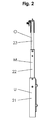
Figur 1 - Fig. 2
- eine Ansicht des erfindungsgemäßen Seitenteils von der Seite,
- Fig. 3
- eine Ansicht des erfindungsgemäßen Seitenteils von oben,
- Fig.3a
- ein Detail aus
Figur 3 in vergrößerter Darstellung, - Fig.4
- eine weitere Seitenansicht des erfindungsgemäßen Seitenteils von vorn,
- Fig.4a
- ein erstes Detail aus
Figur 4 in vergrößerter Darstellung, - Fig.4b
- ein zweites Detail aus
Figur 4 in vergrößerter Darstellung, - Fig.5
- einen vertikalen Schnitt durch das Seitenteil,
- Fig.6
- eine perspektivische Darstellung des Seitenteils,
- Fig.6a
- ein erstes Detail aus
Figur 6 in vergrößerter Darstellung, - Fig.6b
- ein zweites Detail aus
Figur 6 in vergrößerter Darstellung, - Fig.6c
- ein drittes Detail aus
Figur 6 in vergrößerter Darstellung.
- Fig. 1
- a view of a side part according to the invention from the front,
- Fig. 1a
- a horizontal section along the line la-la in
FIG. 1 in an enlarged view, - Fig. 1b
- a horizontal section along the line Ib-Ib in
FIG. 1 in an enlarged view, - Fig. 1c
- a horizontal section along the line Ic-Ic in
FIG. 1 in an enlarged view, - Fig. 2
- a view of the side part according to the invention from the side,
- Fig. 3
- a view of the side part according to the invention from above,
- 3a
- a detail from
FIG. 3 in an enlarged view, - Figure 4
- another side view of the side part according to the invention from the front,
- 4a
- a first detail
FIG. 4 in an enlarged view, - 4b
- a second detail
FIG. 4 in an enlarged view, - Figure 5
- a vertical section through the side part,
- Figure 6
- a perspective view of the side part,
- 6a
- a first detail
FIG. 6 in an enlarged view, - Figure 6b
- a second detail
FIG. 6 in an enlarged view, - 6C
- a third detail
FIG. 6 in an enlarged view.
Die in den Figuren dargestellten erfindungsgemäßen Seitenteile umfassen ein unteres Teil U als erstes Teil, ein mittleres Teil M als zweites Teil und ein oberes Teil O als drittes Teil. Das untere Teil U, das mittlere Teil M und das obere Teil O sind ausziehbar und einschiebbar miteinander verbunden.The side parts according to the invention shown in the figures comprise a lower part U as a first part, a middle part M as a second part and an upper part O as a third part. The lower part U, the middle part M and the upper part O are extendable and insertable connected to each other.
Das untere Teil U umfasst ein erstes Pfostenteil 11 eines ersten Pfostens 10 und ein erstes Pfostenteil 21 eines zweiten Pfostens 20.The lower part U comprises a first post part 11 of a first post 10 and a
Das mittlere Teil M umfasst ein zweites Pfostenteil 12 des ersten Pfostens 10, einen ersten Holm 31, einen zweiten Holm 32 und ein zweites Pfostenteil 22 des zweiten Pfostens 20. Die beiden zweiten Pfostenteile 12, 22 sind miteinander fest verbunden, und zwar über den ersten Holm 3 und den zweiten Holm 32.The middle part M comprises a second post part 12 of the first post 10, a
In entsprechender Art und Weise ist das obere Teil O ausgebildet. Es umfasst ein drittes Pfostenteil 13 des ersten Pfostens 10, einen dritten Holm 33 und ein drittes Pfostenteil 23 des zweiten Pfostens 2. Der Holm 33 verbindet das dritte Pfostenteil 13 des ersten Pfostens 10 und das dritte Pfostenteil 23 des zweiten Pfostens 20 starr miteinander.In a corresponding manner, the upper part O is formed. It comprises a third post part 13 of the first post 10, a
Das erste Pfostenteil 11, das zweite Pfostenteil 12 und das dritte Pfostenteil 13 des ersten Pfostens 10 sind teleskopartig ausziehbar ebenso wie das erste Pfostenteil 21, das zweite Pfostenteil 22 und das dritte Pfostenteil 23 des zweiten Pfostens 20. Das erste Pfostenteil 11, 21, das zweite Pfostenteil 12, 22 und das dritte Pfostenteil 13, 23 des ersten und des zweiten Pfostens 10, 20 werden durch Hohlprofil gebildet, von denen das erste Pfostenteil den größten Querschnitt und das dritte Pfostenteil den kleinsten Querschnitt hat (
Die Ausbildung der Pfostenteile des ersten Pfostens 10 und des zweiten Pfostens 20 entspricht im Wesentlichen den in der Druckschrift
Das erste Teil U, das zweite Teil M und das dritte Teil O können in unterschiedlichen Positionen zueinander fixiert werden. Die Teile U, M, O können vollständig in einander geschobenen oder vollständig ausgezogen sein. Es können auch Zwischenpositionen eingenommen werden. Es sind Haltemittel 61, 62 vorgesehen, mit denen die Pfostenteile 11, 12, 13, 21, 22, 23 in den unterschiedlichen Positionen gegeneinander verriegelt werden können. Über Lösemittel 63, 64 können diese Haltemittel 61 ,62 gelöst werden, falls das Seitenteil weiter ausgezogenen oder weiter in einander geschobenen werden soll. Auch insoweit entspricht das Seitenteil dem in der Druckschrift
Im Hinblick auf den Auslösemechanismus zum Lösen der Haltemittel 61, 62 besteht allerdings ein Unterschied zwischen dem bekannten Seitenteil und der erfindungsgemäßen Seitenteile, der darin begründet ist, dass das erfindungsgemäße Seitenteil länger ist als das Vorbekannte. Damit auch bei einem verlängerten Seitenteil eine Person mit beiden Händen gleichzeitig sowohl die Haltemittel im ersten Pfosten 10 als auch die Haltemittel 61, 62 im zweiten Pfosten 20 auslösen kann, sind Auslösertasten 65 vorgesehen, die nicht an den Pfosten 10, 20 sondern von den Pfosten 10, 20 nach innen versetzt an dem dritten Holm 33 angebracht sind.With regard to the release mechanism for releasing the retaining means 61, 62, however, there is a difference between the known side part and the side parts according to the invention, which is due to the fact that the side part according to the invention is longer than the previously known. In order for a person with both hands at the same time trigger both the holding means in the first post 10 and the holding means 61, 62 in the second post 20 even with an extended side panel,
Die Auslösertasten 65 wirken mit je einem schwenkbaren Hebel 66 zusammen, der schwenkbar an dem dritten Holm 33 angebracht ist. Die schwenkbaren Hebel 66 weisen dazu einen Schwenkabschnitt 661 auf, von dem sich zum einen ein Abschnitt zu der Auslösertaste 65 erstreckt und zum anderen ein Abschnitt zu einer Auslöserstange 63 erstreckt. Die schwenkbaren Hebel 66 sind dabei so geformt, dass bei einem Druck auf die Auslösertasten 65 die Auslöserstangen 63 angehobenen werden, um insbesondere das Haltemittel 61 zu lösen.The
Das Wesentliche neue des erfindungsgemäßen Seitenteils ist allerdings, das eine Bewegungskopplung zwischen dem ersten und dem zweiten Pfostenteil 11, 12 des ersten Pfostens 10 einerseits und dem ersten und dem zweiten Pfostenteil 21, 22 des zweiten Pfostens 20 andererseits und außerdem zwischen dem zweiten und dem dritten Pfostenteil 12, 13 des ersten Pfostens 10 einerseits und dem zweiten und dem dritten Pfostenteil 22, 23 des zweiten Pfostens 20 andererseits vorgesehen ist. Diese Kopplungen ermöglichen ein leichtgängiges Verschieben des zweiten Teils M zum ersten Teil U und des dritten Teils O zum zweiten Teil M.The essential new of the side part according to the invention, however, is a movement coupling between the first and the second post part 11, 12 of the first post 10 on the one hand and the first and the
Die Bewegungskopplung wird durch ein erstes Bewegungsübertragungsmittel 40 und ein zweites Bewegungsübertragungsmittel 50 erreicht.The motion coupling is achieved by a first motion transmission means 40 and a second motion transmission means 50.
Das erste Bewegungsübertragungsmittel 40 umfasst eine Welle 41. Die Welle ist zwischen dem ersten Pfosten 10 und dem zweiten Pfosten 20 genauer gesagt zwischen den zweiten Pfostenteilen 12, 22 des ersten Pfostens 10 und des zweiten Pfostens 20 in dem ersten Holm 31 gelagert. An den Enden der Welle 41 sind Zahnräder 42 angebracht. Die Zahnräder 42 greifen in Zahnstangen 43 ein, die an den ersten Pfostenteilen 11, 21 angebracht sind. Wird nun das zweite Pfostenteil 12, 22 eines der beiden Pfosten 10, 20 gegenüber dem ersten Pfostenteil 11, 21 des selben Pfostens 10, 20 verschoben, bewirkt diese Verschiebung eine Drehung der Welle 41. Über die Welle 41 wird dann die Bewegung auf den anderen Pfosten 20, 10 übertragen. Das Zahnrad 42 an dem anderen Pfosten 20, 10 rollt in der Zahnstange am ersten Pfostenteil 21, 11 des anderen Pfostens 20, 10 ab und überträgt so die Bewegung von dem einen auf den anderen Pfosten. Damit ist ein leichtgängiges Verschieben des zweiten Teils M gegenüber dem ersten Teil U möglich.The first movement transmission means 40 comprises a
Das zweite Bewegungsübertragungsmittel 50, dass die Bewegung zwischen dem zweiten Teil M und dem dritten Teil O koppelt, weist zwei Zugglieder 51, 52 auf. Das erste Zugglied 51 und das zweite Zugglied 52 (siehe
Über das erste Zugglied 51 ist somit das obere Ende des dritten Pfostenteils 13 des ersten Pfostens 10 kinematisch mit dem unteren Ende des dritten Pfostenteils 23 des zweiten Pfostens 20 gekoppelt. Eine Bewegung des einen Pfostenteils wird also auf das andere Pfostenteil übertragen. Über das zweite Zugglied 52 ist das obere Ende des dritten Pfostenteils 23 des zweiten Pfostens 20 kinematisch mit dem unteren Ende des dritten Pfostenteils 13 des ersten Pfostens 10 gekoppelt. Auch hier wird durch das Zugglied 52 die Bewegung des einen Pfostenteils auf das andere Pfostenteil übertragen. Durch diese kinematische Kopplung der Pfostenteile wird ein leichtgängiges Verschieben des dritten Teils O gegenüber dem zweiten Teil M möglich.Thus, the upper end of the third post part 13 of the first post 10 is kinematically coupled to the lower end of the
Claims (15)
die Anordnung wenigstens ein erstes Bewegungsübertragungsmittel (40) aufweist,
the arrangement has at least one first motion transmission means (40),
die Seitenteile, das Kopfteil und/oder das Fußteil durch eine Anordnung nach einem der Ansprüche 1 bis 13 gebildet ist.Bed, in particular hospital or nursing bed, with partially lowerable side and / or head or foot parts, having the following features:
the side parts, the head part and / or the foot part is formed by an arrangement according to one of claims 1 to 13.
Priority Applications (3)
| Application Number | Priority Date | Filing Date | Title |
|---|---|---|---|
| DK09163140.8T DK2263632T3 (en) | 2009-06-18 | 2009-06-18 | Device forming a side part, headboard or foot on a bed with a moving transfer means and bed with such a device |
| AT09163140T ATE532492T1 (en) | 2009-06-18 | 2009-06-18 | ARRANGEMENT FORMING A SIDE, HEAD OR FOOT PART OF A BED WITH A MOTION TRANSMISSION MEANS AND BED HAVING SUCH AN ARRANGEMENT |
| EP09163140A EP2263632B1 (en) | 2009-06-18 | 2009-06-18 | Assembly forming the side, head and foot parts of a bed with a movement transfer means and bed with such an assembly |
Applications Claiming Priority (1)
| Application Number | Priority Date | Filing Date | Title |
|---|---|---|---|
| EP09163140A EP2263632B1 (en) | 2009-06-18 | 2009-06-18 | Assembly forming the side, head and foot parts of a bed with a movement transfer means and bed with such an assembly |
Publications (2)
| Publication Number | Publication Date |
|---|---|
| EP2263632A1 true EP2263632A1 (en) | 2010-12-22 |
| EP2263632B1 EP2263632B1 (en) | 2011-11-09 |
Family
ID=41328635
Family Applications (1)
| Application Number | Title | Priority Date | Filing Date |
|---|---|---|---|
| EP09163140A Active EP2263632B1 (en) | 2009-06-18 | 2009-06-18 | Assembly forming the side, head and foot parts of a bed with a movement transfer means and bed with such an assembly |
Country Status (3)
| Country | Link |
|---|---|
| EP (1) | EP2263632B1 (en) |
| AT (1) | ATE532492T1 (en) |
| DK (1) | DK2263632T3 (en) |
Cited By (7)
| Publication number | Priority date | Publication date | Assignee | Title |
|---|---|---|---|---|
| DE202013004672U1 (en) | 2013-04-22 | 2013-06-17 | Embru-Werke Ag | Page grating device |
| WO2016008475A1 (en) * | 2014-07-16 | 2016-01-21 | Joh. Stiegelmeyer Gmbh & Co. Kg | Side-rail arrangement with synchronism |
| DE202015105365U1 (en) | 2015-10-09 | 2017-01-11 | Wissner-Bosserhoff Gmbh | Device for locking an extendable side part of a bed |
| DE202015105367U1 (en) | 2015-10-09 | 2017-01-11 | Wissner-Bosserhoff Gmbh | Bed with a device for locking an extendable side part of the bed |
| DE202016107514U1 (en) | 2016-12-30 | 2018-04-05 | Wissner-Bosserhoff Gmbh | Arrangement for securing a bed occupant against falling out of a bed, in particular a nursing bed, and bed, in particular nursing bed with a safety device |
| FR3067927A1 (en) * | 2017-06-26 | 2018-12-28 | Winncare France | TELESCOPIC AMOUNT OF BED BARRIER AND MEDICAL BED COMPRISING SUCH A BARRIER |
| IT201700111025A1 (en) * | 2017-10-04 | 2019-04-04 | Favero Health Projects Spa | LAYOUT STRUCTURE FOR BED |
Citations (3)
| Publication number | Priority date | Publication date | Assignee | Title |
|---|---|---|---|---|
| EP1243207A1 (en) * | 2001-03-22 | 2002-09-25 | Wissner-Bosserhoff GmbH | Hospital bed |
| US20060090260A1 (en) * | 2004-10-18 | 2006-05-04 | Stryker Martin W | Bed siderail |
| EP2052707A1 (en) | 2007-10-26 | 2009-04-29 | Wissner-Bosserhoff GmbH | Bed, in particular a hospital or home care bed with partially lowerable sides and/or head- and footboards |
-
2009
- 2009-06-18 EP EP09163140A patent/EP2263632B1/en active Active
- 2009-06-18 AT AT09163140T patent/ATE532492T1/en active
- 2009-06-18 DK DK09163140.8T patent/DK2263632T3/en active
Patent Citations (3)
| Publication number | Priority date | Publication date | Assignee | Title |
|---|---|---|---|---|
| EP1243207A1 (en) * | 2001-03-22 | 2002-09-25 | Wissner-Bosserhoff GmbH | Hospital bed |
| US20060090260A1 (en) * | 2004-10-18 | 2006-05-04 | Stryker Martin W | Bed siderail |
| EP2052707A1 (en) | 2007-10-26 | 2009-04-29 | Wissner-Bosserhoff GmbH | Bed, in particular a hospital or home care bed with partially lowerable sides and/or head- and footboards |
Cited By (9)
| Publication number | Priority date | Publication date | Assignee | Title |
|---|---|---|---|---|
| DE202013004672U1 (en) | 2013-04-22 | 2013-06-17 | Embru-Werke Ag | Page grating device |
| WO2016008475A1 (en) * | 2014-07-16 | 2016-01-21 | Joh. Stiegelmeyer Gmbh & Co. Kg | Side-rail arrangement with synchronism |
| DE202015105365U1 (en) | 2015-10-09 | 2017-01-11 | Wissner-Bosserhoff Gmbh | Device for locking an extendable side part of a bed |
| DE202015105367U1 (en) | 2015-10-09 | 2017-01-11 | Wissner-Bosserhoff Gmbh | Bed with a device for locking an extendable side part of the bed |
| DE202016107514U1 (en) | 2016-12-30 | 2018-04-05 | Wissner-Bosserhoff Gmbh | Arrangement for securing a bed occupant against falling out of a bed, in particular a nursing bed, and bed, in particular nursing bed with a safety device |
| EP3342387A3 (en) * | 2016-12-30 | 2018-11-14 | Wissner-Bosserhoff GmbH | Bed, in particular nursing bed with a safety assembly and assembly for securing a bed occupant against falling out of a bed, in particular a nursing bed. |
| FR3067927A1 (en) * | 2017-06-26 | 2018-12-28 | Winncare France | TELESCOPIC AMOUNT OF BED BARRIER AND MEDICAL BED COMPRISING SUCH A BARRIER |
| EP3421024A1 (en) | 2017-06-26 | 2019-01-02 | Winncare France | Telescopic post of bed barrier and hospital bed comprising such a barrier |
| IT201700111025A1 (en) * | 2017-10-04 | 2019-04-04 | Favero Health Projects Spa | LAYOUT STRUCTURE FOR BED |
Also Published As
| Publication number | Publication date |
|---|---|
| DK2263632T3 (en) | 2012-02-27 |
| EP2263632B1 (en) | 2011-11-09 |
| ATE532492T1 (en) | 2011-11-15 |
Similar Documents
| Publication | Publication Date | Title |
|---|---|---|
| EP2263632B1 (en) | Assembly forming the side, head and foot parts of a bed with a movement transfer means and bed with such an assembly | |
| EP0017765B1 (en) | Hydraulic lifting device | |
| WO2015192153A1 (en) | Drive mechanism for a movable furniture part | |
| EP1523257A1 (en) | Adjusting device and adjustable support device for beds, mattresses, armchairs and the like | |
| EP3009052B1 (en) | Retrofit kit for retrofitting a supporting device | |
| EP2878230A1 (en) | Positioning lever mechanism with Bowden cable assembly | |
| EP1810596B1 (en) | Sequential drawer slide or the like | |
| EP3342387B1 (en) | Bed, in particular nursing bed with a safety assembly and assembly for securing a bed occupant against falling out of a bed, in particular a nursing bed. | |
| AT516222B1 (en) | pull-out | |
| EP3169295B1 (en) | Side-rail arrangement with synchronism | |
| DE19707799B4 (en) | Work scaffold with raised and lowered boom | |
| EP3659467B1 (en) | Height-adjustable device | |
| DE202010000060U1 (en) | Functional table with braking device | |
| DE102015207351B4 (en) | Height-adjustable table frame and table | |
| EP1543744B1 (en) | Lifting device for beds | |
| DE20211072U1 (en) | Lying unit | |
| DE102014115084A1 (en) | furniture drive | |
| DE19752234A1 (en) | Drive device for reversible pivot movement | |
| DE2746031C3 (en) | Coupling harness for a lemniscate shield support frame | |
| DE102013002003B4 (en) | Adjusting device for adjusting the height of a table or worktop of a piece of furniture | |
| EP0792670A1 (en) | Hurdle for use in athletics | |
| EP0853172B1 (en) | Sun protecting arrangement | |
| AT402780B (en) | SEAT- OR LOUNGE FURNITURE | |
| DE2224803C3 (en) | ||
| DE102016201315B4 (en) | care bed |
Legal Events
| Date | Code | Title | Description |
|---|---|---|---|
| PUAI | Public reference made under article 153(3) epc to a published international application that has entered the european phase |
Free format text: ORIGINAL CODE: 0009012 |
|
| 17P | Request for examination filed |
Effective date: 20100517 |
|
| AK | Designated contracting states |
Kind code of ref document: A1 Designated state(s): AT BE BG CH CY CZ DE DK EE ES FI FR GB GR HR HU IE IS IT LI LT LU LV MC MK MT NL NO PL PT RO SE SI SK TR |
|
| AX | Request for extension of the european patent |
Extension state: AL BA RS |
|
| RIC1 | Information provided on ipc code assigned before grant |
Ipc: A61G 7/05 20060101AFI20110121BHEP |
|
| GRAP | Despatch of communication of intention to grant a patent |
Free format text: ORIGINAL CODE: EPIDOSNIGR1 |
|
| GRAS | Grant fee paid |
Free format text: ORIGINAL CODE: EPIDOSNIGR3 |
|
| GRAA | (expected) grant |
Free format text: ORIGINAL CODE: 0009210 |
|
| AK | Designated contracting states |
Kind code of ref document: B1 Designated state(s): AT BE BG CH CY CZ DE DK EE ES FI FR GB GR HR HU IE IS IT LI LT LU LV MC MK MT NL NO PL PT RO SE SI SK TR |
|
| REG | Reference to a national code |
Ref country code: GB Ref legal event code: FG4D Free format text: NOT ENGLISH |
|
| REG | Reference to a national code |
Ref country code: CH Ref legal event code: EP |
|
| REG | Reference to a national code |
Ref country code: IE Ref legal event code: FG4D Free format text: LANGUAGE OF EP DOCUMENT: GERMAN |
|
| REG | Reference to a national code |
Ref country code: DE Ref legal event code: R096 Ref document number: 502009001870 Country of ref document: DE Effective date: 20120209 |
|
| REG | Reference to a national code |
Ref country code: NL Ref legal event code: T3 |
|
| REG | Reference to a national code |
Ref country code: DK Ref legal event code: T3 |
|
| REG | Reference to a national code |
Ref country code: SE Ref legal event code: TRGR |
|
| REG | Reference to a national code |
Ref country code: ES Ref legal event code: FG2A Ref document number: 2377432 Country of ref document: ES Kind code of ref document: T3 Effective date: 20120327 |
|
| LTIE | Lt: invalidation of european patent or patent extension |
Effective date: 20111109 |
|
| PG25 | Lapsed in a contracting state [announced via postgrant information from national office to epo] |
Ref country code: LT Free format text: LAPSE BECAUSE OF FAILURE TO SUBMIT A TRANSLATION OF THE DESCRIPTION OR TO PAY THE FEE WITHIN THE PRESCRIBED TIME-LIMIT Effective date: 20111109 Ref country code: NO Free format text: LAPSE BECAUSE OF FAILURE TO SUBMIT A TRANSLATION OF THE DESCRIPTION OR TO PAY THE FEE WITHIN THE PRESCRIBED TIME-LIMIT Effective date: 20120209 Ref country code: IS Free format text: LAPSE BECAUSE OF FAILURE TO SUBMIT A TRANSLATION OF THE DESCRIPTION OR TO PAY THE FEE WITHIN THE PRESCRIBED TIME-LIMIT Effective date: 20120309 |
|
| PG25 | Lapsed in a contracting state [announced via postgrant information from national office to epo] |
Ref country code: SI Free format text: LAPSE BECAUSE OF FAILURE TO SUBMIT A TRANSLATION OF THE DESCRIPTION OR TO PAY THE FEE WITHIN THE PRESCRIBED TIME-LIMIT Effective date: 20111109 Ref country code: PL Free format text: LAPSE BECAUSE OF FAILURE TO SUBMIT A TRANSLATION OF THE DESCRIPTION OR TO PAY THE FEE WITHIN THE PRESCRIBED TIME-LIMIT Effective date: 20111109 Ref country code: PT Free format text: LAPSE BECAUSE OF FAILURE TO SUBMIT A TRANSLATION OF THE DESCRIPTION OR TO PAY THE FEE WITHIN THE PRESCRIBED TIME-LIMIT Effective date: 20120309 Ref country code: HR Free format text: LAPSE BECAUSE OF FAILURE TO SUBMIT A TRANSLATION OF THE DESCRIPTION OR TO PAY THE FEE WITHIN THE PRESCRIBED TIME-LIMIT Effective date: 20111109 Ref country code: LV Free format text: LAPSE BECAUSE OF FAILURE TO SUBMIT A TRANSLATION OF THE DESCRIPTION OR TO PAY THE FEE WITHIN THE PRESCRIBED TIME-LIMIT Effective date: 20111109 Ref country code: GR Free format text: LAPSE BECAUSE OF FAILURE TO SUBMIT A TRANSLATION OF THE DESCRIPTION OR TO PAY THE FEE WITHIN THE PRESCRIBED TIME-LIMIT Effective date: 20120210 |
|
| REG | Reference to a national code |
Ref country code: IE Ref legal event code: FD4D |
|
| PG25 | Lapsed in a contracting state [announced via postgrant information from national office to epo] |
Ref country code: CY Free format text: LAPSE BECAUSE OF FAILURE TO SUBMIT A TRANSLATION OF THE DESCRIPTION OR TO PAY THE FEE WITHIN THE PRESCRIBED TIME-LIMIT Effective date: 20111109 |
|
| PG25 | Lapsed in a contracting state [announced via postgrant information from national office to epo] |
Ref country code: BG Free format text: LAPSE BECAUSE OF FAILURE TO SUBMIT A TRANSLATION OF THE DESCRIPTION OR TO PAY THE FEE WITHIN THE PRESCRIBED TIME-LIMIT Effective date: 20120209 Ref country code: IE Free format text: LAPSE BECAUSE OF FAILURE TO SUBMIT A TRANSLATION OF THE DESCRIPTION OR TO PAY THE FEE WITHIN THE PRESCRIBED TIME-LIMIT Effective date: 20111109 Ref country code: SK Free format text: LAPSE BECAUSE OF FAILURE TO SUBMIT A TRANSLATION OF THE DESCRIPTION OR TO PAY THE FEE WITHIN THE PRESCRIBED TIME-LIMIT Effective date: 20111109 Ref country code: EE Free format text: LAPSE BECAUSE OF FAILURE TO SUBMIT A TRANSLATION OF THE DESCRIPTION OR TO PAY THE FEE WITHIN THE PRESCRIBED TIME-LIMIT Effective date: 20111109 |
|
| PG25 | Lapsed in a contracting state [announced via postgrant information from national office to epo] |
Ref country code: RO Free format text: LAPSE BECAUSE OF FAILURE TO SUBMIT A TRANSLATION OF THE DESCRIPTION OR TO PAY THE FEE WITHIN THE PRESCRIBED TIME-LIMIT Effective date: 20111109 |
|
| PLBE | No opposition filed within time limit |
Free format text: ORIGINAL CODE: 0009261 |
|
| STAA | Information on the status of an ep patent application or granted ep patent |
Free format text: STATUS: NO OPPOSITION FILED WITHIN TIME LIMIT |
|
| 26N | No opposition filed |
Effective date: 20120810 |
|
| REG | Reference to a national code |
Ref country code: DE Ref legal event code: R097 Ref document number: 502009001870 Country of ref document: DE Effective date: 20120810 |
|
| PG25 | Lapsed in a contracting state [announced via postgrant information from national office to epo] |
Ref country code: MC Free format text: LAPSE BECAUSE OF NON-PAYMENT OF DUE FEES Effective date: 20120630 |
|
| PG25 | Lapsed in a contracting state [announced via postgrant information from national office to epo] |
Ref country code: MK Free format text: LAPSE BECAUSE OF FAILURE TO SUBMIT A TRANSLATION OF THE DESCRIPTION OR TO PAY THE FEE WITHIN THE PRESCRIBED TIME-LIMIT Effective date: 20111109 |
|
| PG25 | Lapsed in a contracting state [announced via postgrant information from national office to epo] |
Ref country code: FI Free format text: LAPSE BECAUSE OF FAILURE TO SUBMIT A TRANSLATION OF THE DESCRIPTION OR TO PAY THE FEE WITHIN THE PRESCRIBED TIME-LIMIT Effective date: 20111109 |
|
| PG25 | Lapsed in a contracting state [announced via postgrant information from national office to epo] |
Ref country code: MT Free format text: LAPSE BECAUSE OF FAILURE TO SUBMIT A TRANSLATION OF THE DESCRIPTION OR TO PAY THE FEE WITHIN THE PRESCRIBED TIME-LIMIT Effective date: 20111109 |
|
| PG25 | Lapsed in a contracting state [announced via postgrant information from national office to epo] |
Ref country code: LU Free format text: LAPSE BECAUSE OF NON-PAYMENT OF DUE FEES Effective date: 20120618 |
|
| PG25 | Lapsed in a contracting state [announced via postgrant information from national office to epo] |
Ref country code: HU Free format text: LAPSE BECAUSE OF FAILURE TO SUBMIT A TRANSLATION OF THE DESCRIPTION OR TO PAY THE FEE WITHIN THE PRESCRIBED TIME-LIMIT Effective date: 20090618 |
|
| REG | Reference to a national code |
Ref country code: FR Ref legal event code: PLFP Year of fee payment: 8 |
|
| PGFP | Annual fee paid to national office [announced via postgrant information from national office to epo] |
Ref country code: CZ Payment date: 20160525 Year of fee payment: 8 Ref country code: GB Payment date: 20160621 Year of fee payment: 8 Ref country code: CH Payment date: 20160620 Year of fee payment: 8 Ref country code: ES Payment date: 20160614 Year of fee payment: 8 |
|
| PGFP | Annual fee paid to national office [announced via postgrant information from national office to epo] |
Ref country code: SE Payment date: 20160620 Year of fee payment: 8 Ref country code: DK Payment date: 20160620 Year of fee payment: 8 Ref country code: NL Payment date: 20160620 Year of fee payment: 8 Ref country code: BE Payment date: 20160620 Year of fee payment: 8 Ref country code: TR Payment date: 20160527 Year of fee payment: 8 |
|
| PGFP | Annual fee paid to national office [announced via postgrant information from national office to epo] |
Ref country code: IT Payment date: 20160627 Year of fee payment: 8 |
|
| REG | Reference to a national code |
Ref country code: FR Ref legal event code: PLFP Year of fee payment: 9 |
|
| REG | Reference to a national code |
Ref country code: DK Ref legal event code: EBP Effective date: 20170630 |
|
| REG | Reference to a national code |
Ref country code: SE Ref legal event code: EUG |
|
| PG25 | Lapsed in a contracting state [announced via postgrant information from national office to epo] |
Ref country code: CZ Free format text: LAPSE BECAUSE OF NON-PAYMENT OF DUE FEES Effective date: 20170618 |
|
| REG | Reference to a national code |
Ref country code: CH Ref legal event code: PL |
|
| REG | Reference to a national code |
Ref country code: NL Ref legal event code: MM Effective date: 20170701 |
|
| GBPC | Gb: european patent ceased through non-payment of renewal fee |
Effective date: 20170618 |
|
| PG25 | Lapsed in a contracting state [announced via postgrant information from national office to epo] |
Ref country code: SE Free format text: LAPSE BECAUSE OF NON-PAYMENT OF DUE FEES Effective date: 20170619 |
|
| PG25 | Lapsed in a contracting state [announced via postgrant information from national office to epo] |
Ref country code: NL Free format text: LAPSE BECAUSE OF NON-PAYMENT OF DUE FEES Effective date: 20170701 |
|
| PG25 | Lapsed in a contracting state [announced via postgrant information from national office to epo] |
Ref country code: LI Free format text: LAPSE BECAUSE OF NON-PAYMENT OF DUE FEES Effective date: 20170630 Ref country code: GB Free format text: LAPSE BECAUSE OF NON-PAYMENT OF DUE FEES Effective date: 20170618 Ref country code: CH Free format text: LAPSE BECAUSE OF NON-PAYMENT OF DUE FEES Effective date: 20170630 |
|
| REG | Reference to a national code |
Ref country code: BE Ref legal event code: MM Effective date: 20170630 |
|
| PG25 | Lapsed in a contracting state [announced via postgrant information from national office to epo] |
Ref country code: IT Free format text: LAPSE BECAUSE OF NON-PAYMENT OF DUE FEES Effective date: 20170618 |
|
| REG | Reference to a national code |
Ref country code: FR Ref legal event code: PLFP Year of fee payment: 10 |
|
| PG25 | Lapsed in a contracting state [announced via postgrant information from national office to epo] |
Ref country code: DK Free format text: LAPSE BECAUSE OF NON-PAYMENT OF DUE FEES Effective date: 20170630 |
|
| PG25 | Lapsed in a contracting state [announced via postgrant information from national office to epo] |
Ref country code: BE Free format text: LAPSE BECAUSE OF NON-PAYMENT OF DUE FEES Effective date: 20170630 |
|
| REG | Reference to a national code |
Ref country code: ES Ref legal event code: FD2A Effective date: 20181112 |
|
| PG25 | Lapsed in a contracting state [announced via postgrant information from national office to epo] |
Ref country code: ES Free format text: LAPSE BECAUSE OF NON-PAYMENT OF DUE FEES Effective date: 20170619 |
|
| PG25 | Lapsed in a contracting state [announced via postgrant information from national office to epo] |
Ref country code: TR Free format text: LAPSE BECAUSE OF NON-PAYMENT OF DUE FEES Effective date: 20170618 |
|
| P01 | Opt-out of the competence of the unified patent court (upc) registered |
Effective date: 20230616 |
|
| PGFP | Annual fee paid to national office [announced via postgrant information from national office to epo] |
Ref country code: FR Payment date: 20230620 Year of fee payment: 15 Ref country code: DE Payment date: 20230630 Year of fee payment: 15 |
|
| PGFP | Annual fee paid to national office [announced via postgrant information from national office to epo] |
Ref country code: AT Payment date: 20230621 Year of fee payment: 15 |