EP2263614A1 - Trapezo-metacarpal joint implant - Google Patents
Trapezo-metacarpal joint implant Download PDFInfo
- Publication number
- EP2263614A1 EP2263614A1 EP10166447A EP10166447A EP2263614A1 EP 2263614 A1 EP2263614 A1 EP 2263614A1 EP 10166447 A EP10166447 A EP 10166447A EP 10166447 A EP10166447 A EP 10166447A EP 2263614 A1 EP2263614 A1 EP 2263614A1
- Authority
- EP
- European Patent Office
- Prior art keywords
- metacarpal
- implant
- trapezial
- articular
- section
- Prior art date
- Legal status (The legal status is an assumption and is not a legal conclusion. Google has not performed a legal analysis and makes no representation as to the accuracy of the status listed.)
- Granted
Links
Images


Classifications
-
- A—HUMAN NECESSITIES
- A61—MEDICAL OR VETERINARY SCIENCE; HYGIENE
- A61F—FILTERS IMPLANTABLE INTO BLOOD VESSELS; PROSTHESES; DEVICES PROVIDING PATENCY TO, OR PREVENTING COLLAPSING OF, TUBULAR STRUCTURES OF THE BODY, e.g. STENTS; ORTHOPAEDIC, NURSING OR CONTRACEPTIVE DEVICES; FOMENTATION; TREATMENT OR PROTECTION OF EYES OR EARS; BANDAGES, DRESSINGS OR ABSORBENT PADS; FIRST-AID KITS
- A61F2/00—Filters implantable into blood vessels; Prostheses, i.e. artificial substitutes or replacements for parts of the body; Appliances for connecting them with the body; Devices providing patency to, or preventing collapsing of, tubular structures of the body, e.g. stents
- A61F2/02—Prostheses implantable into the body
- A61F2/30—Joints
- A61F2/42—Joints for wrists or ankles; for hands, e.g. fingers; for feet, e.g. toes
- A61F2/4261—Joints for wrists or ankles; for hands, e.g. fingers; for feet, e.g. toes for wrists
-
- A—HUMAN NECESSITIES
- A61—MEDICAL OR VETERINARY SCIENCE; HYGIENE
- A61F—FILTERS IMPLANTABLE INTO BLOOD VESSELS; PROSTHESES; DEVICES PROVIDING PATENCY TO, OR PREVENTING COLLAPSING OF, TUBULAR STRUCTURES OF THE BODY, e.g. STENTS; ORTHOPAEDIC, NURSING OR CONTRACEPTIVE DEVICES; FOMENTATION; TREATMENT OR PROTECTION OF EYES OR EARS; BANDAGES, DRESSINGS OR ABSORBENT PADS; FIRST-AID KITS
- A61F2/00—Filters implantable into blood vessels; Prostheses, i.e. artificial substitutes or replacements for parts of the body; Appliances for connecting them with the body; Devices providing patency to, or preventing collapsing of, tubular structures of the body, e.g. stents
- A61F2/02—Prostheses implantable into the body
- A61F2/30—Joints
- A61F2/42—Joints for wrists or ankles; for hands, e.g. fingers; for feet, e.g. toes
- A61F2/4241—Joints for wrists or ankles; for hands, e.g. fingers; for feet, e.g. toes for hands, e.g. fingers
-
- A—HUMAN NECESSITIES
- A61—MEDICAL OR VETERINARY SCIENCE; HYGIENE
- A61F—FILTERS IMPLANTABLE INTO BLOOD VESSELS; PROSTHESES; DEVICES PROVIDING PATENCY TO, OR PREVENTING COLLAPSING OF, TUBULAR STRUCTURES OF THE BODY, e.g. STENTS; ORTHOPAEDIC, NURSING OR CONTRACEPTIVE DEVICES; FOMENTATION; TREATMENT OR PROTECTION OF EYES OR EARS; BANDAGES, DRESSINGS OR ABSORBENT PADS; FIRST-AID KITS
- A61F2/00—Filters implantable into blood vessels; Prostheses, i.e. artificial substitutes or replacements for parts of the body; Appliances for connecting them with the body; Devices providing patency to, or preventing collapsing of, tubular structures of the body, e.g. stents
- A61F2/02—Prostheses implantable into the body
- A61F2/30—Joints
- A61F2002/30001—Additional features of subject-matter classified in A61F2/28, A61F2/30 and subgroups thereof
- A61F2002/30108—Shapes
- A61F2002/3011—Cross-sections or two-dimensional shapes
- A61F2002/30138—Convex polygonal shapes
- A61F2002/30153—Convex polygonal shapes rectangular
-
- A—HUMAN NECESSITIES
- A61—MEDICAL OR VETERINARY SCIENCE; HYGIENE
- A61F—FILTERS IMPLANTABLE INTO BLOOD VESSELS; PROSTHESES; DEVICES PROVIDING PATENCY TO, OR PREVENTING COLLAPSING OF, TUBULAR STRUCTURES OF THE BODY, e.g. STENTS; ORTHOPAEDIC, NURSING OR CONTRACEPTIVE DEVICES; FOMENTATION; TREATMENT OR PROTECTION OF EYES OR EARS; BANDAGES, DRESSINGS OR ABSORBENT PADS; FIRST-AID KITS
- A61F2/00—Filters implantable into blood vessels; Prostheses, i.e. artificial substitutes or replacements for parts of the body; Appliances for connecting them with the body; Devices providing patency to, or preventing collapsing of, tubular structures of the body, e.g. stents
- A61F2/02—Prostheses implantable into the body
- A61F2/30—Joints
- A61F2002/30001—Additional features of subject-matter classified in A61F2/28, A61F2/30 and subgroups thereof
- A61F2002/30108—Shapes
- A61F2002/30199—Three-dimensional shapes
- A61F2002/302—Three-dimensional shapes toroidal, e.g. rings
-
- A—HUMAN NECESSITIES
- A61—MEDICAL OR VETERINARY SCIENCE; HYGIENE
- A61F—FILTERS IMPLANTABLE INTO BLOOD VESSELS; PROSTHESES; DEVICES PROVIDING PATENCY TO, OR PREVENTING COLLAPSING OF, TUBULAR STRUCTURES OF THE BODY, e.g. STENTS; ORTHOPAEDIC, NURSING OR CONTRACEPTIVE DEVICES; FOMENTATION; TREATMENT OR PROTECTION OF EYES OR EARS; BANDAGES, DRESSINGS OR ABSORBENT PADS; FIRST-AID KITS
- A61F2/00—Filters implantable into blood vessels; Prostheses, i.e. artificial substitutes or replacements for parts of the body; Appliances for connecting them with the body; Devices providing patency to, or preventing collapsing of, tubular structures of the body, e.g. stents
- A61F2/02—Prostheses implantable into the body
- A61F2/30—Joints
- A61F2002/30001—Additional features of subject-matter classified in A61F2/28, A61F2/30 and subgroups thereof
- A61F2002/30108—Shapes
- A61F2002/30199—Three-dimensional shapes
- A61F2002/30205—Three-dimensional shapes conical
-
- A—HUMAN NECESSITIES
- A61—MEDICAL OR VETERINARY SCIENCE; HYGIENE
- A61F—FILTERS IMPLANTABLE INTO BLOOD VESSELS; PROSTHESES; DEVICES PROVIDING PATENCY TO, OR PREVENTING COLLAPSING OF, TUBULAR STRUCTURES OF THE BODY, e.g. STENTS; ORTHOPAEDIC, NURSING OR CONTRACEPTIVE DEVICES; FOMENTATION; TREATMENT OR PROTECTION OF EYES OR EARS; BANDAGES, DRESSINGS OR ABSORBENT PADS; FIRST-AID KITS
- A61F2/00—Filters implantable into blood vessels; Prostheses, i.e. artificial substitutes or replacements for parts of the body; Appliances for connecting them with the body; Devices providing patency to, or preventing collapsing of, tubular structures of the body, e.g. stents
- A61F2/02—Prostheses implantable into the body
- A61F2/30—Joints
- A61F2002/30001—Additional features of subject-matter classified in A61F2/28, A61F2/30 and subgroups thereof
- A61F2002/30108—Shapes
- A61F2002/30199—Three-dimensional shapes
- A61F2002/30224—Three-dimensional shapes cylindrical
-
- A—HUMAN NECESSITIES
- A61—MEDICAL OR VETERINARY SCIENCE; HYGIENE
- A61F—FILTERS IMPLANTABLE INTO BLOOD VESSELS; PROSTHESES; DEVICES PROVIDING PATENCY TO, OR PREVENTING COLLAPSING OF, TUBULAR STRUCTURES OF THE BODY, e.g. STENTS; ORTHOPAEDIC, NURSING OR CONTRACEPTIVE DEVICES; FOMENTATION; TREATMENT OR PROTECTION OF EYES OR EARS; BANDAGES, DRESSINGS OR ABSORBENT PADS; FIRST-AID KITS
- A61F2/00—Filters implantable into blood vessels; Prostheses, i.e. artificial substitutes or replacements for parts of the body; Appliances for connecting them with the body; Devices providing patency to, or preventing collapsing of, tubular structures of the body, e.g. stents
- A61F2/02—Prostheses implantable into the body
- A61F2/30—Joints
- A61F2002/30001—Additional features of subject-matter classified in A61F2/28, A61F2/30 and subgroups thereof
- A61F2002/30108—Shapes
- A61F2002/30199—Three-dimensional shapes
- A61F2002/30301—Three-dimensional shapes saddle-shaped
-
- A—HUMAN NECESSITIES
- A61—MEDICAL OR VETERINARY SCIENCE; HYGIENE
- A61F—FILTERS IMPLANTABLE INTO BLOOD VESSELS; PROSTHESES; DEVICES PROVIDING PATENCY TO, OR PREVENTING COLLAPSING OF, TUBULAR STRUCTURES OF THE BODY, e.g. STENTS; ORTHOPAEDIC, NURSING OR CONTRACEPTIVE DEVICES; FOMENTATION; TREATMENT OR PROTECTION OF EYES OR EARS; BANDAGES, DRESSINGS OR ABSORBENT PADS; FIRST-AID KITS
- A61F2/00—Filters implantable into blood vessels; Prostheses, i.e. artificial substitutes or replacements for parts of the body; Appliances for connecting them with the body; Devices providing patency to, or preventing collapsing of, tubular structures of the body, e.g. stents
- A61F2/02—Prostheses implantable into the body
- A61F2/30—Joints
- A61F2002/30001—Additional features of subject-matter classified in A61F2/28, A61F2/30 and subgroups thereof
- A61F2002/30316—The prosthesis having different structural features at different locations within the same prosthesis; Connections between prosthetic parts; Special structural features of bone or joint prostheses not otherwise provided for
- A61F2002/30535—Special structural features of bone or joint prostheses not otherwise provided for
- A61F2002/30604—Special structural features of bone or joint prostheses not otherwise provided for modular
- A61F2002/30616—Sets comprising a plurality of prosthetic parts of different sizes or orientations
-
- A—HUMAN NECESSITIES
- A61—MEDICAL OR VETERINARY SCIENCE; HYGIENE
- A61F—FILTERS IMPLANTABLE INTO BLOOD VESSELS; PROSTHESES; DEVICES PROVIDING PATENCY TO, OR PREVENTING COLLAPSING OF, TUBULAR STRUCTURES OF THE BODY, e.g. STENTS; ORTHOPAEDIC, NURSING OR CONTRACEPTIVE DEVICES; FOMENTATION; TREATMENT OR PROTECTION OF EYES OR EARS; BANDAGES, DRESSINGS OR ABSORBENT PADS; FIRST-AID KITS
- A61F2/00—Filters implantable into blood vessels; Prostheses, i.e. artificial substitutes or replacements for parts of the body; Appliances for connecting them with the body; Devices providing patency to, or preventing collapsing of, tubular structures of the body, e.g. stents
- A61F2/02—Prostheses implantable into the body
- A61F2/30—Joints
- A61F2/30721—Accessories
- A61F2002/30754—Implants for interposition between two natural articular surfaces
-
- A—HUMAN NECESSITIES
- A61—MEDICAL OR VETERINARY SCIENCE; HYGIENE
- A61F—FILTERS IMPLANTABLE INTO BLOOD VESSELS; PROSTHESES; DEVICES PROVIDING PATENCY TO, OR PREVENTING COLLAPSING OF, TUBULAR STRUCTURES OF THE BODY, e.g. STENTS; ORTHOPAEDIC, NURSING OR CONTRACEPTIVE DEVICES; FOMENTATION; TREATMENT OR PROTECTION OF EYES OR EARS; BANDAGES, DRESSINGS OR ABSORBENT PADS; FIRST-AID KITS
- A61F2/00—Filters implantable into blood vessels; Prostheses, i.e. artificial substitutes or replacements for parts of the body; Appliances for connecting them with the body; Devices providing patency to, or preventing collapsing of, tubular structures of the body, e.g. stents
- A61F2/02—Prostheses implantable into the body
- A61F2/30—Joints
- A61F2/42—Joints for wrists or ankles; for hands, e.g. fingers; for feet, e.g. toes
- A61F2/4241—Joints for wrists or ankles; for hands, e.g. fingers; for feet, e.g. toes for hands, e.g. fingers
- A61F2002/4256—Joints for wrists or ankles; for hands, e.g. fingers; for feet, e.g. toes for hands, e.g. fingers for carpo-metacarpal joints, i.e. CMC joints
- A61F2002/4258—Joints for wrists or ankles; for hands, e.g. fingers; for feet, e.g. toes for hands, e.g. fingers for carpo-metacarpal joints, i.e. CMC joints for trapezo-metacarpal joints of thumbs
-
- A—HUMAN NECESSITIES
- A61—MEDICAL OR VETERINARY SCIENCE; HYGIENE
- A61F—FILTERS IMPLANTABLE INTO BLOOD VESSELS; PROSTHESES; DEVICES PROVIDING PATENCY TO, OR PREVENTING COLLAPSING OF, TUBULAR STRUCTURES OF THE BODY, e.g. STENTS; ORTHOPAEDIC, NURSING OR CONTRACEPTIVE DEVICES; FOMENTATION; TREATMENT OR PROTECTION OF EYES OR EARS; BANDAGES, DRESSINGS OR ABSORBENT PADS; FIRST-AID KITS
- A61F2230/00—Geometry of prostheses classified in groups A61F2/00 - A61F2/26 or A61F2/82 or A61F9/00 or A61F11/00 or subgroups thereof
- A61F2230/0002—Two-dimensional shapes, e.g. cross-sections
- A61F2230/0017—Angular shapes
- A61F2230/0019—Angular shapes rectangular
-
- A—HUMAN NECESSITIES
- A61—MEDICAL OR VETERINARY SCIENCE; HYGIENE
- A61F—FILTERS IMPLANTABLE INTO BLOOD VESSELS; PROSTHESES; DEVICES PROVIDING PATENCY TO, OR PREVENTING COLLAPSING OF, TUBULAR STRUCTURES OF THE BODY, e.g. STENTS; ORTHOPAEDIC, NURSING OR CONTRACEPTIVE DEVICES; FOMENTATION; TREATMENT OR PROTECTION OF EYES OR EARS; BANDAGES, DRESSINGS OR ABSORBENT PADS; FIRST-AID KITS
- A61F2230/00—Geometry of prostheses classified in groups A61F2/00 - A61F2/26 or A61F2/82 or A61F9/00 or A61F11/00 or subgroups thereof
- A61F2230/0063—Three-dimensional shapes
- A61F2230/0065—Three-dimensional shapes toroidal, e.g. ring-shaped, doughnut-shaped
-
- A—HUMAN NECESSITIES
- A61—MEDICAL OR VETERINARY SCIENCE; HYGIENE
- A61F—FILTERS IMPLANTABLE INTO BLOOD VESSELS; PROSTHESES; DEVICES PROVIDING PATENCY TO, OR PREVENTING COLLAPSING OF, TUBULAR STRUCTURES OF THE BODY, e.g. STENTS; ORTHOPAEDIC, NURSING OR CONTRACEPTIVE DEVICES; FOMENTATION; TREATMENT OR PROTECTION OF EYES OR EARS; BANDAGES, DRESSINGS OR ABSORBENT PADS; FIRST-AID KITS
- A61F2230/00—Geometry of prostheses classified in groups A61F2/00 - A61F2/26 or A61F2/82 or A61F9/00 or A61F11/00 or subgroups thereof
- A61F2230/0063—Three-dimensional shapes
- A61F2230/0067—Three-dimensional shapes conical
-
- A—HUMAN NECESSITIES
- A61—MEDICAL OR VETERINARY SCIENCE; HYGIENE
- A61F—FILTERS IMPLANTABLE INTO BLOOD VESSELS; PROSTHESES; DEVICES PROVIDING PATENCY TO, OR PREVENTING COLLAPSING OF, TUBULAR STRUCTURES OF THE BODY, e.g. STENTS; ORTHOPAEDIC, NURSING OR CONTRACEPTIVE DEVICES; FOMENTATION; TREATMENT OR PROTECTION OF EYES OR EARS; BANDAGES, DRESSINGS OR ABSORBENT PADS; FIRST-AID KITS
- A61F2230/00—Geometry of prostheses classified in groups A61F2/00 - A61F2/26 or A61F2/82 or A61F9/00 or A61F11/00 or subgroups thereof
- A61F2230/0063—Three-dimensional shapes
- A61F2230/0069—Three-dimensional shapes cylindrical
-
- A—HUMAN NECESSITIES
- A61—MEDICAL OR VETERINARY SCIENCE; HYGIENE
- A61F—FILTERS IMPLANTABLE INTO BLOOD VESSELS; PROSTHESES; DEVICES PROVIDING PATENCY TO, OR PREVENTING COLLAPSING OF, TUBULAR STRUCTURES OF THE BODY, e.g. STENTS; ORTHOPAEDIC, NURSING OR CONTRACEPTIVE DEVICES; FOMENTATION; TREATMENT OR PROTECTION OF EYES OR EARS; BANDAGES, DRESSINGS OR ABSORBENT PADS; FIRST-AID KITS
- A61F2230/00—Geometry of prostheses classified in groups A61F2/00 - A61F2/26 or A61F2/82 or A61F9/00 or A61F11/00 or subgroups thereof
- A61F2230/0063—Three-dimensional shapes
- A61F2230/0095—Saddle-shaped
-
- A—HUMAN NECESSITIES
- A61—MEDICAL OR VETERINARY SCIENCE; HYGIENE
- A61F—FILTERS IMPLANTABLE INTO BLOOD VESSELS; PROSTHESES; DEVICES PROVIDING PATENCY TO, OR PREVENTING COLLAPSING OF, TUBULAR STRUCTURES OF THE BODY, e.g. STENTS; ORTHOPAEDIC, NURSING OR CONTRACEPTIVE DEVICES; FOMENTATION; TREATMENT OR PROTECTION OF EYES OR EARS; BANDAGES, DRESSINGS OR ABSORBENT PADS; FIRST-AID KITS
- A61F2310/00—Prostheses classified in A61F2/28 or A61F2/30 - A61F2/44 being constructed from or coated with a particular material
- A61F2310/00005—The prosthesis being constructed from a particular material
- A61F2310/00161—Carbon; Graphite
- A61F2310/00173—Graphite
-
- A—HUMAN NECESSITIES
- A61—MEDICAL OR VETERINARY SCIENCE; HYGIENE
- A61F—FILTERS IMPLANTABLE INTO BLOOD VESSELS; PROSTHESES; DEVICES PROVIDING PATENCY TO, OR PREVENTING COLLAPSING OF, TUBULAR STRUCTURES OF THE BODY, e.g. STENTS; ORTHOPAEDIC, NURSING OR CONTRACEPTIVE DEVICES; FOMENTATION; TREATMENT OR PROTECTION OF EYES OR EARS; BANDAGES, DRESSINGS OR ABSORBENT PADS; FIRST-AID KITS
- A61F2310/00—Prostheses classified in A61F2/28 or A61F2/30 - A61F2/44 being constructed from or coated with a particular material
- A61F2310/00389—The prosthesis being coated or covered with a particular material
- A61F2310/00574—Coating or prosthesis-covering structure made of carbon, e.g. of pyrocarbon
Definitions
- the present invention relates to a trapezio-metacarpal joint implant. It also relates to a surgical method of laying such an implant.
- Prostheses and trapezio-metacarpal implants are intended to restore the strength and mobility of the anatomical joint of the thumb, between its metacarpal and the trapezius when this joint is damaged by a degenerative or inflammatory pathological process.
- the invention is thus more particularly interested in trapezio-metacarpal implants intended to treat a non-destructive and relatively centered osteoarthritis.
- Known trapezio-metacarpal prostheses are prosthetic rods, that is to say whose prosthetic component metacarpal is, on one side, anchored in the metacarpal by an elongated rod, while on the other side, prosthetic component is rotatably mounted either in a prosthetic component fixedly attached to the trapezium, or in a cavity hollowed directly into the trapezium. Implantation of these total or partial prostheses therefore requires considerably lowering the bone material of the trapezio-metacarpal joint and restoring a mobility of the ball-and-socket type that does not correspond, kinematically, to anatomical articular mobility. . In addition, in case of poor implantation, the risk of wear, dislocation, or fracture of the prosthesis are real.
- the aim of the present invention is to propose a trapezio-metacarpal implant, the implantation of which is perennial and which provides a mobility closer to the anatomical mobility of the trapezio-metacarpal joint.
- the subject of the invention is a trapezio-metacarpal joint implant, as defined in claim 1.
- the idea underlying the invention is to interpose between the trapezium and the metacarpal a non-voluminous body and spherical or ellipsoidal, but a relatively thin body and with opposite articular surfaces, which are concave at least in one direction and against which will lean to roll and slide the cortical bone surfaces of the trapezius and metacarpal.
- the two articular surfaces are made by axial segments of cylinder, cone and / or torus, whose central axes or, more generally, to take account of the fact that the central axis of an axial torus segment is curved, the projections of these central axes on the median plane of the implant are substantially perpendicular to each other: the body of the implant according to the invention dissociates the saddle of anatomical horse in these two articular surfaces.
- these two orthogonal articular surfaces allow pivotal mobility around the two aforementioned central axes, in the manner of a universal joint to which the trapezio-metacarpal joint is assimilated from a theoretical mechanical point of view.
- the curvature of these two articular surfaces stabilizes and aligns the body of the implant between the trapezium and the metacarpal, which avoids the provision of bone fixation means.
- the invention has the advantage of maximizing the extent of contact between the implant and the bones of the trapezius and the metacarpal, at these two articular surfaces. As a result, the implant does not sink into the bones, thus preserving its mobility.
- the body of the implant according to the invention has the smallest possible thickness, it being understood that a range of several thicknesses can be proposed according to the degree of wear of the joint to be treated.
- This small thickness aims to limit as much as possible the bone cuts necessary to complement the cortical bone surfaces facing the trapezius and the metacarpal with the articular surfaces of the body of the implant, by adjusting the conformation of these cortical bone surfaces, being noticed. that, in their unaltered anatomical state, the cortical bone surfaces of the trapezius and metacarpal are close to optimal conformations to cooperate with the body of the implant.
- the cut on the metacarpal may be minimal or even nil.
- the size of the implant must allow to stabilize immediately his body by the sole constraint of the capsular and ligamentous envelope around the joint between the trapezius and the metacarpal, without this body undergoes hyper -constraint since it must maintain a certain freedom so that its position adapts according to the constraints of the articular envelope, related to the different possible movements of this articulation.
- FIG. 1 to 5 there is shown a trapezio-metacarpal implant 1 adapted to be implanted interposed between the trapezium T and the first metacarpal M of a human hand, such as that shown on FIG. figure 1 for example.
- the implant 1 comprises a generally discoidal body 2, centered on a geometric axis referenced Z-Z.
- the body 2 thus delimits, on the one hand, two main surfaces 4 and 6 opposite along the axis ZZ, which are separated from each other by the thickness, along this axis ZZ, of the body 2, and on the other hand, a peripheral surface 8, which connects the surfaces 4 and 6 to each other and whose generatrices, in the embodiment considered here, are parallel to the axis ZZ.
- Cross-sectional to the Z-Z axis the body 2 has a rectangular outer contour blunt corners. In variants not shown, other shapes are possible for this contour, such as a square, a round, an ellipse, etc.
- the implant 1 consists only of the body 2, in the sense that the implant does not include any other component, in particular any bone fixation component which would make it possible to anchor the body firmly. 2 in the metacarpal M or in the trapezium T.
- the body 2 is an exclusively interposition implant so that this body has, after implantation between the metacarpal and the trapezium, a certain freedom of movement, its position adapting to the constraints applied to it, according to the movements of the trapezo-metacarpal joint.
- the body 2 is advantageously made in one piece of a graphite block covered with pyrolytic carbon, which gives the body a good biocompatibility, a high mechanical strength and good resistance to wear vis-à-vis -vis metacarpal bones and trapezius.
- pyrolytic carbon a graphite block covered with pyrolytic carbon
- other materials including a metal alloy based on chromium and cobalt, a plastic material, such as polyethylene and PEEK, silicone, ceramics, etc.
- the surface 4 is concave. It corresponds geometrically to a cylinder portion, which is centered on an axis X 4 and whose cross section S 4 , which is constant along the axis X 4 and which therefore corresponds to the direction of the surface 4, is substantially elliptical, as clearly visible on the figure 4 .
- the X axis 4 extends perpendicularly to the ZZ axis, these axes being arranged sequentially in the embodiment considered here.
- the surface 6 is concave and corresponds to a cylinder portion, whose cross section S 6 is substantially elliptical and which is centered on a perpendicular axis X 6 , here in a sequential manner, with the axis ZZ, as clearly visible. on the figure 5 .
- the X 4 and X 6 axes extend perpendicularly to one another, non-sequentially.
- the bottom lines 41 and 61 which respectively belong to the surfaces 4 and 6 and which extend respectively parallel to the axes X 4 and X 6 , extend perpendicularly to one another, being separated, along the axis ZZ, by the central portion 21 of the body 2.
- the respective projections of these axes X 4 and X 6 are perpendicular and intersecting.
- the body 2 has a variable thickness, being minimal in the central part 21 of the body while it is progressively increasing away from this central portion 21, into the peripheral portion 22 of the body 2, as clearly visible on the figures 4 and 5 .
- a surgeon accesses the articular area between the metacarpal M and the trapezium T via a posterior or anterolateral approach.
- the articular capsule and the ligaments surrounding this articular area are either respected, being separated, or partially incised, it being understood that this capsule and its ligaments will then be reconstructed. end of intervention.
- the surgeon separates the metacarpal M and the trapezium T from one another to widen the interosseous space, in particular by exerting a tensile force along the longitudinal direction of the metacarpal.
- the surgeon can then prepare the facing bone surfaces delimited by the metacarpal M and the trapezium T, so as to complement them to the surfaces 4 and 6 of the body 2 of the implant 1.
- the opposite ends of the metacarpal M and the trapezium T have respective surface geometries close to complementary surfaces to the surfaces 4 and 6. Indeed, these bone ends have, in their anatomical state, saddle shapes. of horse, which fit orthogonally one into the other.
- the bone cuts made on the ends facing the metacarpal and trapezius are minimal to adapt the surface of these bones to the surfaces 4 and 6 of the body 2.
- these cuts are minimal or unnecessary on the metacarpal , while, in general, larger cuts must be made on the trapezium.
- the preparation of the ends of the metacarpal M and trapezium T do not deeply deepen these bones, remaining at the level of their cortical bone layer.
- a third operative step while maintaining the traction on the trapezio-metacarpal joint in the longitudinal direction of the metacarpal M, the surgeon positions the implant 1 in the interosseous space separating the metacarpal and the trapezium T, interposing the body 2 between these two bones so that the surface 4 is turned towards the metacarpal, with the axis X 4 extending in a frontal plane, while the surface 6 is turned towards the trapezium, with the axis X 6 which extends in an anterior-posterior plane, being heard that the terms "frontal”, “anteroposterior” and the like are understood here in their anatomical sense, in relation to the patient whose hand is operated.
- the implant 1 is placed between the metacarpal M and the trapezium T, in a configuration tilted 90 ° around the ZZ axis: a preliminary preparation of the ends of the metacarpal and trapezius may be necessary , but this variant illustrates the ability of the body 2 to be implanted so that its articular surfaces 4 and 6 best fit the ends of the metacarpal and trapezius of the operated patient, according to the initial state of these bone ends and / or to minimize the penetration depth of these ends during their preparation.
- the implant 1 is thus positioned between the metacarpal M and the trapezium T, the aforementioned axial traction is released, so that the articular capsule and the ligaments surrounding the trapezo-metacarpal joint bring the one of the other the metacarpal and trapezius.
- the body 2 of the implant 1 is then held movably between the metacarpal and the trapezium, under the constraint of the capsule and ligaments, in other words under a constraint whose resultant is substantially aligned with the Z-Z axis.
- the surgeon can then close the soft tissues around the joint, if necessary by reconstruction, or even by means of ligamentoplasty.
- the trapezio-metacarpal joint thus provided with the implant 1 finds a kinematic behavior close to, or almost identical to, the original anatomical behaviors of this joint.
- the metacarpal M then articulates against the surface 4, essentially by tilting around the X axis 4
- the trapezium T articulates against the surface 6, essentially by tilting around the X axis 6 .
- the implant 1 With the implant 1, the metacarpal M and the trapezium T are articulated relative to each other in the manner of a universal joint, around the two perpendicular axes X 4 and X 6 .
- This cardan joint kinematics effectively reproduces the anatomical articulation between the metacarpal and the trapezium.
- the surfaces 4 and 6 then rest against the respective cortical bone layers of the metacarpal M and the trapezium T, which prevents the body 2 from sinking into one and / or the other of these bones.
- the mobility provided by the implant 1 is thus perennial.
- the elliptical section S 4 , S 6 of these surfaces has, in these central regions 42, 62, a curvature smaller than the rest of the section.
- the central regions 42 and 62 of the surfaces 4 and 6 are then a little flatter, that is to say a little less curved than the rest of these surfaces.
- the body 2 is stabilized between the metacarpal M and the trapezium T because of the elliptical curvature of the respective sections S 4 , S 6 of the surfaces 4 and 6.
- the section of the regions respective peripherals 43 and 63 of the surfaces 4 and 6 has a curvature greater than the rest of this section: thus exaggerating the curvature of the surfaces 4 and 6 at their peripheral end edge, the surface cooperation of the body 2 and the Bone of the metacarpal M and trapezium T self-stabilizes the implant 1.
- the peripheral regions 43 and 63 of the surfaces 4 and 6 can thus compensate for peripheral wear, linked to osteoarthritis, of the bony ends facing the metacarpal and trapezius.
- the maximum thickness e 2 of the body 2 that is to say its thickness between the peripheral regions 43 and 63 of the surfaces 4 and 6, is less than 5 mm, in particular up to about 1 mm.
- the surface 6 advantageously has a dimension L 6 , along its axis X 6 , greater than the dimension L 4 , according to the X axis 4 , of the surface 4.
- each surface 4, 6 corresponds to a portion, in other words to an axial segment, of a cylinder of central axis X 4 , X 6 , with an elliptical base, that is to say with its section S 4 , S 6 in shape of ellipse centered on the X axis 4 , X 6 .
- each surface 4, 6 corresponds to a portion, in other words to an axial segment, of a cylinder of central axis X 4 , X 6 , with an elliptical base, that is to say with its section S 4 , S 6 in shape of ellipse centered on the X axis 4 , X 6 .
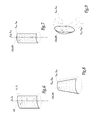
- FIGs 7, 8 and 9 are represented diagrams similar to that of the figure 6 , so as to illustrate variants for the articular surfaces 4 and 6 of the implant 1.
- metacarpal 104 and trapezial articular surfaces 106 which each correspond to an axial segment of a cylinder, centered on an axis X 104 , X 106 and whose cross section S 104 , S 106 is circular centered on the axis supra.
- the surfaces 4 and 6 and the surfaces 104 and 106 are distinguished only by the geometric shape of their cross section, namely elliptical for the surfaces 4 and 6 and circular for the surfaces 104 and 106.
- metacarpal 204 and trapezial joint surfaces 206 each corresponding to an axial segment of a cone, centered on an axis X 204 , X 206 and whose cross section S 204 , S 206 is circular.
- the aforementioned sections S 204 and S 206 may be elliptical.
- the cross section S 304 , S 306 of the aforementioned torus may be provided elliptical.
- the circular section or the elliptical section of this torus may increase or decrease along the axis.
- the curved geometry of the sections S 104 , S 106 , S 204 , S 206 , S 304 and S 306 can either be strictly circular or elliptical, or, conversely, have variations of curvature following its periphery.
- the circular or elliptical geometry of the sections S 104 , S 106 , S 204 , S 206 , S 304 and / or S 306 may have a greater curvature. small in the central region of the corresponding articular surfaces 104, 106, 204, 206, 304, 306 and / or have a greater curvature in the peripheral region of this articular surface, relative to the remainder of this cross section.
- FIGS. 6 to 9 thus illustrate the multiplicity of construction geometries of the metacarpal and trapezial articular surfaces of the implant 1: these various construction geometries all provide joint mobility close to the anatomical mobility of the trapezio-metacarpal joint once the body 2 is implanted.
- the two opposite articulating surfaces 4 and 6, 104 and 106, 204 and 206, and 304 and 306 of the implant 1 are arranged orthogonally to one another, i.e. so that their central axes X 4 and X 6 , X 104 and X 106 , X 204 and X 206 , and X 304 and X 306 extend substantially perpendicular to each other.
- the geometry of construction relative to the metacarpal articular surface can be the same, with a dimensioning that is strictly identical or different, or else be different from the geometry of construction chosen for the surface. trapezial joint.
Abstract
Description
La présente invention concerne un implant d'articulation trapézo-métacarpienne. Elle concerne également une méthode chirurgicale de pose d'un tel implant.The present invention relates to a trapezio-metacarpal joint implant. It also relates to a surgical method of laying such an implant.
Les prothèses et les implants trapézo-métacarpiens sont destinés à rétablir la force et la mobilité de l'articulation anatomique du pouce, entre son métacarpien et le trapèze lorsque cette articulation est endommagée par un processus pathologique dégénératif ou inflammatoire. L'invention s'intéresse ainsi plus particulièrement aux implants trapézo-métacarpiens destinés à traiter une arthrose peu destructrice et relativement centrée.Prostheses and trapezio-metacarpal implants are intended to restore the strength and mobility of the anatomical joint of the thumb, between its metacarpal and the trapezius when this joint is damaged by a degenerative or inflammatory pathological process. The invention is thus more particularly interested in trapezio-metacarpal implants intended to treat a non-destructive and relatively centered osteoarthritis.
Les prothèses trapézo-métacarpiennes connues sont des prothèses à tige, c'est-à-dire dont le composant prothétique métacarpien est, d'un côté, ancré dans le métacarpien par une tige allongée, tandis que, de l'autre côté, ce composant prothétique est monté rotulant soit dans un composant prothétique rapporté fixement au trapèze, soit dans une cavité creusée directement dans le trapèze. L'implantation de ces prothèses totales ou partielles nécessitent donc d'entamer considérablement la matière osseuse de l'articulation trapézo-métacarpienne et rétablit une mobilité de type rotule qui ne correspond pas, d'un point de vue cinématique, à la mobilité articulaire anatomique. De plus, en cas de mauvaise implantation, les risques d'usure, de luxation, voire de fracture de la prothèse sont réels.Known trapezio-metacarpal prostheses are prosthetic rods, that is to say whose prosthetic component metacarpal is, on one side, anchored in the metacarpal by an elongated rod, while on the other side, prosthetic component is rotatably mounted either in a prosthetic component fixedly attached to the trapezium, or in a cavity hollowed directly into the trapezium. Implantation of these total or partial prostheses therefore requires considerably lowering the bone material of the trapezio-metacarpal joint and restoring a mobility of the ball-and-socket type that does not correspond, kinematically, to anatomical articular mobility. . In addition, in case of poor implantation, the risk of wear, dislocation, or fracture of the prosthesis are real.
On connaît par ailleurs, par exemple de
Le but de la présente invention est de proposer un implant trapézo-métacarpien, dont l'implantation est pérenne et qui fournit une mobilité plus proche de la mobilité anatomique de l'articulation trapézo-métacarpienne.The aim of the present invention is to propose a trapezio-metacarpal implant, the implantation of which is perennial and which provides a mobility closer to the anatomical mobility of the trapezio-metacarpal joint.
A cet effet, l'invention a pour objet un implant d'articulation trapézo-métacarpienne, tel que défini à la revendication 1.For this purpose, the subject of the invention is a trapezio-metacarpal joint implant, as defined in
Est également présentée ici une méthode chirurgicale de pose d'un implant d'articulation trapézo-métacarpienne tel que défini ci-dessus, dans laquelle :
- on accède à la zone articulaire entre le métacarpien et le trapèze d'un patient,
- on prépare la surface osseuse corticale du trapèze de manière sensiblement complémentaire à la surface articulaire trapézienne définie par le corps de l'implant et, si besoin, on prépare la surface osseuse corticale du métacarpien de manière sensiblement complémentaire à la surface articulaire métacarpienne définie par le corps de l'implant, et
- on interpose le corps de l'implant entre le trapèze et le métacarpien de manière que l'axe associé à la surface articulaire trapézienne s'étend dans l'un des plans antéro-postérieur et frontal du patient, tandis que l'axe associé à la surface articulaire métacarpienne s'étend dans l'autre de ces plans.
- we reach the articular zone between the metacarpal and the trapezius of a patient,
- the cortical bone surface of the trapezium is prepared substantially complementary to the trapezial articular surface defined by the body of the implant and, if necessary, the cortical bone surface of the metacarpal is prepared substantially complementary to the metacarpal articular surface defined by the body of the implant, and
- the body of the implant is interposed between the trapezium and the metacarpal so that the axis associated with the trapezial articular surface extends in one of the anteroposterior and frontal planes of the patient, while the axis associated with the metacarpal articular surface extends into the other of these planes.
L'idée à la base de l'invention est d'interposer entre le trapèze et le métacarpien un corps non pas volumineux et sphérique ou ellipsoïdal, mais un corps relativement fin et avec des surfaces articulaires opposées, qui sont concaves au moins dans une direction et contre lesquelles vont s'appuyer pour rouler et glisser les surfaces osseuses corticales du trapèze et du métacarpien. Pour reproduire aussi fidèlement que possible le comportement anatomique de l'articulation trapézo-métacarpienne, de type selle de cheval, les deux surfaces articulaires sont réalisées par des segments axiaux de cylindre, de cône et/ou de tore, dont les axes centraux ou, plus généralement, pour tenir compte du fait que l'axe central d'un segment axial de tore est courbe, les projections de ces axes centraux sur le plan médian de l'implant sont sensiblement perpendiculaires l'une à l'autre : le corps de l'implant conforme à l'invention dissocie la selle de cheval anatomique en ces deux surfaces articulaires. D'un point de vue cinématique, ces deux surfaces articulaires orthogonales autorisent une mobilité pivotante autour des deux axes centraux précités, à la façon d'un joint de cardan auquel l'articulation trapézo-métacarpienne est assimilée d'un point de vue de mécanique théorique. De plus, la courbure de ces deux surfaces articulaires stabilise et aligne le corps de l'implant entre le trapèze et le métacarpien, ce qui évite de prévoir des moyens de fixation osseuse. En outre, l'invention présente l'avantage de maximiser l'étendue du contact entre l'implant et les os du trapèze et du métacarpien, au niveau de ces deux surfaces articulaires. Il en résulte que l'implant ne s'enfonce pas dans les os, préservant ainsi sa mobilité.The idea underlying the invention is to interpose between the trapezium and the metacarpal a non-voluminous body and spherical or ellipsoidal, but a relatively thin body and with opposite articular surfaces, which are concave at least in one direction and against which will lean to roll and slide the cortical bone surfaces of the trapezius and metacarpal. To reproduce as faithfully as possible the anatomical behavior of the trapezo-metacarpal knuckle, of the saddle type, the two articular surfaces are made by axial segments of cylinder, cone and / or torus, whose central axes or, more generally, to take account of the fact that the central axis of an axial torus segment is curved, the projections of these central axes on the median plane of the implant are substantially perpendicular to each other: the body of the implant according to the invention dissociates the saddle of anatomical horse in these two articular surfaces. From a cinematic point of view, these two orthogonal articular surfaces allow pivotal mobility around the two aforementioned central axes, in the manner of a universal joint to which the trapezio-metacarpal joint is assimilated from a theoretical mechanical point of view. In addition, the curvature of these two articular surfaces stabilizes and aligns the body of the implant between the trapezium and the metacarpal, which avoids the provision of bone fixation means. In addition, the invention has the advantage of maximizing the extent of contact between the implant and the bones of the trapezius and the metacarpal, at these two articular surfaces. As a result, the implant does not sink into the bones, thus preserving its mobility.
En pratique, le corps de l'implant selon l'invention présente une épaisseur la plus petite possible, étant entendu qu'une gamme de plusieurs épaisseurs peut être proposée selon le degré d'usure de l'articulation à traiter. Cette faible épaisseur vise à limiter au maximum les découpes osseuses nécessaires pour rendre complémentaire les surfaces osseuses corticales en regard du trapèze et du métacarpien avec les surfaces articulaires du corps de l'implant, par ajustement de la conformation de ces surfaces osseuses corticales, étant remarqué que, dans leur état anatomique non altéré, les surfaces osseuses corticales du trapèze et du métacarpien sont proches de conformations optimales pour coopérer avec le corps de l'implant. D'ailleurs, pour certaines articulations trapézo-métacarpiennes peu altérées, la recoupe sur le métacarpien peut être minime, voire nulle. Dans tous les cas, la taille de l'implant doit permettre de stabiliser immédiatement son corps par la seule contrainte de l'enveloppe capsulaire et ligamentaire autour de l'articulation entre le trapèze et le métacarpien, sans pour autant que ce corps subisse une hyper-contrainte puisqu'il doit conserver une certaine liberté afin que sa position s'adapte en fonction des contraintes de l'enveloppe articulaire, liées aux différents mouvements possibles de cette articulation.In practice, the body of the implant according to the invention has the smallest possible thickness, it being understood that a range of several thicknesses can be proposed according to the degree of wear of the joint to be treated. This small thickness aims to limit as much as possible the bone cuts necessary to complement the cortical bone surfaces facing the trapezius and the metacarpal with the articular surfaces of the body of the implant, by adjusting the conformation of these cortical bone surfaces, being noticed. that, in their unaltered anatomical state, the cortical bone surfaces of the trapezius and metacarpal are close to optimal conformations to cooperate with the body of the implant. Moreover, for some slightly altered Trapezo-metacarpal joints, the cut on the metacarpal may be minimal or even nil. In all cases, the size of the implant must allow to stabilize immediately his body by the sole constraint of the capsular and ligamentous envelope around the joint between the trapezius and the metacarpal, without this body undergoes hyper -constraint since it must maintain a certain freedom so that its position adapts according to the constraints of the articular envelope, related to the different possible movements of this articulation.
D'autres caractéristiques avantageuses de l'implant conforme à l'invention, prises isolément ou selon toutes les combinaisons techniquement possibles, sont spécifiées aux revendications dépendantes 2 à 10.Other advantageous features of the implant according to the invention, taken individually or in any technically possible combination, are specified in the
L'invention sera mieux comprise à la lecture de la description qui va suivre, donnée uniquement à titre d'exemple et faite en se référant aux dessins sur lesquels :
- la
figure 1 est une vue en élévation représentant certains des constituants osseux d'une main humaine gauche, dans laquelle est implanté un implant conforme à l'invention ; - la
figure 2 est une vue en perspective de l'implant de lafigure 1 ; - la
figure 3 est une vue en élévation selon la flèche III de lafigure 2 ; - les
figures 4 et5 sont des coupes selon respectivement les lignes IV-IV et V-V de lafigure 3 , montrant également en partie les os de la main après mise en place de l'implant ; - la
figure 6 est un schéma illustrant la géométrie de construction des surfaces articulaires de l'implant desfigures 1 à 5 ; et - les
figures 7 à 9 sont des vues analogues à lafigure 6 , illustrant respectivement des variantes pour la géométrie de construction des surfaces articulaires de l'implant conforme à l'invention.
- the
figure 1 is an elevational view showing some of the bone components of a left human hand, in which is implanted an implant according to the invention; - the
figure 2 is a perspective view of the implant of thefigure 1 ; - the
figure 3 is an elevation view along arrow III of thefigure 2 ; - the
figures 4 and5 are sections along lines IV-IV and VV respectively of thefigure 3 , also showing in part the bones of the hand after placement of the implant; - the
figure 6 is a diagram illustrating the construction geometry of the articular surfaces of the implant ofFigures 1 to 5 ; and - the
Figures 7 to 9 are similar views to thefigure 6 , respectively illustrating variants for the construction geometry of the articular surfaces of the implant according to the invention.
Sur les
L'implant 1 comporte un corps 2 globalement discoïdal, centré sur un axe géométrique référencé Z-Z. Le corps 2 délimite ainsi, d'une part, deux surfaces principales 4 et 6 opposées selon l'axe Z-Z, qui sont séparées l'une de l'autre par l'épaisseur, selon cet axe Z-Z, du corps 2, et, d'autre part, une surface périphérique 8, qui relie l'une à l'autre les surfaces 4 et 6 et dont les génératrices, dans l'exemple de réalisation considéré ici, sont parallèles à l'axe Z-Z. En coupe transversale à l'axe Z-Z, le corps 2 présente un contour extérieur rectangulaire aux coins émoussés. En variantes non représentées, d'autres formes sont envisageables pour ce contour, telles qu'un carré, un rond, une ellipse, etc.The
Dans la forme de réalisation envisagée sur les figures, l'implant 1 n'est constitué que du corps 2, dans le sens où l'implant ne comporte aucun autre composant, notamment aucun composant de fixation osseuse qui permettrait d'ancrer fixement le corps 2 dans le métacarpien M ou dans le trapèze T. Dans ce cas, le corps 2 constitue un implant exclusivement d'interposition de manière que ce corps présente, après implantation entre le métacarpien et le trapèze, une certaine liberté de mouvement, sa position s'adaptant aux contraintes qui lui sont appliquées, en fonction des mouvements de l'articulation trapézo-métacarpienne.In the embodiment envisaged in the figures, the
Dans cette optique, le corps 2 est avantageusement réalisé d'un seul tenant en un bloc de graphite recouvert de carbone pyrolytique, ce qui confère à ce corps une bonne biocompatibilité, une haute résistance mécanique et une bonne tenue à l'usure vis-à-vis des os métacarpien et trapèze. En pratique, d'autres matériaux peuvent être utilisés, notamment un alliage métallique à base de chrome et de cobalt, une matière plastique, comme le polyéthylène et le PEEK, du silicone, de la céramique, etc.In this view, the
La surface 4 est concave. Elle correspond géométriquement à une portion de cylindre, qui est centrée sur un axe X4 et dont la section transversale S4, qui est constante suivant l'axe X4 et qui correspond donc à la directrice de la surface 4, est sensiblement elliptique, comme bien visible sur la
De même, la surface 6 est concave et correspond à une portion de cylindre, dont la section transversale S6 est sensiblement elliptique et qui est centrée sur un axe X6 perpendiculaire, ici de manière séquente, avec l'axe Z-Z, comme bien visible sur la
Ainsi, les axes X4 et X6 s'étendent de manière perpendiculaire l'un à l'autre, de manière non séquente. En particulier, les lignes de fond 41 et 61, qui appartiennent respectivement aux surfaces 4 et 6 et qui s'étendent respectivement parallèlement aux axes X4 et X6, s'étendent de manière perpendiculaire l'une à l'autre, en étant séparées, selon l'axe Z-Z, par la partie centrale 21 du corps 2. Autrement dit, dans un plan médian π du corps 2, qui est perpendiculaire à l'axe Z-Z et de part et d'autre duquel sont situées les surfaces 4 et 6, les projections respectives de ces axes X4 et X6 sont perpendiculaires et sécantes.Thus, the X 4 and X 6 axes extend perpendicularly to one another, non-sequentially. In particular, the
De par les caractéristiques géométriques des surfaces 4 et 6, on comprend que, en coupe transversale passant par l'axe Z-Z, le corps 2 présente une épaisseur variable, en étant minimale dans la partie centrale 21 du corps tandis qu'elle est progressivement croissante en s'éloignant de cette partie centrale 21, jusque dans la partie périphérique 22 du corps 2, comme bien visible sur les
D'autres caractéristiques de l'implant 1 apparaitront ci-après, dans le cadre de la description d'un exemple de mise en place de cet implant entre le métacarpien M et le trapèze T montrés à la
Dans un premier temps opératoire, un chirurgien accède à la zone articulaire entre le métacarpien M et le trapèze T, via une voie d'abord postérieure ou antéro-latérale. Pour accéder à l'espace inter-osseux entre le métacarpien et le trapèze, la capsule articulaire et les ligaments entourant cette zone articulaire sont soit respectés, en étant écartés, soit partiellement incisés, étant entendu que cette capsule et ses ligaments seront alors reconstruits en fin d'intervention.In the first stage, a surgeon accesses the articular area between the metacarpal M and the trapezium T via a posterior or anterolateral approach. To access the interosseous space between the metacarpal and the trapezium, the articular capsule and the ligaments surrounding this articular area are either respected, being separated, or partially incised, it being understood that this capsule and its ligaments will then be reconstructed. end of intervention.
Dans un deuxième temps opératoire, le chirurgien écarte l'un de l'autre le métacarpien M et le trapèze T afin d'élargir l'espace inter-osseux, notamment en exerçant un effort de traction suivant la direction longitudinale du métacarpien. Le chirurgien peut alors préparer les surfaces osseuses en regard délimitées par le métacarpien M et le trapèze T, de manière à les conformer de façon complémentaire aux surfaces 4 et 6 du corps 2 de l'implant 1.In a second operative step, the surgeon separates the metacarpal M and the trapezium T from one another to widen the interosseous space, in particular by exerting a tensile force along the longitudinal direction of the metacarpal. The surgeon can then prepare the facing bone surfaces delimited by the metacarpal M and the trapezium T, so as to complement them to the
En pratique, on notera que les extrémités en regard du métacarpien M et du trapèze T présentent des géométries de surface respectives proches de surfaces complémentaires aux surfaces 4 et 6. En effet, ces extrémités osseuses présentent, dans leur état anatomique, des formes en selle de cheval, qui s'emboîtent orthogonalement l'une dans l'autre. Ainsi, les découpes osseuses réalisées sur les extrémités en regard du métacarpien et du trapèze sont minimes pour adapter la surface de ces os aux surfaces 4 et 6 du corps 2. D'ailleurs, en pratique, ces découpes sont minimes voire inutiles sur le métacarpien, tandis que, en général, des découpes plus importantes doivent être réalisées sur le trapèze. Ainsi, la préparation des extrémités du métacarpien M et du trapèze T n'entame pas profondément ces os, en restant au niveau de leur couche corticale osseuse.In practice, it will be noted that the opposite ends of the metacarpal M and the trapezium T have respective surface geometries close to complementary surfaces to the
Dans un troisième temps opératoire, tout en maintenant la traction sur l'articulation trapézo-métacarpienne selon la direction longitudinale du métacarpien M, le chirurgien positionne l'implant 1 dans l'espace inter-osseux séparant le métacarpien et le trapèze T, en interposant le corps 2 entre ces deux os de manière que la surface 4 est tournée vers le métacarpien, avec l'axe X4 s'étendant dans un plan frontal, tandis que la surface 6 est tournée vers le trapèze, avec l'axe X6 qui s'étend dans un plan antéro-postérieur, étant entendu que les termes « frontal », « antéro-postérieur » et similaires s'entendent ici dans leur sens anatomique, par rapport au patient dont la main est opérée. En variante non représentée, l'implant 1 est mis en place, entre le métacarpien M et la trapèze T, dans une configuration basculée de 90° autour de l'axe Z-Z : une préparation préalable des extrémités du métacarpien et du trapèze peut être nécessaire, mais cette variante illustre la capacité du corps 2 à être implanté de façon que ses surfaces articulaires 4 et 6 s'adaptent au mieux aux extrémités du métacarpien et du trapèze du patient opéré, selon l'état initial de ces extrémités osseuses et/ou pour minimiser la profondeur d'entame de ces extrémités lors de leur préparation.In a third operative step, while maintaining the traction on the trapezio-metacarpal joint in the longitudinal direction of the metacarpal M, the surgeon positions the
Une fois que l'implant 1 est ainsi positionné entre le métacarpien M et le trapèze T, la traction axiale précitée est relâchée, de sorte que la capsule articulaire et les ligaments entourant l'articulation trapézo-métacarpienne rapprochent l'un de l'autre le métacarpien et le trapèze. Le corps 2 de l'implant 1 se trouve alors retenu de manière mobile entre le métacarpien et le trapèze, sous la contrainte de la capsule et des ligaments, autrement dit sous une contrainte dont la résultante est sensiblement alignée avec l'axe Z-Z. Le chirurgien peut ensuite refermer les tissus mous autour de l'articulation, le cas échéant par reconstruction, voire moyennant une ligamentoplastie.Once the
L'articulation trapézo-métacarpienne ainsi munie de l'implant 1 retrouve un comportement cinématique proche, voire quasi-identique aux comportements anatomiques d'origine de cette articulation. En effet, le métacarpien M s'articule alors contre la surface 4, essentiellement par basculement autour de l'axe X4, tandis que, dans le même temps, le trapèze T s'articule contre la surface 6, essentiellement par basculement autour de l'axe X6. Grâce à l'implant 1, le métacarpien M et le trapèze T sont articulés l'un par rapport à l'autre à la façon d'un joint de cardan, autour des deux axes perpendiculaires X4 et X6. Cette cinématique de joint de cardan reproduit efficacement l'articulation anatomique sellaire entre le métacarpien et le trapèze. De plus, on notera que les surfaces 4 et 6 s'appuient alors contre les couches corticales osseuses respectives du métacarpien M et du trapèze T, ce qui évite que le corps 2 ne s'enfonce dans l'un et/ou l'autre de ces os. La mobilité fournie par l'implant 1 est ainsi pérenne.The trapezio-metacarpal joint thus provided with the
Avantageusement, pour favoriser les mouvements de roulement et de glissement du métacarpien M et du trapèze T contre respectivement les parties centrales 42 respectives des surfaces 4 et 6, la section elliptique S4, S6 de ces surfaces présente, dans ces régions centrales 42, 62, une courbure plus petite que le reste de la section. Autrement dit, les régions centrales 42 et 62 des surfaces 4 et 6 sont alors un peu plus aplaties, c'est-à-dire un peu moins courbées que le reste de ces surfaces.Advantageously, to promote the rolling and sliding movements of the metacarpal M and trapezium T respectively against the parts
Par ailleurs, en service, le corps 2 est stabilisé entre le métacarpien M et le trapèze T du fait de la courbure elliptique des sections respectives S4, S6 des surfaces 4 et 6. Avantageusement, pour renforcer cette stabilité, la section des régions périphériques respectives 43 et 63 des surfaces 4 et 6 présente une courbure plus grande que le reste de cette section : en exagérant ainsi la courbure des surfaces 4 et 6 au niveau de leur bordure d'extrémité périphérique, la coopération surfacique du corps 2 et des os du métacarpien M et du trapèze T auto-stabilise l'implant 1. De surcroît, les régions périphériques 43 et 63 des surfaces 4 et 6 peuvent ainsi compenser l'usure périphérique, liée à l'arthrose, des extrémités osseuses en regard du métacarpien et du trapèze.Moreover, in use, the
En pratique, on comprend que, dans la mesure où le corps 2 est un implant d'interposition, son épaisseur suivant l'axe Z-Z est limitée, dans le sens où la présence de ce corps ne doit pas entraîner une hypercontrainte de l'articulation trapézo-métacarpienne. Ainsi, à titre d'exemple numérique, l'épaisseur maximale e2 du corps 2, c'est-à-dire son épaisseur entre les régions périphériques 43 et 63 des surfaces 4 et 6, est prévue inférieure à 5 mm, en particulier jusqu'à être égale à 1 mm environ.In practice, it is understood that, insofar as the
De même, pour s'adapter au mieux à l'espace inter-osseux entre le métacarpien M et le trapèze T, la surface 6 présente avantageusement une dimension L6, suivant son axe X6, supérieure à la dimension L4, suivant l'axe X4, de la surface 4.Similarly, to best adapt to the interosseous space between the metacarpal M and the trapezium T, the
Par ailleurs, la géométrie des surfaces articulaires métacarpien et trapèze peut être construite de manière différente de celle des surfaces 4 et 6 décrites jusqu'ici. Pour bien comprendre cet aspect de l'invention, on a représenté, sur la
Sur les
De même, sur la
Egalement de même, sur la
A titre de variantes non représentées, la section transversale S304, S306 du tore précité peut être prévue elliptique. De même, également à titre de variante non représentée, plutôt que d'être constante suivant l'axe X304, X306, la section circulaire ou la section elliptique de ce tore peut augmenter ou diminuer suivant l'axe.As variations not shown, the cross section S 304 , S 306 of the aforementioned torus may be provided elliptical. Similarly, also as a variant not shown, rather than being constant along the axis X 304 , X 306 , the circular section or the elliptical section of this torus may increase or decrease along the axis.
En outre, également à titre de variantes, la géométrie incurvée des sections S104, S106, S204, S206, S304 et S306 peut soit être rigoureusement circulaire ou elliptique, soit, au contraire, présenter des variations de courbure suivant sa périphérie. En particulier, comme évoqué plus haut pour la géométrie elliptique des sections S4 et S6, la géométrie circulaire ou elliptique des sections S104, S106, S204, S206, S304 et/ou S306 peut présenter une courbure plus petite dans la région centrale des surfaces articulaires correspondantes 104, 106, 204, 206, 304, 306 et/ou présenter une courbure plus grande dans la région périphérique de cette surface articulaire, par rapport au reste de cette section transversale.In addition, also as variants, the curved geometry of the sections S 104 , S 106 , S 204 , S 206 , S 304 and S 306 can either be strictly circular or elliptical, or, conversely, have variations of curvature following its periphery. In particular, as mentioned above for the elliptical geometry of the sections S 4 and S 6 , the circular or elliptical geometry of the sections S 104 , S 106 , S 204 , S 206 , S 304 and / or S 306 may have a greater curvature. small in the central region of the corresponding
Les
On comprend également que la géométrie de construction relative à la surface articulaire métacarpienne, choisie parmi toutes celles évoquées ci-dessus, peut être la même, avec un dimensionnement rigoureusement identique ou différent, ou bien être différente de la géométrie de construction choisie pour la surface articulaire trapézienne.It is also understood that the geometry of construction relative to the metacarpal articular surface, chosen from all those mentioned above, can be the same, with a dimensioning that is strictly identical or different, or else be different from the geometry of construction chosen for the surface. trapezial joint.
Claims (10)
comportant un corps (2) définissant une surface articulaire métacarpienne (4 ; 104 ; 204 ; 304) et une surface articulaire trapézienne (6 ; 106 ; 206 ; 306), qui sont situées, au moins pour leur région centrale (42, 62), de part et d'autre d'un plan médian (π) du corps, caractérisé en ce que les surfaces articulaires métacarpienne (4 ; 104 ; 204 ; 304) et trapézienne (6 ; 106 ; 206 ; 306) correspondent chacune à un segment axial de cylindre, de cône ou de tore, ces deux segments axiaux de cylindre, de cône et/ou de tore étant centrés sur des axes respectifs (X4, X6 ; X104, X106 ; X204, X206 ; X304, X306) qui, projetés sur le plan médian, sont sensiblement perpendiculaires l'un à l'autre.Trapezo-metacarpal joint implant,
having a body (2) defining a metacarpal articular surface (4; 104; 204; 304) and a trapezial articular surface (6; 106; 206; 306) which are located at least for their central region (42,62) on either side of a median plane (π) of the body, characterized in that the metacarpal (4; 104; 204; 304) and trapezial (6; 106; 206; 306) articular surfaces each correspond to a axial segment of cylinder, cone or torus, these two axial segments of cylinder, cone and / or torus being centered on respective axes (X 4 , X 6 , X 104 , X 106 , X 204 , X 206 ; X 304 , X 306 ) which, projected on the median plane, are substantially perpendicular to each other.
Applications Claiming Priority (1)
| Application Number | Priority Date | Filing Date | Title |
|---|---|---|---|
| FR0954190A FR2946864B1 (en) | 2009-06-19 | 2009-06-19 | TRAPEZO-METACARPIAN JOINT IMPLANT |
Publications (2)
| Publication Number | Publication Date |
|---|---|
| EP2263614A1 true EP2263614A1 (en) | 2010-12-22 |
| EP2263614B1 EP2263614B1 (en) | 2012-12-19 |
Family
ID=41682741
Family Applications (1)
| Application Number | Title | Priority Date | Filing Date |
|---|---|---|---|
| EP10166447A Active EP2263614B1 (en) | 2009-06-19 | 2010-06-18 | Trapezo-metacarpal joint implant |
Country Status (3)
| Country | Link |
|---|---|
| US (2) | US9408706B2 (en) |
| EP (1) | EP2263614B1 (en) |
| FR (1) | FR2946864B1 (en) |
Cited By (2)
| Publication number | Priority date | Publication date | Assignee | Title |
|---|---|---|---|---|
| EP2687189A1 (en) | 2009-06-19 | 2014-01-22 | Tornier | Interpositional trapezium implant |
| US9408706B2 (en) | 2009-06-19 | 2016-08-09 | Tornier | Trapeziometacarpal joint implant and associated methods |
Families Citing this family (10)
| Publication number | Priority date | Publication date | Assignee | Title |
|---|---|---|---|---|
| AU2011314157A1 (en) | 2010-09-29 | 2013-05-09 | Zimmer, Inc. | Pyrolytic carbon implants with porous fixation component and methods of making the same |
| EP2757964B1 (en) | 2011-05-26 | 2016-05-04 | Cartiva, Inc. | Tapered joint implant and related tools |
| US8734491B2 (en) | 2011-08-24 | 2014-05-27 | Instratek, Inc. | Method and apparatus for the stabilization of the trapeziometacarpal joint |
| US9681960B2 (en) | 2014-05-16 | 2017-06-20 | Howmedica Osteonics Corp. | Guides for fracture system |
| US10575968B2 (en) | 2014-05-16 | 2020-03-03 | Howmedica Osteonics Corp. | Guides for fracture system |
| AU2016243660B2 (en) | 2015-03-31 | 2020-11-12 | Cartiva, Inc. | Carpometacarpal (CMC) implants and methods |
| WO2016161025A1 (en) | 2015-03-31 | 2016-10-06 | Cartiva, Inc. | Hydrogel implants with porous materials and methods |
| AU2016248062B2 (en) | 2015-04-14 | 2020-01-23 | Cartiva, Inc. | Tooling for creating tapered opening in tissue and related methods |
| US11035381B2 (en) | 2015-09-16 | 2021-06-15 | Regal Beloit America, Inc. | Blower, electric machine and associated method |
| US11642226B2 (en) | 2020-05-01 | 2023-05-09 | Ensemble Orthopedics, Inc. | Implantable interpositional orthopedic pain management |
Citations (4)
| Publication number | Priority date | Publication date | Assignee | Title |
|---|---|---|---|---|
| WO1997042895A1 (en) * | 1996-05-13 | 1997-11-20 | Wright Medical Technology, Inc. | Instrumentation for implanting a spherical prosthesis |
| US6436146B1 (en) | 1997-12-10 | 2002-08-20 | Bioprofile | Implant for treating ailments of a joint or a bone |
| WO2004093767A1 (en) * | 2003-04-18 | 2004-11-04 | Ascension Orthopedics, Inc. | Interpositional biarticular disk implant |
| US20060241758A1 (en) * | 2005-04-20 | 2006-10-26 | Sdgi Holdings, Inc. | Facet spacers |
Family Cites Families (25)
| Publication number | Priority date | Publication date | Assignee | Title |
|---|---|---|---|---|
| FR2465470A1 (en) | 1979-08-07 | 1981-03-27 | Gauthier Georges | Articulated joint surgical prosthesis - has twin spherical surfaces in each mating part with prolongations for lateral movement |
| EP0176728B1 (en) * | 1984-09-04 | 1989-07-26 | Humboldt-Universität zu Berlin | Intervertebral-disc prosthesis |
| US4936860A (en) * | 1988-09-23 | 1990-06-26 | Swanson Alfred B | Metal scaphoid implant |
| WO1993000053A1 (en) * | 1991-06-25 | 1993-01-07 | Orthopaedic Biosystems Limited | Non-constrained total joint system |
| US5326364A (en) * | 1992-12-16 | 1994-07-05 | Wright Medical Technology, Inc. | Trapezial implant |
| US5425777A (en) * | 1992-12-23 | 1995-06-20 | Sarkisian; James S. | Artificial finger joint |
| US5702472A (en) * | 1996-12-26 | 1997-12-30 | Huebner; Randall J. | Phalangeal finger joint prosthesis and method |
| FR2709948B1 (en) | 1993-09-16 | 1995-11-17 | Dominique Saragaglia | Metatarsophalangeal total prosthesis for cementless resurfacing. |
| US5522900A (en) * | 1993-12-17 | 1996-06-04 | Avanta Orthopaedics | Prosthetic joint and method of manufacture |
| US5683466A (en) * | 1996-03-26 | 1997-11-04 | Vitale; Glenn C. | Joint surface replacement system |
| US6017366A (en) * | 1997-04-18 | 2000-01-25 | W. L. Gore & Associates, Inc. | Resorbable interposition arthroplasty implant |
| DE10130796A1 (en) | 2001-06-26 | 2003-01-23 | Ulrich Muender | Implantable replacement finger joint prosthesis system of modular structure, with proximal and distal implant elements, has a configuration and a mode of functioning making it adaptable for different applications |
| FR2833156B1 (en) * | 2001-12-12 | 2004-10-15 | Bioprofile | TRAPEZIAN OR TRAPEZO-METACARPIAN IMPLANT |
| FR2858545B1 (en) | 2003-08-06 | 2005-11-04 | Depuy France | METATARSO-PHALANGIAN TOTAL PROSTHESIS, AND ANCILLARIES FOR THE ESTABLISHMENT OF THIS PROSTHESIS. |
| US7691146B2 (en) * | 2003-11-21 | 2010-04-06 | Kyphon Sarl | Method of laterally inserting an artificial vertebral disk replacement implant with curved spacer |
| EP1758524A1 (en) | 2004-06-23 | 2007-03-07 | De Villiers, Malan | Digital joint arthroplasty |
| FR2875398B1 (en) | 2004-09-21 | 2007-07-06 | Newdeal Sa Sa | JOINT IMPLANT OF INTERPOSITION |
| US20080051912A1 (en) * | 2004-11-08 | 2008-02-28 | Small Bone Innovations, Inc. | Metatarsal implant |
| US20060241777A1 (en) | 2004-11-30 | 2006-10-26 | Partin Jason I | Resorbable medical implants and methods |
| US9119613B2 (en) | 2008-01-07 | 2015-09-01 | Extremity Medical Llc | System and method for trapezium bone replacement |
| US8012217B2 (en) * | 2008-07-03 | 2011-09-06 | Fellowship of Orthopaedic Researchers, LLC | Talar implants and methods of use |
| US20100057216A1 (en) | 2008-07-23 | 2010-03-04 | Jamy Gannoe | System and method for joint resurfacing with dynamic fixation |
| US20100249942A1 (en) * | 2009-03-27 | 2010-09-30 | Wright State University | Toe joint replacement models |
| FR2946864B1 (en) | 2009-06-19 | 2011-07-08 | Tornier Sa | TRAPEZO-METACARPIAN JOINT IMPLANT |
| FR2957780B3 (en) | 2010-03-29 | 2012-04-06 | Xavier Renard | PROTHETIC IMPLANT INTENDED TO BE PLACED BETWEEN TWO SMALL BONE DIMENSIONS |
-
2009
- 2009-06-19 FR FR0954190A patent/FR2946864B1/en not_active Expired - Fee Related
-
2010
- 2010-06-18 EP EP10166447A patent/EP2263614B1/en active Active
- 2010-06-21 US US12/819,390 patent/US9408706B2/en active Active
-
2016
- 2016-05-27 US US15/166,941 patent/US9788959B2/en active Active
Patent Citations (4)
| Publication number | Priority date | Publication date | Assignee | Title |
|---|---|---|---|---|
| WO1997042895A1 (en) * | 1996-05-13 | 1997-11-20 | Wright Medical Technology, Inc. | Instrumentation for implanting a spherical prosthesis |
| US6436146B1 (en) | 1997-12-10 | 2002-08-20 | Bioprofile | Implant for treating ailments of a joint or a bone |
| WO2004093767A1 (en) * | 2003-04-18 | 2004-11-04 | Ascension Orthopedics, Inc. | Interpositional biarticular disk implant |
| US20060241758A1 (en) * | 2005-04-20 | 2006-10-26 | Sdgi Holdings, Inc. | Facet spacers |
Cited By (6)
| Publication number | Priority date | Publication date | Assignee | Title |
|---|---|---|---|---|
| EP2687189A1 (en) | 2009-06-19 | 2014-01-22 | Tornier | Interpositional trapezium implant |
| US9408706B2 (en) | 2009-06-19 | 2016-08-09 | Tornier | Trapeziometacarpal joint implant and associated methods |
| US9572673B2 (en) | 2009-06-19 | 2017-02-21 | Tornier | Interposition implants for the hand |
| US9788959B2 (en) | 2009-06-19 | 2017-10-17 | Tornier | Trapeziometacarpal joint implant and associated methods |
| US10420650B2 (en) | 2009-06-19 | 2019-09-24 | Tornier | Interposition implants for the hand |
| US11141284B2 (en) | 2009-06-19 | 2021-10-12 | Tornier | Interposition implants for the hand |
Also Published As
| Publication number | Publication date |
|---|---|
| US20100324694A1 (en) | 2010-12-23 |
| FR2946864A1 (en) | 2010-12-24 |
| EP2263614B1 (en) | 2012-12-19 |
| US9408706B2 (en) | 2016-08-09 |
| US20160346093A1 (en) | 2016-12-01 |
| US9788959B2 (en) | 2017-10-17 |
| FR2946864B1 (en) | 2011-07-08 |
Similar Documents
| Publication | Publication Date | Title |
|---|---|---|
| EP2263614B1 (en) | Trapezo-metacarpal joint implant | |
| EP1637095B1 (en) | Interposition joint implant | |
| EP1948092B1 (en) | Implant, especially partial implant of the head of the ulna | |
| EP0127503B1 (en) | Shoulder prosthesis | |
| CA2466661C (en) | Posterior vertebral joint prosthesis | |
| EP0532440B1 (en) | Total wrist prosthesis | |
| EP1952771B1 (en) | Surgical instrument assembly for inserting a shoulder prosthesis | |
| EP2385812B1 (en) | Intramedullary anchoring stem for an orthopaedic implant head | |
| FR2912051A1 (en) | TRAPEZO-METACARPIAN IMPLANT | |
| CA2354165A1 (en) | Intervertebral disc prosthesis with contact blocks | |
| EP1263352A1 (en) | Disc prosthesis for cervical vertebra | |
| EP2091471A2 (en) | Prosthesis for nucleus or inter-vertebral disc replacement | |
| FR2805457A1 (en) | INTERVERTEBRAL IMPLANT A BODY AND FACE SUPPORT | |
| FR2605878A1 (en) | Prosthesis for small joints, in particular metacarpophalangial and interphalangial joints | |
| EP0845964B1 (en) | Joint prosthesis members and method for making same | |
| WO2005053579A1 (en) | Postero-lateral intervertebral disc prosthesis | |
| EP1112753B1 (en) | Mobile implant for interposition between two osseous surfaces | |
| EP0611560B1 (en) | Prosthetic element for small joints | |
| WO2009150320A1 (en) | Trapezio-metacarpal joint prosthesis | |
| EP2468217B1 (en) | Metatarsal hemiarthroplasty implant | |
| FR2673100A1 (en) | Wrist joint prosthesis | |
| EP2687189B1 (en) | Interpositional trapezium implant | |
| EP1214918A1 (en) | Intervertebral implant | |
| EP0794746B1 (en) | Joint implant and ancillary therefor | |
| FR2763835A1 (en) | Carpometacarpal implant |
Legal Events
| Date | Code | Title | Description |
|---|---|---|---|
| PUAI | Public reference made under article 153(3) epc to a published international application that has entered the european phase |
Free format text: ORIGINAL CODE: 0009012 |
|
| AK | Designated contracting states |
Kind code of ref document: A1 Designated state(s): AL AT BE BG CH CY CZ DE DK EE ES FI FR GB GR HR HU IE IS IT LI LT LU LV MC MK MT NL NO PL PT RO SE SI SK SM TR |
|
| AX | Request for extension of the european patent |
Extension state: BA ME RS |
|
| 17P | Request for examination filed |
Effective date: 20110509 |
|
| GRAP | Despatch of communication of intention to grant a patent |
Free format text: ORIGINAL CODE: EPIDOSNIGR1 |
|
| GRAS | Grant fee paid |
Free format text: ORIGINAL CODE: EPIDOSNIGR3 |
|
| GRAA | (expected) grant |
Free format text: ORIGINAL CODE: 0009210 |
|
| AK | Designated contracting states |
Kind code of ref document: B1 Designated state(s): AL AT BE BG CH CY CZ DE DK EE ES FI FR GB GR HR HU IE IS IT LI LT LU LV MC MK MT NL NO PL PT RO SE SI SK SM TR |
|
| RAP1 | Party data changed (applicant data changed or rights of an application transferred) |
Owner name: TORNIER |
|
| REG | Reference to a national code |
Ref country code: GB Ref legal event code: FG4D Free format text: NOT ENGLISH |
|
| REG | Reference to a national code |
Ref country code: CH Ref legal event code: EP |
|
| REG | Reference to a national code |
Ref country code: AT Ref legal event code: REF Ref document number: 588963 Country of ref document: AT Kind code of ref document: T Effective date: 20130115 |
|
| REG | Reference to a national code |
Ref country code: DE Ref legal event code: R096 Ref document number: 602010004160 Country of ref document: DE Effective date: 20130221 |
|
| PG25 | Lapsed in a contracting state [announced via postgrant information from national office to epo] |
Ref country code: ES Free format text: LAPSE BECAUSE OF FAILURE TO SUBMIT A TRANSLATION OF THE DESCRIPTION OR TO PAY THE FEE WITHIN THE PRESCRIBED TIME-LIMIT Effective date: 20130330 Ref country code: FI Free format text: LAPSE BECAUSE OF FAILURE TO SUBMIT A TRANSLATION OF THE DESCRIPTION OR TO PAY THE FEE WITHIN THE PRESCRIBED TIME-LIMIT Effective date: 20121219 Ref country code: LT Free format text: LAPSE BECAUSE OF FAILURE TO SUBMIT A TRANSLATION OF THE DESCRIPTION OR TO PAY THE FEE WITHIN THE PRESCRIBED TIME-LIMIT Effective date: 20121219 Ref country code: NO Free format text: LAPSE BECAUSE OF FAILURE TO SUBMIT A TRANSLATION OF THE DESCRIPTION OR TO PAY THE FEE WITHIN THE PRESCRIBED TIME-LIMIT Effective date: 20130319 Ref country code: HR Free format text: LAPSE BECAUSE OF FAILURE TO SUBMIT A TRANSLATION OF THE DESCRIPTION OR TO PAY THE FEE WITHIN THE PRESCRIBED TIME-LIMIT Effective date: 20121219 Ref country code: SE Free format text: LAPSE BECAUSE OF FAILURE TO SUBMIT A TRANSLATION OF THE DESCRIPTION OR TO PAY THE FEE WITHIN THE PRESCRIBED TIME-LIMIT Effective date: 20121219 |
|
| REG | Reference to a national code |
Ref country code: NL Ref legal event code: VDEP Effective date: 20121219 Ref country code: AT Ref legal event code: MK05 Ref document number: 588963 Country of ref document: AT Kind code of ref document: T Effective date: 20121219 |
|
| REG | Reference to a national code |
Ref country code: LT Ref legal event code: MG4D |
|
| PG25 | Lapsed in a contracting state [announced via postgrant information from national office to epo] |
Ref country code: LV Free format text: LAPSE BECAUSE OF FAILURE TO SUBMIT A TRANSLATION OF THE DESCRIPTION OR TO PAY THE FEE WITHIN THE PRESCRIBED TIME-LIMIT Effective date: 20121219 Ref country code: SI Free format text: LAPSE BECAUSE OF FAILURE TO SUBMIT A TRANSLATION OF THE DESCRIPTION OR TO PAY THE FEE WITHIN THE PRESCRIBED TIME-LIMIT Effective date: 20121219 Ref country code: GR Free format text: LAPSE BECAUSE OF FAILURE TO SUBMIT A TRANSLATION OF THE DESCRIPTION OR TO PAY THE FEE WITHIN THE PRESCRIBED TIME-LIMIT Effective date: 20130320 |
|
| REG | Reference to a national code |
Ref country code: FR Ref legal event code: GC Effective date: 20130515 |
|
| PG25 | Lapsed in a contracting state [announced via postgrant information from national office to epo] |
Ref country code: AT Free format text: LAPSE BECAUSE OF FAILURE TO SUBMIT A TRANSLATION OF THE DESCRIPTION OR TO PAY THE FEE WITHIN THE PRESCRIBED TIME-LIMIT Effective date: 20121219 Ref country code: IS Free format text: LAPSE BECAUSE OF FAILURE TO SUBMIT A TRANSLATION OF THE DESCRIPTION OR TO PAY THE FEE WITHIN THE PRESCRIBED TIME-LIMIT Effective date: 20130419 Ref country code: CZ Free format text: LAPSE BECAUSE OF FAILURE TO SUBMIT A TRANSLATION OF THE DESCRIPTION OR TO PAY THE FEE WITHIN THE PRESCRIBED TIME-LIMIT Effective date: 20121219 Ref country code: BG Free format text: LAPSE BECAUSE OF FAILURE TO SUBMIT A TRANSLATION OF THE DESCRIPTION OR TO PAY THE FEE WITHIN THE PRESCRIBED TIME-LIMIT Effective date: 20130319 Ref country code: EE Free format text: LAPSE BECAUSE OF FAILURE TO SUBMIT A TRANSLATION OF THE DESCRIPTION OR TO PAY THE FEE WITHIN THE PRESCRIBED TIME-LIMIT Effective date: 20121219 Ref country code: SK Free format text: LAPSE BECAUSE OF FAILURE TO SUBMIT A TRANSLATION OF THE DESCRIPTION OR TO PAY THE FEE WITHIN THE PRESCRIBED TIME-LIMIT Effective date: 20121219 |
|
| PG25 | Lapsed in a contracting state [announced via postgrant information from national office to epo] |
Ref country code: PT Free format text: LAPSE BECAUSE OF FAILURE TO SUBMIT A TRANSLATION OF THE DESCRIPTION OR TO PAY THE FEE WITHIN THE PRESCRIBED TIME-LIMIT Effective date: 20130419 Ref country code: RO Free format text: LAPSE BECAUSE OF FAILURE TO SUBMIT A TRANSLATION OF THE DESCRIPTION OR TO PAY THE FEE WITHIN THE PRESCRIBED TIME-LIMIT Effective date: 20121219 Ref country code: PL Free format text: LAPSE BECAUSE OF FAILURE TO SUBMIT A TRANSLATION OF THE DESCRIPTION OR TO PAY THE FEE WITHIN THE PRESCRIBED TIME-LIMIT Effective date: 20121219 Ref country code: NL Free format text: LAPSE BECAUSE OF FAILURE TO SUBMIT A TRANSLATION OF THE DESCRIPTION OR TO PAY THE FEE WITHIN THE PRESCRIBED TIME-LIMIT Effective date: 20121219 |
|
| PLBE | No opposition filed within time limit |
Free format text: ORIGINAL CODE: 0009261 |
|
| STAA | Information on the status of an ep patent application or granted ep patent |
Free format text: STATUS: NO OPPOSITION FILED WITHIN TIME LIMIT |
|
| PG25 | Lapsed in a contracting state [announced via postgrant information from national office to epo] |
Ref country code: DK Free format text: LAPSE BECAUSE OF FAILURE TO SUBMIT A TRANSLATION OF THE DESCRIPTION OR TO PAY THE FEE WITHIN THE PRESCRIBED TIME-LIMIT Effective date: 20121219 |
|
| 26N | No opposition filed |
Effective date: 20130920 |
|
| PG25 | Lapsed in a contracting state [announced via postgrant information from national office to epo] |
Ref country code: CY Free format text: LAPSE BECAUSE OF FAILURE TO SUBMIT A TRANSLATION OF THE DESCRIPTION OR TO PAY THE FEE WITHIN THE PRESCRIBED TIME-LIMIT Effective date: 20121219 |
|
| BERE | Be: lapsed |
Owner name: TORNIER Effective date: 20130630 |
|
| REG | Reference to a national code |
Ref country code: DE Ref legal event code: R097 Ref document number: 602010004160 Country of ref document: DE Effective date: 20130920 |
|
| PG25 | Lapsed in a contracting state [announced via postgrant information from national office to epo] |
Ref country code: MC Free format text: LAPSE BECAUSE OF FAILURE TO SUBMIT A TRANSLATION OF THE DESCRIPTION OR TO PAY THE FEE WITHIN THE PRESCRIBED TIME-LIMIT Effective date: 20121219 |
|
| PG25 | Lapsed in a contracting state [announced via postgrant information from national office to epo] |
Ref country code: BE Free format text: LAPSE BECAUSE OF NON-PAYMENT OF DUE FEES Effective date: 20130630 |
|
| REG | Reference to a national code |
Ref country code: CH Ref legal event code: PL |
|
| PG25 | Lapsed in a contracting state [announced via postgrant information from national office to epo] |
Ref country code: MT Free format text: LAPSE BECAUSE OF FAILURE TO SUBMIT A TRANSLATION OF THE DESCRIPTION OR TO PAY THE FEE WITHIN THE PRESCRIBED TIME-LIMIT Effective date: 20121219 |
|
| PG25 | Lapsed in a contracting state [announced via postgrant information from national office to epo] |
Ref country code: LI Free format text: LAPSE BECAUSE OF NON-PAYMENT OF DUE FEES Effective date: 20140630 Ref country code: CH Free format text: LAPSE BECAUSE OF NON-PAYMENT OF DUE FEES Effective date: 20140630 |
|
| PG25 | Lapsed in a contracting state [announced via postgrant information from national office to epo] |
Ref country code: SM Free format text: LAPSE BECAUSE OF FAILURE TO SUBMIT A TRANSLATION OF THE DESCRIPTION OR TO PAY THE FEE WITHIN THE PRESCRIBED TIME-LIMIT Effective date: 20121219 |
|
| REG | Reference to a national code |
Ref country code: FR Ref legal event code: PLFP Year of fee payment: 6 |
|
| PG25 | Lapsed in a contracting state [announced via postgrant information from national office to epo] |
Ref country code: TR Free format text: LAPSE BECAUSE OF FAILURE TO SUBMIT A TRANSLATION OF THE DESCRIPTION OR TO PAY THE FEE WITHIN THE PRESCRIBED TIME-LIMIT Effective date: 20121219 |
|
| PG25 | Lapsed in a contracting state [announced via postgrant information from national office to epo] |
Ref country code: MK Free format text: LAPSE BECAUSE OF FAILURE TO SUBMIT A TRANSLATION OF THE DESCRIPTION OR TO PAY THE FEE WITHIN THE PRESCRIBED TIME-LIMIT Effective date: 20121219 Ref country code: HU Free format text: LAPSE BECAUSE OF FAILURE TO SUBMIT A TRANSLATION OF THE DESCRIPTION OR TO PAY THE FEE WITHIN THE PRESCRIBED TIME-LIMIT; INVALID AB INITIO Effective date: 20100618 Ref country code: LU Free format text: LAPSE BECAUSE OF NON-PAYMENT OF DUE FEES Effective date: 20130618 |
|
| REG | Reference to a national code |
Ref country code: FR Ref legal event code: RG Effective date: 20160128 |
|
| REG | Reference to a national code |
Ref country code: FR Ref legal event code: PLFP Year of fee payment: 7 |
|
| REG | Reference to a national code |
Ref country code: FR Ref legal event code: PLFP Year of fee payment: 8 |
|
| REG | Reference to a national code |
Ref country code: FR Ref legal event code: PLFP Year of fee payment: 9 |
|
| PG25 | Lapsed in a contracting state [announced via postgrant information from national office to epo] |
Ref country code: AL Free format text: LAPSE BECAUSE OF FAILURE TO SUBMIT A TRANSLATION OF THE DESCRIPTION OR TO PAY THE FEE WITHIN THE PRESCRIBED TIME-LIMIT Effective date: 20121219 |
|
| REG | Reference to a national code |
Ref country code: FR Ref legal event code: PLFP Year of fee payment: 14 |
|
| P01 | Opt-out of the competence of the unified patent court (upc) registered |
Effective date: 20230515 |
|
| PGFP | Annual fee paid to national office [announced via postgrant information from national office to epo] |
Ref country code: IT Payment date: 20230510 Year of fee payment: 14 Ref country code: IE Payment date: 20230412 Year of fee payment: 14 Ref country code: FR Payment date: 20230411 Year of fee payment: 14 Ref country code: DE Payment date: 20230425 Year of fee payment: 14 |
|
| PGFP | Annual fee paid to national office [announced via postgrant information from national office to epo] |
Ref country code: GB Payment date: 20230427 Year of fee payment: 14 |