EP0794746B1 - Joint implant and ancillary therefor - Google Patents
Joint implant and ancillary therefor Download PDFInfo
- Publication number
- EP0794746B1 EP0794746B1 EP95941148A EP95941148A EP0794746B1 EP 0794746 B1 EP0794746 B1 EP 0794746B1 EP 95941148 A EP95941148 A EP 95941148A EP 95941148 A EP95941148 A EP 95941148A EP 0794746 B1 EP0794746 B1 EP 0794746B1
- Authority
- EP
- European Patent Office
- Prior art keywords
- elements
- implant
- proximal
- distal
- bone
- Prior art date
- Legal status (The legal status is an assumption and is not a legal conclusion. Google has not performed a legal analysis and makes no representation as to the accuracy of the status listed.)
- Expired - Lifetime
Links
Images


Classifications
-
- A—HUMAN NECESSITIES
- A61—MEDICAL OR VETERINARY SCIENCE; HYGIENE
- A61F—FILTERS IMPLANTABLE INTO BLOOD VESSELS; PROSTHESES; DEVICES PROVIDING PATENCY TO, OR PREVENTING COLLAPSING OF, TUBULAR STRUCTURES OF THE BODY, e.g. STENTS; ORTHOPAEDIC, NURSING OR CONTRACEPTIVE DEVICES; FOMENTATION; TREATMENT OR PROTECTION OF EYES OR EARS; BANDAGES, DRESSINGS OR ABSORBENT PADS; FIRST-AID KITS
- A61F2/00—Filters implantable into blood vessels; Prostheses, i.e. artificial substitutes or replacements for parts of the body; Appliances for connecting them with the body; Devices providing patency to, or preventing collapsing of, tubular structures of the body, e.g. stents
- A61F2/02—Prostheses implantable into the body
- A61F2/30—Joints
- A61F2/42—Joints for wrists or ankles; for hands, e.g. fingers; for feet, e.g. toes
- A61F2/4225—Joints for wrists or ankles; for hands, e.g. fingers; for feet, e.g. toes for feet, e.g. toes
-
- A—HUMAN NECESSITIES
- A61—MEDICAL OR VETERINARY SCIENCE; HYGIENE
- A61F—FILTERS IMPLANTABLE INTO BLOOD VESSELS; PROSTHESES; DEVICES PROVIDING PATENCY TO, OR PREVENTING COLLAPSING OF, TUBULAR STRUCTURES OF THE BODY, e.g. STENTS; ORTHOPAEDIC, NURSING OR CONTRACEPTIVE DEVICES; FOMENTATION; TREATMENT OR PROTECTION OF EYES OR EARS; BANDAGES, DRESSINGS OR ABSORBENT PADS; FIRST-AID KITS
- A61F2/00—Filters implantable into blood vessels; Prostheses, i.e. artificial substitutes or replacements for parts of the body; Appliances for connecting them with the body; Devices providing patency to, or preventing collapsing of, tubular structures of the body, e.g. stents
- A61F2/02—Prostheses implantable into the body
- A61F2/30—Joints
- A61F2/32—Joints for the hip
- A61F2/36—Femoral heads ; Femoral endoprostheses
- A61F2/3601—Femoral heads ; Femoral endoprostheses for replacing only the epiphyseal or metaphyseal parts of the femur, e.g. endoprosthetic femoral heads or necks directly fixed to the natural femur by internal fixation devices
- A61F2/3603—Femoral heads ; Femoral endoprostheses for replacing only the epiphyseal or metaphyseal parts of the femur, e.g. endoprosthetic femoral heads or necks directly fixed to the natural femur by internal fixation devices implanted without ablation of the whole natural femoral head
-
- A—HUMAN NECESSITIES
- A61—MEDICAL OR VETERINARY SCIENCE; HYGIENE
- A61F—FILTERS IMPLANTABLE INTO BLOOD VESSELS; PROSTHESES; DEVICES PROVIDING PATENCY TO, OR PREVENTING COLLAPSING OF, TUBULAR STRUCTURES OF THE BODY, e.g. STENTS; ORTHOPAEDIC, NURSING OR CONTRACEPTIVE DEVICES; FOMENTATION; TREATMENT OR PROTECTION OF EYES OR EARS; BANDAGES, DRESSINGS OR ABSORBENT PADS; FIRST-AID KITS
- A61F2/00—Filters implantable into blood vessels; Prostheses, i.e. artificial substitutes or replacements for parts of the body; Appliances for connecting them with the body; Devices providing patency to, or preventing collapsing of, tubular structures of the body, e.g. stents
- A61F2/02—Prostheses implantable into the body
- A61F2/30—Joints
- A61F2/42—Joints for wrists or ankles; for hands, e.g. fingers; for feet, e.g. toes
- A61F2/4241—Joints for wrists or ankles; for hands, e.g. fingers; for feet, e.g. toes for hands, e.g. fingers
-
- A—HUMAN NECESSITIES
- A61—MEDICAL OR VETERINARY SCIENCE; HYGIENE
- A61F—FILTERS IMPLANTABLE INTO BLOOD VESSELS; PROSTHESES; DEVICES PROVIDING PATENCY TO, OR PREVENTING COLLAPSING OF, TUBULAR STRUCTURES OF THE BODY, e.g. STENTS; ORTHOPAEDIC, NURSING OR CONTRACEPTIVE DEVICES; FOMENTATION; TREATMENT OR PROTECTION OF EYES OR EARS; BANDAGES, DRESSINGS OR ABSORBENT PADS; FIRST-AID KITS
- A61F2/00—Filters implantable into blood vessels; Prostheses, i.e. artificial substitutes or replacements for parts of the body; Appliances for connecting them with the body; Devices providing patency to, or preventing collapsing of, tubular structures of the body, e.g. stents
- A61F2/02—Prostheses implantable into the body
- A61F2/30—Joints
- A61F2/30767—Special external or bone-contacting surface, e.g. coating for improving bone ingrowth
- A61F2/30771—Special external or bone-contacting surface, e.g. coating for improving bone ingrowth applied in original prostheses, e.g. holes or grooves
-
- A—HUMAN NECESSITIES
- A61—MEDICAL OR VETERINARY SCIENCE; HYGIENE
- A61F—FILTERS IMPLANTABLE INTO BLOOD VESSELS; PROSTHESES; DEVICES PROVIDING PATENCY TO, OR PREVENTING COLLAPSING OF, TUBULAR STRUCTURES OF THE BODY, e.g. STENTS; ORTHOPAEDIC, NURSING OR CONTRACEPTIVE DEVICES; FOMENTATION; TREATMENT OR PROTECTION OF EYES OR EARS; BANDAGES, DRESSINGS OR ABSORBENT PADS; FIRST-AID KITS
- A61F2/00—Filters implantable into blood vessels; Prostheses, i.e. artificial substitutes or replacements for parts of the body; Appliances for connecting them with the body; Devices providing patency to, or preventing collapsing of, tubular structures of the body, e.g. stents
- A61F2/02—Prostheses implantable into the body
- A61F2/30—Joints
- A61F2/38—Joints for elbows or knees
-
- A—HUMAN NECESSITIES
- A61—MEDICAL OR VETERINARY SCIENCE; HYGIENE
- A61F—FILTERS IMPLANTABLE INTO BLOOD VESSELS; PROSTHESES; DEVICES PROVIDING PATENCY TO, OR PREVENTING COLLAPSING OF, TUBULAR STRUCTURES OF THE BODY, e.g. STENTS; ORTHOPAEDIC, NURSING OR CONTRACEPTIVE DEVICES; FOMENTATION; TREATMENT OR PROTECTION OF EYES OR EARS; BANDAGES, DRESSINGS OR ABSORBENT PADS; FIRST-AID KITS
- A61F2/00—Filters implantable into blood vessels; Prostheses, i.e. artificial substitutes or replacements for parts of the body; Appliances for connecting them with the body; Devices providing patency to, or preventing collapsing of, tubular structures of the body, e.g. stents
- A61F2/02—Prostheses implantable into the body
- A61F2/30—Joints
- A61F2/40—Joints for shoulders
-
- A—HUMAN NECESSITIES
- A61—MEDICAL OR VETERINARY SCIENCE; HYGIENE
- A61F—FILTERS IMPLANTABLE INTO BLOOD VESSELS; PROSTHESES; DEVICES PROVIDING PATENCY TO, OR PREVENTING COLLAPSING OF, TUBULAR STRUCTURES OF THE BODY, e.g. STENTS; ORTHOPAEDIC, NURSING OR CONTRACEPTIVE DEVICES; FOMENTATION; TREATMENT OR PROTECTION OF EYES OR EARS; BANDAGES, DRESSINGS OR ABSORBENT PADS; FIRST-AID KITS
- A61F2/00—Filters implantable into blood vessels; Prostheses, i.e. artificial substitutes or replacements for parts of the body; Appliances for connecting them with the body; Devices providing patency to, or preventing collapsing of, tubular structures of the body, e.g. stents
- A61F2/02—Prostheses implantable into the body
- A61F2/30—Joints
- A61F2002/30001—Additional features of subject-matter classified in A61F2/28, A61F2/30 and subgroups thereof
- A61F2002/30108—Shapes
- A61F2002/3011—Cross-sections or two-dimensional shapes
- A61F2002/30112—Rounded shapes, e.g. with rounded corners
- A61F2002/30131—Rounded shapes, e.g. with rounded corners horseshoe- or crescent- or C-shaped or U-shaped
-
- A—HUMAN NECESSITIES
- A61—MEDICAL OR VETERINARY SCIENCE; HYGIENE
- A61F—FILTERS IMPLANTABLE INTO BLOOD VESSELS; PROSTHESES; DEVICES PROVIDING PATENCY TO, OR PREVENTING COLLAPSING OF, TUBULAR STRUCTURES OF THE BODY, e.g. STENTS; ORTHOPAEDIC, NURSING OR CONTRACEPTIVE DEVICES; FOMENTATION; TREATMENT OR PROTECTION OF EYES OR EARS; BANDAGES, DRESSINGS OR ABSORBENT PADS; FIRST-AID KITS
- A61F2/00—Filters implantable into blood vessels; Prostheses, i.e. artificial substitutes or replacements for parts of the body; Appliances for connecting them with the body; Devices providing patency to, or preventing collapsing of, tubular structures of the body, e.g. stents
- A61F2/02—Prostheses implantable into the body
- A61F2/30—Joints
- A61F2/30767—Special external or bone-contacting surface, e.g. coating for improving bone ingrowth
- A61F2/30771—Special external or bone-contacting surface, e.g. coating for improving bone ingrowth applied in original prostheses, e.g. holes or grooves
- A61F2002/30772—Apertures or holes, e.g. of circular cross section
-
- A—HUMAN NECESSITIES
- A61—MEDICAL OR VETERINARY SCIENCE; HYGIENE
- A61F—FILTERS IMPLANTABLE INTO BLOOD VESSELS; PROSTHESES; DEVICES PROVIDING PATENCY TO, OR PREVENTING COLLAPSING OF, TUBULAR STRUCTURES OF THE BODY, e.g. STENTS; ORTHOPAEDIC, NURSING OR CONTRACEPTIVE DEVICES; FOMENTATION; TREATMENT OR PROTECTION OF EYES OR EARS; BANDAGES, DRESSINGS OR ABSORBENT PADS; FIRST-AID KITS
- A61F2/00—Filters implantable into blood vessels; Prostheses, i.e. artificial substitutes or replacements for parts of the body; Appliances for connecting them with the body; Devices providing patency to, or preventing collapsing of, tubular structures of the body, e.g. stents
- A61F2/02—Prostheses implantable into the body
- A61F2/30—Joints
- A61F2/30767—Special external or bone-contacting surface, e.g. coating for improving bone ingrowth
- A61F2/30771—Special external or bone-contacting surface, e.g. coating for improving bone ingrowth applied in original prostheses, e.g. holes or grooves
- A61F2002/30836—Special external or bone-contacting surface, e.g. coating for improving bone ingrowth applied in original prostheses, e.g. holes or grooves knurled
-
- A—HUMAN NECESSITIES
- A61—MEDICAL OR VETERINARY SCIENCE; HYGIENE
- A61F—FILTERS IMPLANTABLE INTO BLOOD VESSELS; PROSTHESES; DEVICES PROVIDING PATENCY TO, OR PREVENTING COLLAPSING OF, TUBULAR STRUCTURES OF THE BODY, e.g. STENTS; ORTHOPAEDIC, NURSING OR CONTRACEPTIVE DEVICES; FOMENTATION; TREATMENT OR PROTECTION OF EYES OR EARS; BANDAGES, DRESSINGS OR ABSORBENT PADS; FIRST-AID KITS
- A61F2/00—Filters implantable into blood vessels; Prostheses, i.e. artificial substitutes or replacements for parts of the body; Appliances for connecting them with the body; Devices providing patency to, or preventing collapsing of, tubular structures of the body, e.g. stents
- A61F2/02—Prostheses implantable into the body
- A61F2/30—Joints
- A61F2/30767—Special external or bone-contacting surface, e.g. coating for improving bone ingrowth
- A61F2/30771—Special external or bone-contacting surface, e.g. coating for improving bone ingrowth applied in original prostheses, e.g. holes or grooves
- A61F2002/30878—Special external or bone-contacting surface, e.g. coating for improving bone ingrowth applied in original prostheses, e.g. holes or grooves with non-sharp protrusions, for instance contacting the bone for anchoring, e.g. keels, pegs, pins, posts, shanks, stems, struts
-
- A—HUMAN NECESSITIES
- A61—MEDICAL OR VETERINARY SCIENCE; HYGIENE
- A61F—FILTERS IMPLANTABLE INTO BLOOD VESSELS; PROSTHESES; DEVICES PROVIDING PATENCY TO, OR PREVENTING COLLAPSING OF, TUBULAR STRUCTURES OF THE BODY, e.g. STENTS; ORTHOPAEDIC, NURSING OR CONTRACEPTIVE DEVICES; FOMENTATION; TREATMENT OR PROTECTION OF EYES OR EARS; BANDAGES, DRESSINGS OR ABSORBENT PADS; FIRST-AID KITS
- A61F2/00—Filters implantable into blood vessels; Prostheses, i.e. artificial substitutes or replacements for parts of the body; Appliances for connecting them with the body; Devices providing patency to, or preventing collapsing of, tubular structures of the body, e.g. stents
- A61F2/02—Prostheses implantable into the body
- A61F2/30—Joints
- A61F2/30767—Special external or bone-contacting surface, e.g. coating for improving bone ingrowth
- A61F2/30771—Special external or bone-contacting surface, e.g. coating for improving bone ingrowth applied in original prostheses, e.g. holes or grooves
- A61F2002/30904—Special external or bone-contacting surface, e.g. coating for improving bone ingrowth applied in original prostheses, e.g. holes or grooves serrated profile, i.e. saw-toothed
-
- A—HUMAN NECESSITIES
- A61—MEDICAL OR VETERINARY SCIENCE; HYGIENE
- A61F—FILTERS IMPLANTABLE INTO BLOOD VESSELS; PROSTHESES; DEVICES PROVIDING PATENCY TO, OR PREVENTING COLLAPSING OF, TUBULAR STRUCTURES OF THE BODY, e.g. STENTS; ORTHOPAEDIC, NURSING OR CONTRACEPTIVE DEVICES; FOMENTATION; TREATMENT OR PROTECTION OF EYES OR EARS; BANDAGES, DRESSINGS OR ABSORBENT PADS; FIRST-AID KITS
- A61F2/00—Filters implantable into blood vessels; Prostheses, i.e. artificial substitutes or replacements for parts of the body; Appliances for connecting them with the body; Devices providing patency to, or preventing collapsing of, tubular structures of the body, e.g. stents
- A61F2/02—Prostheses implantable into the body
- A61F2/30—Joints
- A61F2/42—Joints for wrists or ankles; for hands, e.g. fingers; for feet, e.g. toes
- A61F2/4225—Joints for wrists or ankles; for hands, e.g. fingers; for feet, e.g. toes for feet, e.g. toes
- A61F2002/4228—Joints for wrists or ankles; for hands, e.g. fingers; for feet, e.g. toes for feet, e.g. toes for interphalangeal joints, i.e. IP joints
-
- A—HUMAN NECESSITIES
- A61—MEDICAL OR VETERINARY SCIENCE; HYGIENE
- A61F—FILTERS IMPLANTABLE INTO BLOOD VESSELS; PROSTHESES; DEVICES PROVIDING PATENCY TO, OR PREVENTING COLLAPSING OF, TUBULAR STRUCTURES OF THE BODY, e.g. STENTS; ORTHOPAEDIC, NURSING OR CONTRACEPTIVE DEVICES; FOMENTATION; TREATMENT OR PROTECTION OF EYES OR EARS; BANDAGES, DRESSINGS OR ABSORBENT PADS; FIRST-AID KITS
- A61F2/00—Filters implantable into blood vessels; Prostheses, i.e. artificial substitutes or replacements for parts of the body; Appliances for connecting them with the body; Devices providing patency to, or preventing collapsing of, tubular structures of the body, e.g. stents
- A61F2/02—Prostheses implantable into the body
- A61F2/30—Joints
- A61F2/42—Joints for wrists or ankles; for hands, e.g. fingers; for feet, e.g. toes
- A61F2/4225—Joints for wrists or ankles; for hands, e.g. fingers; for feet, e.g. toes for feet, e.g. toes
- A61F2002/4233—Joints for wrists or ankles; for hands, e.g. fingers; for feet, e.g. toes for feet, e.g. toes for metatarso-phalangeal joints, i.e. MTP joints
-
- A—HUMAN NECESSITIES
- A61—MEDICAL OR VETERINARY SCIENCE; HYGIENE
- A61F—FILTERS IMPLANTABLE INTO BLOOD VESSELS; PROSTHESES; DEVICES PROVIDING PATENCY TO, OR PREVENTING COLLAPSING OF, TUBULAR STRUCTURES OF THE BODY, e.g. STENTS; ORTHOPAEDIC, NURSING OR CONTRACEPTIVE DEVICES; FOMENTATION; TREATMENT OR PROTECTION OF EYES OR EARS; BANDAGES, DRESSINGS OR ABSORBENT PADS; FIRST-AID KITS
- A61F2/00—Filters implantable into blood vessels; Prostheses, i.e. artificial substitutes or replacements for parts of the body; Appliances for connecting them with the body; Devices providing patency to, or preventing collapsing of, tubular structures of the body, e.g. stents
- A61F2/02—Prostheses implantable into the body
- A61F2/30—Joints
- A61F2/42—Joints for wrists or ankles; for hands, e.g. fingers; for feet, e.g. toes
- A61F2/4241—Joints for wrists or ankles; for hands, e.g. fingers; for feet, e.g. toes for hands, e.g. fingers
- A61F2002/4243—Joints for wrists or ankles; for hands, e.g. fingers; for feet, e.g. toes for hands, e.g. fingers for interphalangeal joints, i.e. IP joints
-
- A—HUMAN NECESSITIES
- A61—MEDICAL OR VETERINARY SCIENCE; HYGIENE
- A61F—FILTERS IMPLANTABLE INTO BLOOD VESSELS; PROSTHESES; DEVICES PROVIDING PATENCY TO, OR PREVENTING COLLAPSING OF, TUBULAR STRUCTURES OF THE BODY, e.g. STENTS; ORTHOPAEDIC, NURSING OR CONTRACEPTIVE DEVICES; FOMENTATION; TREATMENT OR PROTECTION OF EYES OR EARS; BANDAGES, DRESSINGS OR ABSORBENT PADS; FIRST-AID KITS
- A61F2/00—Filters implantable into blood vessels; Prostheses, i.e. artificial substitutes or replacements for parts of the body; Appliances for connecting them with the body; Devices providing patency to, or preventing collapsing of, tubular structures of the body, e.g. stents
- A61F2/02—Prostheses implantable into the body
- A61F2/30—Joints
- A61F2/42—Joints for wrists or ankles; for hands, e.g. fingers; for feet, e.g. toes
- A61F2/4241—Joints for wrists or ankles; for hands, e.g. fingers; for feet, e.g. toes for hands, e.g. fingers
- A61F2002/4251—Joints for wrists or ankles; for hands, e.g. fingers; for feet, e.g. toes for hands, e.g. fingers for metacarpo-phalangeal joints, i.e. MCP or MP joints, e.g. knuckle joints
-
- A—HUMAN NECESSITIES
- A61—MEDICAL OR VETERINARY SCIENCE; HYGIENE
- A61F—FILTERS IMPLANTABLE INTO BLOOD VESSELS; PROSTHESES; DEVICES PROVIDING PATENCY TO, OR PREVENTING COLLAPSING OF, TUBULAR STRUCTURES OF THE BODY, e.g. STENTS; ORTHOPAEDIC, NURSING OR CONTRACEPTIVE DEVICES; FOMENTATION; TREATMENT OR PROTECTION OF EYES OR EARS; BANDAGES, DRESSINGS OR ABSORBENT PADS; FIRST-AID KITS
- A61F2230/00—Geometry of prostheses classified in groups A61F2/00 - A61F2/26 or A61F2/82 or A61F9/00 or A61F11/00 or subgroups thereof
- A61F2230/0002—Two-dimensional shapes, e.g. cross-sections
- A61F2230/0004—Rounded shapes, e.g. with rounded corners
- A61F2230/0013—Horseshoe-shaped, e.g. crescent-shaped, C-shaped, U-shaped
-
- A—HUMAN NECESSITIES
- A61—MEDICAL OR VETERINARY SCIENCE; HYGIENE
- A61F—FILTERS IMPLANTABLE INTO BLOOD VESSELS; PROSTHESES; DEVICES PROVIDING PATENCY TO, OR PREVENTING COLLAPSING OF, TUBULAR STRUCTURES OF THE BODY, e.g. STENTS; ORTHOPAEDIC, NURSING OR CONTRACEPTIVE DEVICES; FOMENTATION; TREATMENT OR PROTECTION OF EYES OR EARS; BANDAGES, DRESSINGS OR ABSORBENT PADS; FIRST-AID KITS
- A61F2310/00—Prostheses classified in A61F2/28 or A61F2/30 - A61F2/44 being constructed from or coated with a particular material
- A61F2310/00005—The prosthesis being constructed from a particular material
- A61F2310/00011—Metals or alloys
- A61F2310/00023—Titanium or titanium-based alloys, e.g. Ti-Ni alloys
-
- A—HUMAN NECESSITIES
- A61—MEDICAL OR VETERINARY SCIENCE; HYGIENE
- A61F—FILTERS IMPLANTABLE INTO BLOOD VESSELS; PROSTHESES; DEVICES PROVIDING PATENCY TO, OR PREVENTING COLLAPSING OF, TUBULAR STRUCTURES OF THE BODY, e.g. STENTS; ORTHOPAEDIC, NURSING OR CONTRACEPTIVE DEVICES; FOMENTATION; TREATMENT OR PROTECTION OF EYES OR EARS; BANDAGES, DRESSINGS OR ABSORBENT PADS; FIRST-AID KITS
- A61F2310/00—Prostheses classified in A61F2/28 or A61F2/30 - A61F2/44 being constructed from or coated with a particular material
- A61F2310/00005—The prosthesis being constructed from a particular material
- A61F2310/00179—Ceramics or ceramic-like structures
-
- A—HUMAN NECESSITIES
- A61—MEDICAL OR VETERINARY SCIENCE; HYGIENE
- A61F—FILTERS IMPLANTABLE INTO BLOOD VESSELS; PROSTHESES; DEVICES PROVIDING PATENCY TO, OR PREVENTING COLLAPSING OF, TUBULAR STRUCTURES OF THE BODY, e.g. STENTS; ORTHOPAEDIC, NURSING OR CONTRACEPTIVE DEVICES; FOMENTATION; TREATMENT OR PROTECTION OF EYES OR EARS; BANDAGES, DRESSINGS OR ABSORBENT PADS; FIRST-AID KITS
- A61F2310/00—Prostheses classified in A61F2/28 or A61F2/30 - A61F2/44 being constructed from or coated with a particular material
- A61F2310/00389—The prosthesis being coated or covered with a particular material
- A61F2310/00592—Coating or prosthesis-covering structure made of ceramics or of ceramic-like compounds
Definitions
- the present invention relates to a metacarpophalangeal implant or metatarsophalangeal or interphalangeal as well as the necessary ancillary.
- the metacarpophalangeal joint is of the condylar type and has two degrees of freedom since the finger can move in flexion-extension, in the sagittal plane and in lateral inclination, in a frontal plane, when the fingers are extended only.
- the lateral ligaments by their eccentric implantation, limit and even prohibit lateral tilting movements.
- the interphalangeal joints have only one degree of freedom in the flexion-extension direction with the exception of any lateral movement.
- extensor tendons arranged on the dorsal side fingers ensure the different finger extension movements and back access is not desirable for procedures surgical because these tendons are an embarrassment for the practitioner but moreover the Temporary "detachment" of this tendon also causes difficulties in this sense that it requires an opening of much larger dimensions and rehabilitation is longer because this type of tendon is much more sought.
- EP O 455 929 implants relating to the same medical and surgical field which include two separate elements designed to cooperate in support of each other and implanted respectively one at the end of the metacarpal and the other at the opposite end of the first phalanx or the opposite ends of two contiguous phalanges.
- the two elements each include an insert intended to penetrate into the cancellous matter of the bone and a head provided for form the joint itself.
- the implantation is carried out by intervention by dorsal route, in flexing the affected finger or phalanx to allow access to the joint, which is contrary to the recommended intervention method.
- the implantation necessitates a resection significant of each of the bones of the joint concerned, resection performed at using an oscillating saw, at the limit of the ligament attachment points side.
- This resection is essential given the thickness of each of the elements of the implant, generally greater than the thickness of the degraded cartilage.
- the heads are actually headdresses that come over the end surface of the affected bone, after resection, with an insert of large dimensions.
- this insert is large dimensions to prevent the cap from rotating on the one hand, which weakens the resistance of the bone because the bore goes beyond the medullary canal, and this insert either of conical shape on the other hand, to allow a good anchoring, which very seriously complicates the machining before implantation.
- said inserts have a flattened shape to ensure an anti-rotation effect, more exactly a form of trapezoidal pallet blade, implantable by impaction in a hole of substantially corresponding shape, to be made beforehand, ice which is a delicate operation systematically requiring a sealing complementary.
- the main disadvantage of this method is that the bones undergo an important resection.
- Another disadvantage is that the location of each element of the implant is ensured by the sole blocking mechanics of the insert, both in rotation and in translation in the direction of the axis ilongitudinal of the bone without the head participating in this blockage. Only the insert ensures immobilization of each of the elements relative to the bone, so it's the ensuring the proper functioning of the implant.
- the thickness of the elements of the prosthesis must be very reduced, despite resection and above all to try to limit it and the sealing must be very effective in order to avoid any mobility of the elements of the prosthesis relative to the bones which carry them. Also, it is provided in this aforementioned European patent, a thickness of at least maximum 1 mm and preferably 0.5 mm. Likewise, the roughness is reduced to 5 ⁇ m growths and better still 2.5 ⁇ m.
- Such a prosthesis is very delicate to produce and its positioning by relation to the bones on which it is implanted remains random.
- a first which is a cap coming to be fixed on the femur head, in this case by screwing and a acetabular profile combined with that of the cap so as to cooperate and allow a joint.
- This acetabulum is reported in the natural housing of the iliac bone and simply sealed because it is held by the support of the femur head.
- the object of the invention is to propose an integrated resurfacing implant, the necessary instruments and a method of surgical implantation in order to show all the interest of the present invention and especially to show the real possibility of implanting such an implant.
- This implant according to the invention aims to replace only the cartilaginous part of the joint with a trauma as low as possible for the patient while allowing consolidation and rapid recovery with degrees of angular flexion close to natural values.
- This new implant respects the anatomical structures and is the guarantor good joint stability, which also facilitates recovery and reduces rehabilitation time.
- the resurfacing implant avoiding a bone resection, especially for a metacarpophalangeal joint or metatarsophalangeal or interphalangeal comprising two elements proximal and distal, implanted respectively at the end of each of the bones of the joint, each composed of an anchor and a joint head, is characterized in that the heads of the proximal and distal elements have a thickness and anatomical profile substantially identical to that of cartilage in condition, that is to say before degradation and are intended to be embedded in a milling of the bone produced according to the profile of said heads, substantially in place of said cartilages so that the elements of resurfacing are integrated.
- the head of the proximal element has a longitudinal middle section substantially in C, so as to ensure an elastic clamping of the faces of above and below the bone, the upper branch being longer than the lower branch.
- immobilization pins arranged on the side and the anchoring of the head of the distal element.
- the anchoring comprises notched rods circumferentially and each provided with at least one transverse hole for fixation by osseointegration.
- each of the proximal heads and distal has a grid for tissue attachment.
- the external face of the distal head can be coated with a very abrasion resistant material such as ceramic.
- the proximal and distal elements are made of titanium / ceramic alloy.
- the tracing guide includes a rod with the profile of the milling to be carried out, integral with a frame extended by a gripping rod, this rod having a blade-shaped generator, intended to come into contact with the bone.
- the drilling guide comprises a plate pierced with at least one hole, adapted to the shape of the milled housing.
- the different guides are secured to a manipulation tool.
- FIG. 1 there is shown a phalanx 10, the ends of which proximal 12 and distal 14 are milled and bear respectively a recessed housing 1 6 of substantially C section and recessed housing 18 designed to receive the proximal and distal elements of the implant according to the invention.
- a phalanx 10 the ends of which proximal 12 and distal 14 are milled and bear respectively a recessed housing 1 6 of substantially C section and recessed housing 18 designed to receive the proximal and distal elements of the implant according to the invention.
- the elements have been shown. proximal and distal on the same phalanx to show their positioning respective, but it is understood that the elements are actually worn each by the opposite ends of two phalanges hinged together.
- the housing 16 has a profile substantially in C, the branches horizontal 20 and 22 of this housing in C, that is to say the branches arranged in the plane of the hand, include laterally, as shown on the 2A, grooves 24 which extend along the longitudinal axis of the phalanx.
- the vertical branch 26 of this C-shaped housing is provided with a hole blind 28, substantially coincident with the longitudinal axis of the phalanx.
- the housing 18 is hollow and has at its periphery a part residual bone which delimits this hollow housing. Noticeably in the center of this housing, a blind hole 30 is provided, the drilling axis being confused with the longitudinal axis of the phalanx.
- blind holes 32 complementary, arranged on either side of the central hole 30.
- the lateral ligaments are referenced 34.
- FIG. 1 also shows the proximal elements 38 and distal 40 of the implant according to the invention.
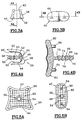
- the proximal element 38 is shown in Figures 1, 3A, 4A, and 5A.
- the profile of the head 39 of this proximal element is substantially at C, with an upper branch 42, corresponding to the dorsal face, longer than the lower branch 44, corresponding to the palmar side and a vertical branch 46.
- This profile is anatomically shaped to cooperate with the element distal 40.
- the lower branch on the palmar side is shorter to avoid contact with ligaments.
- the dorsal and palmar branches also have bosses 48 and 50 provided to cooperate with the grooves 24 of the housing 16.
- the proximal element 38 comprises an anchor 52, more particularly consisting of a rod 54 with notches 56 circumferential and two holes 58 and 60 oriented transversely by relative to the longitudinal axis of the rod and oriented at 90 ° to each other the other.
- the internal face 62 of the head 39 carries a grid 63 in relief, so as to allow a increased contact surface and better coverage by tissue after surgery.
- the distal element 40 shown in Figures 3B, 4B and 5B, includes a slightly concave head 64 and an anchor 66, more particularly a rod 68 with circumferential notches 70 in which four are formed holes 72, 74, 76 and 78, oriented on the one hand transversely to the longitudinal axis of the rod and on the other hand at 90 °, alternately, one by compared to others.
- the internal face 80 of the head 64 also carries a grid 82 in relief so as to allow an increase in the contact surface and a better coverage by the tissues of this internal face in contact with the bone material, after surgery.
- the internal face 80 comprises two immobilization pins 84, arranged on either side of the central rod 68, along a transverse axis.
- FIGS 6A and 6B there is shown a joint equipped with the implant according to the invention along planes, one parallel to the plane of the hand and the other perpendicular.
- FIG. 7 the same articulation has been shown but in a context in which the whole finger is shown with the pathway first 86, to explain the method of surgical intervention for putting in place of the implant according to the invention.
- the implantation method consists of accessing laterally the joint, incising on the side of the finger, more especially on the side oriented towards the thumb so as to be able to dislodge the part of the finger towards the outside, after having detached the lateral ligament made thus accessible by the incision.
- This intervention is a common operation that leaves little trauma because this lateral ligament is much less stressed than the extensor tendon.
- the choice of implant and the study of bone surfaces to work were carried out on a radio image, preferably life-size.
- each element of the implant includes a guide tracing 88 and 90, as shown in FIGS. 8A and 8B.
- Each of these guide includes a peripheral rod 92, 94 of marking whose cross section is shown enlarged in Figure 9 to show that the generator 96 of the rod intended to come into contact with the bone is shaped like a blade.
- Each rod is integral with a rigid wire frame 98, 100, which does not come in no case in contact with the bone, this frame being itself extended by a rod gripping 102, 104.
- An improvement of the invention proposes, as shown on the FIG. 10 an ergonomic handling tool 106, comprising a body 108 with two locations above 110 and below 112, offset along the longitudinal axis, to arrange the fingers as shown in Figure 11.
- Such a tool is intended to be attached to the gripping rod 102 or 104 tracing guides, which facilitates the work of the practitioner or his assistant.
- test guides 114, 116 to check progressively the milling progress.
- These test guides are shown in Figures 12A and 12B. They include proximal and distal test elements attached to a manipulation 106, said proximal and distal elements being provided without anchorage.
- drilling guides 118 and 120 shown in Figures 13A and 13B each include a template partially conforming to the profile of each of the proximal elements and distal of the implant and provided with at least one hole forming a piercing barrel.
- test guides 122, 124 including proximal and distal with anchor but these anchors are smooth with a diameter slightly smaller than the outside diameter of the final anchorage to allow a easy penetration and easy removal without degradation of the bore produced. For for practical reasons, these elements are also mounted on handling as described in figure 10.
- the practitioner can then permanently place the implant by introduction to gentle friction of the anchor until the heads are positioned perfectly in their homes.
- the practitioner then brings the dislocated finger part back into alignment natural, it hangs up the lateral ligament by any suitable known means, then it closes the way first by resorting to techniques known in surgery and adapted to this type of intervention.
- the practitioner performs, if necessary, a touch-up of the bone head in the presence of growths, due to disease, so that the functioning of the joint after placement of the implant is not disturbed.
- the external face of the distal element can advantageously be covered with a layer of highly abrasion-resistant material, such as a ceramic for example, which also facilitates the operation of the joint by reducing the coefficient of friction.
- proximal and distal elements are immobilized by their own form once mounted in the milling corresponding. Indeed, the proximal element is in C and the dorsal branches and palmar constitute a clamp.
- the distal element is embedded in its housing, the anti-rotation being obtained by the hollow housing and supplemented by immobilization pins 84.
- the ligaments do not suffer since they do not undergo any distension during the intervention.
- an anatomical implant In case of deeper destruction of surface elements articular, it is possible to use an anatomical implant by making vary the thickness of these elements to make up for the removed bone material or degraded.
- the proximal and distal elements are made of titanium / ceramic alloy but they can be chrome / cobalt, carbon titanium or with a coating of synthetic material such as a polymer.
- the invention also applies to condyles, shoulder, more generally at any joint of this type.
Abstract
Description
La présente invention a pour objet un implant métacarpo-phalangien ou métatarso-phalangien ou interphalangiens ainsi que l'ancillaire nécessaire.The present invention relates to a metacarpophalangeal implant or metatarsophalangeal or interphalangeal as well as the necessary ancillary.
De nombreuses maladies telles que l'arthrose ou les rhumatismes et/ou des accidents conduisent à des dégradations de l'articulation métacarpo-phalangienne ou métatarso-phalangienne ou interphalangiennnes, plus particulièrement à la destruction des cartilages de ces articulations.Many diseases such as osteoarthritis or rheumatism and / or accidents lead to damage to the metacarpophalangeal joint or metatarsophalangeal or interphalangeal, plus particularly the destruction of the cartilage of these joints.
Cette dégradation peut conduire à un handicap sérieux par limitation de l'angle de flexion autorisé par l'articulation.This deterioration can lead to a serious handicap by limitation of the angle of flexion authorized by the joint.
L'articulation métacarpo-phalangienne est du type condylien et possède deux degrés de liberté puisque le doigt peut se déplacer en flexion-extension, dans le plan sagittal et en inclinaison latérale, dans un plan frontal, lorsque les doigts sont en extension uniquement. En effet, lorsque le doigt est fléchi, les ligaments latéraux, par leur implantation excentrée, limitent et même interdisent les mouvements d'inclinaison latérale.The metacarpophalangeal joint is of the condylar type and has two degrees of freedom since the finger can move in flexion-extension, in the sagittal plane and in lateral inclination, in a frontal plane, when the fingers are extended only. When the finger is bent, the lateral ligaments, by their eccentric implantation, limit and even prohibit lateral tilting movements.
Les articulations interphalangiennes ne présentent qu'un seul degré de liberté dans le sens flexion-extension à l'exception de tout mouvement latéral.The interphalangeal joints have only one degree of freedom in the flexion-extension direction with the exception of any lateral movement.
En cas d'intervention, il convient que le résultat respecte ces différentes possibilités de mouvement mais également les amplitudes naturelles de ces mouvements. In case of intervention, the result should respect these different possibilities of movement but also the natural amplitudes of these movements.
On sait aussi que des tendons extenseurs disposés sur la face dorsale des doigts assurent les différents mouvements d'extension des doigts et l'accès par voie dorsale n'est pas souhaitable pour les interventions chirurgicales car ces tendons sont une gêne pour le praticien mais de plus le "décrochage" temporaire de ce tendon cause également des difficultés en ce sens qu'il oblige à une ouverture de dimensions beaucoup plus importantes et la réadaptation est plus longue car ce type de tendon est beaucoup plus sollicité.We also know that extensor tendons arranged on the dorsal side fingers ensure the different finger extension movements and back access is not desirable for procedures surgical because these tendons are an embarrassment for the practitioner but moreover the Temporary "detachment" of this tendon also causes difficulties in this sense that it requires an opening of much larger dimensions and rehabilitation is longer because this type of tendon is much more sought.
On connaít dans la demande de brevet européen EP O 455 929 des implants concernant le même domaine médico-chirurgical qui comprennent deux éléments distincts prévus pour coopérer en appui l'un sur l'autre et implantés respectivement l'un à l'extrémité du métacarpien et l'autre à l'extrémité en vis à vis de la première phalange ou aux extrémités en vis à vis de deux phalanges contiguës.We know in the European patent application EP O 455 929 implants relating to the same medical and surgical field which include two separate elements designed to cooperate in support of each other and implanted respectively one at the end of the metacarpal and the other at the opposite end of the first phalanx or the opposite ends of two contiguous phalanges.
On remarque que les deux éléments comprennent chacun un insert prévu pour pénétrer dans la matière spongieuse de l'os et une tête prévue pour former l'articulation proprement dite.Note that the two elements each include an insert intended to penetrate into the cancellous matter of the bone and a head provided for form the joint itself.
L'implantation est réalisée par intervention par voie dorsale, en fléchissant le doigt ou la phalange concernée pour permettre l'accès à l'articulation, ce qui est contraire à la méthode d'intervention préconisée.The implantation is carried out by intervention by dorsal route, in flexing the affected finger or phalanx to allow access to the joint, which is contrary to the recommended intervention method.
De plus, on remarque que l'implantation rend nécessaire une résection importante de chacun des os de l'articulation concernée, résection réalisée à l'aide d'une scie oscillante, à la limite des points d'attache des ligaments latéraux. Cette résection s'avère incontournable compte tenu de l'épaisseur de chacun des éléments de l'implant, généralement supérieure à l'épaisseur des cartilages dégradés.In addition, we note that the implantation necessitates a resection significant of each of the bones of the joint concerned, resection performed at using an oscillating saw, at the limit of the ligament attachment points side. This resection is essential given the thickness of each of the elements of the implant, generally greater than the thickness of the degraded cartilage.
De plus les têtes sont en réalité des coiffes qui viennent par dessus la surface d'extrémité de l'os concerné, après résection, avec un insert de grandes dimensions. On comprend en effet que cet insert soit de grandes dimensions pour éviter que la coiffe tourne d'une part, ce qui affaiblit la résistance de l'os car l'alésage va au-delà du canal médullaire, et que cet insert soit de forme conique d'autre part, pour permettre un bon ancrage, ce qui complique très sérieusement l'usinage avant implantation. De plus lesdits inserts ont une forme aplatie pour assurer un effet d'anti-rotation, plus exactement une forme de lame-palette trapézoïdale, implantable par impaction dans un trou de forme sensiblement correspondante, à réaliser préalablement, ice qui est une opération délicate nécessitant systématiquement un scellement complémentaire.In addition the heads are actually headdresses that come over the end surface of the affected bone, after resection, with an insert of large dimensions. We understand that this insert is large dimensions to prevent the cap from rotating on the one hand, which weakens the resistance of the bone because the bore goes beyond the medullary canal, and this insert either of conical shape on the other hand, to allow a good anchoring, which very seriously complicates the machining before implantation. Furthermore said inserts have a flattened shape to ensure an anti-rotation effect, more exactly a form of trapezoidal pallet blade, implantable by impaction in a hole of substantially corresponding shape, to be made beforehand, ice which is a delicate operation systematically requiring a sealing complementary.
L'inconvénient principal de cette méthode réside dans le fait que les os subissent une résection importante. Un autre inconvénient vient du fait que la itenue de chacun des éléments de l'implant est assurée par le seul blocage mécanique de l'insert, tant en rotation qu'en translation dans le sens de l'axe ilongitudinal de l'os sans que la tête participe à ce blocage. Seul l'insert assure l'immobilisation de chacun des éléments par rapport à l'os, il est donc le garant du bon fonctionnement de l'implant.The main disadvantage of this method is that the bones undergo an important resection. Another disadvantage is that the the location of each element of the implant is ensured by the sole blocking mechanics of the insert, both in rotation and in translation in the direction of the axis ilongitudinal of the bone without the head participating in this blockage. Only the insert ensures immobilization of each of the elements relative to the bone, so it's the ensuring the proper functioning of the implant.
Dans la demande de brevet européen EP-A-455.929 l'épaisseur des éléments de la prothèse doit être très réduite, malgré la résection et surtout pour essayer de la limiter et le scellement doit être très efficace afin d'éviter toute mobilité des éléments de la prothèse par rapport aux os qui les portent. Aussi, il est prévu dans ce brevet européen précité, une épaisseur d'au maximum 1 mm et préférentiellement 0,5 mm. De même, la rugosité est réduite à des excroissances de 5 µm et mieux encore 2,5 µm.In European patent application EP-A-455,929 the thickness of the elements of the prosthesis must be very reduced, despite resection and above all to try to limit it and the sealing must be very effective in order to avoid any mobility of the elements of the prosthesis relative to the bones which carry them. Also, it is provided in this aforementioned European patent, a thickness of at least maximum 1 mm and preferably 0.5 mm. Likewise, the roughness is reduced to 5 µm growths and better still 2.5 µm.
Une telle prothèse est très délicate à réaliser et son positionnement par rapport aux os sur lesquels elle est implantée reste aléatoire.Such a prosthesis is very delicate to produce and its positioning by relation to the bones on which it is implanted remains random.
On remarque également que cette demande ne prévoit aucune méthode d'implantation, ne résout pas le problème de l'accès dorsal ci-dessus évoqué et considéré comme préjudiciable à un bon fonctionnement ultérieur.We also note that this request does not provide any method of implantation, does not solve the problem of back access mentioned above and considered as prejudicial to a proper functioning later.
On connaít aussi par la demande de brevet allemand DE-A- 27 51 537, une prothèse de hanche qui présente une tête sphérique qui se loge dans un siège dit aussi condyle. Il s'agit d'une articulation dite condylienne au lieu d'une articulation trochléenne comme dans la présente invention.We also know from the German patent application DE-A- 27 51 537, a hip prosthesis which has a spherical head which is housed in a seat also says condyle. It is a so-called condylar joint instead of a trochlear joint as in the present invention.
Dans cette prothèse, il est prévu deux éléments, un premier qui est une coiffe venant se fixer sur la tête de fémur, en l'occurrence par vissage et un cotyle de profil conjugué de celui de la coiffe en sorte de coopérer et permettre une articulation. Ce cotyle est rapporté dans le logement naturel de l'os iliaque et simplement scellé car il est maintenu par l'appui de la tête de fémur. In this prosthesis, two elements are provided, a first which is a cap coming to be fixed on the femur head, in this case by screwing and a acetabular profile combined with that of the cap so as to cooperate and allow a joint. This acetabulum is reported in the natural housing of the iliac bone and simply sealed because it is held by the support of the femur head.
Le but de l'invention est de proposer un implant de resurfaçage intégré, l'ancillaire nécessaire ainsi qu'une méthode d'implantation chirurgicale afin de montrer tout l'intérêt de la présente invention et surtout pour montrer la réelle possibilité d'implantation d'un tel implant. Cet implant, selon l'invention vise à remplacer uniquement la partie cartilagineuse de l'articulation avec un traumatisme aussi réduit que possible pour le patient tout en autorisant une consolidation et une récupération rapide avec des degrés de flexion angulaire proches des valeurs naturelles. The object of the invention is to propose an integrated resurfacing implant, the necessary instruments and a method of surgical implantation in order to show all the interest of the present invention and especially to show the real possibility of implanting such an implant. This implant according to the invention aims to replace only the cartilaginous part of the joint with a trauma as low as possible for the patient while allowing consolidation and rapid recovery with degrees of angular flexion close to natural values.
Ce nouvel implant respecte les structures anatomiques et il est le garant d'une bonne stabilité articulaire, ce qui facilite aussi la récupération et diminue le temps de rééducation.This new implant respects the anatomical structures and is the guarantor good joint stability, which also facilitates recovery and reduces rehabilitation time.
De plus, la voie d'abord est latérale comme cela va être décrit, si bien que l'on mesure tout l'intérêt d'éviter une intervention sur le tendon extenseur, intervention qui peut être responsable par la suite d'adhérences nuisibles. Ce nouvel implant, l'ancillaire associé ainsi que la méthode mise en oeuvre permettent de préserver l'environnement ligamentaire.In addition, the approach route is lateral as will be described, so that we understand the importance of avoiding an intervention on the extensor tendon, intervention which may be responsible as a result of harmful adhesions. This new implant, the associated instrumentation and the method used help preserve the ligament environment.
A cet effet, selon l'invention, l'implant de resurfaçage évitant une résection osseuse, notamment pour une articulation métacarpo-phalangienne ou métatarso-phalangienne ou interphalangiennnes comprenant deux éléments proximal et distal, implantés respectivement à l'extrémité de chacun des os de l'articulation, composés chacun d'un ancrage et d'une tête d'articulation, se caractérise en ce que les têtes des éléments proximal et distal ont une épaisseur et un profil anatomique sensiblement identiques à ceux du cartilage en état, c'est à dire avant dégradation et sont prévues pour être encastrées dans un fraisage de l'os réalisé en fonction du profil desdites têtes, sensiblement en lieu et place desdits cartilages en sorte que les éléments de resurfaçage soient intégrés.To this end, according to the invention, the resurfacing implant avoiding a bone resection, especially for a metacarpophalangeal joint or metatarsophalangeal or interphalangeal comprising two elements proximal and distal, implanted respectively at the end of each of the bones of the joint, each composed of an anchor and a joint head, is characterized in that the heads of the proximal and distal elements have a thickness and anatomical profile substantially identical to that of cartilage in condition, that is to say before degradation and are intended to be embedded in a milling of the bone produced according to the profile of said heads, substantially in place of said cartilages so that the elements of resurfacing are integrated.
La tête de l'élément proximal a une section médiane longitudinale sensiblement en C, de façon à assurer un serrage élastique des faces de dessus et de dessous de l'os, la branche supérieure étant plus longue que la branche inférieure.The head of the proximal element has a longitudinal middle section substantially in C, so as to ensure an elastic clamping of the faces of above and below the bone, the upper branch being longer than the lower branch.
Il est aussi prévu des picots d'immobilisation, disposés de part et d'autre de l'ancrage de la tête de l'élément distal.It is also provided immobilization pins, arranged on the side and the anchoring of the head of the distal element.
Selon une autre caractéristique, l'ancrage comprend des tiges crantées circonférentiellement et munies chacune d'au moins un trou transversal pour une fixation par ostéo-intégration.According to another characteristic, the anchoring comprises notched rods circumferentially and each provided with at least one transverse hole for fixation by osseointegration.
Plus particulièrement, la face interne de chacune des têtes proximal et distal comporte un quadrillage d'accrochage des tissus.More particularly, the internal face of each of the proximal heads and distal has a grid for tissue attachment.
Quant à la face externe de la tête distale, elle peut être revêtue d'un matériau très résistant à l'abrasion tel qu'une céramique. As for the external face of the distal head, it can be coated with a very abrasion resistant material such as ceramic.
Dans un mode de réalisation particulier, les éléments proximal et distal sont réalisés en alliage de titane/céramique.In a particular embodiment, the proximal and distal elements are made of titanium / ceramic alloy.
L'invention a aussi pour objet l'ancillaire de mise en place de l'implant et cet ancillaire comprend, pour chacun des éléments proximal et distal, au moins l'un des éléments suivants :
- un guide de traçage,
- un guide d'essai de fraisage comprenant les têtes des éléments de l'implant sans ancrage,
- un guide de perçage, et/ou
- un guide d'essai de perçage comprenant les têtes des éléments de l'implant et des ancrages de plus petites dimensions non crantés.
- a tracing guide,
- a milling test guide including the heads of the implant elements without anchoring,
- a drilling guide, and / or
- a drilling test guide comprising the heads of the implant elements and smaller notched anchors.
Plus spécifiquement, le guide de traçage comprend un jonc au profil du fraisage à réaliser, solidaire d'un bâti prolongé par une tige de préhension, ce jonc ayant une génératrice en forme de lame, destinée à venir en contact avec l'os.More specifically, the tracing guide includes a rod with the profile of the milling to be carried out, integral with a frame extended by a gripping rod, this rod having a blade-shaped generator, intended to come into contact with the bone.
Le guide de perçage comprend une plaquette percée d'au moins un trou, adaptée à la forme du logement fraisé.The drilling guide comprises a plate pierced with at least one hole, adapted to the shape of the milled housing.
Selon un perfectionnement, les différents guides sont solidarisés à un outil de manipulation.According to an improvement, the different guides are secured to a manipulation tool.
La présente invention est décrite ci-après en regard des dessins annexés qui représentent un mode préférentiel de réalisation non limitatif et sur lesquels les figures suivantes montrent :
- la figure 1, une vue en perspective d'un même os dont chacune des deux extrémités est équipée de l'élément correspondant de l'implant selon l'invention,
- les figures 2A et 2B, une vue de face des extrémités de l'os après fraisage et avant mise en place des éléments de l'implant,
- les figures 3A et 3B, des vues de face respectivement de l'élément proximal et distal de l'implant selon l'invention,
- les figures 4A et 4B, des vues en coupe médiane respectivement par un plan vertical et par un plan horizontal de l'élément proximal et de l'élément distal selon l'invention,
- les figures 5A et 5B, des vues de la face arrière respectivement des éléments proximal et distal,
- les figures 6A et 6B sont des vues en coupe par un plan médian de l'articulation après pose des éléments proximal et distal de l'implant, respectivement par un plan horizontal, c'est à dire parallèle au plan de la main et par un plan vertical, c'est à dire par un plan perpendiculaire à celui de la main,
- la figure 7 est une vue d'un doigt avec la voie d'abord et l'articulation luxée permettant d'expliquer la méthode d'intervention,
- les figures 8A et 8B sont des vues en perspective des guides de traçage, respectivement des éléments proximal et distal,
- la figure 9 montre une vue en perspective d'une partie du jonc de traçage du guide de traçage,
- la figure 10 montre une vue en perspective d'un outil de manipulation ergonomique des guides,
- la figure 11 montre la prise en main de l'outil de manipulation représenté sur la figure 10,
- les figures 12A et 12B montrent respectivement les guides d'essai des éléments proximal et distal de l'implant sans ancrage, après fraisage,
- les figures 13A et 13B montrent respectivement les guides de perçage après fraisage, pour les éléments proximal et distal, et
- les figures 14A et 14B montrent respectivement les guides d'essai des éléments proximal et distal de l'implant avec ancrage, après perçage.
- FIG. 1, a perspective view of the same bone, each of the two ends of which is equipped with the corresponding element of the implant according to the invention,
- FIGS. 2A and 2B, a front view of the ends of the bone after milling and before placing the elements of the implant,
- FIGS. 3A and 3B, front views respectively of the proximal and distal element of the implant according to the invention,
- FIGS. 4A and 4B, views in median section respectively through a vertical plane and through a horizontal plane of the proximal element and of the distal element according to the invention,
- FIGS. 5A and 5B, views of the rear face respectively of the proximal and distal elements,
- FIGS. 6A and 6B are sectional views through a median plane of the joint after placement of the proximal and distal elements of the implant, respectively through a horizontal plane, that is to say parallel to the plane of the hand and by a vertical plane, that is to say by a plane perpendicular to that of the hand,
- FIG. 7 is a view of a finger with the approach and the dislocated joint making it possible to explain the method of intervention,
- FIGS. 8A and 8B are perspective views of the tracing guides, of the proximal and distal elements respectively,
- FIG. 9 shows a perspective view of part of the tracing rod of the tracing guide,
- FIG. 10 shows a perspective view of an ergonomic tool for handling the guides,
- FIG. 11 shows the handling of the manipulation tool represented in FIG. 10,
- FIGS. 12A and 12B respectively show the test guides for the proximal and distal elements of the implant without anchoring, after milling,
- FIGS. 13A and 13B respectively show the drilling guides after milling, for the proximal and distal elements, and
- FIGS. 14A and 14B respectively show the test guides for the proximal and distal elements of the implant with anchoring, after drilling.
Sur la figure 1, on a représenté une phalange 10, dont les extrémités
proximale 12 et distale 14 sont fraisées et portent respectivement un
logement en creux 1 6 à section sensiblement en C et un logement en creux 18
prévus pour recevoir les éléments proximal et distal de l'implant selon
l'invention. Pour des raisons de commodités, on a représenté les éléments
proximal et distal sur une même phalange pour montrer leur positionnement
respectif, mais il est bien entendu que les éléments sont en réalité portés
chacun par les extrémités en vis à vis de deux phalanges articulées entre elles.In Figure 1, there is shown a
Le logement 16, a un profil sensiblement en C, les branches
horizontales 20 et 22 de ce logement en C, c'est à dire les branches disposées
dans le plan de la main, comprennent latéralement, comme montré sur la
figure 2A, des rainures 24 qui se prolongent suivant l'axe longitudinal de la
phalange. La branche 26 verticale de ce logement en C est munie d'un trou
borgne 28, confondu sensiblement avec l'axe longitudinal de la phalange.The
Le logement 18 est en creux et comporte à sa périphérie une partie
osseuse résiduelle qui délimite ce logement en creux. Sensiblement au centre
de ce logement, il est prévu un trou borgne 30, l'axe de perçage étant
confondu avec l'axe longitudinal de la phalange.The
Il est en outre ménagé deux trous borgnes 32, complémentaires,
disposés de part et d'autre du trou central 30.There are also two
Les ligaments latéraux sont référencés 34.The lateral ligaments are referenced 34.
Sur cette figure 1, on a également représenté les éléments proximal 38
et distal 40 de l'implant selon l'invention.This FIG. 1 also shows the
L'élément proximal 38 est représenté sur les figures 1, 3A, 4A, et 5A.
Le profil de la tête 39 de cet élément proximal est sensiblement en C, avec
une branche supérieure 42, correspondant à la face dorsale, plus longue que la
branche inférieure 44, correspondant au côté palmaire et une branche verticale
46. Ce profil est conformé anatomiquement pour coopérer avec l'élément
distal 40. La branche inférieure du côté palmaire est plus courte pour éviter le
contact avec les ligaments.The
Les branches dorsale et palmaire comportent également des bossages
48 et 50 prévus pour coopérer avec les rainures 24 du logement 16.The dorsal and palmar branches also have
Ainsi que représenté sur la figure 4A, l'élément proximal 38 comprend
un ancrage 52, plus particulièrement constitué d'une tige 54 avec des crans
56 circonférentiels et deux trous 58 et 60 orientés transversalement par
rapport à l'axe longitudinal de la tige et orientés à 90° l'un par rapport à
l'autre.As shown in FIG. 4A, the
En se reportant à la figure 5A, on constate que la face interne 62 de la
tête 39 porte un quadrillage 63 en relief, de façon à permettre une
augmentation de la surface de contact et un meilleur recouvrement par les
tissus après l'intervention.Referring to FIG. 5A, it can be seen that the
L'élément distal 40, représenté sur les figures 3B, 4B et 5B, comprend
une tête 64, légèrement concave et un ancrage 66, plus particulièrement une
tige 68 avec des crans 70 circonférentiels dans laquelle sont ménagés quatre
trous 72, 74, 76 et 78, orientés d'une part transversalement par rapport à
l'axe longitudinal de la tige et d'autre part à 90°, alternativement, les uns par
rapport aux autres.The
La face interne 80 de la tête 64 porte également un quadrillage 82 en
relief de façon à permettre une augmentation de la surface de contact et une
meilleure couverture par les tissus de cette face interne en contact avec la
matière osseuse, après intervention.The
La face interne 80 comprend deux picots d'immobilisation 84, disposés
de part et d'autre de la tige centrale 68, suivant un axe transversal.The
Sur les figures 6A et 6B, on a représenté une articulation équipée de l'implant selon l'invention suivant des plans, l'un parallèle au plan de la main et l'autre perpendiculaire.In Figures 6A and 6B, there is shown a joint equipped with the implant according to the invention along planes, one parallel to the plane of the hand and the other perpendicular.
Sur la figure 7, on a représenté la même articulation mais dans un contexte dans lequel c'est le doigt entier qui est montré avec la voie d'abord 86, permettant d'expliquer la méthode d'intervention chirurgicale pour la mise en place de l'implant selon l'invention.In FIG. 7, the same articulation has been shown but in a context in which the whole finger is shown with the pathway first 86, to explain the method of surgical intervention for putting in place of the implant according to the invention.
En effet, la méthode d'implantation consiste à accéder latéralement à l'articulation, en incisant sur le côté du doigt, plus spécialement sur le côté orienté vers le pouce en sorte de pouvoir luxer la partie du doigt vers l'extérieur, après avoir détaché le ligament latéral rendu ainsi accessible par l'incision. Cet intervention est une opération courante qui laisse peu de traumatismes car ce ligament latéral est beaucoup moins sollicité que le tendon extenseur. Le choix de l'implant et l'étude des surfaces de l'os à travailler ont été effectués sur un cliché radio, de préférence grandeur nature.Indeed, the implantation method consists of accessing laterally the joint, incising on the side of the finger, more especially on the side oriented towards the thumb so as to be able to dislodge the part of the finger towards the outside, after having detached the lateral ligament made thus accessible by the incision. This intervention is a common operation that leaves little trauma because this lateral ligament is much less stressed than the extensor tendon. The choice of implant and the study of bone surfaces to work were carried out on a radio image, preferably life-size.
Après la luxation, le praticien procède au travail des extrémités des phalanges à l'aide de l'ancillaire qui est décrit ci-après.After the dislocation, the practitioner proceeds to work the ends of the phalanges using the ancillary which is described below.
Tout d'abord, après détermination de la taille d'implant à mettre en
place, le praticien procède dans une première étape au traçage des zones à
fraiser. Pour cela il utilise pour chaque élément de l'implant, un guide de
traçage 88 et 90, tel que représenté sur les figures 8A et 8B. Chacun de ces
guide comprend un jonc périphérique 92, 94 de marquage dont la section est
représentée agrandie sur la figure 9 pour montrer que la génératrice 96 du jonc
destinée à venir au contact de l'os est conformée en lame.First of all, after determining the implant size to be used
place, the practitioner proceeds in a first step to trace the areas to
milling. For this he uses for each element of the implant, a guide
tracing 88 and 90, as shown in FIGS. 8A and 8B. Each of these
guide includes a
Chaque jonc est solidaire d'un bâti filaire 98, 100 rigide, qui ne vient en
aucun cas en contact avec l'os, ce bâti étant lui-même prolongé par une tige
de préhension 102, 104.Each rod is integral with a
Un perfectionnement de l'invention propose, ainsi que montré sur la
figure 10 un outil de manipulation ergonomique 106, comprenant un corps
108 avec deux emplacements dessus 110 et dessous 112, décalés le long de
l'axe longitudinal, pour disposer les doigts ainsi que montré sur la figure 11.
Un tel outil est prévu pour être rapporté sur la tige de préhension 102 ou 104
des guides de traçage, ce qui facilite le travail du praticien ou de son assistant.An improvement of the invention proposes, as shown on the
FIG. 10 an
Par impaction ou par dépôt de bleu de méthylène dans lequel on trempe préalablement le jonc, le praticien marque l'os d'un tracé à suivre pour l'usinage.By impaction or by deposition of methylene blue in which one soaks before the rush, the practitioner marks the bone with a path to follow to machining.
Cette phase de traçage effectuée, le praticien fraise l'os sur une profondeur correspondant sensiblement à l'épaisseur de chacun des éléments de l'implant, dans l'espace délimité par le contour périphérique tracé. Il utilise pour cela du matériel connu couramment en service dans les services de chirurgie osseuse.This tracing phase carried out, the practitioner mills the bone on a depth corresponding substantially to the thickness of each of the elements of the implant, in the space delimited by the peripheral contour drawn. He uses for this known equipment commonly in use in the services of bone surgery.
En plus de l'habileté propre à chaque praticien, il est prévu des guides
d'essai 114, 116 pour contrôler au fur et à mesure l'avancement du fraisage.
Ces guides d'essai sont représentés sur les figures 12A et 12B. Ils
comprennent des éléments proximal et distal d'essai fixés sur un outil de
manipulation 106, lesdits éléments proximal et distal étant prévus sans
ancrage.In addition to the skill specific to each practitioner, there are
Après les différents essais et une fois les fraisages correctement réalisés, le praticien procède au perçage des trous destinés à recevoir les ancrages et à cet effet, il recourt aux guides de perçage 118 et 120 représentés sur les figures 13A et 13B. Ces guides comprennent chacun un gabarit conformé partiellement au profil de chacun des éléments proximal et distal de l'implant et muni d'au moins un trou formant canon de perçage.After the various tests and once the milling has been done correctly performed, the practitioner proceeds to drill the holes intended to receive the anchors and for this purpose it uses drilling guides 118 and 120 shown in Figures 13A and 13B. These guides each include a template partially conforming to the profile of each of the proximal elements and distal of the implant and provided with at least one hole forming a piercing barrel.
Il reste au praticien à vérifier la bonne réalisation du perçage au moyen des guides d'essai complets 122, 124 comprenant des éléments proximal et distal avec ancrage mais ces ancrages sont lisses avec un diamètre légèrement inférieur au diamètre extérieur de l'ancrage définitif pour autoriser une pénétration aisée et un retrait facile sans dégradation de l'alésage réalisé. Pour des raisons pratiques, ces éléments sont montés également sur des outils de manipulation tels que décrit sur la figure 10.It remains for the practitioner to verify the correct completion of the drilling by means complete test guides 122, 124 including proximal and distal with anchor but these anchors are smooth with a diameter slightly smaller than the outside diameter of the final anchorage to allow a easy penetration and easy removal without degradation of the bore produced. For for practical reasons, these elements are also mounted on handling as described in figure 10.
Le praticien peut alors poser définitivement l'implant par introduction à friction douce de l'ancrage jusqu'à ce que les têtes viennent se positionner parfaitement dans leurs logements.The practitioner can then permanently place the implant by introduction to gentle friction of the anchor until the heads are positioned perfectly in their homes.
Le praticien ramène ensuite la partie de doigt luxé dans l'alignement naturel, il raccroche le ligament latéral par tout moyen convenable connu, puis il ferme la voie d'abord en recourant à des techniques connues en chirurgie et adaptées à ce type d'intervention.The practitioner then brings the dislocated finger part back into alignment natural, it hangs up the lateral ligament by any suitable known means, then it closes the way first by resorting to techniques known in surgery and adapted to this type of intervention.
Durant l'opération de fraisage, le praticien procède, si besoin est, à une retouche de la tête d'os dans le cas de présence d'excroissances, dues à la maladie, afin que le fonctionnement de l'articulation après mise en place de l'implant ne soit pas perturbé.During the milling operation, the practitioner performs, if necessary, a touch-up of the bone head in the presence of growths, due to disease, so that the functioning of the joint after placement of the implant is not disturbed.
On remarque que les tendons fléchisseur et extenseur restent en position et ne sont pas concernés par l'intervention.We notice that the flexor and extensor tendons remain in position and are not affected by the intervention.
La face externe de l'élément distal peut être avantageusement recouverte d'une couche de matériau très résistant à l'abrasion, comme une céramique par exemple, qui facilite également le fonctionnement de l'articulation en diminuant le coefficient de frottement.The external face of the distal element can advantageously be covered with a layer of highly abrasion-resistant material, such as a ceramic for example, which also facilitates the operation of the joint by reducing the coefficient of friction.
On peut aussi remarquer que les éléments proximal et distal sont immobilisés par leur propre forme une fois montés dans le fraisage correspondant. En effet, l'élément proximal est en C et les branches dorsale et palmaire constituent une pince. L'élément distal est encastré dans son logement, l'anti-rotation étant obtenue par le logement en creux et complétée par les picots d'immobilisation 84. De plus, les ligaments ne souffrent pas puisqu'ils ne subissent aucune distension au cours de l'intervention.We can also notice that the proximal and distal elements are immobilized by their own form once mounted in the milling corresponding. Indeed, the proximal element is in C and the dorsal branches and palmar constitute a clamp. The distal element is embedded in its housing, the anti-rotation being obtained by the hollow housing and supplemented by immobilization pins 84. In addition, the ligaments do not suffer since they do not undergo any distension during the intervention.
La description qui vient d'être faite l'a été pour les articulations métacarpo-phalangiennes et interphalangiennes mais elle s'applique sans modification à des opérations sur les articulations métatarso-phalangiennes et interphalangiennes du pied. The description just made was for the joints metacarpophalangeal and interphalangeal but it applies without modification to operations on the metatarsophalangeal joints and interphalangeal feet.
En cas de destruction plus profonde des éléments des surfaces articulaires, il est possible de recourir à un implant anatomique en faisant varier l'épaisseur de ces éléments pour rattraper la matière osseuse retirée ou dégradée.In case of deeper destruction of surface elements articular, it is possible to use an anatomical implant by making vary the thickness of these elements to make up for the removed bone material or degraded.
Dans le mode de réalisation particulier qui vient d'être décrit, les éléments proximal et distal sont réalisés en alliage de titane/céramique mais ils peuvent être en chrome/cobalt, en titane carboné ou avec un revêtement en matériau de synthèse tel qu'un polymère.In the particular embodiment which has just been described, the proximal and distal elements are made of titanium / ceramic alloy but they can be chrome / cobalt, carbon titanium or with a coating of synthetic material such as a polymer.
L'invention s'applique également aux condyles, épaule, plus généralement à toute articulation de ce type.The invention also applies to condyles, shoulder, more generally at any joint of this type.
Claims (10)
- Resurfacing implant avoiding bone resection, for a joint made up of two bone ends, each of them with cartilage, such as a metacarpophalangeal or metatarsophalangeal or interphalangeal joint, said implant comprising two elements, namely a proximal element (12) and a distal element (40), which are implanted respectively at the end of each of the bones of this joint, each of these elements comprising an anchoring means (52, 66) and a joint head (39, 64), characterized in that the heads of the proximal and distal elements have a thickness and an anatomical profile substantially identical to those of the intact cartilage, that is to say of the cartilage before degradation, the head (39) of the proximal element (38) having a substantially C-shaped longitudinal section over the entire width of the articular surface of the implant, in such a way as to ensure elastic clamping of the top and bottom faces of the bone, the upper branch (42) being longer than the lower branch (44), and in that the heads are intended to be fitted in each case into a reamed recess in the bone, shaped to match the profile of said heads, in place of said cartilage, such that the resurfacing elements are integrated.
- Implant according to Claim 1, characterized in that the head (64) of the distal element (40) comprises immobilizing studs (84) arranged on each side of the anchoring means.
- Implant according to either of the preceding claims, characterized in that the anchoring means (52, 66) comprises rods (54, 68) notched circumferentially (56, 70) and each equipped with at least one transverse hole for fixation by osseointegration (58, 60; 72, 74, 76 and 78).
- Implant according to any one of the preceding claims, characterized in that the inner face (62, 80) of each of the heads of the proximal and distal elements comprises a gridwork (63, 82) for attachment of the tissues.
- Implant according to any one of the preceding claims, characterized in that the outer face of the distal head is coated with a material very resistant to abrasion, for example a ceramic.
- Implant according to any one of the preceding claims, characterized in that the proximal and distal elements are made of an alloy of titanium/ceramic.
- Ancillary for fitting the implant according to any one of Claims 1 to 6, characterized in that it comprises, for each of the proximal and distal elements, at least one of the following elements:a tracing guide (88, 90) with a rim (92, 94) having the profile of the reamed recess to be formed, and integral with a framework (98) continued by a grip rod (102, 104),a reaming test guide (114, 116) comprising the heads of the elements of the implant without anchoring means,a drilling guide (118, 120) and/ora drilling test guide (122, 124) comprising the heads of the elements of the implant according to Claim 1 and anchoring means of smaller dimensions and unnotched.
- Ancillary according to Claim 7, characterized in that the rim (92, 94) comprises a generatrix (96) of blade shape intended to come into contact with the bone.
- Ancillary according to Claim 7 or 8, characterized in that the drilling guide (118, 120) comprises a jig drilled with at least one hole, adapted to the shape of the reamed recess.
- Ancillary according to any one of Claims 7 to 9, characterized in that the different guides are connected to a manoeuvring tool (106).
Applications Claiming Priority (3)
| Application Number | Priority Date | Filing Date | Title |
|---|---|---|---|
| FR9414475A FR2727308B1 (en) | 1994-11-28 | 1994-11-28 | JOINT IMPLANT |
| FR9414475 | 1994-11-28 | ||
| PCT/FR1995/001563 WO1996016613A1 (en) | 1994-11-28 | 1995-11-27 | Joint implant and ancillary therefor |
Publications (2)
| Publication Number | Publication Date |
|---|---|
| EP0794746A1 EP0794746A1 (en) | 1997-09-17 |
| EP0794746B1 true EP0794746B1 (en) | 2004-07-14 |
Family
ID=9469393
Family Applications (1)
| Application Number | Title | Priority Date | Filing Date |
|---|---|---|---|
| EP95941148A Expired - Lifetime EP0794746B1 (en) | 1994-11-28 | 1995-11-27 | Joint implant and ancillary therefor |
Country Status (6)
| Country | Link |
|---|---|
| EP (1) | EP0794746B1 (en) |
| AT (1) | ATE270863T1 (en) |
| AU (1) | AU4264696A (en) |
| DE (1) | DE69533263D1 (en) |
| FR (1) | FR2727308B1 (en) |
| WO (1) | WO1996016613A1 (en) |
Families Citing this family (3)
| Publication number | Priority date | Publication date | Assignee | Title |
|---|---|---|---|---|
| DE19820748A1 (en) * | 1998-05-08 | 1999-11-11 | Moje Hans Juergen | Joint surface replacement for fingers or toes |
| DE19820749A1 (en) * | 1998-05-08 | 1999-11-11 | Moje Hans Juergen | Joint surface replacement for small hinge joints |
| US8608741B2 (en) | 2008-08-01 | 2013-12-17 | Skeletal Dynamics, Llc | Internal joint stabilizer device, system and method of use |
Family Cites Families (8)
| Publication number | Priority date | Publication date | Assignee | Title |
|---|---|---|---|---|
| DE2751537A1 (en) * | 1977-11-18 | 1979-05-23 | Wolfgang Bongartz | Hip prosthesis ball and socket joint - has ceramic or ceramic covered internally corrugated spherical part and socket part |
| FR2594323B1 (en) * | 1986-02-18 | 1995-10-20 | Matco | CEMENT-FREE BALL JOINT PROSTHESIS |
| FR2629339B1 (en) * | 1988-04-01 | 1997-09-12 | Broc Christian | LAYING MATERIAL FOR PARTICULARLY A TIBIAL AND / OR FEMORAL ELEMENT OF A BI-COMPARTMENTAL KNEE JOINT PROSTHESIS |
| DE3917285A1 (en) * | 1989-05-27 | 1990-11-29 | Wolfgang Roth | Shoulder prosthesis - has condyle and acetabulum made of specified material |
| US4997445A (en) * | 1989-12-08 | 1991-03-05 | Zimmer, Inc. | Metal-backed prosthetic implant with enhanced bonding of polyethylene portion to metal base |
| DE9005372U1 (en) * | 1990-05-11 | 1991-09-26 | Thera Patent Gmbh & Co. Kg Gesellschaft Fuer Industrielle Schutzrechte, 8031 Seefeld, De | |
| FR2676641B1 (en) * | 1990-11-29 | 1994-09-16 | Vialla Jean Marie | FEMOROPATLLARY PROSTHESIS. |
| FR2699068B1 (en) * | 1992-12-14 | 1995-03-10 | Laboureau Jacques Philippe | Ancillary equipment for the placement of a femoro-patellar prosthesis. |
-
1994
- 1994-11-28 FR FR9414475A patent/FR2727308B1/en not_active Expired - Fee Related
-
1995
- 1995-11-27 AT AT95941148T patent/ATE270863T1/en not_active IP Right Cessation
- 1995-11-27 EP EP95941148A patent/EP0794746B1/en not_active Expired - Lifetime
- 1995-11-27 WO PCT/FR1995/001563 patent/WO1996016613A1/en active IP Right Grant
- 1995-11-27 AU AU42646/96A patent/AU4264696A/en not_active Abandoned
- 1995-11-27 DE DE69533263T patent/DE69533263D1/en not_active Expired - Lifetime
Also Published As
| Publication number | Publication date |
|---|---|
| DE69533263D1 (en) | 2004-08-19 |
| ATE270863T1 (en) | 2004-07-15 |
| AU4264696A (en) | 1996-06-19 |
| EP0794746A1 (en) | 1997-09-17 |
| FR2727308A1 (en) | 1996-05-31 |
| WO1996016613A1 (en) | 1996-06-06 |
| FR2727308B1 (en) | 1997-06-06 |
Similar Documents
| Publication | Publication Date | Title |
|---|---|---|
| EP1952771B1 (en) | Surgical instrument assembly for inserting a shoulder prosthesis | |
| EP0127503B1 (en) | Shoulder prosthesis | |
| EP2385812B1 (en) | Intramedullary anchoring stem for an orthopaedic implant head | |
| EP1813230B1 (en) | Chirurgical instumentation kit for placing a dowel prosthesis. | |
| US5669913A (en) | Method and apparatus for smoothing an anatomical joint bearing surface during hemi-joint replacement | |
| EP2243444B1 (en) | Device for fixation of a joint cup for a shoulder prosthesis and corresponding shoulder prosthesis | |
| EP1529493B1 (en) | Implantable orthese and surgical kit for the arthrodesis of knee | |
| EP1398006A2 (en) | Duo-fixation prosthetic joints | |
| EP1477143A1 (en) | Prosthetic kit for a tibial-prosthetic assembly | |
| FR2634373A1 (en) | Total knee prosthesis | |
| WO2004100838A1 (en) | Composite shoulder prosthesis | |
| FR2681240A1 (en) | TOTAL WRIST PROSTHESIS. | |
| FR2660856A1 (en) | Lower radioulnar prosthesis | |
| EP0524874A1 (en) | Joint prosthesis, especially trapezoid-metacarpal and digital joint | |
| WO2005053579A1 (en) | Postero-lateral intervertebral disc prosthesis | |
| EP2276427B1 (en) | Trapezio-metacarpal joint prosthesis | |
| WO2010023399A1 (en) | Set of ancillaries for implanting a knee prosthesis | |
| WO2009122085A2 (en) | Cutting element for a tool for shaping a bone surface, and tool provided with same | |
| EP0794746B1 (en) | Joint implant and ancillary therefor | |
| EP0639360A1 (en) | Finger articulation prosthesis with one dish shaped element | |
| EP2687189B1 (en) | Interpositional trapezium implant | |
| FR2945436A1 (en) | SURGICAL INSTRUMENTATION OF BONE DISTRACTION OF THE SHOULDER | |
| EP1566147A1 (en) | Ancillary for the preparation of the femur for a minimally invasive hip arthroplasty | |
| FR2916961A1 (en) | Complete prosthesis for reversed shoulder of patient, has protection unit covering lateral surface of bone graft, which is not in contact with cord, and forming support for part of opposite surface of glenoidal component | |
| FR2628316A1 (en) | Whole knee prosthesis - has one piece implanted at end of femur, other at end of tibia articulating around cross member of T=piece |
Legal Events
| Date | Code | Title | Description |
|---|---|---|---|
| PUAI | Public reference made under article 153(3) epc to a published international application that has entered the european phase |
Free format text: ORIGINAL CODE: 0009012 |
|
| 17P | Request for examination filed |
Effective date: 19970628 |
|
| AK | Designated contracting states |
Kind code of ref document: A1 Designated state(s): AT BE CH DE DK ES FR GB IE IT LI NL SE |
|
| 17Q | First examination report despatched |
Effective date: 19970911 |
|
| GRAP | Despatch of communication of intention to grant a patent |
Free format text: ORIGINAL CODE: EPIDOSNIGR1 |
|
| GRAS | Grant fee paid |
Free format text: ORIGINAL CODE: EPIDOSNIGR3 |
|
| GRAA | (expected) grant |
Free format text: ORIGINAL CODE: 0009210 |
|
| AK | Designated contracting states |
Kind code of ref document: B1 Designated state(s): AT BE CH DE DK ES FR GB IE IT LI NL SE |
|
| PG25 | Lapsed in a contracting state [announced via postgrant information from national office to epo] |
Ref country code: NL Free format text: LAPSE BECAUSE OF FAILURE TO SUBMIT A TRANSLATION OF THE DESCRIPTION OR TO PAY THE FEE WITHIN THE PRESCRIBED TIME-LIMIT Effective date: 20040714 Ref country code: IT Free format text: LAPSE BECAUSE OF FAILURE TO SUBMIT A TRANSLATION OF THE DESCRIPTION OR TO PAY THE FEE WITHIN THE PRE;WARNING: LAPSES OF ITALIAN PATENTS WITH EFFECTIVE DATE BEFORE 2007 MAY HAVE OCCURRED AT ANY TIME BEFORE 2007. THE CORRECT EFFECTIVE DATE MAY BE DIFFERENT FROM THE ONE RECORDED.SCRIBED TIME-LIMIT Effective date: 20040714 Ref country code: IE Free format text: LAPSE BECAUSE OF FAILURE TO SUBMIT A TRANSLATION OF THE DESCRIPTION OR TO PAY THE FEE WITHIN THE PRESCRIBED TIME-LIMIT Effective date: 20040714 Ref country code: GB Free format text: LAPSE BECAUSE OF FAILURE TO SUBMIT A TRANSLATION OF THE DESCRIPTION OR TO PAY THE FEE WITHIN THE PRESCRIBED TIME-LIMIT Effective date: 20040714 Ref country code: AT Free format text: LAPSE BECAUSE OF FAILURE TO SUBMIT A TRANSLATION OF THE DESCRIPTION OR TO PAY THE FEE WITHIN THE PRESCRIBED TIME-LIMIT Effective date: 20040714 |
|
| REG | Reference to a national code |
Ref country code: GB Ref legal event code: FG4D Free format text: NOT ENGLISH |
|
| REG | Reference to a national code |
Ref country code: CH Ref legal event code: EP |
|
| REF | Corresponds to: |
Ref document number: 69533263 Country of ref document: DE Date of ref document: 20040819 Kind code of ref document: P |
|
| REG | Reference to a national code |
Ref country code: IE Ref legal event code: FG4D Free format text: FRENCH |
|
| PG25 | Lapsed in a contracting state [announced via postgrant information from national office to epo] |
Ref country code: SE Free format text: LAPSE BECAUSE OF FAILURE TO SUBMIT A TRANSLATION OF THE DESCRIPTION OR TO PAY THE FEE WITHIN THE PRESCRIBED TIME-LIMIT Effective date: 20041014 Ref country code: DK Free format text: LAPSE BECAUSE OF FAILURE TO SUBMIT A TRANSLATION OF THE DESCRIPTION OR TO PAY THE FEE WITHIN THE PRESCRIBED TIME-LIMIT Effective date: 20041014 |
|
| PG25 | Lapsed in a contracting state [announced via postgrant information from national office to epo] |
Ref country code: DE Free format text: LAPSE BECAUSE OF FAILURE TO SUBMIT A TRANSLATION OF THE DESCRIPTION OR TO PAY THE FEE WITHIN THE PRESCRIBED TIME-LIMIT Effective date: 20041015 |
|
| PG25 | Lapsed in a contracting state [announced via postgrant information from national office to epo] |
Ref country code: ES Free format text: LAPSE BECAUSE OF FAILURE TO SUBMIT A TRANSLATION OF THE DESCRIPTION OR TO PAY THE FEE WITHIN THE PRESCRIBED TIME-LIMIT Effective date: 20041025 |
|
| PG25 | Lapsed in a contracting state [announced via postgrant information from national office to epo] |
Ref country code: LI Free format text: LAPSE BECAUSE OF NON-PAYMENT OF DUE FEES Effective date: 20041130 Ref country code: CH Free format text: LAPSE BECAUSE OF NON-PAYMENT OF DUE FEES Effective date: 20041130 Ref country code: BE Free format text: LAPSE BECAUSE OF NON-PAYMENT OF DUE FEES Effective date: 20041130 |
|
| NLV1 | Nl: lapsed or annulled due to failure to fulfill the requirements of art. 29p and 29m of the patents act | ||
| GBV | Gb: ep patent (uk) treated as always having been void in accordance with gb section 77(7)/1977 [no translation filed] |
Effective date: 20040714 |
|
| REG | Reference to a national code |
Ref country code: IE Ref legal event code: FD4D |
|
| PLBE | No opposition filed within time limit |
Free format text: ORIGINAL CODE: 0009261 |
|
| STAA | Information on the status of an ep patent application or granted ep patent |
Free format text: STATUS: NO OPPOSITION FILED WITHIN TIME LIMIT |
|
| BERE | Be: lapsed |
Owner name: LABORATOIRE DE PROTHESE DENTAIRE CHIBRAC S.A. Effective date: 20041130 |
|
| 26N | No opposition filed |
Effective date: 20050415 |
|
| REG | Reference to a national code |
Ref country code: CH Ref legal event code: PL |
|
| BERE | Be: lapsed |
Owner name: S.A. LABORATOIRE DE PROTHESE DENTAIRE *CHIBRAC Effective date: 20041130 |
|
| PGFP | Annual fee paid to national office [announced via postgrant information from national office to epo] |
Ref country code: FR Payment date: 20141125 Year of fee payment: 20 |