EP2262544B1 - Gefässbehandlungsmaschine - Google Patents
Gefässbehandlungsmaschine Download PDFInfo
- Publication number
- EP2262544B1 EP2262544B1 EP09726079A EP09726079A EP2262544B1 EP 2262544 B1 EP2262544 B1 EP 2262544B1 EP 09726079 A EP09726079 A EP 09726079A EP 09726079 A EP09726079 A EP 09726079A EP 2262544 B1 EP2262544 B1 EP 2262544B1
- Authority
- EP
- European Patent Office
- Prior art keywords
- valve
- gas
- liquid
- chamber
- fluid
- Prior art date
- Legal status (The legal status is an assumption and is not a legal conclusion. Google has not performed a legal analysis and makes no representation as to the accuracy of the status listed.)
- Not-in-force
Links
Images
Classifications
-
- A—HUMAN NECESSITIES
- A61—MEDICAL OR VETERINARY SCIENCE; HYGIENE
- A61L—METHODS OR APPARATUS FOR STERILISING MATERIALS OR OBJECTS IN GENERAL; DISINFECTION, STERILISATION OR DEODORISATION OF AIR; CHEMICAL ASPECTS OF BANDAGES, DRESSINGS, ABSORBENT PADS OR SURGICAL ARTICLES; MATERIALS FOR BANDAGES, DRESSINGS, ABSORBENT PADS OR SURGICAL ARTICLES
- A61L2/00—Disinfection or sterilisation of materials or objects, in general; Accessories therefor
- A61L2/16—Disinfection or sterilisation of materials or objects, in general; Accessories therefor using chemical substances
- A61L2/18—Liquid substances
- A61L2/186—Peroxide solutions
-
- A—HUMAN NECESSITIES
- A61—MEDICAL OR VETERINARY SCIENCE; HYGIENE
- A61L—METHODS OR APPARATUS FOR STERILISING MATERIALS OR OBJECTS IN GENERAL; DISINFECTION, STERILISATION OR DEODORISATION OF AIR; CHEMICAL ASPECTS OF BANDAGES, DRESSINGS, ABSORBENT PADS OR SURGICAL ARTICLES; MATERIALS FOR BANDAGES, DRESSINGS, ABSORBENT PADS OR SURGICAL ARTICLES
- A61L2/00—Disinfection or sterilisation of materials or objects, in general; Accessories therefor
- A61L2/16—Disinfection or sterilisation of materials or objects, in general; Accessories therefor using chemical substances
- A61L2/20—Gaseous substances, e.g. vapours
- A61L2/208—Hydrogen peroxide
-
- A—HUMAN NECESSITIES
- A61—MEDICAL OR VETERINARY SCIENCE; HYGIENE
- A61L—METHODS OR APPARATUS FOR STERILISING MATERIALS OR OBJECTS IN GENERAL; DISINFECTION, STERILISATION OR DEODORISATION OF AIR; CHEMICAL ASPECTS OF BANDAGES, DRESSINGS, ABSORBENT PADS OR SURGICAL ARTICLES; MATERIALS FOR BANDAGES, DRESSINGS, ABSORBENT PADS OR SURGICAL ARTICLES
- A61L2/00—Disinfection or sterilisation of materials or objects, in general; Accessories therefor
- A61L2/24—Apparatus using programmed or automatic operation
-
- B—PERFORMING OPERATIONS; TRANSPORTING
- B01—PHYSICAL OR CHEMICAL PROCESSES OR APPARATUS IN GENERAL
- B01D—SEPARATION
- B01D27/00—Cartridge filters of the throw-away type
- B01D27/08—Construction of the casing
-
- B—PERFORMING OPERATIONS; TRANSPORTING
- B01—PHYSICAL OR CHEMICAL PROCESSES OR APPARATUS IN GENERAL
- B01D—SEPARATION
- B01D27/00—Cartridge filters of the throw-away type
- B01D27/10—Safety devices, e.g. by-passes
- B01D27/103—Bypass or safety valves
-
- B—PERFORMING OPERATIONS; TRANSPORTING
- B01—PHYSICAL OR CHEMICAL PROCESSES OR APPARATUS IN GENERAL
- B01D—SEPARATION
- B01D27/00—Cartridge filters of the throw-away type
- B01D27/10—Safety devices, e.g. by-passes
- B01D27/106—Anti-leakage or anti-return valves
-
- B—PERFORMING OPERATIONS; TRANSPORTING
- B01—PHYSICAL OR CHEMICAL PROCESSES OR APPARATUS IN GENERAL
- B01D—SEPARATION
- B01D35/00—Filtering devices having features not specifically covered by groups B01D24/00 - B01D33/00, or for applications not specifically covered by groups B01D24/00 - B01D33/00; Auxiliary devices for filtration; Filter housing constructions
- B01D35/30—Filter housing constructions
- B01D35/306—Filter mounting adapter
-
- B—PERFORMING OPERATIONS; TRANSPORTING
- B65—CONVEYING; PACKING; STORING; HANDLING THIN OR FILAMENTARY MATERIAL
- B65B—MACHINES, APPARATUS OR DEVICES FOR, OR METHODS OF, PACKAGING ARTICLES OR MATERIALS; UNPACKING
- B65B55/00—Preserving, protecting or purifying packages or package contents in association with packaging
- B65B55/02—Sterilising, e.g. of complete packages
- B65B55/04—Sterilising wrappers or receptacles prior to, or during, packaging
- B65B55/10—Sterilising wrappers or receptacles prior to, or during, packaging by liquids or gases
-
- A—HUMAN NECESSITIES
- A61—MEDICAL OR VETERINARY SCIENCE; HYGIENE
- A61L—METHODS OR APPARATUS FOR STERILISING MATERIALS OR OBJECTS IN GENERAL; DISINFECTION, STERILISATION OR DEODORISATION OF AIR; CHEMICAL ASPECTS OF BANDAGES, DRESSINGS, ABSORBENT PADS OR SURGICAL ARTICLES; MATERIALS FOR BANDAGES, DRESSINGS, ABSORBENT PADS OR SURGICAL ARTICLES
- A61L2103/00—Materials or objects being the target of disinfection or sterilisation
- A61L2103/23—Containers other than laboratory or medical, e.g. bottles or mail
-
- B—PERFORMING OPERATIONS; TRANSPORTING
- B01—PHYSICAL OR CHEMICAL PROCESSES OR APPARATUS IN GENERAL
- B01D—SEPARATION
- B01D2201/00—Details relating to filtering apparatus
- B01D2201/34—Seals or gaskets for filtering elements
Definitions
- the invention relates to a vessel treatment machine for the sterilization of containers by means of a sterilizing liquid, comprising at least one liquid supply line and one or more gas supply lines, further comprising at least one mixing chamber for producing a liquid / gas mixture, and at least one valve in the liquid supply line ,
- Such a vessel treatment machine will be broadly in the WO 03/030950 A1 described. Similar embodiments are the subject of DE 10 2004 029 803 B4 ,
- the vessel treatment machine is usually one that is used in the beverage industry, ie when bottling drinks, cans or generally containers made of, for example, plastic, metal, glass, etc. is used.
- liquid hydrogen peroxide H 2 O 2
- H 2 O 2 liquid hydrogen peroxide
- this liquid / gas mixture or hydrogen peroxide / air mixture may be fed to an evaporator, in which the still liquid H 2 O 2 is completely evaporated.
- the invention is based on the technical problem of further developing a vessel treatment machine for the sterilization of containers by means of a sterilization liquid such that the sterilization liquid is available in precisely metered and reproducible quantities within the mixing chamber.
- the mixing chamber and an output side valve chamber of the valve coincide functional.
- the valve chamber which is obligatory in the liquid feed line at the outlet of the valve is also used as a mixing chamber, ie. H. for the preparation of the liquid / gas mixture.
- the entering into the mixing chamber or the valve chamber gas automatically ensures that the valve chamber is flushed as it were, in the desired mixing ratio.
- the gas supply line for the supply of the gas usually opens directly into the output-side valve chamber. That is, the valve chamber is used for atomizing the liquid / gas mixture and thus emptied after each stroke.
- Such a stroke corresponds to the required amount of liquid and gas, which is required for the treatment of most of a container. Since both the sterilization liquid and the gas are supplied under pressure and the gas supply line is equipped with a valve, can be provided by appropriate control of the valves for the respective production of the liquid / gas mixture within the mixing chamber or valve chamber. This liquid / gas mixture is then fed to the treatment head, in which usually the already described evaporation process and thus the activation of the sterilization liquid. The activated sterilization liquid or the Mixture is finally injected into the container. This completes a hub or stroke.
- the metering process takes place completely within the outlet-side valve chamber of the valve in the liquid feed line, the metering or the metering process is separated from the evaporation process and thus not time-critical.
- the metered amount for the sterilization liquid can be specified particularly sensitively, for example in the sense of a regulation. It is always ensured that the subsequently leaving the output side valve chamber or mixing chamber liquid / gas mixture is precisely adapted to the container to be treated.
- valve body within the valve in the liquid supply line opens an opening between an input-side valve chamber and the output-side valve chamber more or less. If the position of the valve body is interrogated in this process, the amount of sterilizing fluid metered into the outlet-side valve chamber can be specified exactly in the sense of a regulation. This happens until the amount of sterilizing liquid present in this way in the outlet-side valve chamber is sufficient for the treatment of the associated container and the subsequent atomization with the aid of the gas.
- valve body between the two valve chambers may be closed and then the valve in the gas supply line can be opened to atomize the existing within the output-side valve chamber amount of sterilizing liquid. Because this process takes place directly in the outlet-side valve chamber, which also acts as a mixing chamber, it is ensured that all liquid constituents of the sterilization liquid are included in the liquid / gas mixture in the described atomization process. Any dead volumes as in the prior art are not observed.
- the output-side valve chamber of the valve located in the liquid supply line respectively control valve directly to a treatment head to join.
- the liquid / gas mixture generated in the output-side valve chamber is fed to a further second mixing chamber, which in turn is then connected to the treatment head.
- the mixing process takes place in two stages, by first the liquid / gas mixture in the output-side valve chamber or first mixing chamber is prepared and then this liquid / gas mixture is transferred to another second mixing chamber, which (also) with another second gas supply is applied.
- the further second mixing chamber is fed by the further second gas supply line and a chamber feed line, which connects the first mixing chamber or output-side valve chamber to the second mixing chamber.
- the gas supply line is equipped with a Venturi nozzle or generally a nozzle on the input side of the (respective) mixing chamber.
- a control valve it is also in the valve in the gas supply line to a control valve, so such a valve in which detects the position of a valve body and can be adjusted in the sense of a regulation so that exactly the desired amount of metered Gas or dosed liquid (in the control valve in the liquid supply line) leaves the valve.
- the sterilizing liquid is liquid hydrogen peroxide, but this is not considered mandatory.
- the gas used is mostly sterile air, ie air that has been previously sterilized.
- the subject of the invention is also a process for the sterilization of containers according to claim 10. The described process can be carried out in the vessel treatment machine explained in detail. This is not mandatory.
- a vessel treatment machine which serves for the sterilization of containers 1.
- container 1 may be a plastic PET bottle, which of course is not to be understood as limiting.
- the sterilization takes place with the aid of a liquid / gas mixture which may be activated in a container head 2, as described in detail in US Pat DE 10 2004 029 803 B4 is described.
- the container head 2 is equipped with, for example, a heat exchanger, which ensures that the sterilization liquid is activated in the example case.
- the sterilizing liquid is present and not limited to liquid hydrogen peroxide, which is supplied in total via a liquid feed line 3.
- This sterilizing liquid or the liquid hydrogen peroxide is mixed with a gas (sterile air), which is supplied by means of a gas supply line 4.
- a valve 5 is provided, which is designed as a control valve.
- the gas supply line 4 has a valve 6, which is also designed as a control valve 6. Both control valves 5, 6 are connected to a common control unit 7, which interrogates the position of their respective valve body, in order to control a metered amount of sterilizing liquid on the output side of the valve 5 and otherwise a metered amount of gas on the output side of the valve 6 available put.
- the gas is not limited to sterile air.
- valve or control valve 5 is equipped with an input-side valve chamber 7a and an output-side valve chamber 7b, which are separated from each other by a valve body.
- the amount of sterilizing liquid within the output-side valve chamber 7b is predetermined, namely - as described - in the sense of a control, which is checked and specified by means of the control unit 7.
- the valve body is generally closed and the valve 6 is opened thereafter.
- the output-side valve chamber 7b also performs the function of a mixing chamber 7b for producing the liquid / gas mixture or in the atomization of the sterilization liquid in the interior of the output-side valve chamber 7b with the help of the supplied gas. That is, the mixing chamber 7b and the output side valve chamber 7b are functionally coincident. It can be seen that in the variant according to the Fig. 1 the outlet-side valve chamber or mixing chamber 7b is connected directly to the treatment head 2, namely via an outlet line 8. By contrast, in the variant according to Fig. 2 realized another mixing chamber 9.
- the gas supply line 4 divides after the valve 6 into two separate gas supply lines 4a, 4b, which in the respective mixing chambers 7b and 9 in the variant of the Fig. 2 lead.
- the mixing chamber 7b or output-side valve chamber 7b of the valve 5 assumes the function of a first mixing chamber 7b, whereas the further mixing chamber 9 acts as a second mixing chamber.
- the liquid / gas mixture generated within the first mixing chamber 7b is fed via a chamber feed line 10 into the second mixing chamber 9 and here undergoes a further mixture in such a way that the further gas feed line 4b is connected to the second mixing chamber 9.
- a Venturi nozzle 11 on the input side of the second mixing chamber 9 ensures that the gas supplied via the gas feed line 4b into the mixing chamber 9 experiences an acceleration, so that the atomization in the second mixing chamber 9 is intensified.
- the second mixing chamber 9 is connected directly to the treatment head 2, which of course is not to be regarded as mandatory.
- the treatment head 2 may itself be part of a rotary or linear machine, as is well known.
- the sterilization liquid within the liquid feed 3 additionally takes advantage of the natural gradient because the flow direction of the sterilization liquid follows the force of gravity.
- optimal degassing of the sterilization liquid can be achieved before it is mixed with the gas in the mixing chamber or first mixing chamber 7b. This ensures that that the liquid / gas mixture practically composed only of the two constituents of the sterilizing liquid and the gas (sterile air).
Landscapes
- Health & Medical Sciences (AREA)
- Chemical Kinetics & Catalysis (AREA)
- Chemical & Material Sciences (AREA)
- Public Health (AREA)
- Epidemiology (AREA)
- Life Sciences & Earth Sciences (AREA)
- Animal Behavior & Ethology (AREA)
- General Health & Medical Sciences (AREA)
- Veterinary Medicine (AREA)
- General Chemical & Material Sciences (AREA)
- Engineering & Computer Science (AREA)
- Mechanical Engineering (AREA)
- Apparatus For Disinfection Or Sterilisation (AREA)
- Nozzles (AREA)
- Crushing And Grinding (AREA)
- Electrical Discharge Machining, Electrochemical Machining, And Combined Machining (AREA)
- Crystals, And After-Treatments Of Crystals (AREA)
Description
- Die Erfindung betrifft eine Gefäßbehandlungsmaschine zur Sterilisation von Behältern mittels einer Sterilisationsflüssigkeit, mit wenigstens einer Flüssigkeits-Zuleitung und einer oder mehreren Gas-Zuleitungen, ferner mit zumindest einer Mischkammer zur Herstellung eines Flüssigkeits-/Gasgemisches, und mit wenigstens einem Ventil in der Flüssigkeits-Zuleitung.
- Eine solche Gefäßbehandlungsmaschine wird im Großen und Ganzen in der
WO 03/030950 A1 DE 10 2004 029 803 B4 . Bei der Gefäßbehandlungsmaschine handelt es sich regelmäßig um eine solche, die in der Getränkeindustrie eingesetzt wird, d. h. beim Abfüllen von Getränken in Flaschen, Dosen oder allgemein Behältern aus beispielsweise Kunststoff, Metall, Glas usw. zum Einsatz kommt. - Meistens sind solche Gefäßbehandlungsmaschinen einer Abfüllanlage vorgeschaltet und dienen dazu, die erforderliche Keimfreiheit innerhalb des Behälters und damit die Haltbarkeit des abgefüllten Produktes sicherzustellen. Zu diesem Zweck wird regelmäßig flüssiges Wasserstoffperoxid (H2O2) als Sterilisationsflüssigkeit fein verstäubt einem Luftstrom in der Mischkammer beigemischt. Im Anschluss daran mag dieses Flüssigkeits-/Gasgemisch bzw. Wasserstoffperoxid-/Luftgemisch einem Verdampfer zugeführt werden, in welchem das noch flüssige H2O2 vollständig verdampft wird.
- Tatsächlich ist es nämlich für die Aktivierung des Wasserstoffperoxides, d. h. für seine Zersetzung, erforderlich, dieses auf eine bestimmte Temperatur zu erwärmen. Bei dieser Temperatur zerfällt das Wasserstoffperoxid in Wasser und freie Radikale, welche für die eigentliche Sterilisation verantwortlich zeichnet. Das hat sich bewährt, und zwar auch bei der Sterilisation von Pappbehältern, wie dies grundsätzlich in der
US 6 120 730 beschrieben wird. - Die einwandfreie Sterilisation des Behälters setzt voraus, dass die Sterilisationsflüssigkeit wohl dosiert zur Verfügung gestellt wird. Das geschieht meistens mit Hilfe des in der Flüssigkeits-Zuleitung vorhandenen wenigstens einen Ventils. Allerdings ergibt sich hier das Problem, dass die vom Ventil an beispielsweise eine Zerstäubungseinrichtung weitergeleitete Flüssigkeitsmenge von Fall zu Fall variieren kann. Diese variierende Flüssigkeitsmenge erklärt sich aufgrund von in dem Ventil verbleibender Sterilisationsflüssigkeit von einem zum anderen Abgabezyklus an einen Behandlungskopf. Darüber hinaus müssen eventuelle weitere sogenannte "Totmengen" in einer Zuleitung vom Ventil zur Mischkammer bzw. bis hin zum Zerstäuber berücksichtigt werden. - Hier setzt die Erfindung ein.
- Der Erfindung liegt das technische Problem zugrunde, eine Gefäßbehandlungsmaschine zur Sterilisation von Behältern mittels einer Sterilisationsflüssigkeit so weiter zu entwickeln, dass die Sterilisationsflüssigkeit in exakt dosierbaren und reproduzierbaren Mengen innerhalb der Mischkammer zur Verfügung steht.
- Zur Lösung dieser technischen Problemstellung ist bei einer gattungsgemäßen Gefäßbehandlungsmaschine vorgesehen, dass die Mischkammer und eine ausgangsseitige Ventilkammer des Ventils funktional zusammenfallen. D. h., die am Ausgang des Ventils in der Flüssigkeits-Zuleitung obligatorische Ventilkammer wird zugleich als Mischkammer genutzt, d. h. für die Herstellung des Flüssigkeits-/Gasgemisches.
- Auf diese Weise sorgt das in die Mischkammer bzw. die Ventilkammer eintretende Gas automatisch dafür, dass die Ventilkammer gleichsam gespült wird, und zwar in dem gewünschten Mischungsverhältnis. Dazu mündet die Gas-Zuleitung für die Zufuhr des Gases üblicherweise unmittelbar in die ausgangsseitige Ventilkammer. D. h., die Ventilkammer wird zur Verdüsung des Flüssigkeits-/Gasgemisches genutzt und dadurch nach jedem Hub entleert.
- Ein solcher Hub korrespondiert zur erforderlichen Menge an Flüssigkeit und Gas, die für die Behandlung meistens eines Behälters erforderlich ist. Da sowohl die Sterilisationsflüssigkeit als auch das Gas unter Druck zugeführt werden und auch die Gas-Zuleitung mit einem Ventil ausgerüstet ist, kann durch entsprechende Ansteuerung der Ventile für die jeweilige Herstellung des Flüssigkeits-/Gasgemisches innerhalb der Mischkammer respektive Ventilkammer gesorgt werden. Dieses Flüssigkeits-/Gasgemisch wird danach dem Behandlungskopf zugeführt, in dem in der Regel der bereits beschriebene Verdampfungsvorgang und damit die Aktivierung der Sterilisationsflüssigkeit erfolgt. Die aktivierte Sterilisationsflüssigkeit bzw. das Gemisch wird abschließend in den Behälter eingeblasen. Damit ist ein Hub bzw. Arbeitshub beendet.
- Da erfindungsgemäß der Dosiervorgang vollständig innerhalb der die Mischkammer darstellenden ausgangsseitigen Ventilkammer des Ventils in der Flüssigkeits-Zuleitung stattfindet, ist die Dosierung bzw. der Dosiervorgang vom Verdampfungsvorgang getrennt und somit nicht zeitkritisch. Dadurch kann die Dosiermenge für die Sterilisationsflüssigkeit besonders feinfühlig vorgegeben werden, beispielsweise im Sinne einer Regelung. Immer ist gewährleistet, dass das anschließend die ausgangsseitige Ventilkammer bzw. Mischkammer verlassende Flüssigkeits-/Gasgemisch zielgenau an den zu behandelnden Behälter angepasst ist.
- Das mag im Detail dergestalt erfolgen, dass ein Ventilkörper innerhalb des Ventils in der Flüssigkeits-Zuleitung eine Öffnung zwischen einer eingangsseitigen Ventilkammer und der ausgangsseitigen Ventilkammer mehr oder minder öffnet. Wenn bei diesem Vorgang die Stellung des Ventilkörpers abgefragt wird, kann die in die ausgangsseitige Ventilkammer dosierte Menge an Sterilisationsflüssigkeit exakt im Sinne einer Regelung vorgegeben werden. Das geschieht solange, bis die auf diese Weise in der ausgangsseitigen Ventilkammer vorhandene Menge der Sterilisationsflüssigkeit für die Behandlung des zugehörigen Behälters und die anschließende Verdüsung mit Hilfe des Gases ausreichend ist.
- Dann mag der Ventilkörper zwischen den beiden Ventilkammern geschlossen werden und kann anschließend das Ventil in der Gaszuleitung geöffnet werden, um die innerhalb der ausgangsseitigen Ventilkammer vorhandene Menge an Sterilisationsflüssigkeit zu verdüsen. Weil dieser Vorgang unmittelbar in der ausgangsseitigen Ventilkammer stattfindet, die zugleich als Mischkammer fungiert, ist sichergestellt, dass bei dem beschriebenen Verdüsungsvorgang sämtliche Flüssigkeitsbestandteile der Sterilisationsflüssigkeit Eingang in das Flüssigkeits-/Gasgemisch finden. Etwaige Totmengen wie beim Stand der Technik werden nicht beobachtet.
- Weitere vorteilhafte Ausgestaltungen werden im Folgenden beschrieben. So ist es denkbar, die ausgangsseitige Ventilkammer des in der Flüssigkeits-Zuleitung befindlichen Ventils respektive Regelventils unmittelbar an einen Behandlungskopf anzuschließen. Es ist aber auch möglich, dass das in der ausgangsseitigen Ventilkammer erzeugte Flüssigkeits-/Gasgemisch einer weiteren zweiten Mischkammer zugeführt wird, die dann ihrerseits an den Behandlungskopf angeschlossen ist. D. h., der Mischvorgang findet zweistufig statt, indem zunächst das Flüssigkeits-/Gasgemisch in der ausgangsseitigen Ventilkammer bzw. ersten Mischkammer hergestellt wird und dann dieses Flüssigkeits-/Gasgemisch in eine weitere zweite Mischkammer überführt wird, die (ebenfalls) mit einer weiteren zweiten Gaszuleitung beaufschlagt wird. Dadurch kann der Verdüsungsvorgang optimiert werden. D.h., in diesem Fall wird die weitere zweite Mischkammer von der weiteren zweiten Gaszuleitung und einer Kammerzuleitung gespeist, welche die erste Mischkammer bzw. ausgangsseitige Ventilkammer mit der zweiten Mischkammer verbindet.
- Um den Mischvorgang noch weiter zu beschleunigen, ist es denkbar, dass die Gas-Zuleitung mit einer Venturidüse oder allgemein einer Düse eingangsseitig der (jeweiligen) Mischkammer ausgerüstet ist. - Wie bereits erläutert, handelt es sich auch bei dem Ventil in der Gas-Zuleitung um ein Regelventil, also ein solches Ventil, bei dem die Stellung eines Ventilkörpers erfasst und im Sinne einer Regelung so eingestellt werden kann, dass exakt die gewünschte Menge an dosiertem Gas bzw. dosierter Flüssigkeit (beim Regelventil in der Flüssigkeits-Zuleitung) das Ventil verlässt.
- Im Allgemeinen handelt es sich bei der Sterilisationsflüssigkeit um flüssiges Wasserstoffperoxid, was jedoch nicht als zwingend anzusehen ist. Als Gas kommt überwiegend Sterilluft zum Einsatz, also Luft, die zuvor sterilisiert worden ist. - Gegenstand der Erfindung ist auch ein Verfahren zur Sterilisation von Behältern nach Anspruch 10. Das beschriebene Verfahren kann dabei in der im Detail erläuterten Gefäßbehandlungsmaschine durchgeführt werden. Das ist jedoch nicht zwingend.
- Im Folgenden wird die Erfindung anhand einer lediglich ein Ausführungsbeispiel darstellenden Zeichnung näher erläutert; es zeigen:
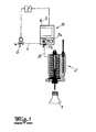
- Fig. 1
- eine erfindungsgemäße Gefäßbehandlungsmaschine, reduziert auf die für die Erfindung wesentlichen Bestandteile in einer ersten Ausgestaltung und
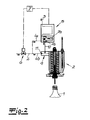
- Fig. 2
- den Gegenstand nach
Fig. 1 in einer Variante. - In den Figuren ist eine Gefäßbehandlungsmaschine dargestellt, die zur Sterilisation von Behältern 1 dient. Bei dem lediglich in
Fig. 1 angedeuteten Behälter 1 mag es sich um eine Kunststoff-PET-Flasche handeln, was selbstverständlich nicht einschränkend zu verstehen ist. Die Sterilisation erfolgt mit Hilfe eines Flüssigkeits-/Gasgemisches, welches in einem Behälterkopf 2 aktiviert werden mag, wie dies im Detail in derDE 10 2004 029 803 B4 beschrieben wird. Dazu ist der Behälterkopf 2 mit beispielsweise einem Wärmetauscher ausgerüstet, welcher dafür sorgt, dass die Sterilisationsflüssigkeit im Beispielfall aktiviert wird. - Tatsächlich handelt es sich bei der Sterilisationsflüssigkeit vorliegend und nicht einschränkend um flüssiges Wasserstoffperoxid, welches insgesamt über eine Flüssigkeits-Zuleitung 3 zugeführt wird. Diese Sterilisationsflüssigkeit bzw. das flüssige Wasserstoffperoxid wird mit einem Gas (Sterilluft) gemischt, welches mit Hilfe einer Gas-Zuleitung 4 zugeführt wird. Innerhalb der Flüssigkeits-Zuleitung 3 ist ein Ventil 5 vorgesehen, welches als Regelventil ausgestaltet ist. Auch die Gas-Zuleitung 4 verfügt über ein Ventil 6, das ebenfalls als Regelventil 6 ausgelegt ist. Beide Regelventile 5, 6 sind an eine gemeinsame Steuereinheit 7 angeschlossen, welche die Stellung ihrer jeweiligen Ventilkörper abfragt, um im Sinne einer Regelung eine dosierte Menge an Sterilisationsflüssigkeit ausgangsseitig des Ventils 5 und im Übrigen eine dosierte Menge an Gas ausgangsseitig des Ventils 6 zur Verfügung zu stellen. Bei dem Gas handelt es sich nicht einschränkend um Sterilluft.
- Man erkennt, dass das Ventil bzw. Regelventil 5 mit einer eingangsseitigen Ventilkammer 7a und einer ausgangsseitigen Ventilkammer 7b ausgerüstet ist, die voneinander durch einen Ventilkörper getrennt sind. Je nach Stellung dieses Ventilkörpers wird die Menge an Sterilisationsflüssigkeit innerhalb der ausgangsseitigen Ventilkammer 7b vorgegeben, und zwar - wie beschrieben - im Sinne einer Regelung, die mit Hilfe der Steuereinheit 7 überprüft und vorgegeben wird. Sobald in der ausgangsseitigen Ventilkammer 7b die erforderliche dosierte Menge an Sterilisationsflüssigkeit vorhanden ist, wird im Allgemeinen der Ventilkörper geschlossen und im Anschluss hieran das Ventil 6 geöffnet.
- Da die Gas-Zuleitung 4 an die ausgangsseitige Ventilkammer 7b angeschlossen ist bzw. in diese mündet, übernimmt die ausgangsseitige Ventilkammer 7b zugleich die Funktion einer Mischkammer 7b zur Herstellung des Flüssigkeits-/Gasgemisches bzw. bei der Verdüsung der Sterilisationsflüssigkeit im Innern der ausgangsseitigen Ventilkammer 7b mit Hilfe des zugeführten Gases. D. h., die Mischkammer 7b und die ausgangsseitige Ventilkammer 7b fallen funktional zusammen. Man erkennt, dass im Rahmen der Variante nach der
Fig. 1 die ausgangsseitige Ventilkammer bzw. Mischkammer 7b unmittelbar an den Behandlungskopf 2 angeschlossen ist, nämlich über eine Ausgangsleitung 8. Dagegen ist bei der Variante nachFig. 2 eine weitere Mischkammer 9 realisiert. - Tatsächlich teilt sich die Gas-Zuleitung 4 nach dem Ventil 6 in zwei separate Gas-Zuleitungen 4a, 4b, die in die jeweiligen Mischkammern 7b respektive 9 bei der Variante nach der
Fig. 2 münden. Dabei übernimmt die Mischkammer 7b bzw. ausgangsseitige Ventilkammer 7b des Ventils 5 die Funktion einer ersten Mischkammer 7b, wohingegen die weitere Mischkammer 9 als zweite Mischkammer fungiert. Das innerhalb der ersten Mischkammer 7b erzeugte Flüssigkeits-/Gasgemisch wird über eine Kammerzuleitung 10 in die zweite Mischkammer 9 gespeist und erfährt hier eine weitere Mischung dergestalt, dass die weitere Gas-Zuleitung 4b an die zweite Mischkammer 9 angeschlossen ist. - Dabei sorgt eine Venturidüse 11 eingangsseitig der zweiten Mischkammer 9 dafür, dass das über die Gas-Zuleitung 4b in die Mischkammer 9 zugeführte Gas eine Beschleunigung erfährt, so dass die Verdüsung in der zweiten Mischkammer 9 intensiviert wird. Die zweite Mischkammer 9 ist unmittelbar an den Behandlungskopf 2 angeschlossen, was selbstverständlich nicht als zwingend anzusehen ist. Der Behandlungskopf 2 mag selbst Bestandteil einer Rundläufer- oder Linearmaschine sein, wie dies allgemein bekannt ist.
- Man erkennt schlussendlich, dass die Sterilisationsflüssigkeit innerhalb der Flüssigkeits-Zuieitung 3 zusätzlich das natürliche Gefälle ausnutzt, weil die Flussrichtung der Sterilisationsflüssigkeit der Schwerkraft folgt. Dadurch lässt sich eine optimale Entgasung der Sterilisationsflüssigkeit erreichen, bevor diese mit dem Gas in der Mischkammer bzw. ersten Mischkammer 7b gemischt wird. Dadurch ist gewährleistet, dass sich das Flüssigkeits-/Gasgemisch praktisch nur aus den beiden Bestandteilen der Sterilisationsflüssigkeit und dem Gas (Sterilluft) zusammensetzt.
Claims (10)
- Gefäßbehandlungsmaschine zur Sterilisation von Behältern (1) mittels einer Sterilisationsflüssigkeit, mit wenigstens einer Flüssigkeits-Zuleitung (3) und einer oder mehreren Gas-Zuleitungen (4; 4a, 4b), ferner mit zumindest einer Mischkammer (7b) zur Herstellung eines Flüssigkeits-/Gasgemisches, und mit wenigstens einem Ventil (5) in der Flüssigkeits-Zuleitung (3), dadurch ge-kennzeichnet, dass die Mischkammer (7b) und eine ausgangsseitige Ventilkammer (7b) des Ventils (5) funktional zusammenfallen.
- Gefäßbehandlungsmaschine nach Anspruch 1, dadurch gekennzeichnet, dass die Gas-Zuleitung (4; 4a, 4b) in die ausgangsseitige Ventilkammer (7b) mündet.
- Gefäßbehandlungsmaschine nach Anspruch 1 oder 2, dadurch gekennzeichnet, dass die ausgangsseitige Ventilkammer (7b) unmittelbar an einen Behandlungskopf (2) angeschlossen ist.
- Gefäßbehandlungsmaschine nach einem der Ansprüche 1 bis 3, dadurch gekennzeichnet, dass die ausgangsseitige Ventilkammer (7b) unter Zwischenschaltung einer weiteren zweiten Mischkammer (9) an den Behandlungskopf (2) angeschlossen ist.
- Gefäßbehandlungsmaschine nach Anspruch 4, dadurch gekennzeichnet, dass die weitere zweite Mischkammer (9) von einer weiteren zweiten Gaszuleitung (4b) und einer Kammerzuleitung (10) gespeist wird.
- Gefäßbehandlungsmaschine nach einem der Ansprüche 1 bis 5, dadurch gekennzeichnet, dass die Gas-Zuleitung (4; 4a, 4b) eine Venturidüse (11) zur Beschleunigung der Fließgeschwindigkeit des Gases aufweist.
- Gefäßbehandlungsmaschine nach einem der Ansprüche 1 bis 6, dadurch gekennzeichnet, dass das Ventil (5) in der Flüssigkeits-Zuleitung (3) als Regelventil ausgeführt ist.
- Gefäßbehandlungsmaschine nach einem der Ansprüche 1 bis 7, dadurch gekennzeichnet, dass die Gas-Zuleitung (4) ein Ventil (6), insbesondere Regelventil (6), aufweist.
- Gefäßbehandlungsmaschine nach einem der Ansprüche 1 bis 8, dadurch gekennzeichnet, dass die Sterilisationsflüssigkeit als flüssiges H2O2 und das Gas als Sterilluft ausgebildet ist.
- Verfahren zur Sterilisation von Behältern (1) mittels eines Flüssigkeits-/Gasgemisches aus einer Sterilisationsflüssigkeit und einem Gas, wonach mittels eines Ventils (5) in einer Flüssigkeits-Zuleitung (3) die Sterilisationsflüssigkeit dosiert wird, dadurch gekennzeichnet, dass das Gas mit der Sterilisationsflüssigkeit in einer ausgangsseitigen Ventilkammer (7b) des Ventils (5) gemischt wird.
Priority Applications (1)
| Application Number | Priority Date | Filing Date | Title |
|---|---|---|---|
| PL09726079T PL2262544T3 (pl) | 2008-03-25 | 2009-03-10 | Maszyna do obróbki pojemników |
Applications Claiming Priority (2)
| Application Number | Priority Date | Filing Date | Title |
|---|---|---|---|
| DE102008015675A DE102008015675A1 (de) | 2008-03-25 | 2008-03-25 | Gefäßbehandlungsmaschine |
| PCT/EP2009/001697 WO2009118096A1 (de) | 2008-03-25 | 2009-03-10 | Gefässbehandlungsmaschine |
Publications (2)
| Publication Number | Publication Date |
|---|---|
| EP2262544A1 EP2262544A1 (de) | 2010-12-22 |
| EP2262544B1 true EP2262544B1 (de) | 2011-08-17 |
Family
ID=40674946
Family Applications (1)
| Application Number | Title | Priority Date | Filing Date |
|---|---|---|---|
| EP09726079A Not-in-force EP2262544B1 (de) | 2008-03-25 | 2009-03-10 | Gefässbehandlungsmaschine |
Country Status (6)
| Country | Link |
|---|---|
| US (1) | US8790576B2 (de) |
| EP (1) | EP2262544B1 (de) |
| AT (1) | ATE520423T1 (de) |
| DE (1) | DE102008015675A1 (de) |
| PL (1) | PL2262544T3 (de) |
| WO (1) | WO2009118096A1 (de) |
Families Citing this family (5)
| Publication number | Priority date | Publication date | Assignee | Title |
|---|---|---|---|---|
| JP6473057B2 (ja) * | 2015-07-23 | 2019-02-20 | 三菱重工機械システム株式会社 | 殺菌剤の気化方法及び気化装置 |
| KR20240133776A (ko) | 2017-03-27 | 2024-09-04 | 리제너론 파아마슈티컬스, 인크. | 살균 방법 |
| US10287369B2 (en) * | 2017-04-24 | 2019-05-14 | Chevron Phillips Chemical Company Lp | Methods of preparing a catalyst |
| MA54325A (fr) | 2019-06-05 | 2022-05-11 | Regeneron Pharma | Dispositifs et procédés pour l'administration précise de doses |
| USD1120314S1 (en) | 2022-11-30 | 2026-03-24 | Regeneron Pharmaceuticals, Inc. | Dose delivery device |
Family Cites Families (12)
| Publication number | Priority date | Publication date | Assignee | Title |
|---|---|---|---|---|
| DE1566670A1 (de) * | 1967-06-24 | 1970-04-30 | Medizintechnik Leipzig Veb | Verdampfer fuer Narkosegeraete mit bei normaler Temperatur fluessigen Narkosemitteln |
| DE3809852A1 (de) | 1988-03-24 | 1989-10-05 | Seitz Enzinger Noll Masch | Verfahren zum aseptischen bzw. sterilen abfuellen von fluessigem fuellgut in behaelter sowie vorrichtung zum durchfuehren dieses verfahrens |
| IT1223719B (it) | 1988-07-22 | 1990-09-29 | Robino E Galandrino Spa | Dispositivo dosatore particolarmente per il dosaggio delle sostanze sterilizzanti impiegate nel trattamento di sterilizzazione di bottiglie e contenitori in genere |
| SE463240B (sv) * | 1989-11-07 | 1990-10-29 | Tetra Pak Holdings & Finance | Saett att framstaella gasformigt, vaeteperoxidinnehaallande steriliseringsfluidum |
| RU2132752C1 (ru) * | 1998-04-13 | 1999-07-10 | Научно-исследовательский институт низких температур при МАИ (Московском государственном авиационном институте - техническом университете) | Устройство для создания газокапельной струи и клапан для подачи двухфазной рабочей среды |
| US6120730A (en) | 1998-06-26 | 2000-09-19 | Tetra Laval Holdings & Finance, Sa | Heat and hydrogen peroxide gas sterilization of container |
| DE10013150A1 (de) * | 2000-03-17 | 2001-10-04 | Wilfried Wiegers | Vorrichtung zum Austragen eines verwirbelten Gemisches aus einer Flüssigkeit, der ggf. ein Wirkstoff zugegeben ist und Gas |
| DE10114758B4 (de) | 2001-03-20 | 2013-01-31 | Ptm Packaging Tools Machinery Pte. Ltd. | Verfahren zum Sterilisieren von Behältern |
| US6752959B2 (en) | 2001-10-05 | 2004-06-22 | Pepsico, Inc. | High-speed, low temperature sterilization and sanitization apparatus and method |
| DE10346843B4 (de) * | 2002-12-03 | 2018-03-01 | Robert Bosch Gmbh | Vorrichtung zum Vergasen eines Dekontaminationsmittels |
| CH696801A5 (de) * | 2002-12-03 | 2007-12-14 | Bosch Gmbh Robert | Vorrichtung zum Vergasen eines Dekontaminationsmittel. |
| DE102004029803B4 (de) | 2004-06-19 | 2007-01-11 | Khs Ag | Gefäßbehandlungsmaschine zur Sterilisation von Behältern mittels H2O2 |
-
2008
- 2008-03-25 DE DE102008015675A patent/DE102008015675A1/de not_active Ceased
-
2009
- 2009-03-10 EP EP09726079A patent/EP2262544B1/de not_active Not-in-force
- 2009-03-10 PL PL09726079T patent/PL2262544T3/pl unknown
- 2009-03-10 AT AT09726079T patent/ATE520423T1/de active
- 2009-03-10 US US12/920,896 patent/US8790576B2/en not_active Expired - Fee Related
- 2009-03-10 WO PCT/EP2009/001697 patent/WO2009118096A1/de not_active Ceased
Also Published As
| Publication number | Publication date |
|---|---|
| PL2262544T3 (pl) | 2012-01-31 |
| US20110020176A1 (en) | 2011-01-27 |
| WO2009118096A1 (de) | 2009-10-01 |
| US8790576B2 (en) | 2014-07-29 |
| DE102008015675A1 (de) | 2009-10-01 |
| ATE520423T1 (de) | 2011-09-15 |
| EP2262544A1 (de) | 2010-12-22 |
Similar Documents
| Publication | Publication Date | Title |
|---|---|---|
| EP2181374B1 (de) | Dosier- und versorgungssystem für vorrichtungen zum h2o2-sterilisieren von packmitteln sowie vorrichtung mit einem solchen dosier- und versorgungssystem | |
| EP2049275B1 (de) | Verfahren zur sterilisation von reinräumen für die behandlung und/oder das füllen und verschliessen von behältern | |
| EP1614433B1 (de) | Verfahren zum Sterilisieren von Flaschen oder dgl. Behälter sowie Sterilisator zum Durchführen des Verfahrens | |
| EP2850029B2 (de) | Behältnisherstellungsanlage mit bodenkühlung der behältnisse | |
| WO2009118096A1 (de) | Gefässbehandlungsmaschine | |
| DE69316409T2 (de) | Verfahren zur Transformierung eines Flüssigkeitsstromes in einen Gasstrom und Vorrichtung zur Durchführung dieses Verfahrens | |
| DE102004029803B4 (de) | Gefäßbehandlungsmaschine zur Sterilisation von Behältern mittels H2O2 | |
| EP3834954A1 (de) | Vorrichtung zum befüllen eines behälters mit cip-reinigung | |
| DE102007039008A1 (de) | Dosier- und Versorgungssystem für Vorrichtungen zum H2O2-Sterilisieren von Packmitteln, Vorrichtung mit einem solchen Dosier- und Versorgungssystem sowie Verfahren zum Betrieb einer solchen Vorrichtung | |
| WO2009043715A1 (de) | Verfahren zur dosierung von dialkydicarbonaten in getränke | |
| EP2214724A1 (de) | Vorrichtung und verfahren zum erzeugen eines sterilisierenden gasgemischs | |
| CH696801A5 (de) | Vorrichtung zum Vergasen eines Dekontaminationsmittel. | |
| EP2446336B1 (de) | Anlage und verfahren zur kontinuierlichen herstellung eines flüssigkeitsgemisches | |
| EP2407182A1 (de) | Vorrichtung zum Sterilisieren von Behältnissen | |
| DE102009011054A1 (de) | Verfahren zur Behandlung von Flaschen oder Behältern mit einem Wasserstoffperoxid enthaltenden Behandlungsmedium | |
| EP0900761B1 (de) | Verfahren zur Herstellung und Abfüllung von mit Sauerstoff oder einem Sauerstoff-Gasgemisch angereicherten Flüssigkeiten sowie Getränk | |
| DE102011104873B4 (de) | Verfahren sowie Behandlungskopf zum Behandeln von Behältern | |
| EP2299853B1 (de) | Pasteurisierungsanlage | |
| EP4292441B1 (de) | Vorrichtung und verfahren zum konservieren von getränken | |
| DE102010040703B4 (de) | Vorrichtung und Verfahren zum Behandeln von Getränken | |
| DE102010025690A1 (de) | Verfahren und Anlage zur Herstellung von Fluidgemischen, z.B. Getränken | |
| AT408406B (de) | Verfahren zur herstellung und abfüllung von mit sauerstoff oder einem sauerstoff-gasgemisch angereicherten flüssigkeiten | |
| WO1998005415A1 (de) | Verfahren und anlage zum einbringen eines gases in eine flüssigkeit | |
| WO2002036250A1 (de) | Vorrichtung zum herstellen von mit sauerstoff angereicherter flüssigkeit | |
| EP4588882A1 (de) | Behälterbehandlungsanlage sowie verfahren zum betrieb |
Legal Events
| Date | Code | Title | Description |
|---|---|---|---|
| PUAI | Public reference made under article 153(3) epc to a published international application that has entered the european phase |
Free format text: ORIGINAL CODE: 0009012 |
|
| 17P | Request for examination filed |
Effective date: 20101025 |
|
| AK | Designated contracting states |
Kind code of ref document: A1 Designated state(s): AT BE BG CH CY CZ DE DK EE ES FI FR GB GR HR HU IE IS IT LI LT LU LV MC MK MT NL NO PL PT RO SE SI SK TR |
|
| AX | Request for extension of the european patent |
Extension state: AL BA RS |
|
| RIN1 | Information on inventor provided before grant (corrected) |
Inventor name: KIEFER, MARGIT Inventor name: BAUER, EVA Inventor name: STUWE, HANS, PETER Inventor name: STANISLAWSKI, ANDREAS Inventor name: NEUMANN, BERND Inventor name: KLEISS, ANDREAS Inventor name: BEHRENDT, FRANK, PETER |
|
| RIN1 | Information on inventor provided before grant (corrected) |
Inventor name: STANISLAWSKI, ANDREAS Inventor name: KIEFER, MARGIT Inventor name: BEHRENDT, FRANK, PETER Inventor name: BAUER, EVA Inventor name: STUWE, HANS, PETER Inventor name: NEUMANN, BERND Inventor name: KLEISS, ANDREAS |
|
| GRAP | Despatch of communication of intention to grant a patent |
Free format text: ORIGINAL CODE: EPIDOSNIGR1 |
|
| DAX | Request for extension of the european patent (deleted) | ||
| GRAS | Grant fee paid |
Free format text: ORIGINAL CODE: EPIDOSNIGR3 |
|
| GRAA | (expected) grant |
Free format text: ORIGINAL CODE: 0009210 |
|
| AK | Designated contracting states |
Kind code of ref document: B1 Designated state(s): AT BE BG CH CY CZ DE DK EE ES FI FR GB GR HR HU IE IS IT LI LT LU LV MC MK MT NL NO PL PT RO SE SI SK TR |
|
| REG | Reference to a national code |
Ref country code: GB Ref legal event code: FG4D Free format text: NOT ENGLISH |
|
| REG | Reference to a national code |
Ref country code: CH Ref legal event code: EP |
|
| REG | Reference to a national code |
Ref country code: IE Ref legal event code: FG4D Free format text: LANGUAGE OF EP DOCUMENT: GERMAN |
|
| REG | Reference to a national code |
Ref country code: DE Ref legal event code: R096 Ref document number: 502009001138 Country of ref document: DE Effective date: 20111020 |
|
| REG | Reference to a national code |
Ref country code: NL Ref legal event code: VDEP Effective date: 20110817 |
|
| LTIE | Lt: invalidation of european patent or patent extension |
Effective date: 20110817 |
|
| PG25 | Lapsed in a contracting state [announced via postgrant information from national office to epo] |
Ref country code: SE Free format text: LAPSE BECAUSE OF FAILURE TO SUBMIT A TRANSLATION OF THE DESCRIPTION OR TO PAY THE FEE WITHIN THE PRESCRIBED TIME-LIMIT Effective date: 20110817 Ref country code: NO Free format text: LAPSE BECAUSE OF FAILURE TO SUBMIT A TRANSLATION OF THE DESCRIPTION OR TO PAY THE FEE WITHIN THE PRESCRIBED TIME-LIMIT Effective date: 20111117 Ref country code: FI Free format text: LAPSE BECAUSE OF FAILURE TO SUBMIT A TRANSLATION OF THE DESCRIPTION OR TO PAY THE FEE WITHIN THE PRESCRIBED TIME-LIMIT Effective date: 20110817 Ref country code: NL Free format text: LAPSE BECAUSE OF FAILURE TO SUBMIT A TRANSLATION OF THE DESCRIPTION OR TO PAY THE FEE WITHIN THE PRESCRIBED TIME-LIMIT Effective date: 20110817 Ref country code: IS Free format text: LAPSE BECAUSE OF FAILURE TO SUBMIT A TRANSLATION OF THE DESCRIPTION OR TO PAY THE FEE WITHIN THE PRESCRIBED TIME-LIMIT Effective date: 20111217 Ref country code: PT Free format text: LAPSE BECAUSE OF FAILURE TO SUBMIT A TRANSLATION OF THE DESCRIPTION OR TO PAY THE FEE WITHIN THE PRESCRIBED TIME-LIMIT Effective date: 20111219 Ref country code: LT Free format text: LAPSE BECAUSE OF FAILURE TO SUBMIT A TRANSLATION OF THE DESCRIPTION OR TO PAY THE FEE WITHIN THE PRESCRIBED TIME-LIMIT Effective date: 20110817 |
|
| REG | Reference to a national code |
Ref country code: PL Ref legal event code: T3 |
|
| PG25 | Lapsed in a contracting state [announced via postgrant information from national office to epo] |
Ref country code: LV Free format text: LAPSE BECAUSE OF FAILURE TO SUBMIT A TRANSLATION OF THE DESCRIPTION OR TO PAY THE FEE WITHIN THE PRESCRIBED TIME-LIMIT Effective date: 20110817 Ref country code: GR Free format text: LAPSE BECAUSE OF FAILURE TO SUBMIT A TRANSLATION OF THE DESCRIPTION OR TO PAY THE FEE WITHIN THE PRESCRIBED TIME-LIMIT Effective date: 20111118 Ref country code: SI Free format text: LAPSE BECAUSE OF FAILURE TO SUBMIT A TRANSLATION OF THE DESCRIPTION OR TO PAY THE FEE WITHIN THE PRESCRIBED TIME-LIMIT Effective date: 20110817 Ref country code: CY Free format text: LAPSE BECAUSE OF FAILURE TO SUBMIT A TRANSLATION OF THE DESCRIPTION OR TO PAY THE FEE WITHIN THE PRESCRIBED TIME-LIMIT Effective date: 20110817 |
|
| REG | Reference to a national code |
Ref country code: IE Ref legal event code: FD4D |
|
| PG25 | Lapsed in a contracting state [announced via postgrant information from national office to epo] |
Ref country code: IE Free format text: LAPSE BECAUSE OF FAILURE TO SUBMIT A TRANSLATION OF THE DESCRIPTION OR TO PAY THE FEE WITHIN THE PRESCRIBED TIME-LIMIT Effective date: 20110817 Ref country code: CZ Free format text: LAPSE BECAUSE OF FAILURE TO SUBMIT A TRANSLATION OF THE DESCRIPTION OR TO PAY THE FEE WITHIN THE PRESCRIBED TIME-LIMIT Effective date: 20110817 Ref country code: SK Free format text: LAPSE BECAUSE OF FAILURE TO SUBMIT A TRANSLATION OF THE DESCRIPTION OR TO PAY THE FEE WITHIN THE PRESCRIBED TIME-LIMIT Effective date: 20110817 |
|
| PG25 | Lapsed in a contracting state [announced via postgrant information from national office to epo] |
Ref country code: RO Free format text: LAPSE BECAUSE OF FAILURE TO SUBMIT A TRANSLATION OF THE DESCRIPTION OR TO PAY THE FEE WITHIN THE PRESCRIBED TIME-LIMIT Effective date: 20110817 Ref country code: EE Free format text: LAPSE BECAUSE OF FAILURE TO SUBMIT A TRANSLATION OF THE DESCRIPTION OR TO PAY THE FEE WITHIN THE PRESCRIBED TIME-LIMIT Effective date: 20110817 |
|
| PLBE | No opposition filed within time limit |
Free format text: ORIGINAL CODE: 0009261 |
|
| STAA | Information on the status of an ep patent application or granted ep patent |
Free format text: STATUS: NO OPPOSITION FILED WITHIN TIME LIMIT |
|
| PG25 | Lapsed in a contracting state [announced via postgrant information from national office to epo] |
Ref country code: DK Free format text: LAPSE BECAUSE OF FAILURE TO SUBMIT A TRANSLATION OF THE DESCRIPTION OR TO PAY THE FEE WITHIN THE PRESCRIBED TIME-LIMIT Effective date: 20110817 |
|
| 26N | No opposition filed |
Effective date: 20120521 |
|
| REG | Reference to a national code |
Ref country code: DE Ref legal event code: R097 Ref document number: 502009001138 Country of ref document: DE Effective date: 20120521 |
|
| BERE | Be: lapsed |
Owner name: KHS G.M.B.H. Effective date: 20120331 |
|
| PG25 | Lapsed in a contracting state [announced via postgrant information from national office to epo] |
Ref country code: MC Free format text: LAPSE BECAUSE OF NON-PAYMENT OF DUE FEES Effective date: 20120331 |
|
| PG25 | Lapsed in a contracting state [announced via postgrant information from national office to epo] |
Ref country code: HR Free format text: LAPSE BECAUSE OF FAILURE TO SUBMIT A TRANSLATION OF THE DESCRIPTION OR TO PAY THE FEE WITHIN THE PRESCRIBED TIME-LIMIT Effective date: 20120404 |
|
| PG25 | Lapsed in a contracting state [announced via postgrant information from national office to epo] |
Ref country code: BE Free format text: LAPSE BECAUSE OF NON-PAYMENT OF DUE FEES Effective date: 20120331 |
|
| PG25 | Lapsed in a contracting state [announced via postgrant information from national office to epo] |
Ref country code: MK Free format text: LAPSE BECAUSE OF FAILURE TO SUBMIT A TRANSLATION OF THE DESCRIPTION OR TO PAY THE FEE WITHIN THE PRESCRIBED TIME-LIMIT Effective date: 20110817 |
|
| PG25 | Lapsed in a contracting state [announced via postgrant information from national office to epo] |
Ref country code: ES Free format text: LAPSE BECAUSE OF FAILURE TO SUBMIT A TRANSLATION OF THE DESCRIPTION OR TO PAY THE FEE WITHIN THE PRESCRIBED TIME-LIMIT Effective date: 20111128 |
|
| PG25 | Lapsed in a contracting state [announced via postgrant information from national office to epo] |
Ref country code: BG Free format text: LAPSE BECAUSE OF FAILURE TO SUBMIT A TRANSLATION OF THE DESCRIPTION OR TO PAY THE FEE WITHIN THE PRESCRIBED TIME-LIMIT Effective date: 20111117 |
|
| PG25 | Lapsed in a contracting state [announced via postgrant information from national office to epo] |
Ref country code: MT Free format text: LAPSE BECAUSE OF FAILURE TO SUBMIT A TRANSLATION OF THE DESCRIPTION OR TO PAY THE FEE WITHIN THE PRESCRIBED TIME-LIMIT Effective date: 20110817 |
|
| REG | Reference to a national code |
Ref country code: CH Ref legal event code: PL |
|
| PG25 | Lapsed in a contracting state [announced via postgrant information from national office to epo] |
Ref country code: HR Free format text: LAPSE BECAUSE OF FAILURE TO SUBMIT A TRANSLATION OF THE DESCRIPTION OR TO PAY THE FEE WITHIN THE PRESCRIBED TIME-LIMIT Effective date: 20110817 |
|
| PG25 | Lapsed in a contracting state [announced via postgrant information from national office to epo] |
Ref country code: LI Free format text: LAPSE BECAUSE OF NON-PAYMENT OF DUE FEES Effective date: 20130331 Ref country code: CH Free format text: LAPSE BECAUSE OF NON-PAYMENT OF DUE FEES Effective date: 20130331 |
|
| PG25 | Lapsed in a contracting state [announced via postgrant information from national office to epo] |
Ref country code: TR Free format text: LAPSE BECAUSE OF FAILURE TO SUBMIT A TRANSLATION OF THE DESCRIPTION OR TO PAY THE FEE WITHIN THE PRESCRIBED TIME-LIMIT Effective date: 20110817 |
|
| PG25 | Lapsed in a contracting state [announced via postgrant information from national office to epo] |
Ref country code: LU Free format text: LAPSE BECAUSE OF NON-PAYMENT OF DUE FEES Effective date: 20120310 |
|
| PG25 | Lapsed in a contracting state [announced via postgrant information from national office to epo] |
Ref country code: HU Free format text: LAPSE BECAUSE OF FAILURE TO SUBMIT A TRANSLATION OF THE DESCRIPTION OR TO PAY THE FEE WITHIN THE PRESCRIBED TIME-LIMIT Effective date: 20090310 |
|
| REG | Reference to a national code |
Ref country code: FR Ref legal event code: PLFP Year of fee payment: 8 |
|
| REG | Reference to a national code |
Ref country code: FR Ref legal event code: PLFP Year of fee payment: 9 |
|
| REG | Reference to a national code |
Ref country code: FR Ref legal event code: PLFP Year of fee payment: 10 |
|
| PGFP | Annual fee paid to national office [announced via postgrant information from national office to epo] |
Ref country code: DE Payment date: 20180322 Year of fee payment: 10 Ref country code: GB Payment date: 20180321 Year of fee payment: 10 |
|
| PGFP | Annual fee paid to national office [announced via postgrant information from national office to epo] |
Ref country code: FR Payment date: 20180328 Year of fee payment: 10 Ref country code: PL Payment date: 20180220 Year of fee payment: 10 Ref country code: AT Payment date: 20180322 Year of fee payment: 10 |
|
| PGFP | Annual fee paid to national office [announced via postgrant information from national office to epo] |
Ref country code: IT Payment date: 20180327 Year of fee payment: 10 |
|
| REG | Reference to a national code |
Ref country code: DE Ref legal event code: R119 Ref document number: 502009001138 Country of ref document: DE |
|
| REG | Reference to a national code |
Ref country code: AT Ref legal event code: MM01 Ref document number: 520423 Country of ref document: AT Kind code of ref document: T Effective date: 20190310 |
|
| GBPC | Gb: european patent ceased through non-payment of renewal fee |
Effective date: 20190310 |
|
| PG25 | Lapsed in a contracting state [announced via postgrant information from national office to epo] |
Ref country code: DE Free format text: LAPSE BECAUSE OF NON-PAYMENT OF DUE FEES Effective date: 20191001 Ref country code: GB Free format text: LAPSE BECAUSE OF NON-PAYMENT OF DUE FEES Effective date: 20190310 Ref country code: AT Free format text: LAPSE BECAUSE OF NON-PAYMENT OF DUE FEES Effective date: 20190310 |
|
| PG25 | Lapsed in a contracting state [announced via postgrant information from national office to epo] |
Ref country code: IT Free format text: LAPSE BECAUSE OF NON-PAYMENT OF DUE FEES Effective date: 20190310 Ref country code: FR Free format text: LAPSE BECAUSE OF NON-PAYMENT OF DUE FEES Effective date: 20190331 |
|
| PG25 | Lapsed in a contracting state [announced via postgrant information from national office to epo] |
Ref country code: PL Free format text: LAPSE BECAUSE OF NON-PAYMENT OF DUE FEES Effective date: 20190310 |