EP2262406B1 - Haushaltsstandgerät - Google Patents
Haushaltsstandgerät Download PDFInfo
- Publication number
- EP2262406B1 EP2262406B1 EP09725716.6A EP09725716A EP2262406B1 EP 2262406 B1 EP2262406 B1 EP 2262406B1 EP 09725716 A EP09725716 A EP 09725716A EP 2262406 B1 EP2262406 B1 EP 2262406B1
- Authority
- EP
- European Patent Office
- Prior art keywords
- household appliance
- counter top
- freestanding
- freestanding household
- appliance according
- Prior art date
- Legal status (The legal status is an assumption and is not a legal conclusion. Google has not performed a legal analysis and makes no representation as to the accuracy of the status listed.)
- Active
Links
Images



Classifications
-
- A—HUMAN NECESSITIES
- A47—FURNITURE; DOMESTIC ARTICLES OR APPLIANCES; COFFEE MILLS; SPICE MILLS; SUCTION CLEANERS IN GENERAL
- A47L—DOMESTIC WASHING OR CLEANING; SUCTION CLEANERS IN GENERAL
- A47L15/00—Washing or rinsing machines for crockery or tableware
- A47L15/42—Details
- A47L15/4251—Details of the casing
-
- A—HUMAN NECESSITIES
- A47—FURNITURE; DOMESTIC ARTICLES OR APPLIANCES; COFFEE MILLS; SPICE MILLS; SUCTION CLEANERS IN GENERAL
- A47B—TABLES; DESKS; OFFICE FURNITURE; CABINETS; DRAWERS; GENERAL DETAILS OF FURNITURE
- A47B77/00—Kitchen cabinets
- A47B77/02—General layout, e.g. relative arrangement of compartments, working surface or surfaces, supports for apparatus
- A47B77/022—Work tops
-
- A—HUMAN NECESSITIES
- A47—FURNITURE; DOMESTIC ARTICLES OR APPLIANCES; COFFEE MILLS; SPICE MILLS; SUCTION CLEANERS IN GENERAL
- A47L—DOMESTIC WASHING OR CLEANING; SUCTION CLEANERS IN GENERAL
- A47L15/00—Washing or rinsing machines for crockery or tableware
- A47L15/42—Details
- A47L15/4251—Details of the casing
- A47L15/4268—Arrangements for transporting or moving, e.g. stiffening
-
- D—TEXTILES; PAPER
- D06—TREATMENT OF TEXTILES OR THE LIKE; LAUNDERING; FLEXIBLE MATERIALS NOT OTHERWISE PROVIDED FOR
- D06F—LAUNDERING, DRYING, IRONING, PRESSING OR FOLDING TEXTILE ARTICLES
- D06F39/00—Details of washing machines not specific to a single type of machines covered by groups D06F9/00 - D06F27/00
- D06F39/001—Arrangements for transporting, moving, or setting washing machines; Protective arrangements for use during transport
-
- F—MECHANICAL ENGINEERING; LIGHTING; HEATING; WEAPONS; BLASTING
- F16—ENGINEERING ELEMENTS AND UNITS; GENERAL MEASURES FOR PRODUCING AND MAINTAINING EFFECTIVE FUNCTIONING OF MACHINES OR INSTALLATIONS; THERMAL INSULATION IN GENERAL
- F16B—DEVICES FOR FASTENING OR SECURING CONSTRUCTIONAL ELEMENTS OR MACHINE PARTS TOGETHER, e.g. NAILS, BOLTS, CIRCLIPS, CLAMPS, CLIPS OR WEDGES; JOINTS OR JOINTING
- F16B12/00—Jointing of furniture or the like, e.g. hidden from exterior
- F16B12/10—Jointing of furniture or the like, e.g. hidden from exterior using pegs, bolts, tenons, clamps, clips, or the like
- F16B12/12—Jointing of furniture or the like, e.g. hidden from exterior using pegs, bolts, tenons, clamps, clips, or the like for non-metal furniture parts, e.g. made of wood, of plastics
- F16B12/26—Jointing of furniture or the like, e.g. hidden from exterior using pegs, bolts, tenons, clamps, clips, or the like for non-metal furniture parts, e.g. made of wood, of plastics using snap-action elements
Definitions
- the invention relates to a household appliance, in particular a dishwasher, with a treatment container and a Kraftaufrichelement which initiates from the outside on the household appliance clamp forces in the household appliance, on the top side a table top is arranged, wherein the table top and / or attachment of the table top to the Household appliance, the force transducer element are executed forming, in which the clamping forces can be introduced, and wherein the table top is attached via spaced mounting points on the household appliance.
- the transport or stacking of household appliances such as dishwashers, washing machines, dryers, ovens or refrigerators can be done at the factory by means of a so-called staple truck. This brings from the outside clamping forces on opposite sides of the housing of the household appliance.
- force transducer elements are provided in a dishwashing machine between the housing side walls and opposite container walls of the treatment container, via which the clamping forces are introduced into the treatment container.
- An optionally provided top panel is in contrast outside the force path of the initiated clamping forces.
- the publication WO 2005/124008 A1 discloses a washing machine with a housing cover.
- the housing cover is connected in the four corner areas via attachment points with the four housing walls of the washing machine.
- a carrier is provided on the underside of the housing cover, which is fastened via a plurality of support points on the housing cover. The carrier is fastened with its ends to opposite lateral housing walls of the washing machine.
- the publication DE 198 43 228 C1 discloses a household appliance with a housing cover.
- the housing cover has an outer frame into which a plate is inserted.
- the outer frame of the housing cover is connected in the four corner regions via fastening means with a housing frame edge of the household appliance, which is formed from the four side walls of the household appliance.
- the publication US 2005/0178163 A1 discloses a washing machine with a housing cover, wherein the housing cover has a plate with a peripheral outer frame.
- the outer frame serves to stiffen the plate and is connected in four corner areas with the housing of the washing machine, which is formed from the four side walls of the household appliance.
- the object of the invention is to provide a household stand device that withstand the clamping forces during transport or stacking with low component costs.
- the distance of the attachment points in a direction of action of the clamping forces is set such that the compressive stress generated by the clamping forces in the table top is smaller than a critical compressive stress, in which a buckling of the table top takes place in an inelastic region and that the table top is arranged with front attachment points on a front-side frame of the treatment container and with rear attachment points on a second portion of the treatment container.
- the table top according to the invention is designed with regard to the application of the clamping forces.
- the attachment points of the table top for attachment to the household appliance of importance can be done advantageously by means of a conventional table top, in which only the attachment points Distance is set.
- An additional adaptation of the table top with respect to the plate material or the plate geometry is not required here.
- a critical buckling length between the relevant attachment points can be determined, at which point the table top buckles.
- the attachment points of the table top are offset from the side edge by a corresponding offset dimension inwards.
- the treatment container of the household appliance is suitable for initiating the lateral clamping forces.
- the table top may be arranged with its rear attachment points on a rear connection flange between a top wall and a rear wall of the treatment tank.
- the table top In a simple assembly process for attaching the table top to the household appliance, the table top can be set in an inclined position on the household appliance and pre-positioned accordingly. Subsequently, the slanted table top can be pivoted in a horizontal position of use on the household stand device and latch there, for example.
- the table top as attachment points articulation elements, such as hooks, have, with the help of the table top is pivotally articulated to the household appliance.
- the opposite edge of the page can the Having tabletop locking elements, the same after the pre-positioning of the table top by pivoting movement of the same in locking engagement with the household appliance can be brought.
- the articulation elements for pre-positioning of the table top engage the rear side of the connecting flange of the treatment container, and the latching elements are latched on the front side of the device with the front frame of the treatment container. This allows easy mounting of the table top from the front. Accordingly, the provision of table tops in the production line can be done from the front and no special loading from the rear is required.
- the table top positioning elements can be assigned to the locking elements. These can protrude in a form-fitting manner in the pivoting movement of the preassembled, inclined table top in its position of use in a corresponding positioning opening.
- the positioning pins are arranged in the front region of the household appliance, so that the table top can be aligned to the front panel.
- each of the latching elements may comprise an actuating lever, upon actuation of which the latching element can be brought into an unlocking position without tools.
- actuating lever of the locking element projects to an edge side of the table top.
- the fastening elements of the tabletop such as the hinge elements and / or the locking elements may preferably be separate from each other components.
- the articulation elements or the latching elements can be adjusted in their position along an upper frame strip of the front frame or along the rear connection flange in a simple manner, in order to to obtain according to the critical bending stress of the table top designed attachment point distance.
- the articulation elements or latching elements can preferably be made overall sufficiently flexible to be able to compensate for dimensional tolerances. Such "soft" designed attachment points can also reduce the impact force introduced when the household appliance unit falls over.
- the table top has stiffening means.
- the stiffening means are arranged at least between two attachment points over which the table top is attached to the household appliance. That is, the stiffening means are arranged only in areas of high mechanical stress.
- the stiffening means is arranged in the interior of the table top or on an outer surface of the table top. That is, stiffening means can be inserted in a groove of the table top, which is arranged, for example, on the underside of the table top, or alternatively, the table top can be placed on the underside of the table top and connected to it.
- the stiffening means may for example be made of metal or plastic and, for example, have a substantially rod-shaped or rectangular shape.
- a household appliance in the Fig. 1 a partially assembled dishwasher with a front open treatment container 1 and a table top 3 arranged thereon.
- the top plate 3 surrounds with its two narrow edge sides 5, the upper edges of the housing side walls 7.
- the feed opening of the treatment container 1 is limited in a known manner by a front frame 9, which is provided in its cross section with an outwardly open U-profile.
- the treatment container 1 can according to the Fig. 2 By way of example, a box-shaped, ring-like closed metal jacket having a rectangular cross-section, which forms a top wall 10, the two side walls 11 and a bottom wall of the treatment container 1, not shown.
- the two housing side walls 7 are indicated only by dashed lines for reasons of clarity.
- the box-shaped metal jacket is closed by an approximately trough-shaped rear wall 13.
- the rear wall 13 has angled side edges thereof with a connecting flange 14, which is welded in a known manner with corresponding connecting flanges 14 on the metal jacket.
- the table top 3 On its underside attachment points 17.
- the two device-rear attachment points 17 are here exemplified suspension hooks 19, which are fastened to the table top 3 via corresponding pedestal.
- the two front attachment points 17 of the table top 3 in contrast, have latching elements 21 whose latching projections 25 face the two rear suspension hooks 19.
- Each of the locking elements 21 is formed as a U-shaped plastic profile part with two U-legs 23, 24.
- the first U-leg 23 of the locking element 21 is at its angled end fixed to the underside of the table top 3 in conjunction.
- the hooks 19 side facing the U-leg 23 on the locking projection 25 and is connected via a web 26 'with the second U-leg 24 in connection.
- the second U-leg 24 is arranged with its angled end 26 freely movable relative to the table top 3.
- the angled end 26 protrudes in the direction of the front side edge 27 of the table top 3.
- the front side edge 27 of the table top 3 can be engaged in the position of use of the table top 3 and the latching element 21 can be brought out of its locking position by actuation of the angled end 26.
- the table top 3 is placed in an inclined position with its rear side on upper edges of the housing side walls 7.
- 3 lateral support ribs 29 are provided on the underside of the table top.
- the table top 3 is not directly on the housing side walls 7, but with the interposition of the two support ribs 29.
- the support ribs 29 thus prevent damage to the housing side walls 7 during table mounting.
- the support ribs 29 allow a support of the table top over a larger area, so that the table top assembly is feasible even for inexperienced Montier.
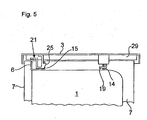
- the laid table top 3 is then pulled forward in the mounting direction I, whereby the two rear hooks 19 are guided through the recesses 15 of the rear connecting flange 14 until end stops 33 of the hooks 19 abut against the connecting flange 14.
- the still inclined table top 3 is brought in a pivoting movement II in latching engagement with the front frame 6.
- the geometry of the suspension hook 19 is designed so that the table top 3 can only be pivoted in certain positions. As a result, damage to the housing side walls 7 is avoided by the table top edge.
- positioning mandrels 37 are provided in addition to the front latching elements 21 as front-side positioning points. These protrude in correct position positioning in corresponding fishing holes 39 which are provided adjacent to the recesses 15 in the upper frame strip of the front frame 6.
- the angled end 26 of the second U-leg 24 of the locking element 21 to the underside of the table top 3 is to raise.
- the front side edge 27 to engage under and then push up the angled end 26.
- the mutually opposing clamping forces F K are introduced via the attachment points 17 of the table top 3 in the treatment tank 1.
- the attachment points 17 are offset from the narrow edge sides 5 in the direction of action y of the clamping forces F K by an offset a to the inside.
- the distance b between the attachment points 17 is reduced such that the compressive stress generated by the clamping forces F K in the table top 3 is smaller than a critical compressive stress, in which a buckling of the table top 3 takes place.
- the table top 3 bends when applying the clamping forces F K only so far until a mounting game between the locking elements 21 and the Einitatihaken 19 and the recesses 15 is eliminated. After the removal of the mounting game and the front frame 6 and the treatment container 1 is included in the force path of the clamping forces.
Landscapes
- Engineering & Computer Science (AREA)
- General Engineering & Computer Science (AREA)
- Textile Engineering (AREA)
- Mechanical Engineering (AREA)
- Washing And Drying Of Tableware (AREA)
- Table Devices Or Equipment (AREA)
- Hooks, Suction Cups, And Attachment By Adhesive Means (AREA)
- Food-Manufacturing Devices (AREA)
Description
- Die Erfindung betrifft ein Haushaltsstandgerät, insbesondere eine Geschirrspülmaschine, mit einem Behandlungsbehälter sowie einem Kraftaufnehmerelement, welches von außen auf das Haushaltsstandgerät ausgeübte Klammerkräfte in das Haushaltsstandgerät einleitet, auf dem oberseitig eine Tischplatte angeordnet ist, wobei die Tischplatte und/oder die Befestigung der Tischplatte an dem Haushaltsstandgerät das Kraftaufnehmerelement bildend ausgeführt sind, in das die Klammerkräfte einleitbar sind, und wobei die Tischplatte über beabstandete Befestigungspunkte auf dem Haushaltsstandgerät befestigt ist.
- Der Transport beziehungsweise das Stapeln von Haushaltsstandgeräten wie zum Beispiel Geschirrspülmaschinen, Waschmaschinen, Wäschetrocknern, Öfen oder Kühlschränken kann werksseitig mittels eines sogenannten Klammerstaplers erfolgen. Dieser bringt von außen Klammerkräfte auf gegenüberliegende Gehäuseseiten des Haushaltsstandgeräts auf.
- Um hierbei Transportschäden, wie etwa Deformationen, an den Gehäuseseiten beispielsweise einer Geschirrspülmaschine zu vermeiden, sind in einer Geschirrspülmaschine zwischen den Gehäuseseitenwänden und gegenüberliegenden Behälterwänden des Behandlungsbehälters Kraftaufnehmerelemente vorgesehen, über die die Klammerkräfte in den Behandlungsbehälter eingeleitet werden. Eine gegebenenfalls vorgesehene oberseitige Tischplatte befindet sich demgegenüber außerhalb des Kraftpfads der eingeleiteten Klammerkräfte.
- Die Druckschrift
WO 2005/124008 A1 offenbart eine Waschmaschine mit einem Gehäusedeckel. Der Gehäusedeckel ist in den vier Eckbereichen über Befestigungspunkte mit den vier Gehäusewänden der Waschmaschine verbunden. Zudem ist auf der Unterseite des Gehäusedeckels ein Träger vorgesehen, der über mehrere Abstützpunkte an dem Gehäusedeckel befestigt ist. Der Träger ist mit seinen Enden an gegenüberliegenden seitlichen Gehäusewänden der Waschmaschine befestigt. - Die Druckschrift
DE 198 43 228 C1 offenbart ist ein Haushaltsgerät mit einem Gehäusedeckel. Bei dem als Waschmaschine ausgeführten Haushaltsgerät weist der Gehäusedeckel einen Außenrahmen auf, in den eine Platte eingelegt ist. Der Außenrahmen des Gehäusedeckels ist in den vier Eckbereichen über Befestigungsmittel mit einem Gehäuserahmenrand des Haushaltsgeräts, welcher aus den vier Seitenwänden des Haushaltsgeräts gebildet ist, verbunden. - Die Druckschrift
US 2005/0178163 A1 offenbart eine Waschmaschine mit einem Gehäusedeckel, wobei der Gehäusedeckel eine Platte mit einem umlaufenden Außenrahmen aufweist. Der Außenrahmen dient zur Versteifung der Platte und ist in vier Eckbereichen mit dem Gehäuse der Waschmaschine, welcher aus den vier Seitenwänden des Haushaltsgeräts gebildet ist, verbunden. - Die Aufgabe der Erfindung besteht darin, ein Haushaltsstandgerät bereitzustellen, das mit geringem Bauteilaufwand den Klammerkräften beim Transportieren oder Stapeln standhält.
- Die Aufgabe ist durch die Merkmale des Patentanspruchs 1 gelöst. Bevorzugte Weiterbildungen der Erfindung sind in den abhängigen Patentansprüchen offenbart.
- Gemäß dem kennzeichnenden Teil des Patentanspruchs 1 ist der Abstand der Befestigungspunkte in einer Wirkrichtung der Klammerkräfte derart eingestellt, dass die durch die Klammerkräfte erzeugte Druckspannung in der Tischplatte kleiner ist als eine kritische Druckspannung, bei der ein Knicken der Tischplatte in einem unelastischen Bereich erfolgt und dass die Tischplatte mit vorderen Befestigungspunkten an einem frontseitigen Rahmen des Behandlungsbehälters und mit hinteren Befestigungspunkten an einem zweiten Abschnitt des Behandlungsbehälters angeordnet ist.
- Bei der Beaufschlagung des Haushaltsstandgeräts mit Klammerkräften befindet sich daher die Tischplatte in dem Kraftpfad der Klammerkräfte. Zusätzliche Kraftaufnehmerelemente zur Durchleitung der Klammerkräfte können daher im Sinne einer Bauteilreduzierung weggelassen werden.
- Die erfindungsgemäße Tischplatte ist im Hinblick auf die Beaufschlagung mit den Klammerkräften ausgelegt. Für eine besonders einfache Auslegung der Tischplatte im Hinblick auf die Einleitung der Klammerkräfte in das Haushaltsstandgerät sind die Befestigungspunkte der Tischplatte zur Befestigung an dem Haushaltsstandgerät von Bedeutung.. Eine derartige Auslegung der Befestigungspunkte kann vorteilhaft mittels einer herkömmlichen Tischplatte erfolgen, bei der lediglich der Befestigungspunkt-Abstand eingestellt wird. Eine zusätzliche Anpassung der Tischplatte mit Bezug auf das Plattenmaterial oder die Plattengeometrie ist hier nicht erforderlich.
- Vor diesem Hintergrund kann in einem Verfahren zur Auslegung der Tischplatte zunächst auf der Grundlage der mittels der Klammerkräfte in die Tischplatte eingebrachten Druckspannung eine kritische Knicklänge zwischen den betreffenden Befestigungspunkten ermittelt werden, bei der die Tischplatte ausknickt. Bei einer Auslegung des Befestigungspunkt-Abstands kleiner als die kritische Knicklänge kann somit das Ausknicken bei der eingebrachten Klammerspannung verhindert werden. Bevorzugt sind hierbei die Befestigungspunkte der Tischplatte von deren Seitenrand um ein entsprechendes Versatzmaß nach innen versetzt.
- Auf Grund seiner inneren Formstabilität eignet sich der Behandlungsbehälter des Haushaltsstandgeräts zur Einleitung der seitlichen Klammerkräfte.
- Um einen entsprechenden Kräftepfad von der Tischplatte in den Behandlungsbehälter bereitzustellen, kann die Tischplatte mit ihren hinteren Befestigungspunkten an einem rückseitigen Verbindungsflansch zwischen einer Deckwand und einer Rückwand des Behandlungsbehälters angeordnet sein.
- Bei einem einfachen Montagevorgang zur Befestigung der Tischplatte auf das Haushaltsstandgerät kann die Tischplatte in einer Schräglage auf das Haushaltsstandgerät gesetzt und entsprechend vorpositioniert werden. Anschließend kann die schräg gestellte Tischplatte in eine horizontale Gebrauchslage auf das Haushaltsstandgerät geschwenkt werden und dort beispielsweise verrasten. Für diesen Montagevorgang kann die Tischplatte als Befestigungspunkte Anlenkelemente, etwa Einhängehaken, aufweisen, mit deren Hilfe die Tischplatte schwenkbar an dem Haushaltsstandgerät anlenkbar ist. Auf der gegenüberliegenden Randseite kann die Tischplatte Rastelemente aufweisen, die nach der Vorpositionierung der Tischplatte durch Schwenkbewegung derselben in Rasteingriff mit dem Haushaltsstandgerät bringbar ist.
- Bevorzugt ist es, wenn die Anlenkelemente zum Vorpositionieren der Tischplatte geräterückseitig an dem Verbindungsflansch des Behandlungsbehälters eingreifen, und die Rastelemente gerätefrontseitig mit dem Frontrahmen des Behandlungsbehälters verrastet werden. Dadurch ist eine einfache Montage der Tischplatte von vorne ermöglicht. Entsprechend kann in der Fertigungslinie die Bereitstellung von Tischplatten von vorne erfolgen und ist keine Sonderbeschickung von hinten erforderlich.
- Für eine lagerichtige Positionierung der Tischplatte können den Rastelementen Positionierdorne zugeordnet sein. Diese können bei der Schwenkbewegung der vormontierten, schräggestellten Tischplatte in deren Gebrauchslage in eine korrespondierende Positionieröffnung formschlüssig einragen. Bevorzugt sind die Positionierdorne in dem vorderen Bereich des Haushaltsstandgeräts angeordnet, damit die Tischplatte zur frontseitigen Bedienblende ausgerichtet werden kann.
- Bei der oben erwähnten Vormontage der Tischplatte, die in Schräglage auf die Oberseite des Haushaltsstandgeräts gesetzt wird, sind Beschädigungen der Gehäuseseitenwände beziehungsweise der Kanten der Tischplatte zu vermeiden. Hierzu können seitliche Auflageleisten an der Unterseite der Tischplatte vorgesehen werden. Somit liegt die Tischplatte bei der Vormontage nicht unmittelbar, sondern über die seitlichen Auflageleisten auf oberen Gehäusekanten des Haushaltsstandgeräts.
- Außerdem kann jedes der Rastelemente einen Betätigungshebel aufweisen, bei dessen Betätigung das Rastelement werkzeugfrei in eine Entriegelungsstellung bringbar ist. Für eine einfach manuelle Betätigung ist es von Vorteil, wenn der Betätigungshebel des Rastelements zu einer Randseite der Tischplatte ragt.
- Die Befestigungselemente der Tischplatte, etwa die Anlenkelemente und/oder die Rastelemente können bevorzugt voneinander separate Bauteile sein. In diesem Fall können in einfacher Weise die Anlenkelemente beziehungsweise die Rastelemente entlang einer oberen Rahmenleiste des Frontrahmens beziehungsweise entlang des rückseitigen Verbindungsflanschs in ihrer Position eingestellt werden, um einen, entsprechend der kritischen Knickspannung der Tischplatte ausgelegten Befestigungspunkt-Abstand zu erhalten.
- Die Anlenkelemente beziehungsweise Rastelemente können bevorzugt insgesamt ausreichend nachgiebig gestaltet sein, um Maßtoleranzen ausgleichen zu können. Derart "weich" gestaltete Befestigungspunkte können darüber hinaus beim Umfallen des Haushaltsstandgeräts eingeleitete Aufprallkräfte abbauen.
- Ferner kann vorzugsweise vorgesehen sein, dass die Tischplatte Versteifungsmittel aufweist.
- Dabei ist vorzugsweise vorgesehen, dass die Versteifungsmittel wenigstens zwischen zwei Befestigungspunkten angeordnet sind, über die die Tischplatte an dem Haushaltsstandgerät befestigt ist. Das heißt, die Versteifungsmittel sind lediglich in Bereichen hoher mechanischer Belastung angeordnet.
- Schließlich ist vorzugsweise vorgesehen, dass das Versteifungsmittel in dem Inneren der Tischplatte oder an einer Außenfläche der Tischplatte angeordnet ist. Das heißt, dass Versteifungsmittel kann in einer Nut der Tischplatte eingesetzt sein, die beispielsweise an der Unterseite der Tischplatte angeordnet ist oder alternativ kann die Tischplatte auf die Unterseite der Tischplatte aufgesetzt und mit ihr verbunden sein. Dabei kann das Versteifungsmittel beispielsweise aus Metall oder Kunststoff gefertigt sein und beispielsweise eine im Wesentlichen stabförmige oder rechteckförmige Gestalt aufweisen.
- Nachfolgend ist ein Ausführungsbeispiel der Erfindung anhand der beigefügten Figuren beschrieben.
- Es zeigen:
- Fig. 1
- in einer perspektivischen Teilansicht von vorne eine teilmontierte Geschirrspülmaschine mit einer auf dem Behandlungsbehälter montierten Tischplatte;
- Fig. 2
- in einer der
Fig. 1 entsprechenden Ansicht den freigelegten Behandlungsbehälter; - Fig. 3
- in einer perspektivischen Ansicht die Unterseite der Tischplatte;
- Fig. 4 und Fig. 5
- einen Montagevorgang zur Befestigung der Tischplatte; und
- Fig. 6
- in einer der
Fig. 4 und5 entsprechenden Ansicht einen Positionierdorn der Tischplatte. - Im vorliegenden Ausführungsbeispiel ist für ein Haushaltsstandgerät in der
Fig. 1 eine teilmontierte Geschirrspülmaschine mit einem frontseitig offenen Behandlungsbehälter 1 sowie einer darauf angeordneten Tischplatte 3 gezeigt. Die Tischplatte 3 umgreift mit ihren beiden schmalen Randseiten 5 die Oberkanten der Gehäuseseitenwände 7. Die Beschickungsöffnung des Behandlungsbehälters 1 ist in bekannter Weise von einem frontseitigen Rahmen 9 begrenzt, der in seinem Querschnitt mit einem nach außen offenen U-Profil versehen ist. - Der Behandlungsbehälter 1 kann gemäß der
Fig. 2 beispielhaft einen kastenförmigen, ringartig geschlossenen Blechmantel mit rechteckigem Querschnitt aufweisen, der eine Deckwand 10, die beiden Seitenwände 11 sowie eine nicht gezeigte Bodenwand des Behandlungsbehälters 1 bildet. Die beiden Gehäuseseitenwände 7 sind aus Gründen der Übersichtlichkeit lediglich gestrichelt angedeutet. - An seiner Rückseite ist der kastenförmige Blechmantel durch eine in etwa wannenförmig ausgebildete Rückwand 13 geschlossen. Die Rückwand 13 weist davon abgewinkelte Seitenränder mit einem Verbindungsflansch 14 auf, der in bekannter Weise mit entsprechenden Verbindungsflanschen 14 an dem Blechmantel verschweißt ist.
- Wie aus der
Fig. 2 weiter hervorgeht, sind an dem innenliegenden Schenkel des U-profilförmigen Frontrahmens 6 sowie an dem Verbindungsflansch 14 der Deckwand 10 Ausnehmungen 15 vorgesehen, in die die Tischplatte 3 eingehängt beziehungsweise verrastet werden kann. Hierzu weist die Tischplatte 3 gemäß derFig. 3 an ihrer Unterseite Befestigungspunkte 17 auf. Die beiden geräterückseitigen Befestigungspunkte 17 sind hier beispielhaft Einhängehaken 19, die über entsprechende Sockel an der Tischplatte 3 befestigt sind. Die beiden vorderen Befestigungspunkte 17 der Tischplatte 3 weisen demgegenüber Rastelemente 21 auf, deren Rastvorsprünge 25 den beiden hinteren Einhängehaken 19 zugewandt sind. - Jedes der Rastelemente 21 ist als ein U-förmiges Kunststoffprofilteil mit zwei U-Schenkeln 23, 24 ausgebildet. Der erste U-Schenkel 23 des Rastelements 21 ist an seinem abgewinkelten Ende fest mit der Unterseite der Tischplatte 3 in Verbindung. An seiner, dem Einhängehaken 19 zugewandten Seite weist der U-Schenkel 23 den Rastvorsprung 25 auf und ist über einen Steg 26' mit dem zweiten U-Schenkel 24 in Verbindung. Der zweite U-Schenkel 24 ist mit seinem abgewinkelten Ende 26 frei bewegbar gegenüber der Tischplatte 3 angeordnet. Das abgewinkelte Ende 26 ragt in Richtung des vorderen Seitenrands 27 der Tischplatte 3. Wie später beschrieben wird, kann in Gebrauchslage der Tischplatte 3 der vordere Seitenrand 27 der Tischplatte 3 untergriffen und durch Betätigung des abgewinkelten Endes 26 das Rastelement 21 aus seiner Verriegelungsposition gebracht werden.
- In den
Fig. 4 und5 ist der Montagevorgang zur Befestigung der Tischplatte 3 auf der Geschirrspülmaschine gezeigt. Demzufolge wird die Tischplatte 3 in Schrägstellung mit ihrer rückwärtigen Seite auf obere Kanten der Gehäuseseitenwände 7 aufgelegt. Um hierbei eine Beschädigung der Gehäuseseitenwände 7 während des Montagevorgangs zu vermeiden, sind an der Unterseite der Tischplatte 3 seitliche Auflagerippen 29 vorgesehen. In der inFig. 4 gezeigten Schräglage liegt daher die Tischplatte 3 nicht unmittelbar auf den Gehäuseseitenwänden 7 auf, sondern unter Zwischenschaltung der beiden Auflagerippen 29. Die Auflagerippen 29 verhindern somit eine Beschädigung der Gehäuseseitenwände 7 während der Tischmontage. Außerdem ermöglichen die Auflagerippen 29 eine Auflage der Tischplatte über einen größeren Bereich, so dass die Tischplatten-Montage auch für ungeübte Montierer durchführbar ist. Die aufgelegte Tischplatte 3 wird dann in der Montagerichtung I nach vorne gezogen, wodurch die beiden hinteren Einhängehaken 19 durch die Ausnehmungen 15 des hinteren Verbindungsflanschs 14 geführt werden, bis Endanschläge 33 der Einhängehaken 19 an den Verbindungsflansch 14 stoßen. - In dem Endanschlag wird die noch schräg gestellte Tischplatte 3 in einer Schwenkbewegung II in Rasteingriff mit dem Frontrahmen 6 gebracht. Dabei ist die Geometrie des Einhängehakens 19 so ausgebildet, dass die Tischplatte 3 nur bei bestimmten Positionen eingeschwenkt werden kann. Hierdurch wird eine Beschädigung der Gehäuseseitenwände 7 durch den Tischplattenrand vermieden.
- Der Rasteingriff der Tischplatte 3 ist in der
Fig. 5 gezeigt. Daraus geht hervor, dass der Rastvorsprung 25 des Rastelements 21 die Ausnehmung 15 in dem Frontrahmen 6 hintergreift. - Damit die Tischplatte 3 zur frontseitigen Bedienblende der Geschirrspülmaschine ausgerichtet ist, sind zusätzlich zu den vorderen Rastelementen 21 als frontseitige Positionierungspunkte Positionierdorne 37 vorgesehen. Diese ragen bei lagerichtiger Positionierung in korrespondierende Fanglöcher 39 ein, die benachbart zu den Ausnehmungen 15 in der oberen Rahmenleiste des Frontrahmens 6 vorgesehen sind.
- Für eine einfache Demontage der Tischplatte 3 ist das abgewinkelte Ende 26 des zweiten U-Schenkels 24 des Rastelements 21 zur Unterseite der Tischplatte 3 anzuheben. Hierzu ist der vordere Seitenrand 27 zu untergreifen und anschließend das abgewinkelte Ende 26 hochzudrücken.
- Für den Fall, dass die fertig montierte Geschirrspülmaschine werksseitig mittels eines Klammerstaplers transportiert und/oder gestapelt wird, werden in der Geräte-Seitenrichtung y Klammerkräfte FK auf die schmalen Randseiten 5 der Tischplatte 3 aufgebracht.
- Die einander entgegen gerichteten Klammerkräfte FK werden über die Befestigungspunkte 17 der Tischplatte 3 in den Behandlungsbehälter 1 eingebracht. Um ein Ausknicken der Tischplatte 3 wegen Überlasten zu vermeiden, sind die Befestigungspunkte 17 von deren schmalen Randseiten 5 in der Wirkrichtung y der Klammerkräfte FK um ein Versatzmaß a nach innen versetzt. Dadurch ist entsprechend der Abstand b zwischen den Befestigungspunkten 17 derart reduziert, dass die durch die Klammerkräfte FK erzeugte Druckspannung in der Tischplatte 3 kleiner ist als eine kritische Druckspannung, bei der ein Ausknicken der Tischplatte 3 erfolgt. Durch eine solche Verkürzung des Abstands, das heißt der Knicklänge, zwischen den Befestigungspunkten 17 wird die Steifigkeit der Tischplatte 3 erhöht. Dadurch erheblich größere Klammerkräfte FK aufgenommen werden.
- Erfindungsgemäß biegt sich die Tischplatte 3 beim Aufbringen der Klammerkräfte FK nur soweit durch, bis ein Montagespiel zwischen den Rastelementen 21 und den Einhängehaken 19 sowie den Ausnehmungen 15 beseitigt ist. Nach der Beseitigung des Montagespiels wird auch der Frontrahmen 6 und der Behandlungsbehälter 1 in den Kraftpfad der Klammerkräfte einbezogen.
-
- 1
- Behandlungsbehälter
- 3
- Tischplatte
- 5
- Randseite
- 7
- Gehäuseseitenwand
- 9
- Frontseitiger Rahmen
- 10
- Deckwand
- 11
- Seitenwand
- 13
- Rückwand
- 14
- Verbindungsflansch
- 15
- Ausnehmung
- 17
- Befestigungspunkt
- 19
- Einhängehaken
- 21
- Rastelement
- 23
- U-Schenkel
- 24
- U-Schenkel
- 25
- Rastvorsprung
- 26
- Abgewinkeltes Ende
- 26'
- Steg
- 27
- Vorderer Seitenrand
- 29
- Auflagerippe
- 33
- Endanschlag
- 37
- Positionierdorn
- 39
- Fangloch
- a
- Versatzmaß
- b
- Abstand
- FK
- Klammerkraft
- I
- Montagerichtung
- II
- Montagerichtung
- y
- Geräte-Seitenrichtung; Wirkrichtung
Claims (16)
- Haushaltsstandgerät, insbesondere Geschirrspülmaschine, mit einem Behandlungsbehälter (1) sowie einem Kraftaufnehmerelement, welches von außen auf das Haushaltsstandgerät ausgeübte Klammerkräfte (FK) in das Haushaltsstandgerät einleitet, auf dem oberseitig eine Tischplatte (3) angeordnet ist, wobei die Tischplatte (3) und/oder die Befestigung der Tischplatte (3) an dem Haushaltsstandgerät das Kraftaufnehmerelement bildend ausgeführt sind, in das die Klammerkräfte (FK) einleitbar sind, und wobei die Tischplatte (3) über beabstandete Befestigungspunkte (17) auf dem Haushaltsstandgerät befestigt ist, dadurch gekennzeichnet, dass die Tischplatte (3) mit vorderen Befestigungspunkten (17) an einem frontseitigen Rahmen (9) des Behandlungsbehälters (1) und mit hinteren Befestigungspunkten (17) an einem zweiten Abschnitt des Behandlungsbehälters (1) angeordnet ist, und dass der Abstand (b) der Befestigungspunkte (17) auf dem Haushaltsstandgerät in einer Wirkrichtung (y) der Klammerkräfte (FK) derart eingestellt ist, dass die durch die Klammerkräfte (FK) erzeugte Druckspannung in der Tischplatte (3) kleiner ist als eine kritische Druckspannung, bei der ein Knicken der Tischplatte (3) in einem unelastischen Bereich erfolgt.
- Haushaltsstandgerät nach Anspruch 1, dadurch gekennzeichnet, dass die Tischplatte (3) mit hinteren Befestigungspunkten (17) an einem rückseitigen Verbindungsflansch (14) zwischen einer Deckwand (9) und einer Rückwand (13) des Behandlungsbehälters (1) angeordnet ist.
- Haushaltsstandgerät nach Anspruch 2, dadurch gekennzeichnet, dass die Einstellung des Abstands (b) durch eine Verlagerung der vorderen und/oder der hinteren Befestigungspunkte (17) im Wesentlichen in Wirkrichtung der Klammerkräfte (FK) erfolgt.
- Haushaltsstandgerät nach einem der vorhergehenden Ansprüche, dadurch gekennzeichnet, dass die Befestigungspunkte (17) der Tischplatte (3) von deren Randseiten (5) in Wirkrichtung (y) der Klammerkräfte (FK) um ein Versatzmaß (a) nach innen versetzt sind.
- Haushaltsstandgerät nach einem der vorhergehenden Ansprüche, dadurch gekennzeichnet, dass wenigstens ein Befestigungspunkt (17) zumindest ein Anlenkelement (19) aufweist, mit dem die Tischplatte (3) an dem Haushaltsstandgerät vorpositionierbar ist.
- Haushaltsstandgerät nach Anspruch 5, dadurch gekennzeichnet, dass die Tischplatte (3) zumindest ein Rastelement (21) aufweist, das in Rasteingriff mit dem Haushaltsstandgerät bringbar ist.
- Haushaltsstandgerät nach Anspruch 5 oder 6, dadurch gekennzeichnet, dass das wenigstens eine Anlenkelement (19) an einem ersten Abschnitt des Behandlungsbehälters (1), insbesondere geräterückseitig an dem Verbindungsflansch (14) des Behandlungsbehälters (1) anlenkbar ist.
- Haushaltsstandgerät nach Anspruch 7, dadurch gekennzeichnet, dass das wenigstens eine Rastelement (21) mit einem zweiten Abschnitt des Behandlungsbehälters (1), insbesondere gerätefrontseitig mit dem frontseitigen Rahmen (9) des Behandlungsbehälters (1) in Rasteingriff bringbar ist.
- Haushaltsstandgerät nach Anspruch 6 oder 7, dadurch gekennzeichnet, dass dem Rastelement (21) der Tischplatte (3) zumindest ein Positionierelement (37) zugeordnet ist, das in einer Gebrauchslage der Tischplatte (3) in Formschlussverbindung mit dem Haushaltsstandgerät ist.
- Haushaltsstandgerät nach einem der vorhergehenden Ansprüche, dadurch gekennzeichnet, dass die Tischplatte (3) an ihrer Unterseite seitliche Auflageelemente (29) aufweist, über die die Tischplatte (3) während des Montagevorgangs des Haushaltsstandgeräts aufliegt.
- Haushaltsstandgerät nach einem der Ansprüche 6 bis 10, dadurch gekennzeichnet, dass das Rastelement (21) einen Betätigungshebel (26) aufweist, bei dessen Betätigung das Rastelement (21) in eine Entriegelungsstellung bringbar ist.
- Haushaltsstandgerät nach Anspruch 11, dadurch gekennzeichnet, dass der Betätigungshebel (26) des Rastelements (21) zu einer Randseite (27) der Tischplatte (3) ragt.
- Haushaltsstandgerät nach einem der Ansprüche 5 bis 12, dadurch gekennzeichnet, dass die Anlenkelemente (19) und/oder die Rastelemente (21) voneinander separate Bauteile sind.
- Haushaltsstandgerät nach einem der vorhergehenden Ansprüche, dadurch gekennzeichnet, dass die Tischplatte (3) Versteifungsmittel aufweist.
- Haushaltsstandgerät nach Anspruch 14, dadurch gekennzeichnet, dass die Versteifungsmittel wenigstens zwischen zwei Befestigungspunkten (17) angeordnet sind, über die die Tischplatte (3) an dem Haushaltsstandgerät befestigt ist.
- Haushaltsstandgerät nach Anspruch 14 oder 15, dadurch gekennzeichnet, dass das Versteifungsmittel in dem Inneren der Tischplatte (3) oder an einer Außenfläche der Tischplatte (3) angeordnet ist.
Priority Applications (1)
| Application Number | Priority Date | Filing Date | Title |
|---|---|---|---|
| PL09725716T PL2262406T3 (pl) | 2008-03-27 | 2009-03-24 | Wolnostojące urządzenie gospodarstwa domowego |
Applications Claiming Priority (2)
| Application Number | Priority Date | Filing Date | Title |
|---|---|---|---|
| DE102008015944A DE102008015944A1 (de) | 2008-03-27 | 2008-03-27 | Haushaltsstandgerät |
| PCT/EP2009/053429 WO2009118309A1 (de) | 2008-03-27 | 2009-03-24 | Haushaltsstandgerät |
Publications (2)
| Publication Number | Publication Date |
|---|---|
| EP2262406A1 EP2262406A1 (de) | 2010-12-22 |
| EP2262406B1 true EP2262406B1 (de) | 2018-12-05 |
Family
ID=40874670
Family Applications (1)
| Application Number | Title | Priority Date | Filing Date |
|---|---|---|---|
| EP09725716.6A Active EP2262406B1 (de) | 2008-03-27 | 2009-03-24 | Haushaltsstandgerät |
Country Status (5)
| Country | Link |
|---|---|
| EP (1) | EP2262406B1 (de) |
| DE (1) | DE102008015944A1 (de) |
| PL (1) | PL2262406T3 (de) |
| TR (1) | TR201819993T4 (de) |
| WO (1) | WO2009118309A1 (de) |
Families Citing this family (8)
| Publication number | Priority date | Publication date | Assignee | Title |
|---|---|---|---|---|
| WO2012089457A2 (en) | 2010-12-27 | 2012-07-05 | Arcelik Anonim Sirketi | A household appliance comprising a work top |
| EP3152356B1 (de) * | 2014-06-06 | 2018-06-06 | Arçelik Anonim Sirketi | Haushaltsgerät mit einem dämpfungselement |
| EP3261508A1 (de) * | 2015-02-25 | 2018-01-03 | Arçelik Anonim Sirketi | Haushaltsgerät mit verbesserter abdeckungsanordnung |
| DE102015219321A1 (de) * | 2015-10-07 | 2017-04-13 | BSH Hausgeräte GmbH | Abdeckteil für ein Haushaltsgerät, Tür für ein Haushaltsgerät sowie Haushaltsgerät |
| EP3426836B1 (de) * | 2016-03-08 | 2019-11-06 | Arçelik Anonim Sirketi | Waschmaschine oder waschtrockner |
| CN110742567A (zh) * | 2019-10-08 | 2020-02-04 | 珠海格力电器股份有限公司 | 一种连接组件及家用电器 |
| CN113718492A (zh) * | 2021-08-24 | 2021-11-30 | 创维电器股份有限公司 | 一种一体化超薄顶盖及其安装结构 |
| CN121908976A (zh) * | 2023-09-20 | 2026-04-21 | 伊莱克斯电器股份公司 | 配备有支撑基座的洗碗机 |
Family Cites Families (7)
| Publication number | Priority date | Publication date | Assignee | Title |
|---|---|---|---|---|
| ES254414Y (es) * | 1979-12-10 | 1981-10-01 | Maquina lavadora con plano de trabajo regulable en profun- didad | |
| DE4446961C2 (de) * | 1994-12-28 | 1997-03-06 | Bosch Siemens Hausgeraete | Haushaltgerät |
| DE19843228C1 (de) * | 1998-09-22 | 2000-01-27 | Miele & Cie | Befestigungsanordnung für den Gehäusedeckel eines Haushaltgerätes |
| KR101013375B1 (ko) * | 2003-11-10 | 2011-02-14 | 삼성전자주식회사 | 드럼세탁기 |
| KR20050081456A (ko) * | 2004-02-13 | 2005-08-19 | 엘지전자 주식회사 | 드럼 세탁기의 탑 플레이트 |
| EP1759050A1 (de) * | 2004-06-21 | 2007-03-07 | Farel Plastik Elektrik ve Elektronik Imalat Sanayi A.S. | Verbesserungen bei waschmaschinendeckel |
| KR101239766B1 (ko) * | 2005-04-06 | 2013-03-06 | 삼성전자주식회사 | 드럼 세탁기 |
-
2008
- 2008-03-27 DE DE102008015944A patent/DE102008015944A1/de not_active Ceased
-
2009
- 2009-03-24 EP EP09725716.6A patent/EP2262406B1/de active Active
- 2009-03-24 PL PL09725716T patent/PL2262406T3/pl unknown
- 2009-03-24 TR TR2018/19993T patent/TR201819993T4/tr unknown
- 2009-03-24 WO PCT/EP2009/053429 patent/WO2009118309A1/de not_active Ceased
Non-Patent Citations (1)
| Title |
|---|
| None * |
Also Published As
| Publication number | Publication date |
|---|---|
| PL2262406T3 (pl) | 2019-05-31 |
| EP2262406A1 (de) | 2010-12-22 |
| WO2009118309A1 (de) | 2009-10-01 |
| TR201819993T4 (tr) | 2019-02-21 |
| DE102008015944A1 (de) | 2009-10-01 |
Similar Documents
| Publication | Publication Date | Title |
|---|---|---|
| EP0943721B2 (de) | Gehäuse für eine frontbeschickbare Wäschebehandlungsmaschine | |
| WO2009118309A1 (de) | Haushaltsstandgerät | |
| WO2009118316A1 (de) | Teleskopierbare auszugsführung | |
| WO2009068395A1 (de) | Haushaltsgerät, insbesondere geschirrspülmaschine | |
| AT518076B1 (de) | Schubladenseitenwand | |
| EP2465404B1 (de) | Geschirrspülmaschine, insbesondere Haushalts-Geschirrspülmaschine | |
| DE102010063448A1 (de) | Geschirrspülmaschine | |
| DE102007052072A1 (de) | Haushaltsgerät | |
| WO2018224322A1 (de) | Spülbehälter und haushaltsgeschirrspülmaschine | |
| EP2484264B1 (de) | Geschirrspülmaschine, insbesondere haushalts-geschirrspülmaschine | |
| WO2015124433A1 (de) | Haushaltskältegerät mit einem innenraum, in dem ein träger verschiebbar angeordnet ist, auf dem ein behälter bewegungsgekoppelt angeordnet ist | |
| EP2446798B1 (de) | Geschirrspülmaschine mit einer verbesserten Kederanordnung | |
| EP3290603A1 (de) | Entwässerungsrinne | |
| EP4286749B1 (de) | Schnellbefestigungssystem für einen teleskopauszug | |
| DE102008032266B4 (de) | Haushaltsgerät, insbesondere Geschirrspülmaschine | |
| EP2311347B1 (de) | Verschlusselement zum Verschließen eines Spaltes zwischen Einbaugerät und Möbelumbau | |
| DE102010039472A1 (de) | Geschirrspülmaschine, insbesondere Haushalts-Geschirrspülmaschine | |
| EP3666121B1 (de) | Schubladenfront-verbindungsvorrichtung und schublade | |
| WO2022228907A1 (de) | Haushaltskältegerät mit spezifischer maschinenraum-rückwand, sowie montageverfahren | |
| EP3629874B1 (de) | Spülbehälter, haushaltsgeschirrspülmaschine und verfahren | |
| EP1228719B1 (de) | Schubkasten mit lösbarer Frontblende | |
| DE102011077494B4 (de) | Haushaltsgerät mit einem Rahmen und Kraftaufnahmeelementen | |
| EP3082512B1 (de) | Möbelschublade und schubladenwandelement für eine schublade | |
| EP3835663B1 (de) | Kombinationsgerät umfassend ein kochfeld und eine dunstabzugsvorrichtung | |
| EP2465402A2 (de) | Geschirrspülmaschine |
Legal Events
| Date | Code | Title | Description |
|---|---|---|---|
| PUAI | Public reference made under article 153(3) epc to a published international application that has entered the european phase |
Free format text: ORIGINAL CODE: 0009012 |
|
| 17P | Request for examination filed |
Effective date: 20101027 |
|
| AK | Designated contracting states |
Kind code of ref document: A1 Designated state(s): AT BE BG CH CY CZ DE DK EE ES FI FR GB GR HR HU IE IS IT LI LT LU LV MC MK MT NL NO PL PT RO SE SI SK TR |
|
| AX | Request for extension of the european patent |
Extension state: AL BA RS |
|
| DAX | Request for extension of the european patent (deleted) | ||
| RAP1 | Party data changed (applicant data changed or rights of an application transferred) |
Owner name: BSH HAUSGERAETE GMBH |
|
| 17Q | First examination report despatched |
Effective date: 20151022 |
|
| GRAP | Despatch of communication of intention to grant a patent |
Free format text: ORIGINAL CODE: EPIDOSNIGR1 |
|
| STAA | Information on the status of an ep patent application or granted ep patent |
Free format text: STATUS: GRANT OF PATENT IS INTENDED |
|
| RIC1 | Information provided on ipc code assigned before grant |
Ipc: D06F 39/00 20060101ALI20180627BHEP Ipc: A47B 77/02 20060101ALI20180627BHEP Ipc: F16B 12/26 20060101ALI20180627BHEP Ipc: A47L 15/42 20060101AFI20180627BHEP |
|
| INTG | Intention to grant announced |
Effective date: 20180720 |
|
| GRAS | Grant fee paid |
Free format text: ORIGINAL CODE: EPIDOSNIGR3 |
|
| GRAA | (expected) grant |
Free format text: ORIGINAL CODE: 0009210 |
|
| GRAA | (expected) grant |
Free format text: ORIGINAL CODE: 0009210 |
|
| STAA | Information on the status of an ep patent application or granted ep patent |
Free format text: STATUS: THE PATENT HAS BEEN GRANTED |
|
| AK | Designated contracting states |
Kind code of ref document: B1 Designated state(s): AT BE BG CH CY CZ DE DK EE ES FI FR GB GR HR HU IE IS IT LI LT LU LV MC MK MT NL NO PL PT RO SE SI SK TR |
|
| REG | Reference to a national code |
Ref country code: GB Ref legal event code: FG4D Free format text: NOT ENGLISH |
|
| REG | Reference to a national code |
Ref country code: CH Ref legal event code: EP |
|
| REG | Reference to a national code |
Ref country code: AT Ref legal event code: REF Ref document number: 1072004 Country of ref document: AT Kind code of ref document: T Effective date: 20181215 |
|
| REG | Reference to a national code |
Ref country code: IE Ref legal event code: FG4D Free format text: LANGUAGE OF EP DOCUMENT: GERMAN |
|
| REG | Reference to a national code |
Ref country code: DE Ref legal event code: R096 Ref document number: 502009015490 Country of ref document: DE |
|
| REG | Reference to a national code |
Ref country code: NL Ref legal event code: MP Effective date: 20181205 |
|
| REG | Reference to a national code |
Ref country code: LT Ref legal event code: MG4D |
|
| PG25 | Lapsed in a contracting state [announced via postgrant information from national office to epo] |
Ref country code: FI Free format text: LAPSE BECAUSE OF FAILURE TO SUBMIT A TRANSLATION OF THE DESCRIPTION OR TO PAY THE FEE WITHIN THE PRESCRIBED TIME-LIMIT Effective date: 20181205 Ref country code: NO Free format text: LAPSE BECAUSE OF FAILURE TO SUBMIT A TRANSLATION OF THE DESCRIPTION OR TO PAY THE FEE WITHIN THE PRESCRIBED TIME-LIMIT Effective date: 20190305 Ref country code: LV Free format text: LAPSE BECAUSE OF FAILURE TO SUBMIT A TRANSLATION OF THE DESCRIPTION OR TO PAY THE FEE WITHIN THE PRESCRIBED TIME-LIMIT Effective date: 20181205 Ref country code: ES Free format text: LAPSE BECAUSE OF FAILURE TO SUBMIT A TRANSLATION OF THE DESCRIPTION OR TO PAY THE FEE WITHIN THE PRESCRIBED TIME-LIMIT Effective date: 20181205 Ref country code: LT Free format text: LAPSE BECAUSE OF FAILURE TO SUBMIT A TRANSLATION OF THE DESCRIPTION OR TO PAY THE FEE WITHIN THE PRESCRIBED TIME-LIMIT Effective date: 20181205 Ref country code: BG Free format text: LAPSE BECAUSE OF FAILURE TO SUBMIT A TRANSLATION OF THE DESCRIPTION OR TO PAY THE FEE WITHIN THE PRESCRIBED TIME-LIMIT Effective date: 20190305 Ref country code: HR Free format text: LAPSE BECAUSE OF FAILURE TO SUBMIT A TRANSLATION OF THE DESCRIPTION OR TO PAY THE FEE WITHIN THE PRESCRIBED TIME-LIMIT Effective date: 20181205 |
|
| PG25 | Lapsed in a contracting state [announced via postgrant information from national office to epo] |
Ref country code: SE Free format text: LAPSE BECAUSE OF FAILURE TO SUBMIT A TRANSLATION OF THE DESCRIPTION OR TO PAY THE FEE WITHIN THE PRESCRIBED TIME-LIMIT Effective date: 20181205 Ref country code: GR Free format text: LAPSE BECAUSE OF FAILURE TO SUBMIT A TRANSLATION OF THE DESCRIPTION OR TO PAY THE FEE WITHIN THE PRESCRIBED TIME-LIMIT Effective date: 20190306 |
|
| PG25 | Lapsed in a contracting state [announced via postgrant information from national office to epo] |
Ref country code: NL Free format text: LAPSE BECAUSE OF FAILURE TO SUBMIT A TRANSLATION OF THE DESCRIPTION OR TO PAY THE FEE WITHIN THE PRESCRIBED TIME-LIMIT Effective date: 20181205 |
|
| PG25 | Lapsed in a contracting state [announced via postgrant information from national office to epo] |
Ref country code: CZ Free format text: LAPSE BECAUSE OF FAILURE TO SUBMIT A TRANSLATION OF THE DESCRIPTION OR TO PAY THE FEE WITHIN THE PRESCRIBED TIME-LIMIT Effective date: 20181205 Ref country code: IT Free format text: LAPSE BECAUSE OF FAILURE TO SUBMIT A TRANSLATION OF THE DESCRIPTION OR TO PAY THE FEE WITHIN THE PRESCRIBED TIME-LIMIT Effective date: 20181205 Ref country code: PT Free format text: LAPSE BECAUSE OF FAILURE TO SUBMIT A TRANSLATION OF THE DESCRIPTION OR TO PAY THE FEE WITHIN THE PRESCRIBED TIME-LIMIT Effective date: 20190405 |
|
| PG25 | Lapsed in a contracting state [announced via postgrant information from national office to epo] |
Ref country code: EE Free format text: LAPSE BECAUSE OF FAILURE TO SUBMIT A TRANSLATION OF THE DESCRIPTION OR TO PAY THE FEE WITHIN THE PRESCRIBED TIME-LIMIT Effective date: 20181205 Ref country code: IS Free format text: LAPSE BECAUSE OF FAILURE TO SUBMIT A TRANSLATION OF THE DESCRIPTION OR TO PAY THE FEE WITHIN THE PRESCRIBED TIME-LIMIT Effective date: 20190405 Ref country code: RO Free format text: LAPSE BECAUSE OF FAILURE TO SUBMIT A TRANSLATION OF THE DESCRIPTION OR TO PAY THE FEE WITHIN THE PRESCRIBED TIME-LIMIT Effective date: 20181205 Ref country code: SK Free format text: LAPSE BECAUSE OF FAILURE TO SUBMIT A TRANSLATION OF THE DESCRIPTION OR TO PAY THE FEE WITHIN THE PRESCRIBED TIME-LIMIT Effective date: 20181205 |
|
| REG | Reference to a national code |
Ref country code: DE Ref legal event code: R097 Ref document number: 502009015490 Country of ref document: DE |
|
| PLBE | No opposition filed within time limit |
Free format text: ORIGINAL CODE: 0009261 |
|
| STAA | Information on the status of an ep patent application or granted ep patent |
Free format text: STATUS: NO OPPOSITION FILED WITHIN TIME LIMIT |
|
| PG25 | Lapsed in a contracting state [announced via postgrant information from national office to epo] |
Ref country code: DK Free format text: LAPSE BECAUSE OF FAILURE TO SUBMIT A TRANSLATION OF THE DESCRIPTION OR TO PAY THE FEE WITHIN THE PRESCRIBED TIME-LIMIT Effective date: 20181205 Ref country code: MC Free format text: LAPSE BECAUSE OF FAILURE TO SUBMIT A TRANSLATION OF THE DESCRIPTION OR TO PAY THE FEE WITHIN THE PRESCRIBED TIME-LIMIT Effective date: 20181205 Ref country code: SI Free format text: LAPSE BECAUSE OF FAILURE TO SUBMIT A TRANSLATION OF THE DESCRIPTION OR TO PAY THE FEE WITHIN THE PRESCRIBED TIME-LIMIT Effective date: 20181205 |
|
| REG | Reference to a national code |
Ref country code: CH Ref legal event code: PL |
|
| 26N | No opposition filed |
Effective date: 20190906 |
|
| GBPC | Gb: european patent ceased through non-payment of renewal fee |
Effective date: 20190324 |
|
| PG25 | Lapsed in a contracting state [announced via postgrant information from national office to epo] |
Ref country code: LU Free format text: LAPSE BECAUSE OF NON-PAYMENT OF DUE FEES Effective date: 20190324 |
|
| REG | Reference to a national code |
Ref country code: BE Ref legal event code: MM Effective date: 20190331 |
|
| PG25 | Lapsed in a contracting state [announced via postgrant information from national office to epo] |
Ref country code: GB Free format text: LAPSE BECAUSE OF NON-PAYMENT OF DUE FEES Effective date: 20190324 Ref country code: IE Free format text: LAPSE BECAUSE OF NON-PAYMENT OF DUE FEES Effective date: 20190324 Ref country code: CH Free format text: LAPSE BECAUSE OF NON-PAYMENT OF DUE FEES Effective date: 20190331 Ref country code: LI Free format text: LAPSE BECAUSE OF NON-PAYMENT OF DUE FEES Effective date: 20190331 |
|
| PG25 | Lapsed in a contracting state [announced via postgrant information from national office to epo] |
Ref country code: BE Free format text: LAPSE BECAUSE OF NON-PAYMENT OF DUE FEES Effective date: 20190331 Ref country code: FR Free format text: LAPSE BECAUSE OF NON-PAYMENT OF DUE FEES Effective date: 20190331 |
|
| PG25 | Lapsed in a contracting state [announced via postgrant information from national office to epo] |
Ref country code: MT Free format text: LAPSE BECAUSE OF FAILURE TO SUBMIT A TRANSLATION OF THE DESCRIPTION OR TO PAY THE FEE WITHIN THE PRESCRIBED TIME-LIMIT Effective date: 20181205 |
|
| REG | Reference to a national code |
Ref country code: AT Ref legal event code: MM01 Ref document number: 1072004 Country of ref document: AT Kind code of ref document: T Effective date: 20190324 |
|
| PG25 | Lapsed in a contracting state [announced via postgrant information from national office to epo] |
Ref country code: AT Free format text: LAPSE BECAUSE OF NON-PAYMENT OF DUE FEES Effective date: 20190324 |
|
| PG25 | Lapsed in a contracting state [announced via postgrant information from national office to epo] |
Ref country code: CY Free format text: LAPSE BECAUSE OF FAILURE TO SUBMIT A TRANSLATION OF THE DESCRIPTION OR TO PAY THE FEE WITHIN THE PRESCRIBED TIME-LIMIT Effective date: 20181205 |
|
| PG25 | Lapsed in a contracting state [announced via postgrant information from national office to epo] |
Ref country code: HU Free format text: LAPSE BECAUSE OF FAILURE TO SUBMIT A TRANSLATION OF THE DESCRIPTION OR TO PAY THE FEE WITHIN THE PRESCRIBED TIME-LIMIT; INVALID AB INITIO Effective date: 20090324 |
|
| PG25 | Lapsed in a contracting state [announced via postgrant information from national office to epo] |
Ref country code: MK Free format text: LAPSE BECAUSE OF FAILURE TO SUBMIT A TRANSLATION OF THE DESCRIPTION OR TO PAY THE FEE WITHIN THE PRESCRIBED TIME-LIMIT Effective date: 20181205 |
|
| PGFP | Annual fee paid to national office [announced via postgrant information from national office to epo] |
Ref country code: DE Payment date: 20260331 Year of fee payment: 18 |
|
| PGFP | Annual fee paid to national office [announced via postgrant information from national office to epo] |
Ref country code: TR Payment date: 20260317 Year of fee payment: 18 |
|
| PGFP | Annual fee paid to national office [announced via postgrant information from national office to epo] |
Ref country code: PL Payment date: 20260313 Year of fee payment: 18 |