EP2261603A1 - Wrong-way travel warning device and wrong-way travel warning method - Google Patents
Wrong-way travel warning device and wrong-way travel warning method Download PDFInfo
- Publication number
- EP2261603A1 EP2261603A1 EP09729667A EP09729667A EP2261603A1 EP 2261603 A1 EP2261603 A1 EP 2261603A1 EP 09729667 A EP09729667 A EP 09729667A EP 09729667 A EP09729667 A EP 09729667A EP 2261603 A1 EP2261603 A1 EP 2261603A1
- Authority
- EP
- European Patent Office
- Prior art keywords
- wrong
- way
- vehicle
- travel
- vehicle speed
- Prior art date
- Legal status (The legal status is an assumption and is not a legal conclusion. Google has not performed a legal analysis and makes no representation as to the accuracy of the status listed.)
- Granted
Links
Images






Classifications
-
- G—PHYSICS
- G08—SIGNALLING
- G08G—TRAFFIC CONTROL SYSTEMS
- G08G1/00—Traffic control systems for road vehicles
- G08G1/07—Controlling traffic signals
- G08G1/075—Ramp control
-
- B—PERFORMING OPERATIONS; TRANSPORTING
- B62—LAND VEHICLES FOR TRAVELLING OTHERWISE THAN ON RAILS
- B62D—MOTOR VEHICLES; TRAILERS
- B62D15/00—Steering not otherwise provided for
- B62D15/02—Steering position indicators ; Steering position determination; Steering aids
- B62D15/029—Steering assistants using warnings or proposing actions to the driver without influencing the steering system
-
- G—PHYSICS
- G01—MEASURING; TESTING
- G01C—MEASURING DISTANCES, LEVELS OR BEARINGS; SURVEYING; NAVIGATION; GYROSCOPIC INSTRUMENTS; PHOTOGRAMMETRY OR VIDEOGRAMMETRY
- G01C21/00—Navigation; Navigational instruments not provided for in groups G01C1/00 - G01C19/00
- G01C21/26—Navigation; Navigational instruments not provided for in groups G01C1/00 - G01C19/00 specially adapted for navigation in a road network
-
- G—PHYSICS
- G01—MEASURING; TESTING
- G01C—MEASURING DISTANCES, LEVELS OR BEARINGS; SURVEYING; NAVIGATION; GYROSCOPIC INSTRUMENTS; PHOTOGRAMMETRY OR VIDEOGRAMMETRY
- G01C21/00—Navigation; Navigational instruments not provided for in groups G01C1/00 - G01C19/00
- G01C21/26—Navigation; Navigational instruments not provided for in groups G01C1/00 - G01C19/00 specially adapted for navigation in a road network
- G01C21/34—Route searching; Route guidance
- G01C21/36—Input/output arrangements for on-board computers
- G01C21/3626—Details of the output of route guidance instructions
- G01C21/3658—Lane guidance
-
- G—PHYSICS
- G01—MEASURING; TESTING
- G01C—MEASURING DISTANCES, LEVELS OR BEARINGS; SURVEYING; NAVIGATION; GYROSCOPIC INSTRUMENTS; PHOTOGRAMMETRY OR VIDEOGRAMMETRY
- G01C21/00—Navigation; Navigational instruments not provided for in groups G01C1/00 - G01C19/00
- G01C21/26—Navigation; Navigational instruments not provided for in groups G01C1/00 - G01C19/00 specially adapted for navigation in a road network
- G01C21/34—Route searching; Route guidance
- G01C21/36—Input/output arrangements for on-board computers
- G01C21/3697—Output of additional, non-guidance related information, e.g. low fuel level
-
- G—PHYSICS
- G08—SIGNALLING
- G08G—TRAFFIC CONTROL SYSTEMS
- G08G1/00—Traffic control systems for road vehicles
- G08G1/01—Detecting movement of traffic to be counted or controlled
- G08G1/056—Detecting movement of traffic to be counted or controlled with provision for distinguishing direction of travel
-
- G—PHYSICS
- G08—SIGNALLING
- G08G—TRAFFIC CONTROL SYSTEMS
- G08G1/00—Traffic control systems for road vehicles
- G08G1/16—Anti-collision systems
- G08G1/166—Anti-collision systems for active traffic, e.g. moving vehicles, pedestrians, bikes
Definitions
- the present invention relates to a wrong-way-travel warning device and a wrong-way-travel warning method which issue a warning if there is a possibility that a vehicle may travel the wrong-way on a road whose travel direction is defined.
- Patent Document 1 describes a navigation device which previously stores information about a wrong-way-travel prohibited road in a database and issues a warning to a driver if a vehicle travels in an opposite direction from a forward direction of the wrong-way-travel prohibited road.
- Patent Documents 2, 3 A U-turn detecting device configured to detect a U-turn has also been proposed (see Patent Documents 2, 3 for example).
- Patent Document 2 describes a U-turn detecting device configured to determine that a vehicle has made a U-turn if a turning angle of the vehicle is within a predetermined range and an average curvature during the turning is less than a threshold value.
- Patent Document 3 describes a U-turn detecting device configured to detect that a vehicle has made a U-turn if both a turnaround of a traveling direction of the vehicle and a crossing of a lane marking are detected within a predetermined time duration.
- Patent Document 4 A wrong-way-travel detecting device configured to take an image of a forward region by a front camera mounted on a vehicle and to detect a wrung-way-travel based on image processing has also been proposed (see Patent Document 4 for example).
- Patent Document 4 describes a wrong-way-travel detecting device.
- the wrong-way-travel detecting device is configured to detect a wrong-way-travel, if a center divider is detected from the image, based on color information of a traffic sign and sizes of traffic signs on the left hand sidle and the right hand side of a road.
- the wrong-way-travel detecting device is configured to compare the number of lanes stored in road map information and the number of lanes detected from the image data, and then detect a wrong-way-travel if the number of lanes at the right side of the lane where the vehicle is traveling is less than the number of lanes at the left side of the lane where the vehicle is traveling.
- Patent Documents 1 and 4 do not detect a wrong-way-travel until the vehicle actually travels in the opposite direction. Thus, there is a problem in that it is difficult to issue a warning to the driver before the turnaround or before a start of the wrong-way-travel.
- the U-turn is detected as described in Patent Document 2 or 3 as the vehicle had already turned around toward the opposite direction when the U-turn has been detected, it is difficult to issue a warning to the driver before the turnaround or before a start of the wrong-way-travel.
- the vehicle turns around toward the opposite direction as it can be difficult for the vehicle to turn back toward the forward direction due to the presence of other vehicles traveling in the forward direction, it is considered to be preferable to issue a warning to the driver before the vehicle turns around.
- an embodiment of the present invention provides a wrong-way-travel warning device for detecting a possibility of a wrong-way-travel, comprising a vehicle speed detecting part configured to detect a vehicle speed of a vehicle, a part configured to detect a position of the vehicle, an angle detecting part configured to detect an angle of a vehicular longitudinal direction of the vehicle relative to a lane marking if the vehicle speed of the vehicle becomes less than or equal to a predetermined value, and a warning part configured to issue a warning to an occupant if the position of the vehicle is on a main lane of a highway and if the angle becomes about 90 degrees.
- the wrong-way-travel warning device issues a warning to an occupant if the angle becomes about 90 degrees
- the wrong-way-travel warning device can issue a warning that there is a possibility of a wrong-way-travel before completing a U-turn, i.e. before a start of the wrong-way-travel.
- a wrong-way-travel warning device 100 of the present embodiment is configured to detect a turning angle while setting as a reference a vehicular longitudinal direction at the time when a vehicle speed becomes less than or equal to a predetermined speed.
- the wrong-way-travel warning device 100 is also configured to detect whether there is a possibility that a vehicle may make a wrong-way-travel by detecting that the turning angle has become a predetermined value (about 90 degrees for example). It is considered that a possibility of making a U-turn on the main lane of the highway is very low due to its structure for preventing U-turns.
- a highway is connected to ramps for entering the highway, or a side lane, a diverging lane or a merging lane for diverging from or merging into an ordinary road, other lanes on the same highway, or other highways (hereinafter simply called "side lane", including the ramps).
- a vehicle can travel on the side lane.
- the side lane may have a bend therein of over 90 degrees or a spiral structure.
- a highway may also have a rest area where a vehicle can make a left/right turn or a turnaround in the state that the vehicle speed is less than or equal to the predetermined speed.
- the wrong-way-travel warning device of the present embodiment does not make a detection of a possibility of a wrong-way-travel (i.e.
- the wrong-way-travel warning device of the present embodiment does not detect whether there is a possibility of a wrong-way-travel in the side lane or the rest area.
- FIG. 1 shows a block diagram of the wrong-way-travel warning device 100 of the present embodiment.
- the wrong-way-travel warning device 100 is controlled by a control part 20.
- the control part 20 is connected to a vehicle speed sensor 21, a gyro sensor 22, a map DB (database) 23, a GPS (Global Positioning System) receiver 24, and a meter panel 25 via a CAN (Controller Area Network) or a dedicated line.
- the control part 20 is comprised of, for example, a computer including a CPU, a RAM, a ROM and an input/output interface.
- a navigation ECU Electronic Control Unit
- the navigation ECU detects a position, speed, and travel direction of a vehicle, and thus equips functions required for an implementation of the wrong-way-travel warning device 100. This can save an in-car space and prevent weight gain.
- the vehicle speed sensor 21 translates a change in magnetic flux at the time when a salient thereof positioned at equally spaced intervals on the circumference of a rotor mounted to each wheel of a vehicle passes the sensor, to a pulse waveform, and measures a wheel speed for each wheel based on the number of pulses per unit time.
- the vehicle speed is calculated by multiplying the wheel speed by a correction value defined based on an outer diameter of a tire or an interval between the salients.
- the gyro sensor 22 is, for example, a vibrating reed type gyro sensor formed by a micro-machining process.
- the gyro sensor 22 can measure Coriolis force which occurs in response to a turning speed of a vehicle as a voltage signal in response to a change in potential between electrodes.
- a temporal integration of a turning speed i.e. a yaw rate results in a turning angle. Therefore, it is possible to detect a turning angle by a temporal integration of an output of the gyro sensor 22.
- the map DB 23 is comprised of a HDD (Hard Disk Drive), a flash memory, or the like.
- the map DB 23 stores road map information associated with positional information such as latitude and longitude.
- the road map information is a tabular database configured to associate link information about a link constituting a road and node information about a node (a point positioned on an intersection or a point positioned at predetermined intervals on a link) connecting links.
- the link information includes a link length, a width of road, a node to be connected, a connection direction, or the like. Thus, an actual road network can be reproduced by the road map information.
- the map DB 23 also registers for each link a road category such as a highway or an ordinary road, and in the case of a highway, the map DB 23 registers information for discerning a main lane, a side lane, and a rest area.
- a road category such as a highway or an ordinary road
- the map DB 23 registers information for discerning a main lane, a side lane, and a rest area.
- the GPS receiver 24 is configured to acquire preferably four or more GPS satellites orbiting the Earth, and to detect a position of a vehicle (latitude, longitude, and altitude) based on arrival times of radio waves from respective GPS satellites. By correcting for variations in measuring results of GPS signals based on an FM broadcast radio wave sent from a reference station whose position is known, the GPS receiver 24 can detect a more accurate position of the vehicle.
- the control part 20 is configured to accumulate travel distances detected by the vehicle speed sensor 21 in a direction detected by the gyro sensor 22 while setting positional information of a vehicle detected by the GPS receiver 24 as a starting point, and to accurately estimate a position of the vehicle.
- the control part 20 is also configured to correct the position of the vehicle through a map matching which matches the position of the vehicle to a most probable road relative to the estimated position by using a road map around the vehicle.
- the meter panel 25 is configured to issue a warning to a driver if a wrong-way-travel is detected, by setting an alarm off, by causing a speaker to output a warning message, or by displaying on a display part such as a liquid crystal display, a head-up display, and so on, a warning message or an icon representing a wrong-way-travel, or the like.
- the meter panel 25 may output either an auditory alarm or a visual alarm.
- the control part 20 also has a wrong-way-travel determining part 31 configured to determine whether there is a possibility that a vehicle may make a wrong-way-travel and an alarm requesting part 32 configured to request the meter panel 25 to issue a warning if the wrong-way-travel determining part 31 of the wrong-way-travel warning device 100 determines that there is a possibility that the vehicle may make a wrong-way-travel.
- the wrong-way-travel determining part 31 and the alarm requesting part 32 are implemented by a program executable by a CPU or hardware such as ASIC (Application Specific Integrated Circuit) or the like.
- the flow chart in FIG. 2 is initiated, for example, when a vehicle proceeds onto a highway, and is repeatedly executed at predetermined time intervals.
- the wrong-way-travel determining part 31 determines whether the vehicle is traveling on a main lane of the highway based on a position of the vehicle (S10).
- the wrong-way-travel determining part 31 may make such a determination by, for example, receiving information that the vehicle is traveling on the main lane of the highway from a communication part installed on a roadside. If the vehicle is not traveling on the main lane of the highway (NO in S10), the procedure of FIG. 2 terminates.
- the wrong-way-travel determining part 31 determines whether the vehicle speed detected by the vehicle speed sensor 21 is less than a vehicle speed determining threshold value V 0 (S20).
- the wrong-way-travel determining part 31 records in memory the traveling direction of the vehicle at the time when the vehicle speed became less than the vehicle speed determining threshold value V 0 i.e. the traveling direction at the time of determination in step S20 (S30). In this way, the traveling direction at the time when the vehicle speed became less than the vehicle speed determining threshold value V 0 is set to zero degrees (a reference value). A processing in step S30 is executed only once so that the traveling direction is not updated as long as the vehicle speed is less than the vehicle speed determining threshold value V 0 .
- the wrong-way-travel warning device 100 starts to measure a turning angle of the vehicle on the basis of the traveling direction set as zero degrees (S40).
- the turning angle can be detected by temporal integrating outputs of the gyro sensor 22.
- the turning angle can be detected by, for example, accumulating yaw rates at short time intervals.
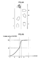
- FIG. 3A diagrammatically shows a process in which a vehicle makes a U-turn.
- FIG. 3B shows an example of the change in turning angle of the vehicle during the process in which the vehicle makes the U-turn.
- the state at the time when the vehicle speed became less than the vehicle speed determining threshold value V 0 is represented as a state "I".
- the turning angle at the state "I" is zero.
- the vehicular longitudinal direction of the vehicle is generally directed to a road width direction.
- the turning angle in the state "III” is about 90 degrees.
- the vehicle further continues the U-turn and a state becomes a state "V" by way of a state “IV”, the vehicle is directed toward an opposite direction of the road.
- the turning angle in the state "V” is about 180 degrees.
- the wrong-way-travel determining part 31 repeatedly determines whether the turning angle exceeds a turnaround determining threshold value ⁇ 0 unless the vehicle speed exceeds the vehicle speed determining threshold value V 0 (S50). If the turnaround determining threshold value ⁇ 0 is set to 90 degrees, the wrong-way-travel determining part 31 detects a wrong-way-travel of the vehicle at the state "III" of FIG. 3A . If the vehicle speed becomes greater than or equal to the vehicle speed determining threshold value V 0 before the turning angle exceeds the turnaround determining threshold value ⁇ 0 , the procedure in FIG. 2 terminates.
- the wrong-way-travel determining part 31 can prevent a false detection of a possibility of a wrong-way-travel.
- the wrong-way-travel determining part 31 determines that the vehicle is about to make a wrong-way-travel, and causes the alarm requesting part 32 to issue a warning to the driver via at least one of an auditory and a visual sense (S60).
- the turnaround determining threshold value ⁇ 0 it is possible to set the turnaround determining threshold value ⁇ 0 to around 80 degrees. On a main lane of a highway, it is rare for a turning angle to become greater than or equal to 80 degrees at a speed below a predetermined speed. Thus, it is not likely to faultily determine a mere lane change as a possible wrong-way-travel and then issue an unnecessary warning. It is also possible to set the turnaround determining threshold value ⁇ 0 to 100 degrees in order to more reliably detect whether there is a possibility of a wrong-way-travel.
- the wrong-way-travel warning device 100 of the present embodiment detects whether a vehicle is traveling on a main lane of a highway, and detects a possibility of a wrong-way-travel based on a vehicle speed and a turning angle only if the vehicle is traveling on the main lane of the highway.
- the wrong-way-travel warning device 100 can issue a warning to a driver before the vehicle starts the wrong-way-travel or just after the vehicle has started the wrong-way-travel, and prevent the wrong-way-travel on a highway from happening.
- the method of the present embodiment can detect whether there is a possibility of a wrong-way-travel.
- the vehicle may make a K-turn.
- the wrong-way-travel warning device 100 can similarly detect whether there is a possibility of a wrong-way-travel.
- FIG. 4A diagrammatically shows a process in which a vehicle makes a U-turn.
- FIG. 4B shows an example of the change in turning angle of the vehicle during the process in which the vehicle makes the U-turn.
- FIG. 4 an explanation about the same parts as those in FIG. 3 is omitted.
- a highway shown in FIG. 4A has two lanes each way. Consequently, the vehicle will be in a state "S" by making a K-turn after the state "III".
- the wrong-way-travel determining part 31 can detect whether there is a possibility of a wrong-way-travel in a state between the state "III" and the state "S".
- the wrong-way-travel determining part 31 can detect whether there is a possibility of a wrong-way-travel regardless of a subsequent K-turn.
- the wrong-way-travel warning device 100 can detect a K-turn based on the signal from the shift position sensor, and prohibit the determination in step S20 even if the vehicle speed becomes greater than or equal to the vehicle speed determining threshold value V 0 in the backward driving. In this way, even if the vehicle speed becomes greater than or equal to the vehicle speed determining threshold value V 0 in the backward driving, the wrong-way-travel warning device 100 can detect whether there is a possibility of a wrong-way-travel around the time of K-turn.
- This embodiment explains about a wrong-way-travel warning device 100 configured to detect whether there is a possibility of a wrong-way-travel by processing an image captured by the rearview camera 26.
- the lane marking has a rectilinear shape parallel to the driving lanes.
- a vehicular longitudinal direction of a vehicle inevitably goes through a state of forming a right angle with the lane marking before the vehicle makes a U-turn and starts a wrong-way-travel.
- the wrong-way-travel warning device 100 can detect whether there is a possibility of a wrong-way-travel by monitoring an angle of the lane marking captured by the rearview camera 26.
- FIG. 5 shows a block diagram of the wrong-way-travel warning device 100 of the present embodiment.
- the wrong-way-travel warning device 100 of the present invention includes a rearview camera 26 and an image processing part 27.
- the rearview camera 26 is arranged roughly in the center of a rear bumper of the vehicle or roughly in the upper center of a rear window so that its optical axis points backward and somewhat downward.
- the rearview camera 26 is comprised of an imaging part incorporating a photoelectric conversion element such as CMOS (Complementary Metal Oxide Semiconductor) or the like.
- CMOS Complementary Metal Oxide Semiconductor
- the rearview camera 26 reads out a voltage of the photoelectric conversion element, and converts the analog signals to digital data having predetermined brightness tones (hereinafter called "image data").
- image data predetermined brightness tones
- the rearview camera 26 is a monochrome camera
- the rearview camera 26 can be a camera capable of taking a color image or a stereo camera.
- the rearview camera 26 captures the image data within a predetermined backward range at the frame speed of 15-30 frames per second, and stores the image data into a memory in sequence.
- the image processing part 27 reads out the image data stored in the memory, recognizes a lane marking, and detects an angle of a vehicular longitudinal direction of the vehicle relative to the lane marking (hereinafter simply called "yaw angle").
- FIG. 6A is a diagram diagrammatically showing a yaw angle of a vehicular longitudinal direction of a vehicle relative to a lane marking.
- the lane marking is detected by using a well known method in the field of, for example, LKAS (Lane Keeping Assist System) or the like.
- LKAS Lane Keeping Assist System
- a piece of the lane marking has an edge which serves as a high frequency component relative to a road surface
- differentiation of brightness values in the image data in the horizontal direction and the vertical direction results in peaks at both ends of a white line, and thus an edge line connecting those peaks can be estimated.
- Plural candidate line pairs for the lane marking are extracted from plural estimated edge lines in consideration of a width of the line marking, and then a piece of a white line recognized as a white line is selected from the plural candidate line pairs for the lane marking by using a method such as matching based on features like a threshold value defined by a brightness or a contrast relative to a road surface, a threshold value of a width, being rectilinear shape, or the like.
- a linear expression of either or both of a left and a right captured white line is obtained by applying Hough transformation to plural edges of the selected white like.
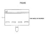
- FIG. 6B and 6C are diagrams illustrating the captured image data and a detection of the vehicular longitudinal direction. If the vehicular longitudinal direction of the vehicle is nearly parallel to the lane marking (the yaw angle is zero degrees), the image data becomes like that shown in FIG. 6B . If the vehicular longitudinal direction of the vehicle is nearly perpendicular to the lane marking (the yaw angle is 90 degrees), the image data becomes like that shown in FIG. 6C .
- an angle ⁇ formed by the captured lane marking and, for example, a predetermined reference line L of the image data is uniquely defined in an one-to-one relationship with the yaw angle.
- the wrong-way-travel warning device 100 can detect a vehicular longitudinal direction (a yaw angle) from the angle ⁇ formed by the captured lane marking and the reference line L.
- a vertical line in the image data is set as the reference line L.
- the wrong-way-travel determining part 31 can detect whether there is a possibility of a wrong-way-travel by determining a yaw angle of the vehicle from the angle ⁇ and comparing the yaw angle with the turnaround determining threshold value ⁇ 0 .
- the flow chart of FIG. 7 is initiated, for example, when a vehicle proceeds onto a highway, and is repeatedly executed at predetermined time intervals.
- the wrong-way-travel determining part 31 of the wrong-way-travel warning device 100 determines whether the vehicle is traveling on a main lane of the highway based on a position of the vehicle (S10). If the vehicle is not traveling on the main lane of the highway (NO in S10), the procedure of FIG. 2 terminates.
- the wrong-way-travel determining part 31 determines whether the vehicle speed detected by the vehicle speed sensor 21 is less than a vehicle speed determining threshold value V 0 (S20).
- the determination in step S20 is similar to that of the first embodiment.
- the wrong-way-travel determining part 31 calculates a yaw angle from the angle ⁇ detected from the image data (S35). As the image data are stored into the memory in sequence, the wrong-way-travel determining part 31 calculates yaw angles from each of the image data.
- the wrong-way-travel determining part 31 determines whether the yaw angle exceeds the turnaround determining threshold value ⁇ 0 (S55).
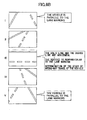
- FIG. 8A diagrammatically shows a process in which a vehicle makes a U-turn.
- FIG. 8B shows an example of image data captured during the U-turn of the vehicle.
- a state at the time when the vehicle speed became less than the vehicle speed determining threshold value V 0 is represented as a state "I".
- the lane marking looks like an inverted V shape in the image data.
- the lane marking in the image data rotates in a clockwise direction and is directed in the horizontal direction in the state "III". That is, in the state "III", the vehicular longitudinal direction of the vehicle and the lane marking are at right angles, and the yaw angle becomes 90 degrees. If the vehicle further continues the U-turn, a state of the vehicle in FIG. 8A becomes a state "V" by way of a state "IV". In conjunction with this, the lane marking in the image data rotates in a clockwise direction and again looks like an inverted V shape in the state "V".
- the wrong-way-travel determining part 31 repeatedly determines whether the yaw angle exceeds the turnaround determining threshold value ⁇ 0 unless the vehicle speed exceeds the vehicle speed determining threshold value V 0 (S55). If the turnaround determining threshold value ⁇ 0 is set to 90 degrees, the wrong-way-travel determining part 31 detects that there is a possibility of a wrong-way-travel of the vehicle in the state "III" of FIG. 8A . Alternatively, if the turnaround determining threshold value ⁇ 0 is set to about 80 degrees, the wrong-way-travel determining part 31 will detect that there is a possibility of a wrong-way-travel earlier. Alternatively, if the turnaround determining threshold value ⁇ 0 is set to 100 degrees, the wrong-way-travel determining part 31 will detect that there is a possibility of a wrong-way-travel more reliably.
- the wrong-way-travel determining part 31 determines that there is a possibility that the vehicle may make a wrong-way-travel and then causes the alarm requesting part 32 to issue a warning to a driver via at least one of an auditory and a visual sense (S60).
- the wrong-way-travel warning device 100 of the present embodiment detects whether there is a possibility of a wrong-way-travel based on the vehicular longitudinal direction (the yaw angle) obtained through an analysis of the vehicle speed and the image data only if the vehicle is on and traveling the main lane of the highway.
- the wrong-way-travel warning device 100 can issue a warning to a driver before or just after a start of the wrong-way-travel and prevent the wrong-way-travel on the highway from happening.
- the wrong-way-travel warning device 100 detects the yaw angle as a numerical value from the image data and compares the yaw angle and the turnaround determining threshold value ⁇ 0 .
- the wrong-way-travel warning device 100 may detect whether there is a possibility of a wrong-way-travel from, for example, the fact that the lane marking of the image data has become horizontal. As the fact that the lane marking of the image data has become horizontal can be detected from the image data only, it is possible to limit the cost increase.
- the wrong-way-travel warning device 100 may detect whether there is a possibility of a wrong-way-travel by detecting that the lane marking which had become horizontal has rotated further in a clockwise direction (a transition from the state "III" to the state "IV” in FIG. 8B ). Setting the transition between states as an object to be determined can facilitate the prevention of a false detection.
- FIG. 8 illustrates the present embodiment by using an example of a three-lane road.
- the wrong-way-travel warning device 100 can similarly calculate the yaw angle or detect the fact that the lane marking of the image data has become horizontal. Even if the vehicle makes a K-turn, the lane marking inevitably becomes horizontal before a start of a wrong-way-travel.
- the wrong-way-travel warning device 100 of the present embodiment can detect whether there is a possibility of a wrong-way-travel regardless of the number of lanes.
Landscapes
- Engineering & Computer Science (AREA)
- Radar, Positioning & Navigation (AREA)
- Remote Sensing (AREA)
- Physics & Mathematics (AREA)
- General Physics & Mathematics (AREA)
- Automation & Control Theory (AREA)
- Chemical & Material Sciences (AREA)
- Combustion & Propulsion (AREA)
- Transportation (AREA)
- Mechanical Engineering (AREA)
- Traffic Control Systems (AREA)
- Navigation (AREA)
Abstract
Description
- The present invention relates to a wrong-way-travel warning device and a wrong-way-travel warning method which issue a warning if there is a possibility that a vehicle may travel the wrong-way on a road whose travel direction is defined.
- A driver drives a vehicle on a road in accordance with a predetermined traveling direction. However, in such a case where there are plural lanes each way, there are some cases where a driver drives a vehicle the wrong-way on the road which the driver has been driving even if the driver intended in the first place to make a U-turn to get to an opposing lane. In this respect, a navigation device which detects wrong-way-travel and warns a vehicle occupant of the wrong-way-travel has been proposed (see
Patent Document 1 for example).Patent Document 1 describes a navigation device which previously stores information about a wrong-way-travel prohibited road in a database and issues a warning to a driver if a vehicle travels in an opposite direction from a forward direction of the wrong-way-travel prohibited road. - A U-turn detecting device configured to detect a U-turn has also been proposed (see Patent Documents 2, 3 for example). Patent Document 2 describes a U-turn detecting device configured to determine that a vehicle has made a U-turn if a turning angle of the vehicle is within a predetermined range and an average curvature during the turning is less than a threshold value. Patent Document 3 describes a U-turn detecting device configured to detect that a vehicle has made a U-turn if both a turnaround of a traveling direction of the vehicle and a crossing of a lane marking are detected within a predetermined time duration.
- A wrong-way-travel detecting device configured to take an image of a forward region by a front camera mounted on a vehicle and to detect a wrung-way-travel based on image processing has also been proposed (see Patent Document 4 for example). Patent Document 4 describes a wrong-way-travel detecting device. The wrong-way-travel detecting device is configured to detect a wrong-way-travel, if a center divider is detected from the image, based on color information of a traffic sign and sizes of traffic signs on the left hand sidle and the right hand side of a road. If a center divider is not detected from the image, the wrong-way-travel detecting device is configured to compare the number of lanes stored in road map information and the number of lanes detected from the image data, and then detect a wrong-way-travel if the number of lanes at the right side of the lane where the vehicle is traveling is less than the number of lanes at the left side of the lane where the vehicle is traveling.
- However, the methods described in
Patent Documents 1 and 4 do not detect a wrong-way-travel until the vehicle actually travels in the opposite direction. Thus, there is a problem in that it is difficult to issue a warning to the driver before the turnaround or before a start of the wrong-way-travel. Similarly, in the case where the U-turn is detected as described in Patent Document 2 or 3, as the vehicle had already turned around toward the opposite direction when the U-turn has been detected, it is difficult to issue a warning to the driver before the turnaround or before a start of the wrong-way-travel. Once the vehicle turns around toward the opposite direction, as it can be difficult for the vehicle to turn back toward the forward direction due to the presence of other vehicles traveling in the forward direction, it is considered to be preferable to issue a warning to the driver before the vehicle turns around. - [Patent Document 1] Japanese Patent Publication No.
2007-139531 - [Patent Document 2] Japanese Patent Publication No.
2006-030116 - [Patent Document 3] Japanese Patent Publication No.
2006-344164 - [Patent Document 4] Japanese Patent Publication No.
2007-140883 - In view of the above-mentioned problems, it is an object of the present invention to provide a wrong-way-travel warning device and a wrong-way-travel warning method capable of detecting a possibility of a wrong-way-travel before a start of the wrong-way-travel.
- To achieve the object above, an embodiment of the present invention provides a wrong-way-travel warning device for detecting a possibility of a wrong-way-travel, comprising a vehicle speed detecting part configured to detect a vehicle speed of a vehicle, a part configured to detect a position of the vehicle, an angle detecting part configured to detect an angle of a vehicular longitudinal direction of the vehicle relative to a lane marking if the vehicle speed of the vehicle becomes less than or equal to a predetermined value, and a warning part configured to issue a warning to an occupant if the position of the vehicle is on a main lane of a highway and if the angle becomes about 90 degrees.
- According to the embodiment of the present invention, as the wrong-way-travel warning device issues a warning to an occupant if the angle becomes about 90 degrees, the wrong-way-travel warning device can issue a warning that there is a possibility of a wrong-way-travel before completing a U-turn, i.e. before a start of the wrong-way-travel.
- It is possible to provide a wrong-way-travel warning device and a wrong-way-travel warning method capable of detecting a possibility of a wrong-way-travel before a start of the wrong-way-travel.
-
-
FIG. 1 is an example of a block diagram of a wrong-way-travel warning device (a first embodiment). -
FIG. 2 is a flow chart showing a procedure in which the wrong-way-travel warning device detects a wrong-way-travel (the first embodiment). -
FIG. 3A is an example of a diagram diagrammatically showing a process in which a vehicle makes a U-turn. -
FIG. 3B is a graph showing an example of the change in turning angle of the vehicle during the process in which the vehicle makes the U-turn. -
FIG. 4A is another example of a diagram diagrammatically showing a process in which a vehicle makes a U-turn. -
FIG. 4B is another graph showing an example of the change in turning angle of the vehicle during the process in which the vehicle makes the U-turn (including a K-turn). -
FIG. 5 is an example of a block diagram of a wrong-way-travel warning device (a second embodiment). -
FIG. 6A is an example of a diagram diagrammatically showing a yaw angle of a vehicular longitudinal direction relative to a lane marking. -
FIG. 6B is an example of a diagram illustrating captured image data and a detection of the vehicular longitudinal direction (yaw angle: 0 degrees). -
FIG. 6C is an example of a diagram illustrating captured image data and a detection of the vehicular longitudinal direction (yaw angle: 90 degrees). -
FIG. 7 is a flow chart showing a procedure in which the wrong-way-travel warning device detects a wrong-way-travel (the second embodiment). -
FIG. 8A is an example of a diagram diagrammatically showing a process in which the vehicle makes a U-turn. -
FIG. 8B is a diagram showing an example of image data during the U-turn of the vehicle. -
- 20
- control part
- 21
- vehicle speed sensor
- 22
- gyro sensor
- 23
- map DB
- 24
- GPS receiver
- 26
- rearview camera
- 31
- wrong-way-travel determining part
- 32
- alarm requesting part
- 100
- wrong-way-travel warning device
- With reference to the figures, the best mode for carrying out the present invention is described below with embodiments.
- On a main lane of a highway, a wrong-way-
travel warning device 100 of the present embodiment is configured to detect a turning angle while setting as a reference a vehicular longitudinal direction at the time when a vehicle speed becomes less than or equal to a predetermined speed. The wrong-way-travel warning device 100 is also configured to detect whether there is a possibility that a vehicle may make a wrong-way-travel by detecting that the turning angle has become a predetermined value (about 90 degrees for example). It is considered that a possibility of making a U-turn on the main lane of the highway is very low due to its structure for preventing U-turns. Therefore, it is possible to reliably detect whether there is a possibility that a vehicle may make a wrong-way-travel on the highway if the turning angle exceeds the predetermined value in the state that the vehicle speed is less than or equal to the predetermined speed on the main lane of the highway. - A highway is connected to ramps for entering the highway, or a side lane, a diverging lane or a merging lane for diverging from or merging into an ordinary road, other lanes on the same highway, or other highways (hereinafter simply called "side lane", including the ramps). A vehicle can travel on the side lane. The side lane may have a bend therein of over 90 degrees or a spiral structure. A highway may also have a rest area where a vehicle can make a left/right turn or a turnaround in the state that the vehicle speed is less than or equal to the predetermined speed. However, the wrong-way-travel warning device of the present embodiment does not make a detection of a possibility of a wrong-way-travel (i.e. a false detection) even if the turning angle exceeds the predetermined value in the state of low speed. This is because the wrong-way-travel warning device of the present embodiment does not detect whether there is a possibility of a wrong-way-travel in the side lane or the rest area.
-
FIG. 1 shows a block diagram of the wrong-way-travel warning device 100 of the present embodiment. The wrong-way-travel warning device 100 is controlled by acontrol part 20. Thecontrol part 20 is connected to avehicle speed sensor 21, agyro sensor 22, a map DB (database) 23, a GPS (Global Positioning System)receiver 24, and ameter panel 25 via a CAN (Controller Area Network) or a dedicated line. Thecontrol part 20 is comprised of, for example, a computer including a CPU, a RAM, a ROM and an input/output interface. For example, a navigation ECU (Electronic Control Unit) configured to control a navigation system can be utilized as the wrong-way-travel warning device 100 as well. The navigation ECU detects a position, speed, and travel direction of a vehicle, and thus equips functions required for an implementation of the wrong-way-travel warning device 100. This can save an in-car space and prevent weight gain. - The
vehicle speed sensor 21 translates a change in magnetic flux at the time when a salient thereof positioned at equally spaced intervals on the circumference of a rotor mounted to each wheel of a vehicle passes the sensor, to a pulse waveform, and measures a wheel speed for each wheel based on the number of pulses per unit time. The vehicle speed is calculated by multiplying the wheel speed by a correction value defined based on an outer diameter of a tire or an interval between the salients. - The
gyro sensor 22 is, for example, a vibrating reed type gyro sensor formed by a micro-machining process. Thegyro sensor 22 can measure Coriolis force which occurs in response to a turning speed of a vehicle as a voltage signal in response to a change in potential between electrodes. A temporal integration of a turning speed i.e. a yaw rate results in a turning angle. Therefore, it is possible to detect a turning angle by a temporal integration of an output of thegyro sensor 22. - The
map DB 23 is comprised of a HDD (Hard Disk Drive), a flash memory, or the like. Themap DB 23 stores road map information associated with positional information such as latitude and longitude. The road map information is a tabular database configured to associate link information about a link constituting a road and node information about a node (a point positioned on an intersection or a point positioned at predetermined intervals on a link) connecting links. The link information includes a link length, a width of road, a node to be connected, a connection direction, or the like. Thus, an actual road network can be reproduced by the road map information. Themap DB 23 also registers for each link a road category such as a highway or an ordinary road, and in the case of a highway, themap DB 23 registers information for discerning a main lane, a side lane, and a rest area. Although there are cases where the term "car-only road" is used as a term having the similar meaning as the term "highway", it will be assumed that the present embodiment utilizes the term "highway" without distinguishing between the term "highway" and the term "car-only road". - The
GPS receiver 24 is configured to acquire preferably four or more GPS satellites orbiting the Earth, and to detect a position of a vehicle (latitude, longitude, and altitude) based on arrival times of radio waves from respective GPS satellites. By correcting for variations in measuring results of GPS signals based on an FM broadcast radio wave sent from a reference station whose position is known, theGPS receiver 24 can detect a more accurate position of the vehicle. - The
control part 20 is configured to accumulate travel distances detected by thevehicle speed sensor 21 in a direction detected by thegyro sensor 22 while setting positional information of a vehicle detected by theGPS receiver 24 as a starting point, and to accurately estimate a position of the vehicle. Thecontrol part 20 is also configured to correct the position of the vehicle through a map matching which matches the position of the vehicle to a most probable road relative to the estimated position by using a road map around the vehicle. - The
meter panel 25 is configured to issue a warning to a driver if a wrong-way-travel is detected, by setting an alarm off, by causing a speaker to output a warning message, or by displaying on a display part such as a liquid crystal display, a head-up display, and so on, a warning message or an icon representing a wrong-way-travel, or the like. Themeter panel 25 may output either an auditory alarm or a visual alarm. - The
control part 20 also has a wrong-way-travel determining part 31 configured to determine whether there is a possibility that a vehicle may make a wrong-way-travel and analarm requesting part 32 configured to request themeter panel 25 to issue a warning if the wrong-way-travel determining part 31 of the wrong-way-travel warning device 100 determines that there is a possibility that the vehicle may make a wrong-way-travel. The wrong-way-travel determining part 31 and thealarm requesting part 32 are implemented by a program executable by a CPU or hardware such as ASIC (Application Specific Integrated Circuit) or the like. - Referring to a flow chart in
FIG. 2 , a procedure in which the wrong-way-travel warning device 100 detects a wrong-way-travel is illustrated. The flow chart inFIG. 2 is initiated, for example, when a vehicle proceeds onto a highway, and is repeatedly executed at predetermined time intervals. - Upon proceeding onto the highway, the wrong-way-
travel determining part 31 determines whether the vehicle is traveling on a main lane of the highway based on a position of the vehicle (S10). The wrong-way-travel determining part 31 may make such a determination by, for example, receiving information that the vehicle is traveling on the main lane of the highway from a communication part installed on a roadside. If the vehicle is not traveling on the main lane of the highway (NO in S10), the procedure ofFIG. 2 terminates. - If the vehicle is traveling on the main lane of the highway (YES in S10), the wrong-way-
travel determining part 31 determines whether the vehicle speed detected by thevehicle speed sensor 21 is less than a vehicle speed determining threshold value V0 (S20). The vehicle speed determining threshold value V0 is a predetermined number. As there is a need to significantly decelerate a vehicle's speed in order to make a U-turn with the vehicle, this general vehicle speed, i.e. the speed at which a vehicle must decelerate to in order to make a U-turn, is set as the vehicle speed determining threshold value (For example, V0 = 20[km/h]). Unless the vehicle speed is less than the vehicle speed determining threshold value V0 (NO in S20), the procedure ofFIG. 2 terminates. - If the vehicle speed is less than the vehicle speed determining threshold value V0 (YES in S20), the wrong-way-
travel determining part 31 records in memory the traveling direction of the vehicle at the time when the vehicle speed became less than the vehicle speed determining threshold value V0 i.e. the traveling direction at the time of determination in step S20 (S30). In this way, the traveling direction at the time when the vehicle speed became less than the vehicle speed determining threshold value V0 is set to zero degrees (a reference value). A processing in step S30 is executed only once so that the traveling direction is not updated as long as the vehicle speed is less than the vehicle speed determining threshold value V0. - Then, the wrong-way-
travel warning device 100 starts to measure a turning angle of the vehicle on the basis of the traveling direction set as zero degrees (S40). As described above, the turning angle can be detected by temporal integrating outputs of thegyro sensor 22. Thus, the turning angle can be detected by, for example, accumulating yaw rates at short time intervals. -
FIG. 3A diagrammatically shows a process in which a vehicle makes a U-turn.FIG. 3B shows an example of the change in turning angle of the vehicle during the process in which the vehicle makes the U-turn. InFIG. 3A , the state at the time when the vehicle speed became less than the vehicle speed determining threshold value V0 is represented as a state "I". Thus, inFIG. 3B , the turning angle at the state "I" is zero. - If the vehicle continues the U-turn and the vehicle's state becomes a state "III" by way of a state "II", the vehicular longitudinal direction of the vehicle is generally directed to a road width direction. Thus, the turning angle in the state "III" is about 90 degrees. If the vehicle further continues the U-turn and a state becomes a state "V" by way of a state "IV", the vehicle is directed toward an opposite direction of the road. Thus, the turning angle in the state "V" is about 180 degrees.
- Referring back to
FIG. 2 , the wrong-way-travel determining part 31 repeatedly determines whether the turning angle exceeds a turnaround determining threshold value θ0 unless the vehicle speed exceeds the vehicle speed determining threshold value V0 (S50). If the turnaround determining threshold value θ0 is set to 90 degrees, the wrong-way-travel determining part 31 detects a wrong-way-travel of the vehicle at the state "III" ofFIG. 3A . If the vehicle speed becomes greater than or equal to the vehicle speed determining threshold value V0 before the turning angle exceeds the turnaround determining threshold value θ0, the procedure inFIG. 2 terminates. Thus, for example, even if the vehicle gets involved in a traffic jam, if the vehicle speed increases before the turning angle exceeds the turnaround determining threshold value θ0, the wrong-way-travel determining part 31 can prevent a false detection of a possibility of a wrong-way-travel. - If the turning angle exceeds the turnaround determining threshold value θ0 (YES in S50), the wrong-way-
travel determining part 31 determines that the vehicle is about to make a wrong-way-travel, and causes thealarm requesting part 32 to issue a warning to the driver via at least one of an auditory and a visual sense (S60). - It is preferable to issue a warning to the driver before the vehicle starts to make a wrong-way-travel even if a possibility of a wrong-way-travel is not always certain. Thus, for example, it is possible to set the turnaround determining threshold value θ0 to around 80 degrees. On a main lane of a highway, it is rare for a turning angle to become greater than or equal to 80 degrees at a speed below a predetermined speed. Thus, it is not likely to faultily determine a mere lane change as a possible wrong-way-travel and then issue an unnecessary warning. It is also possible to set the turnaround determining threshold value θ0 to 100 degrees in order to more reliably detect whether there is a possibility of a wrong-way-travel.
- The wrong-way-
travel warning device 100 of the present embodiment detects whether a vehicle is traveling on a main lane of a highway, and detects a possibility of a wrong-way-travel based on a vehicle speed and a turning angle only if the vehicle is traveling on the main lane of the highway. Thus, the wrong-way-travel warning device 100 can issue a warning to a driver before the vehicle starts the wrong-way-travel or just after the vehicle has started the wrong-way-travel, and prevent the wrong-way-travel on a highway from happening. - As shown in
FIG. 3A , as most highways have plural lanes, it is often the case that it is possible to make a U-turn without making a K-turn if there are, for example, three or more lanes. In such a case, even if there are four or more lanes, the method of the present embodiment can detect whether there is a possibility of a wrong-way-travel. However, in the case where a vehicle is traveling on a highway with two or less lanes or in the case where a vehicle with a large turning radius makes a U-turn on a highway with three lanes, the vehicle may make a K-turn. Even if a vehicle makes a K-turn, the wrong-way-travel warning device 100 can similarly detect whether there is a possibility of a wrong-way-travel. -
FIG. 4A diagrammatically shows a process in which a vehicle makes a U-turn.FIG. 4B shows an example of the change in turning angle of the vehicle during the process in which the vehicle makes the U-turn. InFIG. 4 , an explanation about the same parts as those inFIG. 3 is omitted. A highway shown inFIG. 4A has two lanes each way. Consequently, the vehicle will be in a state "S" by making a K-turn after the state "III". As a turning angle in the state "5" is already close to 180 degrees, even if the turnaround determining threshold value θ0 is set to, for example, 100 degrees, the wrong-way-travel determining part 31 can detect whether there is a possibility of a wrong-way-travel in a state between the state "III" and the state "S". - As the turning angle inevitably becomes horizontal before the start of a wrong-way-travel, if the turnaround determining threshold value θ0 is set to, for example, 80-90 degrees, the wrong-way-
travel determining part 31 can detect whether there is a possibility of a wrong-way-travel regardless of a subsequent K-turn. - If a vehicle makes a K-turn, a shift position sensor indicates a "backward" signal. Thus, the wrong-way-
travel warning device 100 can detect a K-turn based on the signal from the shift position sensor, and prohibit the determination in step S20 even if the vehicle speed becomes greater than or equal to the vehicle speed determining threshold value V0 in the backward driving. In this way, even if the vehicle speed becomes greater than or equal to the vehicle speed determining threshold value V0 in the backward driving, the wrong-way-travel warning device 100 can detect whether there is a possibility of a wrong-way-travel around the time of K-turn. - This embodiment explains about a wrong-way-
travel warning device 100 configured to detect whether there is a possibility of a wrong-way-travel by processing an image captured by therearview camera 26. There is a lane marking marked on a road for marking off driving lanes on a highway. The lane marking has a rectilinear shape parallel to the driving lanes. Thus, it is considered that a vehicular longitudinal direction of a vehicle inevitably goes through a state of forming a right angle with the lane marking before the vehicle makes a U-turn and starts a wrong-way-travel. Thus, the wrong-way-travel warning device 100 can detect whether there is a possibility of a wrong-way-travel by monitoring an angle of the lane marking captured by therearview camera 26. -
FIG. 5 shows a block diagram of the wrong-way-travel warning device 100 of the present embodiment. InFIG. 5 , the same component parts as those inFIG. 1 are referenced by the same reference number and their explanations are omitted. The wrong-way-travel warning device 100 of the present invention includes arearview camera 26 and animage processing part 27. - The
rearview camera 26 is arranged roughly in the center of a rear bumper of the vehicle or roughly in the upper center of a rear window so that its optical axis points backward and somewhat downward. Therearview camera 26 is comprised of an imaging part incorporating a photoelectric conversion element such as CMOS (Complementary Metal Oxide Semiconductor) or the like. Therearview camera 26 reads out a voltage of the photoelectric conversion element, and converts the analog signals to digital data having predetermined brightness tones (hereinafter called "image data"). Although therearview camera 26 is a monochrome camera, therearview camera 26 can be a camera capable of taking a color image or a stereo camera. Therearview camera 26 captures the image data within a predetermined backward range at the frame speed of 15-30 frames per second, and stores the image data into a memory in sequence. - The
image processing part 27 reads out the image data stored in the memory, recognizes a lane marking, and detects an angle of a vehicular longitudinal direction of the vehicle relative to the lane marking (hereinafter simply called "yaw angle").FIG. 6A is a diagram diagrammatically showing a yaw angle of a vehicular longitudinal direction of a vehicle relative to a lane marking. The lane marking is detected by using a well known method in the field of, for example, LKAS (Lane Keeping Assist System) or the like. Specifically, as a piece of the lane marking has an edge which serves as a high frequency component relative to a road surface, differentiation of brightness values in the image data in the horizontal direction and the vertical direction results in peaks at both ends of a white line, and thus an edge line connecting those peaks can be estimated. Plural candidate line pairs for the lane marking are extracted from plural estimated edge lines in consideration of a width of the line marking, and then a piece of a white line recognized as a white line is selected from the plural candidate line pairs for the lane marking by using a method such as matching based on features like a threshold value defined by a brightness or a contrast relative to a road surface, a threshold value of a width, being rectilinear shape, or the like. A linear expression of either or both of a left and a right captured white line is obtained by applying Hough transformation to plural edges of the selected white like. -
FIG. 6B and6C are diagrams illustrating the captured image data and a detection of the vehicular longitudinal direction. If the vehicular longitudinal direction of the vehicle is nearly parallel to the lane marking (the yaw angle is zero degrees), the image data becomes like that shown inFIG. 6B . If the vehicular longitudinal direction of the vehicle is nearly perpendicular to the lane marking (the yaw angle is 90 degrees), the image data becomes like that shown inFIG. 6C . Here, as an angle formed by the optical axis of therearview camera 26 and the road surface remains fixed, an angle α formed by the captured lane marking and, for example, a predetermined reference line L of the image data, is uniquely defined in an one-to-one relationship with the yaw angle. - Therefore, if the angle α formed by the captured lane marking and the reference line L is previously registered in relation to the yaw angle, the wrong-way-
travel warning device 100 can detect a vehicular longitudinal direction (a yaw angle) from the angle α formed by the captured lane marking and the reference line L. InFIG. 6B and6C , a vertical line in the image data is set as the reference line L. - Therefore, the wrong-way-
travel determining part 31 can detect whether there is a possibility of a wrong-way-travel by determining a yaw angle of the vehicle from the angle α and comparing the yaw angle with the turnaround determining threshold value θ0. - Referring to the flow chart shown in
FIG. 7 , a procedure in which the wrong-way-travel warning device 100 detects a wrong-way-travel is illustrated. The flow chart ofFIG. 7 is initiated, for example, when a vehicle proceeds onto a highway, and is repeatedly executed at predetermined time intervals. - Upon proceeding onto the highway, the wrong-way-
travel determining part 31 of the wrong-way-travel warning device 100 determines whether the vehicle is traveling on a main lane of the highway based on a position of the vehicle (S10). If the vehicle is not traveling on the main lane of the highway (NO in S10), the procedure ofFIG. 2 terminates. - If the vehicle is traveling on the main lane of the highway (YES in S10), the wrong-way-
travel determining part 31 determines whether the vehicle speed detected by thevehicle speed sensor 21 is less than a vehicle speed determining threshold value V0 (S20). The determination in step S20 is similar to that of the first embodiment. - If the vehicle speed is less than the vehicle speed determining threshold value V0 (YES in S20), the wrong-way-
travel determining part 31 calculates a yaw angle from the angle α detected from the image data (S35). As the image data are stored into the memory in sequence, the wrong-way-travel determining part 31 calculates yaw angles from each of the image data. - Then, the wrong-way-
travel determining part 31 determines whether the yaw angle exceeds the turnaround determining threshold value θ0 (S55). -
FIG. 8A diagrammatically shows a process in which a vehicle makes a U-turn.FIG. 8B shows an example of image data captured during the U-turn of the vehicle. InFIG. 8A , a state at the time when the vehicle speed became less than the vehicle speed determining threshold value V0 is represented as a state "I". As the vehicular longitudinal direction of the vehicle is nearly parallel to the lane marking in the state "I", similar toFIG. 6B , the lane marking looks like an inverted V shape in the image data. - If the vehicle continues the U-turn, the lane marking in the image data rotates in a clockwise direction and is directed in the horizontal direction in the state "III". That is, in the state "III", the vehicular longitudinal direction of the vehicle and the lane marking are at right angles, and the yaw angle becomes 90 degrees. If the vehicle further continues the U-turn, a state of the vehicle in
FIG. 8A becomes a state "V" by way of a state "IV". In conjunction with this, the lane marking in the image data rotates in a clockwise direction and again looks like an inverted V shape in the state "V". - Referring back to
FIG. 7 , the wrong-way-travel determining part 31 repeatedly determines whether the yaw angle exceeds the turnaround determining threshold value θ0 unless the vehicle speed exceeds the vehicle speed determining threshold value V0 (S55). If the turnaround determining threshold value θ0 is set to 90 degrees, the wrong-way-travel determining part 31 detects that there is a possibility of a wrong-way-travel of the vehicle in the state "III" ofFIG. 8A . Alternatively, if the turnaround determining threshold value θ0 is set to about 80 degrees, the wrong-way-travel determining part 31 will detect that there is a possibility of a wrong-way-travel earlier. Alternatively, if the turnaround determining threshold value θ0 is set to 100 degrees, the wrong-way-travel determining part 31 will detect that there is a possibility of a wrong-way-travel more reliably. - If the yaw angle exceeds the turnaround determining threshold value θ0 (YES in S55), the wrong-way-
travel determining part 31 determines that there is a possibility that the vehicle may make a wrong-way-travel and then causes thealarm requesting part 32 to issue a warning to a driver via at least one of an auditory and a visual sense (S60). - The wrong-way-
travel warning device 100 of the present embodiment detects whether there is a possibility of a wrong-way-travel based on the vehicular longitudinal direction (the yaw angle) obtained through an analysis of the vehicle speed and the image data only if the vehicle is on and traveling the main lane of the highway. Thus, the wrong-way-travel warning device 100 can issue a warning to a driver before or just after a start of the wrong-way-travel and prevent the wrong-way-travel on the highway from happening. - In the present embodiment, the wrong-way-
travel warning device 100 detects the yaw angle as a numerical value from the image data and compares the yaw angle and the turnaround determining threshold value θ0. However, the wrong-way-travel warning device 100 may detect whether there is a possibility of a wrong-way-travel from, for example, the fact that the lane marking of the image data has become horizontal. As the fact that the lane marking of the image data has become horizontal can be detected from the image data only, it is possible to limit the cost increase. This is because there is no need to previously register the angle α formed by the captured lane marking and the reference line in relation to the yaw angle, in so far as the optical axis of therearview camera 26 is perpendicular to a wheel axis. Alternatively, in this case, the wrong-way-travel warning device 100 may detect whether there is a possibility of a wrong-way-travel by detecting that the lane marking which had become horizontal has rotated further in a clockwise direction (a transition from the state "III" to the state "IV" inFIG. 8B ). Setting the transition between states as an object to be determined can facilitate the prevention of a false detection. -
FIG. 8 illustrates the present embodiment by using an example of a three-lane road. However, even in a single-lane road or a two-lane road, as therearview camera 26 captures either a left or a right lane marking, the wrong-way-travel warning device 100 can similarly calculate the yaw angle or detect the fact that the lane marking of the image data has become horizontal. Even if the vehicle makes a K-turn, the lane marking inevitably becomes horizontal before a start of a wrong-way-travel. Thus, similar to the first embodiment, the wrong-way-travel warning device 100 of the present embodiment can detect whether there is a possibility of a wrong-way-travel regardless of the number of lanes. - The present international application claims priority from Japanese Patent Application No.
2008-103498 filed on April 11, 2008
Claims (4)
- A wrong-way-travel warning device for detecting a possibility of a wrong-way-travel, comprising:a vehicle speed detecting part configured to detect a vehicle speed of a vehicle;a part configured to detect a position of the vehicle;an angle detecting part configured to detect an angle of a vehicular longitudinal direction of the vehicle relative to a lane marking if the vehicle speed of the vehicle becomes less than or equal to a predetermined value; anda wrong-way-travel detecting part configured to detect a possibility of a wrong-way-travel if the position of the vehicle is on a main lane of a highway and if the angle becomes about 90 degrees.
- A wrong-way-travel warning device according to claim 1, wherein the angle detecting part is configured to detect the angle by temporal integrating a yaw rate while setting as a reference the vehicular longitudinal direction at the time when the vehicle speed becomes less than or equal to the predetermined value.
- A wrong-way-travel warning device according to claim 1 or 2, further comprising:a warning part configured to issue a warning to a vehicle occupant if the wrong-way-travel detecting part detects that there is a possibility of a wrong-way-travel.
- A wrong-way-travel warning method for detecting a possibility of a wrong-way-travel, comprising the steps of:detecting by a vehicle speed detecting part a vehicle speed of a vehicle;detecting that the vehicle is traveling on a main lane of a highway;detecting by an angle detecting part an angle of a vehicular longitudinal direction of the vehicle relative to a lane marking if the vehicle speed of the vehicle becomes less than or equal to a predetermined value; anddetecting by a wrong-way-travel detecting part that there is a possibility of a wrong-way-travel if the angle becomes about 90 degrees.
Applications Claiming Priority (2)
| Application Number | Priority Date | Filing Date | Title |
|---|---|---|---|
| JP2008103498A JP5015849B2 (en) | 2008-04-11 | 2008-04-11 | Reverse running warning device, reverse running warning method |
| PCT/JP2009/057278 WO2009125815A1 (en) | 2008-04-11 | 2009-04-09 | Wrong-way travel warning device and wrong-way travel warning method |
Publications (3)
| Publication Number | Publication Date |
|---|---|
| EP2261603A1 true EP2261603A1 (en) | 2010-12-15 |
| EP2261603A4 EP2261603A4 (en) | 2013-05-01 |
| EP2261603B1 EP2261603B1 (en) | 2014-05-21 |
Family
ID=41161947
Family Applications (1)
| Application Number | Title | Priority Date | Filing Date |
|---|---|---|---|
| EP09729667.7A Not-in-force EP2261603B1 (en) | 2008-04-11 | 2009-04-09 | Wrong-way travel warning device and wrong-way travel warning method |
Country Status (5)
| Country | Link |
|---|---|
| US (1) | US8421648B2 (en) |
| EP (1) | EP2261603B1 (en) |
| JP (1) | JP5015849B2 (en) |
| CN (1) | CN101765757B (en) |
| WO (1) | WO2009125815A1 (en) |
Cited By (1)
| Publication number | Priority date | Publication date | Assignee | Title |
|---|---|---|---|---|
| US12296855B2 (en) | 2021-04-09 | 2025-05-13 | Waymo Llc | Unmapped U-turn behavior prediction using machine learning |
Families Citing this family (62)
| Publication number | Priority date | Publication date | Assignee | Title |
|---|---|---|---|---|
| JP5273387B2 (en) * | 2009-08-24 | 2013-08-28 | アイシン・エィ・ダブリュ株式会社 | Driving support device, driving support method, and driving support program |
| JP5482320B2 (en) * | 2010-03-11 | 2014-05-07 | 株式会社デンソー | Vehicle driving support device |
| JP5666812B2 (en) | 2010-03-12 | 2015-02-12 | クラリオン株式会社 | Vehicle reverse running detection device |
| DE102010025379A1 (en) * | 2010-06-28 | 2011-12-29 | Technische Universität Dortmund | Method for detecting and warning of wrong-way drivers as well as wrong-way reporting and warning system |
| JP5545109B2 (en) * | 2010-08-05 | 2014-07-09 | アイシン・エィ・ダブリュ株式会社 | Driving support device, information distribution device, driving support method, information distribution method, and computer program |
| JP5418448B2 (en) * | 2010-09-08 | 2014-02-19 | 株式会社デンソー | Vehicle reverse running detection device |
| JP5229293B2 (en) * | 2010-10-01 | 2013-07-03 | 株式会社デンソー | Vehicle driving support device |
| DE102010052129A1 (en) * | 2010-11-22 | 2012-06-06 | GM Global Technology Operations LLC | Method for operating a motor vehicle and motor vehicle |
| DE102010052128A1 (en) | 2010-11-22 | 2012-05-24 | GM Global Technology Operations LLC | Method for operating a motor vehicle and motor vehicle |
| JP5479398B2 (en) * | 2011-03-29 | 2014-04-23 | アイシン・エィ・ダブリュ株式会社 | Driving support device, driving support method, and computer program |
| JP5796740B2 (en) * | 2011-12-09 | 2015-10-21 | アイシン・エィ・ダブリュ株式会社 | Traffic information notification system, traffic information notification program, and traffic information notification method |
| US9024785B2 (en) * | 2011-12-27 | 2015-05-05 | Aisin Aw Co., Ltd. | Traffic information distribution system and traffic information system, traffic information distribution program, and traffic information distribution method |
| US9309004B2 (en) * | 2012-09-21 | 2016-04-12 | Merlin Technology, Inc. | Centripetal acceleration determination, centripetal acceleration based velocity tracking system and methods |
| CN103198670B (en) * | 2013-03-18 | 2015-11-11 | 陕西科技大学 | A kind of device and detection method thereof detecting the reversing automobile behavior of high speed fork in the road |
| DE102013209502B4 (en) * | 2013-05-22 | 2025-01-23 | Robert Bosch Gmbh | Method for automatically intervening in an ego vehicle during a wrong-way drive, in particular a ghost drive |
| DE102014208617A1 (en) * | 2013-09-06 | 2015-03-12 | Robert Bosch Gmbh | Method and control and detection device for plausibility of a wrong-way drive of a motor vehicle |
| DE102014208622A1 (en) * | 2013-09-06 | 2015-03-12 | Robert Bosch Gmbh | Method and control and detection device for plausibility of a wrong-way drive of a motor vehicle |
| DE102014210411A1 (en) | 2013-09-06 | 2015-03-12 | Robert Bosch Gmbh | Method and control and detection device for plausibility of a wrong-way drive of a motor vehicle |
| DE102014208659A1 (en) * | 2013-09-06 | 2015-03-12 | Robert Bosch Gmbh | System for transmitting information in the determination of wrong-way driving of a motor vehicle, associated transmitting and receiving devices and corresponding transmitting and receiving methods |
| DE102014208673A1 (en) * | 2013-09-06 | 2015-03-12 | Robert Bosch Gmbh | Method and traffic monitoring device for detecting a wrong-way drive of a motor vehicle |
| DE102013224171B4 (en) * | 2013-11-26 | 2025-11-13 | Robert Bosch Gmbh | Method and control and recording device for detecting the entry of a motor vehicle into a lane of a road against the direction of travel |
| DE102013224303A1 (en) * | 2013-11-27 | 2015-05-28 | Robert Bosch Gmbh | Method and control unit for situation-dependent power steering in a lane departure warning for a vehicle |
| JP6237214B2 (en) * | 2013-12-24 | 2017-11-29 | 株式会社デンソー | Reverse running detection device |
| PT2894616E (en) * | 2014-01-14 | 2016-02-29 | Kapsch Trafficcom Ag | Onboard unit and driver information method |
| JP6141787B2 (en) * | 2014-04-01 | 2017-06-07 | 本田技研工業株式会社 | Lane mark recognition device |
| US9849834B2 (en) * | 2014-06-11 | 2017-12-26 | Ford Gloabl Technologies, L.L.C. | System and method for improving vehicle wrong-way detection |
| DE102015213517A1 (en) * | 2015-07-17 | 2017-01-19 | Robert Bosch Gmbh | Method and device for warning other road users of a wrong-moving vehicle |
| CA2994391A1 (en) * | 2015-07-31 | 2017-02-09 | Nissan Motor Co., Ltd. | Travel control method and travel control apparatus |
| DE102015215380A1 (en) * | 2015-08-12 | 2017-02-16 | Robert Bosch Gmbh | Method and device for securing a wrong-way driver information |
| DE102015217792B4 (en) * | 2015-09-17 | 2022-07-14 | Volkswagen Aktiengesellschaft | Device, method and computer program for providing information about the end of a traffic jam via a vehicle-to-vehicle interface |
| JP6451584B2 (en) * | 2015-10-09 | 2019-01-16 | 株式会社デンソー | Information processing device |
| JP6532593B2 (en) * | 2016-03-01 | 2019-06-19 | 三菱電機株式会社 | Reverse run suppression device, reverse run suppression method and reverse run suppression system |
| JP6704792B2 (en) * | 2016-05-26 | 2020-06-03 | クラリオン株式会社 | Warning device |
| JP6654544B2 (en) * | 2016-10-21 | 2020-02-26 | 株式会社Soken | Sensor control device |
| DE102016220947A1 (en) * | 2016-10-25 | 2018-06-28 | Ford Global Technologies, Llc | Driver assistance system |
| US10274335B2 (en) * | 2017-01-03 | 2019-04-30 | Honda Motor Co., Ltd. | System for providing a notification of a presence of an occupant in a vehicle through historical patterns and method thereof |
| US10160459B2 (en) * | 2017-03-22 | 2018-12-25 | Ford Global Technologies, Llc | Vehicle lane direction detection |
| US10442429B2 (en) * | 2017-03-30 | 2019-10-15 | Ford Global Technologies, Llc | Wrong-way vehicle detection |
| US20180365989A1 (en) * | 2017-06-20 | 2018-12-20 | GM Global Technology Operations LLC | System and method for wrong-way driving detection and mitigation |
| DE102017214969B4 (en) * | 2017-08-28 | 2024-05-29 | Robert Bosch Gmbh | Method and device for warning a vehicle of wrong-way travel after an accident and/or a safety-critical driving situation, in particular after a temporary standstill of the vehicle |
| DE102017219883A1 (en) * | 2017-11-08 | 2019-05-09 | Robert Bosch Gmbh | An apparatus, server, and method for determining a wrong trip and providing a warning about the random check |
| DE102017222791A1 (en) * | 2017-12-14 | 2019-06-19 | Robert Bosch Gmbh | Method and system for warning road users of a wrong-way drive of a vehicle with transmitter data control |
| DE102017222787A1 (en) * | 2017-12-14 | 2019-06-19 | Robert Bosch Gmbh | Method and system for warning road users of a wrong-way vehicle with optimized wrong-way driver rating |
| US10417909B1 (en) * | 2018-02-26 | 2019-09-17 | Verizon Connect Ireland Ltd. | Identifying wrong-way travel events |
| US11062063B2 (en) * | 2018-04-09 | 2021-07-13 | International Business Machines Corporation | System and method for generating vehicle travel data |
| JP7014032B2 (en) | 2018-04-23 | 2022-02-01 | 株式会社デンソー | Vehicle collision estimation device |
| US10926766B2 (en) | 2018-06-18 | 2021-02-23 | Toyota Motor Engineering & Manufacturing North America, Inc. | One-way direction sensing system |
| CN109884338B (en) * | 2019-04-11 | 2021-04-27 | 武汉小安科技有限公司 | Method, device, equipment and storage medium for detecting reverse running of shared electric vehicle |
| JP7505167B2 (en) * | 2019-06-10 | 2024-06-25 | 日本電気株式会社 | Driving management device, driving management method, and program |
| CN110718059A (en) * | 2019-10-10 | 2020-01-21 | 福州卓立信息科技有限公司 | Anti-retrograde device based on 5G Internet of things and judgment method |
| US11127288B2 (en) * | 2019-12-05 | 2021-09-21 | Geotoll, Inc. | Wrong way driving detection |
| US11180165B2 (en) * | 2019-12-26 | 2021-11-23 | Baidu Usa Llc | Autonomous driving vehicle three-point turn |
| DE102020202256A1 (en) | 2020-02-21 | 2021-08-26 | Hyundai Motor Company | METHOD OF DETECTING WRONG DRIVING SITUATIONS OF A VEHICLE, METHOD OF DETECTING ONE-WAY TRAVELING SITUATIONS OF A VEHICLE, AND VEHICLE |
| CN112233442A (en) * | 2020-09-11 | 2021-01-15 | 浙江吉利控股集团有限公司 | Retrograde warning method and system applied to vehicles |
| CN116601690A (en) * | 2020-12-10 | 2023-08-15 | 三菱电机株式会社 | Retrograde judging device and retrograde judging method |
| US11505206B2 (en) | 2020-12-14 | 2022-11-22 | GM Global Technology Operations LLC | Wrong-way driving detection and collision mitigation |
| US11535271B2 (en) * | 2021-01-08 | 2022-12-27 | Argo AI, LLC | Methods and systems for monitoring vehicle motion with driver safety alerts |
| CN113183983B (en) * | 2021-04-07 | 2024-01-30 | 浙江吉利控股集团有限公司 | Method, apparatus, electronic device, storage medium, and program product for controlling vehicle |
| CN113619712B (en) * | 2021-08-19 | 2023-03-24 | 湖南喜宝达信息科技有限公司 | Electric bicycle and control method and storage medium for automatic power-off in reverse running of electric bicycle |
| KR20230030850A (en) * | 2021-08-26 | 2023-03-07 | 현대자동차주식회사 | Method and apparatus for providing broadcasting information based on machine learning |
| CN118470987A (en) * | 2024-04-18 | 2024-08-09 | 北京精英智通科技股份有限公司 | Method and device for detecting vehicle running direction and electronic equipment |
| FR3164164A1 (en) * | 2024-07-02 | 2026-01-09 | Ampere Sas | Vehicle and method for anticipating a situation of driving in the wrong direction |
Family Cites Families (13)
| Publication number | Priority date | Publication date | Assignee | Title |
|---|---|---|---|---|
| US3824469A (en) * | 1972-06-16 | 1974-07-16 | M Ristenbatt | Comprehensive automatic vehicle communication, paging, and position location system |
| US5043902A (en) * | 1987-12-28 | 1991-08-27 | Aisin Aw Co., Ltd. | Vehicular navigation apparatus |
| US5390122A (en) * | 1993-05-07 | 1995-02-14 | Lectron Products, Inc. | Method and apparatus for calibrating a vehicle compass system |
| JPH0939602A (en) | 1995-08-04 | 1997-02-10 | Mitsubishi Motors Corp | Vehicle running condition determination device |
| JPH0981757A (en) | 1995-09-18 | 1997-03-28 | Mitsubishi Electric Corp | Vehicle position detection device |
| JP2002312897A (en) * | 2001-04-11 | 2002-10-25 | Denso Corp | Violation reporting device and traffic violation control system |
| JP4440027B2 (en) * | 2004-07-21 | 2010-03-24 | アルパイン株式会社 | U-turn detection device and U-turn detection method |
| JP2006344164A (en) | 2005-06-10 | 2006-12-21 | Denso Corp | Vehicle turning detection device and vehicle navigation device including the device |
| JP2007139531A (en) | 2005-11-17 | 2007-06-07 | Hitachi Software Eng Co Ltd | System for preventing reverse running of vehicle and vehicle-mounted car navigation system |
| JP4557299B2 (en) * | 2005-11-18 | 2010-10-06 | アルパイン株式会社 | Reverse rotation detection device using a camera |
| JP2007293390A (en) | 2006-04-20 | 2007-11-08 | Fujifilm Corp | Reverse running alarm device |
| JP2008103498A (en) | 2006-10-18 | 2008-05-01 | Dowa Electronics Materials Co Ltd | Light-emitting element |
| JP4879082B2 (en) * | 2007-05-01 | 2012-02-15 | アルパイン株式会社 | Warning guidance device and warning guidance method |
-
2008
- 2008-04-11 JP JP2008103498A patent/JP5015849B2/en not_active Expired - Fee Related
-
2009
- 2009-04-09 US US12/671,291 patent/US8421648B2/en not_active Expired - Fee Related
- 2009-04-09 EP EP09729667.7A patent/EP2261603B1/en not_active Not-in-force
- 2009-04-09 CN CN2009801000491A patent/CN101765757B/en not_active Expired - Fee Related
- 2009-04-09 WO PCT/JP2009/057278 patent/WO2009125815A1/en not_active Ceased
Cited By (1)
| Publication number | Priority date | Publication date | Assignee | Title |
|---|---|---|---|---|
| US12296855B2 (en) | 2021-04-09 | 2025-05-13 | Waymo Llc | Unmapped U-turn behavior prediction using machine learning |
Also Published As
| Publication number | Publication date |
|---|---|
| CN101765757B (en) | 2012-07-04 |
| US20110121992A1 (en) | 2011-05-26 |
| JP5015849B2 (en) | 2012-08-29 |
| WO2009125815A1 (en) | 2009-10-15 |
| US8421648B2 (en) | 2013-04-16 |
| EP2261603B1 (en) | 2014-05-21 |
| CN101765757A (en) | 2010-06-30 |
| JP2009250964A (en) | 2009-10-29 |
| EP2261603A4 (en) | 2013-05-01 |
Similar Documents
| Publication | Publication Date | Title |
|---|---|---|
| EP2261603B1 (en) | Wrong-way travel warning device and wrong-way travel warning method | |
| EP2253936B1 (en) | Current position determining device and current position determining nethod | |
| EP3226022B1 (en) | Notification device of an approaching vehicle | |
| US10325494B2 (en) | Route guidance device and route guidance method | |
| US9734718B2 (en) | Vehicle location estimation apparatus and vehicle location estimation method | |
| EP2492888A2 (en) | Lane departure warning apparatus and system | |
| EP2439713B1 (en) | In-vehicle information processing device | |
| EP2141678A1 (en) | Driving support system | |
| US10369995B2 (en) | Information processing device, information processing method, control device for vehicle, and control method for vehicle | |
| US10573175B2 (en) | Systems and methods for traffic sign validation | |
| CN101256713A (en) | Driving support system and vehicle-mounted device | |
| US11715373B2 (en) | Traffic light visibility detection and augmented display | |
| US20170178591A1 (en) | Sign display apparatus and method for vehicle | |
| CN102542835B (en) | There is navigational system and the air navigation aid of traffic jam recognition function | |
| JP2019211416A (en) | Driving assistance device | |
| JP5536976B2 (en) | Navigation device | |
| JP5107125B2 (en) | Reverse running warning device, reverse running warning method | |
| JP2011095960A (en) | Reverse travel alarm device | |
| JP5227220B2 (en) | Reverse running warning device | |
| JP2006277547A (en) | Vehicle driving assistance device | |
| CN110395270B (en) | Automatic following driving system | |
| JP7028601B2 (en) | Reverse run notification device | |
| KR20170129466A (en) | System for Displaying a Conditional Limiting Speed of Vehicle | |
| JP2022035730A (en) | Control device and controlling method | |
| CN113936451A (en) | Traffic detection system and traffic detection method |
Legal Events
| Date | Code | Title | Description |
|---|---|---|---|
| PUAI | Public reference made under article 153(3) epc to a published international application that has entered the european phase |
Free format text: ORIGINAL CODE: 0009012 |
|
| 17P | Request for examination filed |
Effective date: 20100129 |
|
| AK | Designated contracting states |
Kind code of ref document: A1 Designated state(s): AT BE BG CH CY CZ DE DK EE ES FI FR GB GR HR HU IE IS IT LI LT LU LV MC MK MT NL NO PL PT RO SE SI SK TR |
|
| AX | Request for extension of the european patent |
Extension state: AL BA RS |
|
| DAX | Request for extension of the european patent (deleted) | ||
| RAP1 | Party data changed (applicant data changed or rights of an application transferred) |
Owner name: AISIN AW CO., LTD. Owner name: TOYOTA JIDOSHA KABUSHIKI KAISHA Owner name: DENSO CORPORATION |
|
| A4 | Supplementary search report drawn up and despatched |
Effective date: 20130402 |
|
| RIC1 | Information provided on ipc code assigned before grant |
Ipc: B62D 15/02 20060101ALI20130325BHEP Ipc: G01C 21/36 20060101ALI20130325BHEP Ipc: G08G 1/16 20060101ALI20130325BHEP Ipc: G08G 1/0969 20060101ALI20130325BHEP Ipc: G01C 21/26 20060101AFI20130325BHEP |
|
| REG | Reference to a national code |
Ref country code: DE Ref legal event code: R079 Ref document number: 602009024255 Country of ref document: DE Free format text: PREVIOUS MAIN CLASS: G01C0021000000 Ipc: G01C0021260000 |
|
| RIC1 | Information provided on ipc code assigned before grant |
Ipc: G08G 1/0969 20060101ALI20130916BHEP Ipc: B62D 15/02 20060101ALI20130916BHEP Ipc: G08G 1/16 20060101ALI20130916BHEP Ipc: G01C 21/36 20060101ALI20130916BHEP Ipc: G01C 21/26 20060101AFI20130916BHEP |
|
| GRAP | Despatch of communication of intention to grant a patent |
Free format text: ORIGINAL CODE: EPIDOSNIGR1 |
|
| INTG | Intention to grant announced |
Effective date: 20140102 |
|
| GRAS | Grant fee paid |
Free format text: ORIGINAL CODE: EPIDOSNIGR3 |
|
| GRAA | (expected) grant |
Free format text: ORIGINAL CODE: 0009210 |
|
| AK | Designated contracting states |
Kind code of ref document: B1 Designated state(s): AT BE BG CH CY CZ DE DK EE ES FI FR GB GR HR HU IE IS IT LI LT LU LV MC MK MT NL NO PL PT RO SE SI SK TR |
|
| REG | Reference to a national code |
Ref country code: GB Ref legal event code: FG4D |
|
| REG | Reference to a national code |
Ref country code: CH Ref legal event code: EP |
|
| REG | Reference to a national code |
Ref country code: AT Ref legal event code: REF Ref document number: 669809 Country of ref document: AT Kind code of ref document: T Effective date: 20140615 |
|
| REG | Reference to a national code |
Ref country code: IE Ref legal event code: FG4D |
|
| REG | Reference to a national code |
Ref country code: DE Ref legal event code: R096 Ref document number: 602009024255 Country of ref document: DE Effective date: 20140703 |
|
| REG | Reference to a national code |
Ref country code: NL Ref legal event code: VDEP Effective date: 20140521 Ref country code: AT Ref legal event code: MK05 Ref document number: 669809 Country of ref document: AT Kind code of ref document: T Effective date: 20140521 |
|
| REG | Reference to a national code |
Ref country code: LT Ref legal event code: MG4D |
|
| PG25 | Lapsed in a contracting state [announced via postgrant information from national office to epo] |
Ref country code: FI Free format text: LAPSE BECAUSE OF FAILURE TO SUBMIT A TRANSLATION OF THE DESCRIPTION OR TO PAY THE FEE WITHIN THE PRESCRIBED TIME-LIMIT Effective date: 20140521 Ref country code: IS Free format text: LAPSE BECAUSE OF FAILURE TO SUBMIT A TRANSLATION OF THE DESCRIPTION OR TO PAY THE FEE WITHIN THE PRESCRIBED TIME-LIMIT Effective date: 20140921 Ref country code: NO Free format text: LAPSE BECAUSE OF FAILURE TO SUBMIT A TRANSLATION OF THE DESCRIPTION OR TO PAY THE FEE WITHIN THE PRESCRIBED TIME-LIMIT Effective date: 20140821 Ref country code: LT Free format text: LAPSE BECAUSE OF FAILURE TO SUBMIT A TRANSLATION OF THE DESCRIPTION OR TO PAY THE FEE WITHIN THE PRESCRIBED TIME-LIMIT Effective date: 20140521 Ref country code: GR Free format text: LAPSE BECAUSE OF FAILURE TO SUBMIT A TRANSLATION OF THE DESCRIPTION OR TO PAY THE FEE WITHIN THE PRESCRIBED TIME-LIMIT Effective date: 20140822 |
|
| PG25 | Lapsed in a contracting state [announced via postgrant information from national office to epo] |
Ref country code: HR Free format text: LAPSE BECAUSE OF FAILURE TO SUBMIT A TRANSLATION OF THE DESCRIPTION OR TO PAY THE FEE WITHIN THE PRESCRIBED TIME-LIMIT Effective date: 20140521 Ref country code: ES Free format text: LAPSE BECAUSE OF FAILURE TO SUBMIT A TRANSLATION OF THE DESCRIPTION OR TO PAY THE FEE WITHIN THE PRESCRIBED TIME-LIMIT Effective date: 20140521 Ref country code: AT Free format text: LAPSE BECAUSE OF FAILURE TO SUBMIT A TRANSLATION OF THE DESCRIPTION OR TO PAY THE FEE WITHIN THE PRESCRIBED TIME-LIMIT Effective date: 20140521 Ref country code: LV Free format text: LAPSE BECAUSE OF FAILURE TO SUBMIT A TRANSLATION OF THE DESCRIPTION OR TO PAY THE FEE WITHIN THE PRESCRIBED TIME-LIMIT Effective date: 20140521 Ref country code: PL Free format text: LAPSE BECAUSE OF FAILURE TO SUBMIT A TRANSLATION OF THE DESCRIPTION OR TO PAY THE FEE WITHIN THE PRESCRIBED TIME-LIMIT Effective date: 20140521 Ref country code: SE Free format text: LAPSE BECAUSE OF FAILURE TO SUBMIT A TRANSLATION OF THE DESCRIPTION OR TO PAY THE FEE WITHIN THE PRESCRIBED TIME-LIMIT Effective date: 20140521 |
|
| PG25 | Lapsed in a contracting state [announced via postgrant information from national office to epo] |
Ref country code: PT Free format text: LAPSE BECAUSE OF FAILURE TO SUBMIT A TRANSLATION OF THE DESCRIPTION OR TO PAY THE FEE WITHIN THE PRESCRIBED TIME-LIMIT Effective date: 20140922 |
|
| PG25 | Lapsed in a contracting state [announced via postgrant information from national office to epo] |
Ref country code: EE Free format text: LAPSE BECAUSE OF FAILURE TO SUBMIT A TRANSLATION OF THE DESCRIPTION OR TO PAY THE FEE WITHIN THE PRESCRIBED TIME-LIMIT Effective date: 20140521 Ref country code: CZ Free format text: LAPSE BECAUSE OF FAILURE TO SUBMIT A TRANSLATION OF THE DESCRIPTION OR TO PAY THE FEE WITHIN THE PRESCRIBED TIME-LIMIT Effective date: 20140521 Ref country code: SK Free format text: LAPSE BECAUSE OF FAILURE TO SUBMIT A TRANSLATION OF THE DESCRIPTION OR TO PAY THE FEE WITHIN THE PRESCRIBED TIME-LIMIT Effective date: 20140521 Ref country code: BE Free format text: LAPSE BECAUSE OF FAILURE TO SUBMIT A TRANSLATION OF THE DESCRIPTION OR TO PAY THE FEE WITHIN THE PRESCRIBED TIME-LIMIT Effective date: 20140521 Ref country code: DK Free format text: LAPSE BECAUSE OF FAILURE TO SUBMIT A TRANSLATION OF THE DESCRIPTION OR TO PAY THE FEE WITHIN THE PRESCRIBED TIME-LIMIT Effective date: 20140521 Ref country code: RO Free format text: LAPSE BECAUSE OF FAILURE TO SUBMIT A TRANSLATION OF THE DESCRIPTION OR TO PAY THE FEE WITHIN THE PRESCRIBED TIME-LIMIT Effective date: 20140521 |
|
| REG | Reference to a national code |
Ref country code: DE Ref legal event code: R097 Ref document number: 602009024255 Country of ref document: DE |
|
| PG25 | Lapsed in a contracting state [announced via postgrant information from national office to epo] |
Ref country code: NL Free format text: LAPSE BECAUSE OF FAILURE TO SUBMIT A TRANSLATION OF THE DESCRIPTION OR TO PAY THE FEE WITHIN THE PRESCRIBED TIME-LIMIT Effective date: 20140521 |
|
| PLBE | No opposition filed within time limit |
Free format text: ORIGINAL CODE: 0009261 |
|
| STAA | Information on the status of an ep patent application or granted ep patent |
Free format text: STATUS: NO OPPOSITION FILED WITHIN TIME LIMIT |
|
| 26N | No opposition filed |
Effective date: 20150224 |
|
| PG25 | Lapsed in a contracting state [announced via postgrant information from national office to epo] |
Ref country code: IT Free format text: LAPSE BECAUSE OF FAILURE TO SUBMIT A TRANSLATION OF THE DESCRIPTION OR TO PAY THE FEE WITHIN THE PRESCRIBED TIME-LIMIT Effective date: 20140521 |
|
| REG | Reference to a national code |
Ref country code: DE Ref legal event code: R097 Ref document number: 602009024255 Country of ref document: DE Effective date: 20150224 |
|
| PG25 | Lapsed in a contracting state [announced via postgrant information from national office to epo] |
Ref country code: SI Free format text: LAPSE BECAUSE OF FAILURE TO SUBMIT A TRANSLATION OF THE DESCRIPTION OR TO PAY THE FEE WITHIN THE PRESCRIBED TIME-LIMIT Effective date: 20140521 |
|
| PG25 | Lapsed in a contracting state [announced via postgrant information from national office to epo] |
Ref country code: MC Free format text: LAPSE BECAUSE OF FAILURE TO SUBMIT A TRANSLATION OF THE DESCRIPTION OR TO PAY THE FEE WITHIN THE PRESCRIBED TIME-LIMIT Effective date: 20140521 Ref country code: LU Free format text: LAPSE BECAUSE OF FAILURE TO SUBMIT A TRANSLATION OF THE DESCRIPTION OR TO PAY THE FEE WITHIN THE PRESCRIBED TIME-LIMIT Effective date: 20150409 |
|
| REG | Reference to a national code |
Ref country code: CH Ref legal event code: PL |
|
| GBPC | Gb: european patent ceased through non-payment of renewal fee |
Effective date: 20150409 |
|
| REG | Reference to a national code |
Ref country code: IE Ref legal event code: MM4A |
|
| PG25 | Lapsed in a contracting state [announced via postgrant information from national office to epo] |
Ref country code: CH Free format text: LAPSE BECAUSE OF NON-PAYMENT OF DUE FEES Effective date: 20150430 Ref country code: GB Free format text: LAPSE BECAUSE OF NON-PAYMENT OF DUE FEES Effective date: 20150409 Ref country code: LI Free format text: LAPSE BECAUSE OF NON-PAYMENT OF DUE FEES Effective date: 20150430 |
|
| REG | Reference to a national code |
Ref country code: FR Ref legal event code: ST Effective date: 20151231 |
|
| PG25 | Lapsed in a contracting state [announced via postgrant information from national office to epo] |
Ref country code: FR Free format text: LAPSE BECAUSE OF NON-PAYMENT OF DUE FEES Effective date: 20150430 |
|
| PG25 | Lapsed in a contracting state [announced via postgrant information from national office to epo] |
Ref country code: IE Free format text: LAPSE BECAUSE OF NON-PAYMENT OF DUE FEES Effective date: 20150409 |
|
| PG25 | Lapsed in a contracting state [announced via postgrant information from national office to epo] |
Ref country code: MT Free format text: LAPSE BECAUSE OF FAILURE TO SUBMIT A TRANSLATION OF THE DESCRIPTION OR TO PAY THE FEE WITHIN THE PRESCRIBED TIME-LIMIT Effective date: 20140521 |
|
| PG25 | Lapsed in a contracting state [announced via postgrant information from national office to epo] |
Ref country code: BG Free format text: LAPSE BECAUSE OF FAILURE TO SUBMIT A TRANSLATION OF THE DESCRIPTION OR TO PAY THE FEE WITHIN THE PRESCRIBED TIME-LIMIT Effective date: 20140521 Ref country code: HU Free format text: LAPSE BECAUSE OF FAILURE TO SUBMIT A TRANSLATION OF THE DESCRIPTION OR TO PAY THE FEE WITHIN THE PRESCRIBED TIME-LIMIT; INVALID AB INITIO Effective date: 20090409 |
|
| PG25 | Lapsed in a contracting state [announced via postgrant information from national office to epo] |
Ref country code: CY Free format text: LAPSE BECAUSE OF FAILURE TO SUBMIT A TRANSLATION OF THE DESCRIPTION OR TO PAY THE FEE WITHIN THE PRESCRIBED TIME-LIMIT Effective date: 20140521 |
|
| PGFP | Annual fee paid to national office [announced via postgrant information from national office to epo] |
Ref country code: DE Payment date: 20170404 Year of fee payment: 9 |
|
| PG25 | Lapsed in a contracting state [announced via postgrant information from national office to epo] |
Ref country code: TR Free format text: LAPSE BECAUSE OF FAILURE TO SUBMIT A TRANSLATION OF THE DESCRIPTION OR TO PAY THE FEE WITHIN THE PRESCRIBED TIME-LIMIT Effective date: 20140521 |
|
| PG25 | Lapsed in a contracting state [announced via postgrant information from national office to epo] |
Ref country code: MK Free format text: LAPSE BECAUSE OF FAILURE TO SUBMIT A TRANSLATION OF THE DESCRIPTION OR TO PAY THE FEE WITHIN THE PRESCRIBED TIME-LIMIT Effective date: 20140521 |
|
| REG | Reference to a national code |
Ref country code: DE Ref legal event code: R119 Ref document number: 602009024255 Country of ref document: DE |
|
| PG25 | Lapsed in a contracting state [announced via postgrant information from national office to epo] |
Ref country code: DE Free format text: LAPSE BECAUSE OF NON-PAYMENT OF DUE FEES Effective date: 20181101 |