EP2261460B1 - Steam turbine and apparatus for mixing hotter steam with cooler steam for introduction into downstream turbine - Google Patents
Steam turbine and apparatus for mixing hotter steam with cooler steam for introduction into downstream turbine Download PDFInfo
- Publication number
- EP2261460B1 EP2261460B1 EP10165387.1A EP10165387A EP2261460B1 EP 2261460 B1 EP2261460 B1 EP 2261460B1 EP 10165387 A EP10165387 A EP 10165387A EP 2261460 B1 EP2261460 B1 EP 2261460B1
- Authority
- EP
- European Patent Office
- Prior art keywords
- steam
- turbine
- casing
- ejector
- stage
- Prior art date
- Legal status (The legal status is an assumption and is not a legal conclusion. Google has not performed a legal analysis and makes no representation as to the accuracy of the status listed.)
- Active
Links
Images


Classifications
-
- F—MECHANICAL ENGINEERING; LIGHTING; HEATING; WEAPONS; BLASTING
- F01—MACHINES OR ENGINES IN GENERAL; ENGINE PLANTS IN GENERAL; STEAM ENGINES
- F01D—NON-POSITIVE DISPLACEMENT MACHINES OR ENGINES, e.g. STEAM TURBINES
- F01D1/00—Non-positive-displacement machines or engines, e.g. steam turbines
-
- F—MECHANICAL ENGINEERING; LIGHTING; HEATING; WEAPONS; BLASTING
- F01—MACHINES OR ENGINES IN GENERAL; ENGINE PLANTS IN GENERAL; STEAM ENGINES
- F01D—NON-POSITIVE DISPLACEMENT MACHINES OR ENGINES, e.g. STEAM TURBINES
- F01D25/00—Component parts, details, or accessories, not provided for in, or of interest apart from, other groups
- F01D25/08—Cooling; Heating; Heat-insulation
- F01D25/12—Cooling
-
- F—MECHANICAL ENGINEERING; LIGHTING; HEATING; WEAPONS; BLASTING
- F05—INDEXING SCHEMES RELATING TO ENGINES OR PUMPS IN VARIOUS SUBCLASSES OF CLASSES F01-F04
- F05D—INDEXING SCHEME FOR ASPECTS RELATING TO NON-POSITIVE-DISPLACEMENT MACHINES OR ENGINES, GAS-TURBINES OR JET-PROPULSION PLANTS
- F05D2260/00—Function
- F05D2260/20—Heat transfer, e.g. cooling
-
- Y—GENERAL TAGGING OF NEW TECHNOLOGICAL DEVELOPMENTS; GENERAL TAGGING OF CROSS-SECTIONAL TECHNOLOGIES SPANNING OVER SEVERAL SECTIONS OF THE IPC; TECHNICAL SUBJECTS COVERED BY FORMER USPC CROSS-REFERENCE ART COLLECTIONS [XRACs] AND DIGESTS
- Y02—TECHNOLOGIES OR APPLICATIONS FOR MITIGATION OR ADAPTATION AGAINST CLIMATE CHANGE
- Y02E—REDUCTION OF GREENHOUSE GAS [GHG] EMISSIONS, RELATED TO ENERGY GENERATION, TRANSMISSION OR DISTRIBUTION
- Y02E20/00—Combustion technologies with mitigation potential
- Y02E20/14—Combined heat and power generation [CHP]
Definitions
- the invention relates generally to steam turbines. More particularly, the invention relates to mixing at least a portion of a flow of hotter steam, perhaps leaked from a first turbine, with cooler steam from a second turbine, and introducing the mixture into the second turbine.
- a steam turbine may include a high pressure (HP) casing, an intermediate pressure (IP) casing and a low pressure (LP) casing.
- HP high pressure
- IP intermediate pressure
- LP low pressure
- Each casing may include a turbine having a plurality of stages therein with each stage including a row of blades that are coupled to the rotating shaft. Pressurized steam forces rotation of the blades as the steam presses against them and passes to the next stage.
- each casing includes a series of non-contacting gland seals, referred to as an end packing.
- Each end packing includes a number of non-contacting seals such as leaf seals, brush seals, labyrinth seals, etc., that partially seal against the rotating shaft of the steam turbine. Due to the finite clearance in these seals there is an inevitable leakage of steam. The rate of leakage is dependent upon the seal geometry, clearance, and temperature difference between the steam inside the casing and the air outside the casing.
- non-contacting seals such as leaf seals, brush seals, labyrinth seals, etc.
- US4576008A discloses a steam turbine generator power plant which includes a main steam bypass path and an auxiliary steam bypass path which bypasses the highpressure turbine.
- EP1760274A1 discloses a co-generation plant, in which a steam flow can be drawn by means of a steam bleed valve controlled according to the requests of users, defined for example by a district heating plant.
- a first aspect of the disclosure provides a steam turbine comprising the features of claim 1.
- Embodiments of the present invention provide apparatuses and methods for mixing a high temperature steam with the cooler steam from a lower temperature turbine to mitigate the concerns with temperature mis-match.
- the mixing may be achieved using an ejector in the form of a fluid driven pump, e.g., either a traditional ejector or
- At least one embodiment of the present invention is described below in reference to its application in connection with and operation of a steam turbine.
- Embodiments of the present invention provide apparatuses and methods for mixing a high temperature steam with the cooler steam from a lower temperature turbine to mitigate the concerns with temperature mis-match.
- the mixing may be achieved using an ejector in the form of a fluid driven pump, e.g., either a traditional ejector or a flow amplifier based on the Coand effect (i.e., tendency of a fluid flow to stay attached to an adjacent curved surface). If steam from the injection location is used to mix and cool the hotter admission steam, the required pressure rise is very low and large mixing ratios can be achieved with the ejector.
- an ejector can be used to draw steam from a lower pressure stage and re-introduce it to a preceding stage (upstream) for additional performance benefits. In both cases, because the hotter steam is mixed with lower temperature steam from the LP turbine, the temperature is reduced.
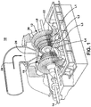
- FIG. 1 shows a perspective partial cut-away illustration of a steam turbine 10.
- Steam turbine 10 includes a rotor 12 that includes a rotating shaft 14 and a plurality of axially spaced rotor wheels 18.
- a plurality of rotating blades 20 are mechanically coupled to each rotor wheel 18. More specifically, blades 20 are arranged in rows that extend circumferentially around each rotor wheel 18.
- a plurality of stationary vanes 22 extends circumferentially around shaft 14, and the vanes are axially positioned between adjacent rows of blades 20. Stationary vanes 22 cooperate with blades 20 to form a stage and to define a portion of a steam flow path through turbine 10.
- steam 24 enters an inlet 26 of turbine 10 and is channeled through stationary vanes 22.
- Vanes 22 direct steam 24 downstream against blades 20. Steam 24 passes through the remaining stages imparting a force on blades 20 causing shaft 14 to rotate. At least one end of turbine 10 may extend axially away from rotor 12 and may be attached to a load or machinery (not shown) such as, but not limited to, a generator, and/or another turbine.
- turbine 10 comprises five stages.
- the five stages are referred to as L0, L1, L2, L3 and L4.
- Stage L4 is the first stage and is the smallest (in a radial direction) of the five stages.
- Stage L3 is the second stage and is the next stage in an axial direction.
- Stage L2 is the third stage and is shown in the middle of the five stages.
- Stage L1 is the fourth and next-to-last stage.
- Stage L0 is the last stage and is the largest (in a radial direction). It is to be understood that five stages are shown as one example only, and a turbine may have more or less than five stages. Also, as will be described herein, the teachings of the invention do not require a multiple stage turbine.
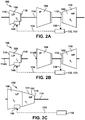
- FIGS. 2A-2C show schematic diagrams of illustrative steam turbines 100 in accordance with an embodiment of the present invention.
- a large steam turbine unit may actually include several turbines that are all co-axially coupled to the same rotating shaft 114.
- one or more turbines may be coupled to different rotating shafts 114A, 114B.
- such a unit may, for example, include a high pressure (HP) turbine 102, an intermediate pressure (IP) turbine 104, and a low pressure (LP) turbine 106. More particularly, as shown in FIG.
- HP high pressure
- IP intermediate pressure
- LP low pressure
- steam turbine 100 may include a first casing 110 including a first (HP) turbine 102 operably coupled to rotating shaft 114 and operable at a first temperature T 1 .
- the first temperature T 1 may be a high temperature that may be, for example, greater than 700 °F (about 370 °C); however, other temperatures may be employed.
- casing 110 includes and an end packing 112 for partially sealing first casing 110 with rotating shaft 114. Similar end packings may be employed for other casings relative to rotating shaft 114 or rotating shaft 114A, 114B ( FIG. 2B ) as the case may be.
- the casings may be made of a material such as stainless steel or steel alloyed with chromium, molybdenum, vanadium, and/or other elements to improve its strength at elevated temperatures. It is understood that the drawings are not to scale and that LP steam turbines may be larger than either HP or IP turbines. In another alternative embodiment, as shown in FIG. 2C , more than one turbine 102, 106 may be positioned within the same casing 111.
- Turbines 102, 104, 106 include similar structure, but operate at different temperatures and pressures.
- a second casing 116 may include second (LP) turbine 106 operably coupled to rotating shaft 114 ( FIG. 2A ) or rotating shaft 114A ( FIG. 2B ) and operable at a second temperature T 2 that is less than first temperature T1.
- the second temperature T 2 may be a relatively low temperature that may range, for example, from about 200 °F (about 90°C) to about 300 °F (about 150 °C); however, other temperatures may be employed.
- Casing 116 also includes an end packing 118 for partially sealing casing 116 with rotating shaft 114 ( FIG. 2A ) or rotating shaft 114A ( FIG. 2B ).
- Casing 116 may be made, for example, from carbon steel having a temperature limit of about 700 °F (about 370 °C).
- Turbine 104 may operate at an intermediate temperature that may range, for example, from about 350 °C to about 600 °C.
- Turbine 104 may also be constructed of high alloy content steel capable of high temperatures (similar to the HP casing).
- a single casing 111 may include first and second (LP) turbines 102, 106 operably coupled to rotating shaft 114 with a single end packing 119.
- Second turbine 106 may be operable at a second temperature T 2 that is less than first temperature T1 of first turbine 102.
- the second temperature T 2 may be a relatively low temperature that may range, for example, from about 200 °F (about 90°C) to about 300 °F (about 150 °C); however, other temperatures may be employed.
- Casing 111 may include material similar to that described above.
- An end packing 112, 118, 119 includes a number of non-contacting seals such as leaf seals, brush seals, labyrinth seals, etc., that partially seal against the rotating shaft of the steam turbine. Due to the finite clearance in these seals there is an inevitable leakage of steam that results in lost potential to produce rotating shaft work. The rate of leakage is dependent upon the seal geometry, clearance, and pressure difference between the steam inside the casing and the air outside the casing.
- steam source 132 is constituted as a steam seal regulator 133.
- Steam seal regulator 133 takes the leakage steam and reduces its pressure to a level suitable to be supplied as seal steam for other end packings.
- steam source 132 may, however, include any now known or later developed source of steam that has a temperature higher than that suitable for second (LP) turbine 106 and a pressure lower than that suitable for second (LP) turbine 106.
- LP second
- LP pressure lower than that suitable for second (LP) turbine 106.
- At least a portion 134 of the flow of steam from steam source 132 is re-directed for introduction into second turbine 106 by an ejector 140 ( FIGS. 3-6 ), 240 ( FIGS. 7-8 ) after mixing with cooler steam from second turbine 106.
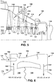
- FIGS. 2A-4 one embodiment of an ejector 140 is illustrated.
- FIG. 3 shows a partial cross-sectional view of second turbine 106
- FIG. 4 shows a schematic cross-sectional view of ejector 140.
- ejector 140 is mounted to an exterior of casing 116 of second turbine 106 to provide as low a pressure drop as possible. Ejector 140 may be mounted farther from second turbine 106, if required. As shown best in FIG.
- ejector 140 forms a mixture 142 of at least a portion 134 of the flow of steam from steam source 132 and a portion of steam 144 removed from an upstream chamber 146 of a given stage (e.g., L0, L1, L2, L3, L4) (LI as shown) of second turbine 106 and introduces mixture 142 into second turbine 106.
- Portion 134 may include the excess flow from steam seal regulator 132 or steam from another source.
- Ejector 140 may include a chamber 150 mounted externally to second casing 116 using any now known or later developed structure.
- Chamber 150 includes openings 152 in fluid communication (via passages, as necessary) with an interior of second casing 116 and steam source 132 ( FIGS. 2A-2C ).
- Ejector 140 includes a diffuser 154 mounted in chamber 150 having an input 156 for receiving at least a portion 134 of the flow of steam from steam source 132 ( FIGS. 2A-C ) and portion 144 of steam removed from the given stage of second turbine 106. While ejector 140 is shown with chamber 150 shaped to form diffuser 154, it is understood that diffuser 154 may be provided as a separate structure.
- Ejector 140 may further include a nozzle 160 mounted in chamber 150 for introducing the at least a portion 134 of the flow of steam from steam source 132 ( FIGS. 2A-2C ) to input 156 of diffuser 154.
- a flow of steam from the nozzle pulls portion 144 of steam from an upstream chamber 146 (i.e., a bowl) of the given stage of the second turbine, forming a fluid pump.
- nozzle 156 may be eliminated and a mechanical pump 166 (shown in phantom)(e.g., a fan or compressor) may be employed for pulling steam portion 144 from upstream chamber 146 of the given stage.
- the hotter steam portion 134 from steam source 132 may have a temperature of, for example, greater than about 700 °F (about 370 °C), and cooler steam portion 144 from second turbine 106 may have a temperature of, for example, about 200 °F (about 90°C) to about 300 °F (about 150 °C).
- mixture 142 forms having a temperature greater than that previously present at the location where the mixture is introduced into second turbine 106.
- ejector 140 mitigates material temperature limitation concerns by mixing the hotter steam portion 134 with cooler steam portion 144 taken from second turbine 106 such that the resulting mixture is nearer to the local temperature of second turbine 106.
- mixture 142 is introduced into upstream chamber 146 of the given stage from which steam portion 144 is taken. That is, mixture 142 is introduced into upstream chamber 146 of the same stage from which steam portion 144 is pulled.
- This embodiment hence, does not require a multiple stage turbine.
- mixture 142 is introduced into a upstream chamber 148 (i.e., bowl) of a preceding, different stage of second turbine 106 than the given stage.
- upstream chamber 148 i.e., bowl
- steam portion 144 may be pulled from upstream chamber 146 of stage L0 and mixture 142 is formed by mixing with higher temperature steam flow 134 and introduced into upstream chamber 148 of preceding, different stage L1.
- second turbine 106 must include a plurality of stages. This embodiment may be useful where less mixing is needed.
- mixture 142 is shown being introduced into an immediately preceding stage, it may be introduced into any one or more preceding stage(s).
- an ejector 240 may be mounted internally to second casing 116.
- Ejector 240 includes similar structure to that described above, except that chamber 150 may not be necessary and insulation 241 (e.g., baffles, bushing) may be required to protect casing 116 from the temperatures of steam portion 134.
- FIG. 7 shows an embodiment in which ejector 240 is positioned within an upstream chamber 246 of a single stage of a turbine.
- FIG. 8 shows another embodiment in which ejector 240 is positioned within an upstream chamber 246 of a given stage and mixture 142 is introduced into an upstream chamber 248 of a preceding, different stage than the given stage.
- a passage 260 may be provided from an output 262 through second casing 116 to the preceding different stage 248 of second turbine 106.
- Ejector 140, 240 may be formed out of any material sufficient to endure the temperature and pressure of the steam communicated therethrough such as stainless steel.
- first turbine 102 supplying the hotter steam portion 134 for mixing with steam portion 144 from a low pressure second turbine 106
- teachings of the invention are not so limited. That is, hotter steam at low pressures from any source may be mixed with steam from any downstream, lower temperature turbine and introduced back into that downstream turbine.
- a method according to embodiments of the invention may include collecting a flow of steam 130 from an end packing 112 of a first casing 110 that encloses a first turbine 102 that operates at a first temperature T 1 or obtaining source of steam 132 from another location providing steam at similar conditions.
- a mixture 142 may be formed of at least a portion 134 of the flow of steam 130 and a portion of steam 144 removed from an upstream chamber 146 of a given stage of a second turbine 106 that operates at a second temperature T 2 that is less than the first temperature T 1 .
- Mixture 142 is introduced into second turbine 106 (either in the same given stage or a preceding stage).
- first,” “second,” and the like, herein do not denote any order, quantity, or importance, but rather are used to distinguish one element from another, and the terms “a” and “an” herein do not denote a limitation of quantity, but rather denote the presence of at least one of the referenced item.
- the modifier “about” used in connection with a quantity is inclusive of the stated value and has the meaning dictated by the context, (e.g., includes the degree of error associated with measurement of the particular quantity).
- suffix "(s)” as used herein is intended to include both the singular and the plural of the term that it modifies, thereby including one or more of that term (e.g., the metal(s) includes one or more metals).
- Ranges disclosed herein are inclusive and independently combinable (e.g., ranges of "up to about 25 wt%, or, more specifically, about 5 wt% to about 20 wt %", is inclusive of the endpoints and all intermediate values of the ranges of "about 5 wt% to about 25 wt%,” etc).
Landscapes
- Engineering & Computer Science (AREA)
- Mechanical Engineering (AREA)
- General Engineering & Computer Science (AREA)
- Turbine Rotor Nozzle Sealing (AREA)
- Jet Pumps And Other Pumps (AREA)
Applications Claiming Priority (1)
| Application Number | Priority Date | Filing Date | Title |
|---|---|---|---|
| US12/482,791 US8221056B2 (en) | 2009-06-11 | 2009-06-11 | Mixing hotter steam with cooler steam for introduction into downstream turbine |
Publications (3)
| Publication Number | Publication Date |
|---|---|
| EP2261460A2 EP2261460A2 (en) | 2010-12-15 |
| EP2261460A3 EP2261460A3 (en) | 2017-12-06 |
| EP2261460B1 true EP2261460B1 (en) | 2020-01-15 |
Family
ID=42281875
Family Applications (1)
| Application Number | Title | Priority Date | Filing Date |
|---|---|---|---|
| EP10165387.1A Active EP2261460B1 (en) | 2009-06-11 | 2010-06-09 | Steam turbine and apparatus for mixing hotter steam with cooler steam for introduction into downstream turbine |
Country Status (4)
| Country | Link |
|---|---|
| US (1) | US8221056B2 (enExample) |
| EP (1) | EP2261460B1 (enExample) |
| JP (1) | JP5523940B2 (enExample) |
| RU (1) | RU2527802C2 (enExample) |
Families Citing this family (7)
| Publication number | Priority date | Publication date | Assignee | Title |
|---|---|---|---|---|
| US20110030335A1 (en) * | 2009-08-06 | 2011-02-10 | General Electric Company | Combined-cycle steam turbine and system having novel cooling flow configuration |
| US8689557B2 (en) * | 2011-02-04 | 2014-04-08 | General Electric Company | Steam seal dump re-entry system |
| US9297277B2 (en) * | 2011-09-30 | 2016-03-29 | General Electric Company | Power plant |
| US20130156540A1 (en) * | 2011-12-14 | 2013-06-20 | Santhosh Donkada | Steam seal header, method of using a steam seal header and steam turbine system incorporating a steam seal header |
| US9540942B2 (en) * | 2012-04-13 | 2017-01-10 | General Electric Company | Shaft sealing system for steam turbines |
| EP3358142B1 (en) | 2017-02-02 | 2021-08-18 | General Electric Company | Turbine tip shroud leakage flow control |
| JP7039795B2 (ja) | 2018-02-23 | 2022-03-23 | 三菱重工業株式会社 | 粉体供給ホッパ加圧装置、ガス化炉設備およびガス化複合発電設備ならびに粉体供給ホッパ加圧装置の制御方法 |
Family Cites Families (20)
| Publication number | Priority date | Publication date | Assignee | Title |
|---|---|---|---|---|
| US3972196A (en) * | 1974-05-10 | 1976-08-03 | Westinghouse Electric Corporation | Steam pressure increasing device for drive turbines |
| CS206477B1 (en) * | 1979-02-12 | 1981-06-30 | Zdenek Roth | Gas exhausting apparatus |
| JPS55125301A (en) * | 1979-03-19 | 1980-09-27 | Toshiba Corp | Steam turbine |
| JPS56115801A (en) * | 1980-02-20 | 1981-09-11 | Hitachi Ltd | Cooling mechanism for rotary shaft |
| US4576008A (en) * | 1984-01-11 | 1986-03-18 | Westinghouse Electric Corp. | Turbine protection system for bypass operation |
| EP0577908B1 (en) * | 1992-07-10 | 1995-09-06 | Ansaldo Energia S.P.A. | A process for sealing the rotor of a turbine which uses wet geothermal steam |
| JPH0941905A (ja) * | 1995-08-01 | 1997-02-10 | Mitsubishi Heavy Ind Ltd | グランド蒸気処理装置 |
| DE19701020A1 (de) * | 1997-01-14 | 1998-07-23 | Siemens Ag | Dampfturbine |
| US6443690B1 (en) * | 1999-05-05 | 2002-09-03 | Siemens Westinghouse Power Corporation | Steam cooling system for balance piston of a steam turbine and associated methods |
| DE50009046D1 (de) * | 1999-08-27 | 2005-01-27 | Siemens Ag | Turbine sowie verfahren zur abführung von leckfluid |
| RU2174606C2 (ru) * | 1999-11-24 | 2001-10-10 | Акционерное общество открытого типа "Ленинградский Металлический завод" | Узел концевого уплотнения цилиндра паровой турбины |
| US6412270B1 (en) * | 2001-09-12 | 2002-07-02 | General Electric Company | Apparatus and methods for flowing a cooling or purge medium in a turbine downstream of a turbine seal |
| US6644012B2 (en) * | 2001-11-02 | 2003-11-11 | Alston (Switzerland) Ltd | Gas turbine set |
| US7488153B2 (en) * | 2002-07-01 | 2009-02-10 | Alstom Technology Ltd. | Steam turbine |
| US6782703B2 (en) * | 2002-09-11 | 2004-08-31 | Siemens Westinghouse Power Corporation | Apparatus for starting a combined cycle power plant |
| WO2004090291A1 (de) * | 2003-04-07 | 2004-10-21 | Alstom Technology Ltd | Turbomaschine |
| WO2005050768A1 (en) * | 2003-11-19 | 2005-06-02 | Questair Technologies Inc. | High efficiency load-following solid oxide fuel cell systems |
| ITTO20050281A1 (it) * | 2005-04-27 | 2006-10-28 | Ansaldo Energia Spa | Impianto a turbina provvisto di un prelievo di vapore e di un sistema per raffreddare una sezione di turbina disposta a valle di tale prelievo |
| US7823390B2 (en) * | 2007-02-27 | 2010-11-02 | General Electric Company | Mixer for cooling and sealing air system of turbomachinery |
| RU110413U1 (ru) * | 2011-08-05 | 2011-11-20 | Вадим Витальевич Выгулярный | Турбоустановка для генератора переменного тока |
-
2009
- 2009-06-11 US US12/482,791 patent/US8221056B2/en not_active Expired - Fee Related
-
2010
- 2010-06-09 EP EP10165387.1A patent/EP2261460B1/en active Active
- 2010-06-10 RU RU2010123477/06A patent/RU2527802C2/ru not_active IP Right Cessation
- 2010-06-11 JP JP2010133457A patent/JP5523940B2/ja not_active Expired - Fee Related
Non-Patent Citations (1)
| Title |
|---|
| None * |
Also Published As
| Publication number | Publication date |
|---|---|
| RU2010123477A (ru) | 2011-12-20 |
| EP2261460A3 (en) | 2017-12-06 |
| RU2527802C2 (ru) | 2014-09-10 |
| US20100316488A1 (en) | 2010-12-16 |
| JP2010285990A (ja) | 2010-12-24 |
| US8221056B2 (en) | 2012-07-17 |
| JP5523940B2 (ja) | 2014-06-18 |
| EP2261460A2 (en) | 2010-12-15 |
Similar Documents
| Publication | Publication Date | Title |
|---|---|---|
| EP2261460B1 (en) | Steam turbine and apparatus for mixing hotter steam with cooler steam for introduction into downstream turbine | |
| CN102032046B (zh) | 用于燃气涡轮机的冷却系统和对应的操作方法 | |
| US3382670A (en) | Gas turbine engine lubrication system | |
| US10794469B2 (en) | Geared gas turbine engine | |
| CN110805617B (zh) | 流体支承件组件 | |
| US6910852B2 (en) | Methods and apparatus for cooling gas turbine engine rotor assemblies | |
| EP2653659B1 (en) | Cooling assembly for a gas turbine system | |
| US20070189890A1 (en) | Gas turbine engine rotor ventilation arrangement | |
| EP3808963B1 (en) | Gas turbine engine | |
| CN109477389B (zh) | 用于涡轮中的机内排出回路的密封件的系统和方法 | |
| US8147185B2 (en) | Systems, methods, and apparatus for controlling gas leakage in a turbine | |
| US9169737B2 (en) | Gas turbine engine rotor seal | |
| EP3388636B1 (en) | Vented buffer air supply for intershaft seals | |
| CN101094971A (zh) | 涡轮机装置的优化的涡轮机级以及设计方法 | |
| US10436030B2 (en) | Steam turbine and method for operating a steam turbine | |
| CN109812340B (zh) | 包括外部冷却系统的燃气轮机及其冷却方法 | |
| US6431756B2 (en) | Bearing damper | |
| US20110097198A1 (en) | Turbo machine efficiency equalizer system | |
| EP2518277A1 (en) | Cooling method and device in single-flow turbine | |
| EP4174286A1 (en) | Gas turbine assembly for power plant with improved rotor and turbine blades cooling and method for operating this gas turbine assembly | |
| US7156613B2 (en) | Arrangement for bearing relief in a gas turbine | |
| US12196132B1 (en) | System and method for preloading a bearing | |
| US11933295B2 (en) | Tapered shafts for fluid pumps | |
| US3724969A (en) | Turbine construction | |
| US11346558B2 (en) | Fuel injector |
Legal Events
| Date | Code | Title | Description |
|---|---|---|---|
| PUAI | Public reference made under article 153(3) epc to a published international application that has entered the european phase |
Free format text: ORIGINAL CODE: 0009012 |
|
| AK | Designated contracting states |
Kind code of ref document: A2 Designated state(s): AL AT BE BG CH CY CZ DE DK EE ES FI FR GB GR HR HU IE IS IT LI LT LU LV MC MK MT NL NO PL PT RO SE SI SK SM TR |
|
| AX | Request for extension of the european patent |
Extension state: BA ME RS |
|
| REG | Reference to a national code |
Ref country code: DE Ref legal event code: R079 Ref document number: 602010062777 Country of ref document: DE Free format text: PREVIOUS MAIN CLASS: F01D0001000000 Ipc: F01D0025120000 |
|
| PUAL | Search report despatched |
Free format text: ORIGINAL CODE: 0009013 |
|
| AK | Designated contracting states |
Kind code of ref document: A3 Designated state(s): AL AT BE BG CH CY CZ DE DK EE ES FI FR GB GR HR HU IE IS IT LI LT LU LV MC MK MT NL NO PL PT RO SE SI SK SM TR |
|
| AX | Request for extension of the european patent |
Extension state: BA ME RS |
|
| RIC1 | Information provided on ipc code assigned before grant |
Ipc: F01D 25/12 20060101AFI20171102BHEP Ipc: F01D 1/00 20060101ALI20171102BHEP |
|
| STAA | Information on the status of an ep patent application or granted ep patent |
Free format text: STATUS: REQUEST FOR EXAMINATION WAS MADE |
|
| 17P | Request for examination filed |
Effective date: 20180606 |
|
| RBV | Designated contracting states (corrected) |
Designated state(s): AL AT BE BG CH CY CZ DE DK EE ES FI FR GB GR HR HU IE IS IT LI LT LU LV MC MK MT NL NO PL PT RO SE SI SK SM TR |
|
| STAA | Information on the status of an ep patent application or granted ep patent |
Free format text: STATUS: EXAMINATION IS IN PROGRESS |
|
| 17Q | First examination report despatched |
Effective date: 20180720 |
|
| GRAP | Despatch of communication of intention to grant a patent |
Free format text: ORIGINAL CODE: EPIDOSNIGR1 |
|
| STAA | Information on the status of an ep patent application or granted ep patent |
Free format text: STATUS: GRANT OF PATENT IS INTENDED |
|
| INTG | Intention to grant announced |
Effective date: 20190418 |
|
| GRAS | Grant fee paid |
Free format text: ORIGINAL CODE: EPIDOSNIGR3 |
|
| GRAA | (expected) grant |
Free format text: ORIGINAL CODE: 0009210 |
|
| STAA | Information on the status of an ep patent application or granted ep patent |
Free format text: STATUS: THE PATENT HAS BEEN GRANTED |
|
| AK | Designated contracting states |
Kind code of ref document: B1 Designated state(s): AL AT BE BG CH CY CZ DE DK EE ES FI FR GB GR HR HU IE IS IT LI LT LU LV MC MK MT NL NO PL PT RO SE SI SK SM TR |
|
| REG | Reference to a national code |
Ref country code: CH Ref legal event code: EP Ref country code: GB Ref legal event code: FG4D |
|
| REG | Reference to a national code |
Ref country code: IE Ref legal event code: FG4D |
|
| REG | Reference to a national code |
Ref country code: DE Ref legal event code: R096 Ref document number: 602010062777 Country of ref document: DE |
|
| REG | Reference to a national code |
Ref country code: AT Ref legal event code: REF Ref document number: 1225325 Country of ref document: AT Kind code of ref document: T Effective date: 20200215 |
|
| REG | Reference to a national code |
Ref country code: NL Ref legal event code: MP Effective date: 20200115 |
|
| REG | Reference to a national code |
Ref country code: LT Ref legal event code: MG4D |
|
| PG25 | Lapsed in a contracting state [announced via postgrant information from national office to epo] |
Ref country code: NO Free format text: LAPSE BECAUSE OF FAILURE TO SUBMIT A TRANSLATION OF THE DESCRIPTION OR TO PAY THE FEE WITHIN THE PRESCRIBED TIME-LIMIT Effective date: 20200415 Ref country code: NL Free format text: LAPSE BECAUSE OF FAILURE TO SUBMIT A TRANSLATION OF THE DESCRIPTION OR TO PAY THE FEE WITHIN THE PRESCRIBED TIME-LIMIT Effective date: 20200115 Ref country code: PT Free format text: LAPSE BECAUSE OF FAILURE TO SUBMIT A TRANSLATION OF THE DESCRIPTION OR TO PAY THE FEE WITHIN THE PRESCRIBED TIME-LIMIT Effective date: 20200607 Ref country code: FI Free format text: LAPSE BECAUSE OF FAILURE TO SUBMIT A TRANSLATION OF THE DESCRIPTION OR TO PAY THE FEE WITHIN THE PRESCRIBED TIME-LIMIT Effective date: 20200115 |
|
| PG25 | Lapsed in a contracting state [announced via postgrant information from national office to epo] |
Ref country code: IS Free format text: LAPSE BECAUSE OF FAILURE TO SUBMIT A TRANSLATION OF THE DESCRIPTION OR TO PAY THE FEE WITHIN THE PRESCRIBED TIME-LIMIT Effective date: 20200515 Ref country code: GR Free format text: LAPSE BECAUSE OF FAILURE TO SUBMIT A TRANSLATION OF THE DESCRIPTION OR TO PAY THE FEE WITHIN THE PRESCRIBED TIME-LIMIT Effective date: 20200416 Ref country code: HR Free format text: LAPSE BECAUSE OF FAILURE TO SUBMIT A TRANSLATION OF THE DESCRIPTION OR TO PAY THE FEE WITHIN THE PRESCRIBED TIME-LIMIT Effective date: 20200115 Ref country code: LV Free format text: LAPSE BECAUSE OF FAILURE TO SUBMIT A TRANSLATION OF THE DESCRIPTION OR TO PAY THE FEE WITHIN THE PRESCRIBED TIME-LIMIT Effective date: 20200115 Ref country code: SE Free format text: LAPSE BECAUSE OF FAILURE TO SUBMIT A TRANSLATION OF THE DESCRIPTION OR TO PAY THE FEE WITHIN THE PRESCRIBED TIME-LIMIT Effective date: 20200115 Ref country code: BG Free format text: LAPSE BECAUSE OF FAILURE TO SUBMIT A TRANSLATION OF THE DESCRIPTION OR TO PAY THE FEE WITHIN THE PRESCRIBED TIME-LIMIT Effective date: 20200415 |
|
| REG | Reference to a national code |
Ref country code: DE Ref legal event code: R097 Ref document number: 602010062777 Country of ref document: DE |
|
| PG25 | Lapsed in a contracting state [announced via postgrant information from national office to epo] |
Ref country code: ES Free format text: LAPSE BECAUSE OF FAILURE TO SUBMIT A TRANSLATION OF THE DESCRIPTION OR TO PAY THE FEE WITHIN THE PRESCRIBED TIME-LIMIT Effective date: 20200115 Ref country code: DK Free format text: LAPSE BECAUSE OF FAILURE TO SUBMIT A TRANSLATION OF THE DESCRIPTION OR TO PAY THE FEE WITHIN THE PRESCRIBED TIME-LIMIT Effective date: 20200115 Ref country code: EE Free format text: LAPSE BECAUSE OF FAILURE TO SUBMIT A TRANSLATION OF THE DESCRIPTION OR TO PAY THE FEE WITHIN THE PRESCRIBED TIME-LIMIT Effective date: 20200115 Ref country code: LT Free format text: LAPSE BECAUSE OF FAILURE TO SUBMIT A TRANSLATION OF THE DESCRIPTION OR TO PAY THE FEE WITHIN THE PRESCRIBED TIME-LIMIT Effective date: 20200115 Ref country code: CZ Free format text: LAPSE BECAUSE OF FAILURE TO SUBMIT A TRANSLATION OF THE DESCRIPTION OR TO PAY THE FEE WITHIN THE PRESCRIBED TIME-LIMIT Effective date: 20200115 Ref country code: RO Free format text: LAPSE BECAUSE OF FAILURE TO SUBMIT A TRANSLATION OF THE DESCRIPTION OR TO PAY THE FEE WITHIN THE PRESCRIBED TIME-LIMIT Effective date: 20200115 Ref country code: SK Free format text: LAPSE BECAUSE OF FAILURE TO SUBMIT A TRANSLATION OF THE DESCRIPTION OR TO PAY THE FEE WITHIN THE PRESCRIBED TIME-LIMIT Effective date: 20200115 Ref country code: SM Free format text: LAPSE BECAUSE OF FAILURE TO SUBMIT A TRANSLATION OF THE DESCRIPTION OR TO PAY THE FEE WITHIN THE PRESCRIBED TIME-LIMIT Effective date: 20200115 |
|
| REG | Reference to a national code |
Ref country code: AT Ref legal event code: MK05 Ref document number: 1225325 Country of ref document: AT Kind code of ref document: T Effective date: 20200115 |
|
| PLBE | No opposition filed within time limit |
Free format text: ORIGINAL CODE: 0009261 |
|
| STAA | Information on the status of an ep patent application or granted ep patent |
Free format text: STATUS: NO OPPOSITION FILED WITHIN TIME LIMIT |
|
| 26N | No opposition filed |
Effective date: 20201016 |
|
| PG25 | Lapsed in a contracting state [announced via postgrant information from national office to epo] |
Ref country code: IT Free format text: LAPSE BECAUSE OF FAILURE TO SUBMIT A TRANSLATION OF THE DESCRIPTION OR TO PAY THE FEE WITHIN THE PRESCRIBED TIME-LIMIT Effective date: 20200115 Ref country code: MC Free format text: LAPSE BECAUSE OF FAILURE TO SUBMIT A TRANSLATION OF THE DESCRIPTION OR TO PAY THE FEE WITHIN THE PRESCRIBED TIME-LIMIT Effective date: 20200115 Ref country code: AT Free format text: LAPSE BECAUSE OF FAILURE TO SUBMIT A TRANSLATION OF THE DESCRIPTION OR TO PAY THE FEE WITHIN THE PRESCRIBED TIME-LIMIT Effective date: 20200115 |
|
| REG | Reference to a national code |
Ref country code: CH Ref legal event code: PL |
|
| PG25 | Lapsed in a contracting state [announced via postgrant information from national office to epo] |
Ref country code: SI Free format text: LAPSE BECAUSE OF FAILURE TO SUBMIT A TRANSLATION OF THE DESCRIPTION OR TO PAY THE FEE WITHIN THE PRESCRIBED TIME-LIMIT Effective date: 20200115 Ref country code: PL Free format text: LAPSE BECAUSE OF FAILURE TO SUBMIT A TRANSLATION OF THE DESCRIPTION OR TO PAY THE FEE WITHIN THE PRESCRIBED TIME-LIMIT Effective date: 20200115 |
|
| GBPC | Gb: european patent ceased through non-payment of renewal fee |
Effective date: 20200609 |
|
| PG25 | Lapsed in a contracting state [announced via postgrant information from national office to epo] |
Ref country code: LU Free format text: LAPSE BECAUSE OF NON-PAYMENT OF DUE FEES Effective date: 20200609 |
|
| REG | Reference to a national code |
Ref country code: BE Ref legal event code: MM Effective date: 20200630 |
|
| PG25 | Lapsed in a contracting state [announced via postgrant information from national office to epo] |
Ref country code: CH Free format text: LAPSE BECAUSE OF NON-PAYMENT OF DUE FEES Effective date: 20200630 Ref country code: LI Free format text: LAPSE BECAUSE OF NON-PAYMENT OF DUE FEES Effective date: 20200630 Ref country code: IE Free format text: LAPSE BECAUSE OF NON-PAYMENT OF DUE FEES Effective date: 20200609 Ref country code: GB Free format text: LAPSE BECAUSE OF NON-PAYMENT OF DUE FEES Effective date: 20200609 Ref country code: FR Free format text: LAPSE BECAUSE OF NON-PAYMENT OF DUE FEES Effective date: 20200630 |
|
| PG25 | Lapsed in a contracting state [announced via postgrant information from national office to epo] |
Ref country code: BE Free format text: LAPSE BECAUSE OF NON-PAYMENT OF DUE FEES Effective date: 20200630 |
|
| PGFP | Annual fee paid to national office [announced via postgrant information from national office to epo] |
Ref country code: DE Payment date: 20210519 Year of fee payment: 12 |
|
| PG25 | Lapsed in a contracting state [announced via postgrant information from national office to epo] |
Ref country code: TR Free format text: LAPSE BECAUSE OF FAILURE TO SUBMIT A TRANSLATION OF THE DESCRIPTION OR TO PAY THE FEE WITHIN THE PRESCRIBED TIME-LIMIT Effective date: 20200115 Ref country code: MT Free format text: LAPSE BECAUSE OF FAILURE TO SUBMIT A TRANSLATION OF THE DESCRIPTION OR TO PAY THE FEE WITHIN THE PRESCRIBED TIME-LIMIT Effective date: 20200115 Ref country code: CY Free format text: LAPSE BECAUSE OF FAILURE TO SUBMIT A TRANSLATION OF THE DESCRIPTION OR TO PAY THE FEE WITHIN THE PRESCRIBED TIME-LIMIT Effective date: 20200115 |
|
| PG25 | Lapsed in a contracting state [announced via postgrant information from national office to epo] |
Ref country code: MK Free format text: LAPSE BECAUSE OF FAILURE TO SUBMIT A TRANSLATION OF THE DESCRIPTION OR TO PAY THE FEE WITHIN THE PRESCRIBED TIME-LIMIT Effective date: 20200115 Ref country code: AL Free format text: LAPSE BECAUSE OF FAILURE TO SUBMIT A TRANSLATION OF THE DESCRIPTION OR TO PAY THE FEE WITHIN THE PRESCRIBED TIME-LIMIT Effective date: 20200115 |
|
| REG | Reference to a national code |
Ref country code: DE Ref legal event code: R119 Ref document number: 602010062777 Country of ref document: DE |
|
| PG25 | Lapsed in a contracting state [announced via postgrant information from national office to epo] |
Ref country code: DE Free format text: LAPSE BECAUSE OF NON-PAYMENT OF DUE FEES Effective date: 20230103 |