EP2260960A1 - Schneideeinsatz für einen bohrer, bohrer und schneideverfahren damit - Google Patents
Schneideeinsatz für einen bohrer, bohrer und schneideverfahren damit Download PDFInfo
- Publication number
- EP2260960A1 EP2260960A1 EP09714448A EP09714448A EP2260960A1 EP 2260960 A1 EP2260960 A1 EP 2260960A1 EP 09714448 A EP09714448 A EP 09714448A EP 09714448 A EP09714448 A EP 09714448A EP 2260960 A1 EP2260960 A1 EP 2260960A1
- Authority
- EP
- European Patent Office
- Prior art keywords
- region
- face
- cutting
- insert
- drill
- Prior art date
- Legal status (The legal status is an assumption and is not a legal conclusion. Google has not performed a legal analysis and makes no representation as to the accuracy of the status listed.)
- Granted
Links
- 238000000034 method Methods 0.000 title claims abstract description 11
- 230000002093 peripheral effect Effects 0.000 claims description 16
- 238000003754 machining Methods 0.000 description 15
- 238000010276 construction Methods 0.000 description 8
- 230000001965 increasing effect Effects 0.000 description 5
- 230000000694 effects Effects 0.000 description 4
- 230000002708 enhancing effect Effects 0.000 description 3
- 238000005553 drilling Methods 0.000 description 2
- 230000001154 acute effect Effects 0.000 description 1
- 230000001747 exhibiting effect Effects 0.000 description 1
- 230000001788 irregular Effects 0.000 description 1
Images


Classifications
-
- B—PERFORMING OPERATIONS; TRANSPORTING
- B23—MACHINE TOOLS; METAL-WORKING NOT OTHERWISE PROVIDED FOR
- B23B—TURNING; BORING
- B23B27/00—Tools for turning or boring machines; Tools of a similar kind in general; Accessories therefor
- B23B27/14—Cutting tools of which the bits or tips or cutting inserts are of special material
- B23B27/141—Specially shaped plate-like cutting inserts, i.e. length greater or equal to width, width greater than or equal to thickness
-
- B—PERFORMING OPERATIONS; TRANSPORTING
- B23—MACHINE TOOLS; METAL-WORKING NOT OTHERWISE PROVIDED FOR
- B23B—TURNING; BORING
- B23B51/00—Tools for drilling machines
-
- B—PERFORMING OPERATIONS; TRANSPORTING
- B23—MACHINE TOOLS; METAL-WORKING NOT OTHERWISE PROVIDED FOR
- B23B—TURNING; BORING
- B23B2200/00—Details of cutting inserts
- B23B2200/08—Rake or top surfaces
-
- B—PERFORMING OPERATIONS; TRANSPORTING
- B23—MACHINE TOOLS; METAL-WORKING NOT OTHERWISE PROVIDED FOR
- B23B—TURNING; BORING
- B23B2200/00—Details of cutting inserts
- B23B2200/08—Rake or top surfaces
- B23B2200/086—Rake or top surfaces with one or more grooves
- B23B2200/087—Rake or top surfaces with one or more grooves for chip breaking
-
- B—PERFORMING OPERATIONS; TRANSPORTING
- B23—MACHINE TOOLS; METAL-WORKING NOT OTHERWISE PROVIDED FOR
- B23B—TURNING; BORING
- B23B2200/00—Details of cutting inserts
- B23B2200/12—Side or flank surfaces
- B23B2200/125—Side or flank surfaces discontinuous
-
- B—PERFORMING OPERATIONS; TRANSPORTING
- B23—MACHINE TOOLS; METAL-WORKING NOT OTHERWISE PROVIDED FOR
- B23B—TURNING; BORING
- B23B2205/00—Fixation of cutting inserts in holders
- B23B2205/12—Seats for cutting inserts
-
- B—PERFORMING OPERATIONS; TRANSPORTING
- B23—MACHINE TOOLS; METAL-WORKING NOT OTHERWISE PROVIDED FOR
- B23B—TURNING; BORING
- B23B2251/00—Details of tools for drilling machines
- B23B2251/50—Drilling tools comprising cutting inserts
-
- Y—GENERAL TAGGING OF NEW TECHNOLOGICAL DEVELOPMENTS; GENERAL TAGGING OF CROSS-SECTIONAL TECHNOLOGIES SPANNING OVER SEVERAL SECTIONS OF THE IPC; TECHNICAL SUBJECTS COVERED BY FORMER USPC CROSS-REFERENCE ART COLLECTIONS [XRACs] AND DIGESTS
- Y10—TECHNICAL SUBJECTS COVERED BY FORMER USPC
- Y10T—TECHNICAL SUBJECTS COVERED BY FORMER US CLASSIFICATION
- Y10T407/00—Cutters, for shaping
- Y10T407/19—Rotary cutting tool
- Y10T407/1906—Rotary cutting tool including holder [i.e., head] having seat for inserted tool
- Y10T407/1908—Face or end mill
-
- Y—GENERAL TAGGING OF NEW TECHNOLOGICAL DEVELOPMENTS; GENERAL TAGGING OF CROSS-SECTIONAL TECHNOLOGIES SPANNING OVER SEVERAL SECTIONS OF THE IPC; TECHNICAL SUBJECTS COVERED BY FORMER USPC CROSS-REFERENCE ART COLLECTIONS [XRACs] AND DIGESTS
- Y10—TECHNICAL SUBJECTS COVERED BY FORMER USPC
- Y10T—TECHNICAL SUBJECTS COVERED BY FORMER US CLASSIFICATION
- Y10T407/00—Cutters, for shaping
- Y10T407/19—Rotary cutting tool
- Y10T407/1946—Face or end mill
-
- Y—GENERAL TAGGING OF NEW TECHNOLOGICAL DEVELOPMENTS; GENERAL TAGGING OF CROSS-SECTIONAL TECHNOLOGIES SPANNING OVER SEVERAL SECTIONS OF THE IPC; TECHNICAL SUBJECTS COVERED BY FORMER USPC CROSS-REFERENCE ART COLLECTIONS [XRACs] AND DIGESTS
- Y10—TECHNICAL SUBJECTS COVERED BY FORMER USPC
- Y10T—TECHNICAL SUBJECTS COVERED BY FORMER US CLASSIFICATION
- Y10T407/00—Cutters, for shaping
- Y10T407/23—Cutters, for shaping including tool having plural alternatively usable cutting edges
-
- Y—GENERAL TAGGING OF NEW TECHNOLOGICAL DEVELOPMENTS; GENERAL TAGGING OF CROSS-SECTIONAL TECHNOLOGIES SPANNING OVER SEVERAL SECTIONS OF THE IPC; TECHNICAL SUBJECTS COVERED BY FORMER USPC CROSS-REFERENCE ART COLLECTIONS [XRACs] AND DIGESTS
- Y10—TECHNICAL SUBJECTS COVERED BY FORMER USPC
- Y10T—TECHNICAL SUBJECTS COVERED BY FORMER US CLASSIFICATION
- Y10T408/00—Cutting by use of rotating axially moving tool
- Y10T408/03—Processes
-
- Y—GENERAL TAGGING OF NEW TECHNOLOGICAL DEVELOPMENTS; GENERAL TAGGING OF CROSS-SECTIONAL TECHNOLOGIES SPANNING OVER SEVERAL SECTIONS OF THE IPC; TECHNICAL SUBJECTS COVERED BY FORMER USPC CROSS-REFERENCE ART COLLECTIONS [XRACs] AND DIGESTS
- Y10—TECHNICAL SUBJECTS COVERED BY FORMER USPC
- Y10T—TECHNICAL SUBJECTS COVERED BY FORMER US CLASSIFICATION
- Y10T408/00—Cutting by use of rotating axially moving tool
- Y10T408/89—Tool or Tool with support
- Y10T408/909—Having peripherally spaced cutting edges
- Y10T408/9098—Having peripherally spaced cutting edges with means to retain Tool to support
-
- Y—GENERAL TAGGING OF NEW TECHNOLOGICAL DEVELOPMENTS; GENERAL TAGGING OF CROSS-SECTIONAL TECHNOLOGIES SPANNING OVER SEVERAL SECTIONS OF THE IPC; TECHNICAL SUBJECTS COVERED BY FORMER USPC CROSS-REFERENCE ART COLLECTIONS [XRACs] AND DIGESTS
- Y10—TECHNICAL SUBJECTS COVERED BY FORMER USPC
- Y10T—TECHNICAL SUBJECTS COVERED BY FORMER US CLASSIFICATION
- Y10T408/00—Cutting by use of rotating axially moving tool
- Y10T408/94—Tool-support
Definitions
- the present invention relates to a cutting insert for a drill and a drill which are used by being attached to a holder, and a method of cutting using the same.
- a drill for drilling holes there are for example those in which an inner insert and an outer insert are detachably attached to the tip end of a holder so that their respective rotation loci cross each other.
- those in which the inner insert and the outer insert have the same shape are frequently used from the viewpoint of excellent economic performance. That is, the drills in which a plurality of cutting inserts for a drill of similar type (hereinafter referred to as "insert" in some cases) are respectively detachably attached to the inner side and the outer side at the tip end of the holder are frequently used.
- the inserts used for this type of drill include an inner cutting edge and an outer cutting edge.
- the inner cutting edge is the cutting edge for mainly cutting (machining) an inner portion of a bottom face of a hole when it is used as the inner insert.
- the outer cutting edge is the cutting edge for mainly cutting an outer portion of a bottom face of a hole when it is used as the outer insert.
- the inner cutting edge and the outer cutting edge are formed at the intersection between the upper face and the side face.
- a clearance angle for avoiding interference with a work material is provided on each of the side faces corresponding to these cutting edges.
- a corner portion located between both of these cutting edges is formed in a round shape.
- the same clearance angle as that on the side faces corresponding to these cutting edges is provided on the side face corresponding to the corner portion (refer to Fig. 6(b) in the above publication).
- the holder used for this type of drill has, at its tip end, an inner peripheral insert pocket for attaching the inner insert, and an outer peripheral insert pocket for attaching the outer insert (refer to, for example, the above publication).
- the outer peripheral insert pocket is openedly formed at the outer periphery of the holder.
- the inner peripheral insert pocket has a wall face which is located toward the outer periphery of the holder and opposed to the side face of the inner insert.
- An outer wall exists between the wall face and the outer peripheral face of the holder (refer to Figs. 2 and 3 of the above publication).
- the thickness of the outer wall becomes minimum between the wall face opposed to the side face of the corner portion located on the side not to be involved in cutting in the insert, and the outer peripheral face of the holder. Therefore, there has been the problem that the strength of the portion of the holder where the thickness of the outer wall becomes minimum is deteriorated, and the holder is susceptible to breakage during machining.
- the outer wall does not exist in the outer peripheral insert pocket formed openedly in the outer periphery, and the portion of the holder where the outer peripheral insert pocket is formed has low strength. Hence, there has also been the problem that the holder is liable to be broken from the portion of the holder during machining.
- An object of the present invention is to provide a cutting insert for a drill and a drill which are used by being attached to a holder and capable of reducing breakage of the holder during machining, as well as a method of cutting using the same.
- a cutting insert for a drill comprises an upper face having a first corner portion, and a first side and a second side respectively disposed on both sides of the first corner portion, a bottom face corresponding to the upper face; and a side face located between the upper face and the bottom face.
- the cutting insert for the drill has a first cutting edge formed along the first side, and a second cutting edge formed along the second side.
- the side face has a first region corresponding to the first cutting edge, a second region corresponding to the second cutting edge, and a third region corresponding to the first corner portion.
- the third region has an upper region which is adjacent to the first corner portion and disposed toward the upper face, and a lower region located below the upper region.
- An inclination angle ⁇ 3 of the lower region to the bottom face is larger than each of an inclination angle ⁇ 1 of the first region to the bottom face and an inclination angle ⁇ 2 of the second region to the bottom face.
- a cutting insert for a drill comprises an upper face having a substantially square shape when viewed from above, and having a pair of first corner portions located on one diagonal; a first side and a second side respectively disposed on both sides of each of the first corner portions; and a pair of second corner portions which are disposed between the first side and the second side disposed correspondingly to the first corner portions different from each other, and which are located on the other diagonal; a bottom face corresponding to the upper face; and a side face located between the upper face and the bottom face.
- the cutting insert for the drill has a first cutting edge formed along the first side; and a second cutting edge formed along the second side.
- the side face has a first region corresponding to the first cutting edge, a second region corresponding to the second cutting edge, a third region corresponding to the first corner portion, and a fourth region corresponding to the second corner portion.
- Each of the third region and the fourth region has an upper region which is adjacent to the first corner portion and the second corner portion and disposed toward the upper face, and a lower region located below the upper region.
- Each of an inclination angle ⁇ 3 of the lower region in the third region to the bottom face and an inclination angle ⁇ 5 of the lower region in the fourth region to the bottom face is larger than each of an inclination angle ⁇ 1 of the first region to the bottom face and an inclination angle ⁇ 2 of the second region to the bottom face.
- a drill according to an embodiment of the present invention comprises a holder comprising a first insert pocket formed at a tip end portion, and a second insert pocket formed at a tip end portion toward the outer periphery than the first insert pocket; and a pair of the cutting insert for a drill each having at least two pieces of the first corner portions.
- one of the paired cutting inserts for the drill is attached to the first insert pocket so that at least a part of the first cutting edge protrudes from the tip end of the holder, and the other is attached to the second insert pocket so that at least a part of the second cutting edge protrudes from the tip end of the holder.
- At least one of the paired cutting inserts for the drill is attached to the insert pocket so that the first corner portion of the two first corner portions which is located on a side not to be involved in cutting in the cutting insert for the drill is disposed toward the outer periphery of the holder in the insert pocket with the cutting insert for the drill attached thereto, and disposed toward the basal end of the holder.
- a drill according to other embodiment of the present invention comprises a holder comprising a first insert pocket formed at a tip end portion, and a second insert pocket formed at a tip end portion toward the outer periphery than the first insert pocket; and a pair of cutting inserts for a drill.
- Each of the paired cutting inserts for the drill comprises an upper face having at least two corner portions, and a first side and a second side respectively disposed on both sides of each corner portion; a bottom face corresponding to the upper face; a side face located between the upper face and the bottom face; a first cutting edge formed along the first side; and a second cutting edge formed along the second side.
- the side face has a first region corresponding to the first cutting edge, a second region corresponding to the second cutting edge, and a third region corresponding to the corner portion.
- the third region has an upper region which is adjacent to the corner portion and disposed toward the upper face, and a lower region located below the upper region.
- An inclination angle ⁇ 3 of the lower region to the bottom face is larger than each of an inclination angle ⁇ 1 of the first region to the bottom face and an inclination angle ⁇ 2 of the second region to the bottom face.
- At least one of the paired cutting inserts for the drill is attached to the first insert pocket so that at least a part of the first cutting edge protrudes from the tip end of the holder, and the other is attached to the second insert pocket so that at least a part of the second cutting edge protrudes from the tip end of the holder.
- At least one of the paired cutting inserts for the drill is attached to the insert pocket so that the corner portion of the two corner portions which is located on a side not to be involved in cutting in the cutting insert for the drill is disposed toward the outer periphery of the holder in the insert pocket with the cutting insert for the drill attached thereto, and disposed toward the basal end of the holder.
- a holder comprises a first insert pocket formed at a tip end portion, and a second insert pocket formed at a tip end portion toward the outer periphery than the first insert pocket.
- Each of the first insert pocket and the second insert pocket comprises a constraining seat face contacting against the bottom face of a cutting insert for a drill, and a constraining side face being located toward the outer periphery of the holder and corresponding to a side face of the cutting insert for the drill.
- At least one of the first insert pocket and the second insert pocket is formed so that a lower part of the constraining side face protrudes inward of the holder.
- a method of cutting a work material includes the step of rotating either one of the drill and a work material; the step of bringing the first cutting edge and the second cutting edge of the drill near the work material; the step of cutting the work material by bringing the first cutting edge and the second cutting edge of the drill into contact with the surface of the work material; and the step of separating the first cutting edge and the second cutting edge from the work material.
- the cutting inserts for the drill and the drills besides maintaining the strength of the corner portions of the insert, it is capable of increasing the thickness of the outer wall of the holder opposed to the corner portions located on the side not to be involved in the cutting, namely, the thickness of the portion of the holder located toward the outer periphery of the holder in the insert pocket to which the insert is attached, and also located toward the basal end of the holder. Consequently, the strength of the corresponding portion of the holder is enhanced, resulting in improved tool life. According to the method of cutting the work material, cutting (machining) with excellent machining accuracy can be achieved stably over a long period of time.
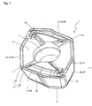
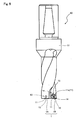
- the insert 1 includes an upper face 10, a bottom face 2 corresponding to the upper face 10, and a side face 20 located between the upper face 10 and the bottom face 2.
- the upper face 10 functions as a rake face through which generated chips graze.
- the upper face 10 includes a first corner portion 11, and a first side 12 and a second side 13 respectively disposed on both sides of the first corner portion 11.
- the upper face 10 has a substantially square shape, specifically substantially rhombus shape when viewed from above as shown in Fig. 2(a) .
- a through-hole 3 is formed in the middle section of the upper face 10.
- the through-hole 3 is used for screw fastening, and extends from the upper face 10 to the bottom face 2.
- the insert 1 has a 180-degree rotationally symmetrical shape with the central axis of the through-hole 3 as the rotation axis. Therefore, the upper face 10 has a pair of first corner portions 11 and 11 opposing each other, a pair of first sides 12 and 12 opposing each other, and a pair of second sides 13 and 13 opposing each other.
- the paired first corner portions 11 and 11 are located on one diagonal of the upper face 10.
- the upper face 10 also has a pair of second corner portions 14 and 14 located on the other diagonal of the upper face 10.
- the first corner portions 11 are located at obtuse angle corners
- the second corner portions 14 are located at acute angle corners, respectively.
- the insert 1 has first cutting edges 15 formed along the first sides 12, and second cutting edges 16 formed along the second sides 13, respectively.
- the first cutting edge 15 and the second cutting edge 16 are disposed adjacent each other through the first corner portion 11.
- the side face 20 has a first region 25 corresponding to the first cutting edge 15, a second region 26 corresponding to the second cutting edge 16, and a third region 21 corresponding to the first corner portion 11.
- Each of the first region 25, the second region 26, and the third region 21 functions as a flank face.
- the flank face may be the side face of the insert which functions as the flank face with respect to the substantially corresponding cutting edge. That is, the flank face corresponding to the cutting edge is not limited to the side face directly connected to the corresponding cutting edge.
- the third region 21 has an upper region 22 which is adjacent to the first corner portion 11 and disposed toward the upper face 10, and a lower region 23 located below the upper region 22.
- the upper region 22 is connected to the first region 25 and the second region 26, as shown in Fig. 2(b) and 2(c) . That is, the upper region 22 is smoothly connected to the first region 25 and the second region 26.
- the lower region 23 is formed planely.
- the first region 25 has an inclination angle ⁇ 1 to the bottom face 2.
- the second region 26 has an inclination angle ⁇ 2 to the bottom face 2.
- the upper region 22 has an inclination angle ⁇ 4 to the bottom face 2.
- the inclination angle ⁇ 4 is equal to the inclination angle ⁇ 1 at one end located toward the first region 25 and equal to the inclination angle ⁇ 2 at the other end located toward the second region 26.
- the lower region 23 has an inclination angle ⁇ 3 to the bottom face 2.
- the inclination angle ⁇ 3 is larger than each of the inclination angle ⁇ 1 and the inclination angle ⁇ 2.
- the cutting edge strength in the vicinity of the first corner portion 11 can be ensured by the upper region 22 continuous with the first corner portion 11. Additionally, when the insert 1 is attached to the holder as the outer insert, a constraining side face of the insert pocket opposed to one of the first corner portion 11 located on the side not to be involved in cutting in the insert 1 can be located further inside the holder.
- the insert 1 is attached to a second insert pocket 70 as the outer insert 1B so that a part of the second cutting edge 16 protrudes from the tip end of the holder 51.
- the first corner portion 11a of the paired first corner portions 11 and 11 which is located on the side not to be involved in the cutting in the insert 1 is disposed toward the outer periphery of the holder 51 in the second insert pocket 70 and disposed on the basal end of the holder 51.
- the inclination angle ⁇ 3 in the lower region 23 of the first corner portion 11a is large.
- the inserts of the present embodiment are capable of suitably reducing the holder breakage due to the insufficient strength of the portion of the holder during the high feed machining.
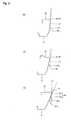
- the inclination angle (clearance angle) can be found as an angle formed between a line L1 substantially vertical to a flat mounting surface on which the insert 1 is placed, and each region. That is, in the cross section substantially vertical to the cutting edge corresponding to each region as shown in Figs. 3(a) to 3(C) , the angle formed between the line L1 substantially vertical to the bottom face 2 and each region can be employed as the inclination angle.
- the inclination angle ⁇ 2 is larger than the inclination angle ⁇ 1 ( ⁇ 2> ⁇ 1).
- the inclination angle ⁇ 4 increases as it goes from the first region 25 to the second region 26.
- the inclination angle ⁇ 3 is constant in the direction along the first corner portion 11.
- a heightwise dimension H1 of the lower region 23 is larger than a heightwise dimension H2 of the upper region 22 (H1>H2).
- H1>H2 a heightwise dimension of the upper region 22
- a widthwise dimension W of the lower region 23 increases as it goes from the upper face 10 to the bottom face 2. This increases the area of the lower region 23. Therefore, the thickness of the outer wall S2 can be increased to enhance the strength of the holder.
- the widthwise dimension W means the maximum value among the dimensions in the direction substantially parallel to the bottom face 2 when the insert 1 is placed on the flat mounting surface.
- the insert according to the present invention is not limited to those having the shape of the insert 1. That is, when attached to the insert pocket in an embodiment of the insert according to the present invention, the side face corresponding to the corner portion located toward the outer periphery of the holder and located toward the basal end in the insert pocket has the construction as described above.
- the insert according to other embodiment of the present invention can also be adapted to produce the above effect if attached to the holder as either one of the inner insert and the outer insert. That is, as shown in Fig. 5 , the insert according to other embodiment of the present invention can also be adapted so that, when attached to the first insert pocket 60 and the second insert pocket 70 as the inner insert 1A and the outer insert 1B, respectively, the side face which is located toward the outer periphery of the holder 51 in the insert pocket and also located toward the basal end of the holder 51, and which corresponds to the corner portion located on the side not to be involved in the cutting has the above construction.
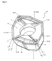
- a first cutting edge 15 is formed adjacent to two second cutting edges 16 and 16, and one end thereof is connected to a first corner portion 11 and the other end thereof is connected to a second corner portion 31.
- one end of the second cutting edges 16 is connected to the first corner portion 11, and the other is connected to the second corner portion 31.
- a side face 20 further has a fourth region 32 corresponding to the second corner portion 31.
- the fourth region 32 has an upper region 33 which is adjacent to the second corner portion 31 and disposed toward an upper face 10, and a lower region 34 located below the upper region 33.
- An inclination angle ⁇ 5 (not shown) of the lower region 34 to a bottom face 2 is larger than each of the inclination angle ⁇ 1 and the inclination angle ⁇ 2. That is, in the insert 30, both of the inclination angle ⁇ 3 and the inclination angle ⁇ 5 are larger than each of the inclination angle ⁇ 1 and the inclination angle ⁇ 2.
- the insert 30 when the insert 30 is applied to both of the inner insert 1A and the outer insert 1B, as shown in Fig. 6 , it is capable of ensuring large thicknesses of outer walls S1 and S2 of the holder which are located toward the outer periphery of the holder 51 in their respective corresponding insert pockets.
- the strengths of portions of the holder 51 where first and second insert pockets 60 and 70 are formed can be enhanced, thus enhancing the effect of reducing breakage of the holder 51.
- the insert 30 ensures the large thickness of the basal end of the outer wall S1 as described above. Even in the insert whose upper view has the substantially rhombus shape, the strength of the basal end of the outer wall S1 can be enhanced, thereby reducing breakage of the holder during machining.
- Other constructions are similar to those in the insert 1 according to the foregoing embodiment.
- a drill according to one embodiment of the present invention is described below in detail with reference of Figs. 5 to 7 by taking, for example, the case of attaching the insert 1 thereto.
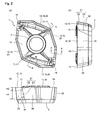
- the drill 50 according to the present embodiment is constructed by attaching two inserts 1 to the tip end of the holder 51.
- the drill 50 includes an inner insert 1A attached to the inner side of the tip end of the holder 51, and an outer insert 1B attached to the outer side thereof.
- a first insert pocket 60 (inner peripheral insert pocket) and a second insert pocket 70 (outer peripheral insert pocket) are respectively formed at the tip end of the holder 51.
- the first insert pocket 60 is formed toward the inner periphery of the tip end of the holder 51.
- the second insert pocket 70 is formed at the tip end of the holder 51 and toward the outer periphery of the holder 51 than the first insert pocket 60.
- the inner insert 1A is attached to the first insert pocket 60 so that at least a part of the first cutting edge 15 protrudes from the tip end of the holder 51.
- the inner insert 1A is attached so that the first corner portion 11 is located toward the outer periphery of the holder 51 at the tip end of the holder 51.
- the outer insert 1B is attached to the second insert pocket 70 so that at least a part of the second cutting edge 16 protrudes from the tip end of the holder 51.
- the outer insert 1B is attached so that the first corner portion 11 is located toward the inner periphery of the holder 51, and the second corner portion 14 is located toward the outer periphery of the holder 51 at the tip end of the holder 51.
- the first cutting edge 15 of the inner insert 1A functions as the inner cutting edge for cutting the inner side of the bottom face of a hole
- the second cutting edge 16 of the outer insert 1B functions as the outer cutting edge for cutting the outer side of the bottom face of the hole.
- the first corner portion 11a of the paired first corner portions 11 and 11 of the outer insert 1B which is located on the side not to be involved in the cutting is disposed toward the outer periphery of the holder 51 in the second insert pocket 70 and disposed on the basal end side of the holder 51.
- the inclination angle ⁇ 3 in the lower region 23 below the first corner portion 11a is larger than each of the inclination angle ⁇ 1 and the inclination angle ⁇ 2. It is therefore capable of ensuring a large thickness of the outer wall S2 of the holder 51 located toward the outer periphery of the holder 51 in the second insert pocket 70 and located toward the basal end of the holder 51, as shown in Fig. 6(b) . This achieves the holder 51 in which the outer wall S2 has high strength, thereby improving the lifetime of the holder. Consequently, the drill 50 is capable of reducing the breakage of the holder caused due to insufficient strength of the outer wall during machining as has been conventional, thereby exhibiting excellent cutting performance over a long period of time.
- first insert pocket 60 and the second insert pocket 70 have constraining seat faces 61 and 71, first constraining side faces 62 and 72, second constraining side faces 63 and 73, and third constraining side faces 64 and 74, respectively, as shown in Figs. 6(a) and 6(b) .
- These first constraining side faces 62 and 72 are located toward the inner periphery of the holder 51
- these second constraining side faces 63 and 73 are located toward the outer periphery of the holder 51.
- These third constraining side faces 64 and 74 are located toward the basal end of the holder 51 between these first constraining side faces 62 and 72 and these constraining second constraining side faces 63 and 73.
- These constraining seat faces 61 and 71 contact against the bottom face 2 of the insert 1.
- the first and third constraining side faces 62, 64, 72 and 74 contact against the side face 20 of the insert 1.
- first constraining side faces 62 and 72, and these second constraining side faces 63 and 73 of the first insert pocket 60 and the second insert pocket 70 have different arrangements so as to correspond to the shapes of the inner insert 1A and the outer insert 1B to be attached, respectively.
- first constraining side face 62 and the second constraining side face 63 of the first insert pocket 60 are disposed incliningly away from the outer peripheral face of the holder 51 constituting the outer wall S1 as they go from the basal end to the tip end of the holder 51.
- the second constraining side face 72 and the second constraining side face 73 of the second insert pocket 70 are disposed incliningly away from the outer peripheral face of the holder 51 into which the second insert pocket 70 opens, as they go from the tip end to the basal end of the holder 51.
- the second insert pocket 70 is formed so that a lower part 76 of the second constraining side face 73 protrudes inward of the holder 51. More specifically, an upper part 75 of the second constraining side face 73 is formed incliningly away from the outer peripheral face of the holder 51 as it goes toward the constraining seat face 71, and a lower part 76 is formed protrudingly inward of the holder 51 so as to form a step from the upper part 75.
- Fig. 7(b) is the sectional view vertical to the constraining seat face 71 of the second insert pocket 70.
- the outer insert 1B is attached to the second insert pocket 70 so that the third region 21, more specifically the lower region 23 corresponding to the first corner portion 11a located on the side not to be involved in the cutting is opposed to the lower part 76. Thereby, the strength of the outer wall S2 can be efficiently improved.
- the lower part 76 is formed to have the step portion including an upper face 76a substantially parallel to the constraining seat face 71, the construction of the lower part is not limited thereto.
- the lower part may be formed planely as long as it protrudes inward of the holder 51.
- an inclination angle ⁇ 6 of the second constraining side face 73 to the constraining seat face 71 is smaller than the inclination angle ⁇ 3 corresponding to the first corner portion 11a opposed to the second constraining side face 73 and located on the side not to be involved in the cutting ( ⁇ 6 ⁇ 3).
- This increases the thickness of the outer wall S2, thereby ensuring the strength of the holder 51 and reducing the interference between the lower region 23 of the outer insert 1B and the second constraining side face 73. Consequently, the lifetime of the entire drill can be improved to achieve stable cutting (machining) over a long period of time.
- the inclination angle ⁇ 6 can be obtained as an angle formed between a line L2 substantially vertical to the constraining seat face 71 and the second constraining side face 73 in the cross section substantially vertical to the constraining seat face 71.
- the drill and the holder according to the present invention are not limited to the present embodiment.
- the drill may be constructed by including the holder in which, similarly to the second insert pocket 70, the first insert pocket 60 also has the foregoing construction.
- the holder may be one in which only the first insert pocket 60 has the foregoing construction.
- the method of cutting the work material according to the present embodiment includes the following steps (i) to (iv):
- the cutting is carried out using the drill 50 which is capable of reducing the breakage of the holder 51 during the cutting and has a long tool life, so that the cutting (machining) with excellent machining accuracy can be stably achieved over a long period of time.
- either one of the drill 50 and the work material 100 may be rotated.
- the individual cutting edges 15 and 16 and the work material 100 may be relatively brought near.
- the work material 100 may be brought near the individual cutting edges 15 and 16.
- the work material 100 and the individual cutting edges 15 and 16 may be relatively separated.
- the work material 100 may be separated from the individual cutting edges 15 and 16.
- the present invention is not limited to the foregoing embodiments. It is needless to say that the present invention can optionally be embodied as long as it does not depart from the aim of the present invention.
- the present invention may be the insert in which, when attached to the first insert pocket as the inner insert, the side face corresponding to the corner portion located toward the outer periphery of the holder in the first insert pocket and disposed toward the basal end of the holder and located on the side not to be involved in the cutting may have the foregoing construction.
- the lower region 23 is formed planely in the foregoing embodiment, the lower region may be formed in a curved surface shape.
Landscapes
- Engineering & Computer Science (AREA)
- Mechanical Engineering (AREA)
- Drilling Tools (AREA)
Applications Claiming Priority (2)
| Application Number | Priority Date | Filing Date | Title |
|---|---|---|---|
| JP2008045524 | 2008-02-27 | ||
| PCT/JP2009/053709 WO2009107789A1 (ja) | 2008-02-27 | 2009-02-27 | ドリル用切削インサートおよびドリル、並びにそれを用いた切削方法 |
Publications (3)
| Publication Number | Publication Date |
|---|---|
| EP2260960A1 true EP2260960A1 (de) | 2010-12-15 |
| EP2260960A4 EP2260960A4 (de) | 2011-02-16 |
| EP2260960B1 EP2260960B1 (de) | 2014-12-17 |
Family
ID=41016174
Family Applications (1)
| Application Number | Title | Priority Date | Filing Date |
|---|---|---|---|
| EP09714448.9A Active EP2260960B1 (de) | 2008-02-27 | 2009-02-27 | Schneideeinsatz für einen bohrer, bohrer und schneideverfahren damit |
Country Status (5)
| Country | Link |
|---|---|
| US (1) | US8911183B2 (de) |
| EP (1) | EP2260960B1 (de) |
| JP (1) | JP5060614B2 (de) |
| CN (1) | CN101959633B (de) |
| WO (1) | WO2009107789A1 (de) |
Cited By (1)
| Publication number | Priority date | Publication date | Assignee | Title |
|---|---|---|---|---|
| US20170341154A1 (en) * | 2014-12-05 | 2017-11-30 | Ceramtec Gmbh | Cutting insert geometry |
Families Citing this family (15)
| Publication number | Priority date | Publication date | Assignee | Title |
|---|---|---|---|---|
| US8337123B2 (en) * | 2007-05-28 | 2012-12-25 | Kyocera Corporation | Cutting insert, cutting tool, and cutting method using the cutting tool |
| US9403215B2 (en) * | 2011-04-11 | 2016-08-02 | Sumitomo Electric Industries, Ltd. | Cutting tool and method for producing same |
| KR101222291B1 (ko) | 2011-07-20 | 2013-01-15 | 대구텍 유한회사 | 드릴 공구 |
| JP5990584B2 (ja) | 2011-07-22 | 2016-09-14 | ケンナメタル インディア リミテッド | 割出し可能ドリルインサート |
| DE102012012980B4 (de) | 2011-07-22 | 2019-10-17 | Kennametal India Ltd. | Bohrwerkzeug |
| DE102012014092B4 (de) | 2011-07-22 | 2020-12-17 | Kennametal India Ltd. | Indexierbarer Bohreinsatz sowie Bohrkörper mit indexierbarem Bohreinsatz |
| US8621964B2 (en) | 2011-11-23 | 2014-01-07 | Kennametal Inc. | Rotary cutting tool with coolant passage disposed in non-circular recess for reducing stress |
| US8647026B2 (en) | 2011-11-23 | 2014-02-11 | Kennametal Inc. | Cutting tool with pocket feature for reducing stress |
| CN103447591B (zh) | 2012-05-28 | 2020-02-28 | 钴碳化钨硬质合金印度有限公司 | 四角形的可转位的钻头镶片 |
| CN105209198B (zh) | 2013-01-23 | 2017-04-05 | 钴碳化钨硬质合金印度有限公司 | 可转位钻刀片及采用该刀片的旋转切削工具 |
| US10556278B2 (en) | 2016-08-16 | 2020-02-11 | Kennametal Inc. | Tool body for a shell end mill and cutting tool |
| KR102386942B1 (ko) * | 2017-08-23 | 2022-04-14 | 대구텍 유한책임회사 | 드릴용 절삭 인서트 |
| CN112077369A (zh) | 2019-06-13 | 2020-12-15 | 肯纳金属印度有限公司 | 可转位钻头刀片 |
| CN112077370A (zh) | 2019-06-13 | 2020-12-15 | 肯纳金属印度有限公司 | 可转位钻头刀片 |
| CN112388033A (zh) | 2019-08-14 | 2021-02-23 | 肯纳金属印度有限公司 | 可转位钻头刀片 |
Citations (5)
| Publication number | Priority date | Publication date | Assignee | Title |
|---|---|---|---|---|
| EP0373292A1 (de) * | 1988-12-15 | 1990-06-20 | WALTER Aktiengesellschaft | Bohrwerkzeug für metallische Werkstoffe, Kunststoffe und dergl. |
| JPH07328815A (ja) * | 1994-06-06 | 1995-12-19 | Mitsubishi Materials Corp | スローアウェイチップ |
| US5688083A (en) * | 1993-05-20 | 1997-11-18 | Iscar Ltd. | Drilling tool and an indexing cutting insert for use therein |
| EP1949990A2 (de) * | 2007-01-29 | 2008-07-30 | Sandvik Intellectual Property AB | Indexierbarer Einsatzbohrer und Zentraleinsatz dafür |
| EP2167262A1 (de) * | 2007-06-14 | 2010-03-31 | Taegutec Ltd. | Bohrer mit schneideinsätzen |
Family Cites Families (17)
| Publication number | Priority date | Publication date | Assignee | Title |
|---|---|---|---|---|
| GB2116082A (en) | 1982-02-26 | 1983-09-21 | Gen Electric | Inserts for cutting tools |
| JP3525349B2 (ja) | 1994-03-14 | 2004-05-10 | 日本特殊陶業株式会社 | 切削工具用ホルダー |
| DE4411475A1 (de) * | 1994-04-01 | 1995-10-05 | Walter Ag | Schneidplatte, insbesondere Wendeschneidplatte |
| IL113122A0 (en) * | 1995-03-24 | 1995-06-29 | Iscar Ltd | A cutting insert |
| JP3329159B2 (ja) | 1995-10-25 | 2002-09-30 | 三菱マテリアル株式会社 | スローアウェイチップ及びスローアウェイ式転削工具 |
| JPH1029108A (ja) | 1996-07-11 | 1998-02-03 | Toshiba Tungaloy Co Ltd | スローアウェイ式ドリルおよびドリル用チップ |
| SE511224C2 (sv) * | 1997-04-30 | 1999-08-30 | Seco Tools Ab | Borrverktyg |
| SE519133C2 (sv) * | 1998-10-13 | 2003-01-21 | Sandvik Ab | Borrskär för metallborrning |
| US6939090B1 (en) * | 1999-08-17 | 2005-09-06 | Mitsubishi Materials Corporation | Throwaway tip and throwaway-type cutting tool |
| JP4688378B2 (ja) | 2001-09-26 | 2011-05-25 | 京セラ株式会社 | ドリル用スローアウェイチップ |
| US7220083B2 (en) * | 2003-10-15 | 2007-05-22 | Tdy Industries, Inc. | Cutting insert for high feed face milling |
| SE529979C2 (sv) * | 2006-01-30 | 2008-01-22 | Sandvik Intellectual Property | Borr och borrskär där mynningsytan i skärets hål har en tvärsnittsvis konvexform |
| JP4976181B2 (ja) * | 2006-12-25 | 2012-07-18 | 住友電工ハードメタル株式会社 | スローアウェイドリルのチップ配置方法 |
| US7905687B2 (en) * | 2007-01-16 | 2011-03-15 | Tdy Industries, Inc. | Cutting insert, tool holder, and related method |
| US7591614B2 (en) * | 2007-11-20 | 2009-09-22 | Kennametal Inc. | Cutting insert with serrations |
| US8062014B2 (en) * | 2007-11-27 | 2011-11-22 | Kennametal Inc. | Method and apparatus using a split case die to press a part and the part produced therefrom |
| US8840346B2 (en) * | 2008-05-23 | 2014-09-23 | Kyocera Corporation | Drill, cutting insert, and method of manufacturing cut product |
-
2009
- 2009-02-27 JP JP2010500776A patent/JP5060614B2/ja active Active
- 2009-02-27 CN CN200980106298.1A patent/CN101959633B/zh active Active
- 2009-02-27 WO PCT/JP2009/053709 patent/WO2009107789A1/ja active Application Filing
- 2009-02-27 US US12/918,463 patent/US8911183B2/en active Active
- 2009-02-27 EP EP09714448.9A patent/EP2260960B1/de active Active
Patent Citations (5)
| Publication number | Priority date | Publication date | Assignee | Title |
|---|---|---|---|---|
| EP0373292A1 (de) * | 1988-12-15 | 1990-06-20 | WALTER Aktiengesellschaft | Bohrwerkzeug für metallische Werkstoffe, Kunststoffe und dergl. |
| US5688083A (en) * | 1993-05-20 | 1997-11-18 | Iscar Ltd. | Drilling tool and an indexing cutting insert for use therein |
| JPH07328815A (ja) * | 1994-06-06 | 1995-12-19 | Mitsubishi Materials Corp | スローアウェイチップ |
| EP1949990A2 (de) * | 2007-01-29 | 2008-07-30 | Sandvik Intellectual Property AB | Indexierbarer Einsatzbohrer und Zentraleinsatz dafür |
| EP2167262A1 (de) * | 2007-06-14 | 2010-03-31 | Taegutec Ltd. | Bohrer mit schneideinsätzen |
Non-Patent Citations (1)
| Title |
|---|
| See also references of WO2009107789A1 * |
Cited By (2)
| Publication number | Priority date | Publication date | Assignee | Title |
|---|---|---|---|---|
| US20170341154A1 (en) * | 2014-12-05 | 2017-11-30 | Ceramtec Gmbh | Cutting insert geometry |
| US10307828B2 (en) * | 2014-12-05 | 2019-06-04 | Ceramtec Gmbh | Cutting insert geometry |
Also Published As
| Publication number | Publication date |
|---|---|
| CN101959633A (zh) | 2011-01-26 |
| US8911183B2 (en) | 2014-12-16 |
| JP5060614B2 (ja) | 2012-10-31 |
| WO2009107789A1 (ja) | 2009-09-03 |
| CN101959633B (zh) | 2014-04-16 |
| EP2260960B1 (de) | 2014-12-17 |
| JPWO2009107789A1 (ja) | 2011-07-07 |
| US20100329804A1 (en) | 2010-12-30 |
| EP2260960A4 (de) | 2011-02-16 |
Similar Documents
| Publication | Publication Date | Title |
|---|---|---|
| EP2260960B1 (de) | Schneideeinsatz für einen bohrer, bohrer und schneideverfahren damit | |
| CN103447591B (zh) | 四角形的可转位的钻头镶片 | |
| KR101083853B1 (ko) | 드릴링 가공 및 선삭 가공이 가능한 절삭 공구 | |
| JP5265936B2 (ja) | 割出し可能なインサートドリルとその中央インサート | |
| JP5369185B2 (ja) | 切削インサート及び切削工具、並びにそれを用いた切削加工物の製造方法 | |
| KR100656265B1 (ko) | 인덱서블 절삭공구 | |
| EP2514544A1 (de) | Bohrer und Schneideinsätze | |
| US8979443B2 (en) | Insert for drill | |
| US20100054884A1 (en) | Drill | |
| KR20130011958A (ko) | 인덱서블 드릴 인서트 | |
| KR101059288B1 (ko) | 드릴용 절삭공구 | |
| US20120076596A1 (en) | Reversible Cutting Insert and Tool Assembly Having the Same | |
| US20140056656A1 (en) | Turning tool for internal machining | |
| EP2532460A1 (de) | Rinnenformungswerkzeug zur ersetzung einer schneidekante sowie verfahren zur formierung einer endrinne | |
| JP4949890B2 (ja) | 切削インサートおよびスローアウェイ式ドリル並びに被削材の切削方法 | |
| KR100661527B1 (ko) | 개선된 칩브레이커를 가지는 절삭 인서트 | |
| US20210114118A1 (en) | Insert and cutting tool assembly comprising same | |
| KR100832869B1 (ko) | 절삭저항을 감소시키는 절삭 인서트 | |
| KR100662808B1 (ko) | 절삭 인서트 | |
| JP2003291003A (ja) | 切削工具 | |
| CN114867575B (zh) | 可转位刀片式切削工具保持架及可转位刀片式切削工具 | |
| EP3950197A1 (de) | Schneidwerkzeugkörper, schneideinsatz und schneidwerkzeug | |
| JP2001121307A (ja) | 切削工具 | |
| JP6318558B2 (ja) | 切削インサートおよび刃先交換式穴加工工具 | |
| KR100601323B1 (ko) | 비대칭형 트위스트 드릴 |
Legal Events
| Date | Code | Title | Description |
|---|---|---|---|
| PUAI | Public reference made under article 153(3) epc to a published international application that has entered the european phase |
Free format text: ORIGINAL CODE: 0009012 |
|
| 17P | Request for examination filed |
Effective date: 20100927 |
|
| AK | Designated contracting states |
Kind code of ref document: A1 Designated state(s): AT BE BG CH CY CZ DE DK EE ES FI FR GB GR HR HU IE IS IT LI LT LU LV MC MK MT NL NO PL PT RO SE SI SK TR |
|
| AX | Request for extension of the european patent |
Extension state: AL BA RS |
|
| A4 | Supplementary search report drawn up and despatched |
Effective date: 20110113 |
|
| DAX | Request for extension of the european patent (deleted) | ||
| 17Q | First examination report despatched |
Effective date: 20131220 |
|
| GRAP | Despatch of communication of intention to grant a patent |
Free format text: ORIGINAL CODE: EPIDOSNIGR1 |
|
| INTG | Intention to grant announced |
Effective date: 20140708 |
|
| GRAS | Grant fee paid |
Free format text: ORIGINAL CODE: EPIDOSNIGR3 |
|
| GRAA | (expected) grant |
Free format text: ORIGINAL CODE: 0009210 |
|
| AK | Designated contracting states |
Kind code of ref document: B1 Designated state(s): AT BE BG CH CY CZ DE DK EE ES FI FR GB GR HR HU IE IS IT LI LT LU LV MC MK MT NL NO PL PT RO SE SI SK TR |
|
| RAP1 | Party data changed (applicant data changed or rights of an application transferred) |
Owner name: KYOCERA CORPORATION |
|
| REG | Reference to a national code |
Ref country code: GB Ref legal event code: FG4D |
|
| REG | Reference to a national code |
Ref country code: CH Ref legal event code: EP |
|
| REG | Reference to a national code |
Ref country code: IE Ref legal event code: FG4D |
|
| REG | Reference to a national code |
Ref country code: AT Ref legal event code: REF Ref document number: 701522 Country of ref document: AT Kind code of ref document: T Effective date: 20150115 |
|
| REG | Reference to a national code |
Ref country code: DE Ref legal event code: R096 Ref document number: 602009028364 Country of ref document: DE Effective date: 20150129 |
|
| PG25 | Lapsed in a contracting state [announced via postgrant information from national office to epo] |
Ref country code: FI Free format text: LAPSE BECAUSE OF FAILURE TO SUBMIT A TRANSLATION OF THE DESCRIPTION OR TO PAY THE FEE WITHIN THE PRESCRIBED TIME-LIMIT Effective date: 20141217 Ref country code: LT Free format text: LAPSE BECAUSE OF FAILURE TO SUBMIT A TRANSLATION OF THE DESCRIPTION OR TO PAY THE FEE WITHIN THE PRESCRIBED TIME-LIMIT Effective date: 20141217 Ref country code: NO Free format text: LAPSE BECAUSE OF FAILURE TO SUBMIT A TRANSLATION OF THE DESCRIPTION OR TO PAY THE FEE WITHIN THE PRESCRIBED TIME-LIMIT Effective date: 20150317 |
|
| REG | Reference to a national code |
Ref country code: LT Ref legal event code: MG4D |
|
| PG25 | Lapsed in a contracting state [announced via postgrant information from national office to epo] |
Ref country code: GR Free format text: LAPSE BECAUSE OF FAILURE TO SUBMIT A TRANSLATION OF THE DESCRIPTION OR TO PAY THE FEE WITHIN THE PRESCRIBED TIME-LIMIT Effective date: 20150318 Ref country code: SE Free format text: LAPSE BECAUSE OF FAILURE TO SUBMIT A TRANSLATION OF THE DESCRIPTION OR TO PAY THE FEE WITHIN THE PRESCRIBED TIME-LIMIT Effective date: 20141217 Ref country code: HR Free format text: LAPSE BECAUSE OF FAILURE TO SUBMIT A TRANSLATION OF THE DESCRIPTION OR TO PAY THE FEE WITHIN THE PRESCRIBED TIME-LIMIT Effective date: 20141217 Ref country code: LV Free format text: LAPSE BECAUSE OF FAILURE TO SUBMIT A TRANSLATION OF THE DESCRIPTION OR TO PAY THE FEE WITHIN THE PRESCRIBED TIME-LIMIT Effective date: 20141217 |
|
| REG | Reference to a national code |
Ref country code: AT Ref legal event code: MK05 Ref document number: 701522 Country of ref document: AT Kind code of ref document: T Effective date: 20141217 |
|
| PG25 | Lapsed in a contracting state [announced via postgrant information from national office to epo] |
Ref country code: NL Free format text: LAPSE BECAUSE OF FAILURE TO SUBMIT A TRANSLATION OF THE DESCRIPTION OR TO PAY THE FEE WITHIN THE PRESCRIBED TIME-LIMIT Effective date: 20141217 |
|
| REG | Reference to a national code |
Ref country code: DE Ref legal event code: R082 Ref document number: 602009028364 Country of ref document: DE Representative=s name: VIERING, JENTSCHURA & PARTNER PATENT- UND RECH, DE Ref country code: DE Ref legal event code: R082 Ref document number: 602009028364 Country of ref document: DE Representative=s name: VIERING, JENTSCHURA & PARTNER MBB PATENT- UND , DE |
|
| PG25 | Lapsed in a contracting state [announced via postgrant information from national office to epo] |
Ref country code: SK Free format text: LAPSE BECAUSE OF FAILURE TO SUBMIT A TRANSLATION OF THE DESCRIPTION OR TO PAY THE FEE WITHIN THE PRESCRIBED TIME-LIMIT Effective date: 20141217 Ref country code: RO Free format text: LAPSE BECAUSE OF FAILURE TO SUBMIT A TRANSLATION OF THE DESCRIPTION OR TO PAY THE FEE WITHIN THE PRESCRIBED TIME-LIMIT Effective date: 20141217 Ref country code: ES Free format text: LAPSE BECAUSE OF FAILURE TO SUBMIT A TRANSLATION OF THE DESCRIPTION OR TO PAY THE FEE WITHIN THE PRESCRIBED TIME-LIMIT Effective date: 20141217 Ref country code: EE Free format text: LAPSE BECAUSE OF FAILURE TO SUBMIT A TRANSLATION OF THE DESCRIPTION OR TO PAY THE FEE WITHIN THE PRESCRIBED TIME-LIMIT Effective date: 20141217 Ref country code: CZ Free format text: LAPSE BECAUSE OF FAILURE TO SUBMIT A TRANSLATION OF THE DESCRIPTION OR TO PAY THE FEE WITHIN THE PRESCRIBED TIME-LIMIT Effective date: 20141217 |
|
| PG25 | Lapsed in a contracting state [announced via postgrant information from national office to epo] |
Ref country code: PL Free format text: LAPSE BECAUSE OF FAILURE TO SUBMIT A TRANSLATION OF THE DESCRIPTION OR TO PAY THE FEE WITHIN THE PRESCRIBED TIME-LIMIT Effective date: 20141217 Ref country code: AT Free format text: LAPSE BECAUSE OF FAILURE TO SUBMIT A TRANSLATION OF THE DESCRIPTION OR TO PAY THE FEE WITHIN THE PRESCRIBED TIME-LIMIT Effective date: 20141217 Ref country code: IS Free format text: LAPSE BECAUSE OF FAILURE TO SUBMIT A TRANSLATION OF THE DESCRIPTION OR TO PAY THE FEE WITHIN THE PRESCRIBED TIME-LIMIT Effective date: 20150417 |
|
| REG | Reference to a national code |
Ref country code: DE Ref legal event code: R082 Ref document number: 602009028364 Country of ref document: DE Representative=s name: VIERING, JENTSCHURA & PARTNER PATENT- UND RECH, DE Ref country code: DE Ref legal event code: R082 Ref document number: 602009028364 Country of ref document: DE Representative=s name: VIERING, JENTSCHURA & PARTNER MBB PATENT- UND , DE Ref country code: DE Ref legal event code: R097 Ref document number: 602009028364 Country of ref document: DE |
|
| PG25 | Lapsed in a contracting state [announced via postgrant information from national office to epo] |
Ref country code: LU Free format text: LAPSE BECAUSE OF FAILURE TO SUBMIT A TRANSLATION OF THE DESCRIPTION OR TO PAY THE FEE WITHIN THE PRESCRIBED TIME-LIMIT Effective date: 20150227 |
|
| REG | Reference to a national code |
Ref country code: CH Ref legal event code: PL |
|
| PLBE | No opposition filed within time limit |
Free format text: ORIGINAL CODE: 0009261 |
|
| STAA | Information on the status of an ep patent application or granted ep patent |
Free format text: STATUS: NO OPPOSITION FILED WITHIN TIME LIMIT |
|
| PG25 | Lapsed in a contracting state [announced via postgrant information from national office to epo] |
Ref country code: MC Free format text: LAPSE BECAUSE OF FAILURE TO SUBMIT A TRANSLATION OF THE DESCRIPTION OR TO PAY THE FEE WITHIN THE PRESCRIBED TIME-LIMIT Effective date: 20141217 Ref country code: DK Free format text: LAPSE BECAUSE OF FAILURE TO SUBMIT A TRANSLATION OF THE DESCRIPTION OR TO PAY THE FEE WITHIN THE PRESCRIBED TIME-LIMIT Effective date: 20141217 Ref country code: LI Free format text: LAPSE BECAUSE OF NON-PAYMENT OF DUE FEES Effective date: 20150228 Ref country code: CH Free format text: LAPSE BECAUSE OF NON-PAYMENT OF DUE FEES Effective date: 20150228 |
|
| REG | Reference to a national code |
Ref country code: IE Ref legal event code: MM4A |
|
| 26N | No opposition filed |
Effective date: 20150918 |
|
| GBPC | Gb: european patent ceased through non-payment of renewal fee |
Effective date: 20150317 |
|
| REG | Reference to a national code |
Ref country code: FR Ref legal event code: ST Effective date: 20151030 |
|
| PG25 | Lapsed in a contracting state [announced via postgrant information from national office to epo] |
Ref country code: IT Free format text: LAPSE BECAUSE OF FAILURE TO SUBMIT A TRANSLATION OF THE DESCRIPTION OR TO PAY THE FEE WITHIN THE PRESCRIBED TIME-LIMIT Effective date: 20141217 |
|
| PG25 | Lapsed in a contracting state [announced via postgrant information from national office to epo] |
Ref country code: GB Free format text: LAPSE BECAUSE OF NON-PAYMENT OF DUE FEES Effective date: 20150317 Ref country code: IE Free format text: LAPSE BECAUSE OF NON-PAYMENT OF DUE FEES Effective date: 20150227 |
|
| PG25 | Lapsed in a contracting state [announced via postgrant information from national office to epo] |
Ref country code: FR Free format text: LAPSE BECAUSE OF NON-PAYMENT OF DUE FEES Effective date: 20150302 Ref country code: SI Free format text: LAPSE BECAUSE OF FAILURE TO SUBMIT A TRANSLATION OF THE DESCRIPTION OR TO PAY THE FEE WITHIN THE PRESCRIBED TIME-LIMIT Effective date: 20141217 |
|
| PG25 | Lapsed in a contracting state [announced via postgrant information from national office to epo] |
Ref country code: BE Free format text: LAPSE BECAUSE OF FAILURE TO SUBMIT A TRANSLATION OF THE DESCRIPTION OR TO PAY THE FEE WITHIN THE PRESCRIBED TIME-LIMIT Effective date: 20141217 |
|
| PG25 | Lapsed in a contracting state [announced via postgrant information from national office to epo] |
Ref country code: MT Free format text: LAPSE BECAUSE OF FAILURE TO SUBMIT A TRANSLATION OF THE DESCRIPTION OR TO PAY THE FEE WITHIN THE PRESCRIBED TIME-LIMIT Effective date: 20141217 |
|
| PG25 | Lapsed in a contracting state [announced via postgrant information from national office to epo] |
Ref country code: HU Free format text: LAPSE BECAUSE OF FAILURE TO SUBMIT A TRANSLATION OF THE DESCRIPTION OR TO PAY THE FEE WITHIN THE PRESCRIBED TIME-LIMIT; INVALID AB INITIO Effective date: 20090227 Ref country code: BG Free format text: LAPSE BECAUSE OF FAILURE TO SUBMIT A TRANSLATION OF THE DESCRIPTION OR TO PAY THE FEE WITHIN THE PRESCRIBED TIME-LIMIT Effective date: 20141217 |
|
| PG25 | Lapsed in a contracting state [announced via postgrant information from national office to epo] |
Ref country code: CY Free format text: LAPSE BECAUSE OF FAILURE TO SUBMIT A TRANSLATION OF THE DESCRIPTION OR TO PAY THE FEE WITHIN THE PRESCRIBED TIME-LIMIT Effective date: 20141217 |
|
| PG25 | Lapsed in a contracting state [announced via postgrant information from national office to epo] |
Ref country code: PT Free format text: LAPSE BECAUSE OF FAILURE TO SUBMIT A TRANSLATION OF THE DESCRIPTION OR TO PAY THE FEE WITHIN THE PRESCRIBED TIME-LIMIT Effective date: 20150417 |
|
| PG25 | Lapsed in a contracting state [announced via postgrant information from national office to epo] |
Ref country code: TR Free format text: LAPSE BECAUSE OF FAILURE TO SUBMIT A TRANSLATION OF THE DESCRIPTION OR TO PAY THE FEE WITHIN THE PRESCRIBED TIME-LIMIT Effective date: 20141217 |
|
| PG25 | Lapsed in a contracting state [announced via postgrant information from national office to epo] |
Ref country code: MK Free format text: LAPSE BECAUSE OF FAILURE TO SUBMIT A TRANSLATION OF THE DESCRIPTION OR TO PAY THE FEE WITHIN THE PRESCRIBED TIME-LIMIT Effective date: 20141217 |
|
| P01 | Opt-out of the competence of the unified patent court (upc) registered |
Effective date: 20230508 |
|
| PGFP | Annual fee paid to national office [announced via postgrant information from national office to epo] |
Ref country code: DE Payment date: 20231229 Year of fee payment: 16 |