EP2260490B1 - Optisches speichermedium mit umgekehrten hochauflösenden höhen und tiefen - Google Patents
Optisches speichermedium mit umgekehrten hochauflösenden höhen und tiefen Download PDFInfo
- Publication number
- EP2260490B1 EP2260490B1 EP09717740A EP09717740A EP2260490B1 EP 2260490 B1 EP2260490 B1 EP 2260490B1 EP 09717740 A EP09717740 A EP 09717740A EP 09717740 A EP09717740 A EP 09717740A EP 2260490 B1 EP2260490 B1 EP 2260490B1
- Authority
- EP
- European Patent Office
- Prior art keywords
- land
- pit
- pits
- lands
- storage medium
- Prior art date
- Legal status (The legal status is an assumption and is not a legal conclusion. Google has not performed a legal analysis and makes no representation as to the accuracy of the status listed.)
- Not-in-force
Links
- 230000003287 optical effect Effects 0.000 title claims abstract description 66
- 238000003860 storage Methods 0.000 title claims abstract description 51
- 229910000763 AgInSbTe Inorganic materials 0.000 claims abstract description 23
- 239000000758 substrate Substances 0.000 claims abstract description 13
- 239000012782 phase change material Substances 0.000 claims abstract description 10
- 239000000463 material Substances 0.000 claims description 20
- 150000004770 chalcogenides Chemical class 0.000 claims description 6
- 229910000618 GeSbTe Inorganic materials 0.000 claims description 2
- 230000000149 penetrating effect Effects 0.000 claims description 2
- 230000000694 effects Effects 0.000 abstract description 12
- 239000010410 layer Substances 0.000 description 73
- 238000002310 reflectometry Methods 0.000 description 17
- WPYVAWXEWQSOGY-UHFFFAOYSA-N indium antimonide Chemical compound [Sb]#[In] WPYVAWXEWQSOGY-UHFFFAOYSA-N 0.000 description 14
- 239000004065 semiconductor Substances 0.000 description 8
- 230000008859 change Effects 0.000 description 5
- 238000001514 detection method Methods 0.000 description 5
- 230000007246 mechanism Effects 0.000 description 4
- 230000001419 dependent effect Effects 0.000 description 3
- 238000009826 distribution Methods 0.000 description 3
- 230000003595 spectral effect Effects 0.000 description 3
- 230000007423 decrease Effects 0.000 description 2
- 238000010438 heat treatment Methods 0.000 description 2
- 238000004088 simulation Methods 0.000 description 2
- 230000007704 transition Effects 0.000 description 2
- OAICVXFJPJFONN-UHFFFAOYSA-N Phosphorus Chemical compound [P] OAICVXFJPJFONN-UHFFFAOYSA-N 0.000 description 1
- BUGBHKTXTAQXES-UHFFFAOYSA-N Selenium Chemical compound [Se] BUGBHKTXTAQXES-UHFFFAOYSA-N 0.000 description 1
- NINIDFKCEFEMDL-UHFFFAOYSA-N Sulfur Chemical compound [S] NINIDFKCEFEMDL-UHFFFAOYSA-N 0.000 description 1
- 239000005864 Sulphur Substances 0.000 description 1
- 230000004913 activation Effects 0.000 description 1
- 229910052782 aluminium Inorganic materials 0.000 description 1
- XAGFODPZIPBFFR-UHFFFAOYSA-N aluminium Chemical compound [Al] XAGFODPZIPBFFR-UHFFFAOYSA-N 0.000 description 1
- 229910052787 antimony Inorganic materials 0.000 description 1
- WATWJIUSRGPENY-UHFFFAOYSA-N antimony atom Chemical compound [Sb] WATWJIUSRGPENY-UHFFFAOYSA-N 0.000 description 1
- 229910052785 arsenic Inorganic materials 0.000 description 1
- RQNWIZPPADIBDY-UHFFFAOYSA-N arsenic atom Chemical compound [As] RQNWIZPPADIBDY-UHFFFAOYSA-N 0.000 description 1
- 229910052681 coesite Inorganic materials 0.000 description 1
- 150000001875 compounds Chemical class 0.000 description 1
- 229910052906 cristobalite Inorganic materials 0.000 description 1
- 230000003247 decreasing effect Effects 0.000 description 1
- 239000002355 dual-layer Substances 0.000 description 1
- 230000006870 function Effects 0.000 description 1
- 229910052732 germanium Inorganic materials 0.000 description 1
- GNPVGFCGXDBREM-UHFFFAOYSA-N germanium atom Chemical compound [Ge] GNPVGFCGXDBREM-UHFFFAOYSA-N 0.000 description 1
- 230000003993 interaction Effects 0.000 description 1
- 238000004519 manufacturing process Methods 0.000 description 1
- 238000005259 measurement Methods 0.000 description 1
- 229910044991 metal oxide Inorganic materials 0.000 description 1
- 150000004706 metal oxides Chemical class 0.000 description 1
- 230000009022 nonlinear effect Effects 0.000 description 1
- 229920000642 polymer Polymers 0.000 description 1
- 239000011241 protective layer Substances 0.000 description 1
- 230000004044 response Effects 0.000 description 1
- 229910052711 selenium Inorganic materials 0.000 description 1
- 239000011669 selenium Substances 0.000 description 1
- 238000004904 shortening Methods 0.000 description 1
- 239000000377 silicon dioxide Substances 0.000 description 1
- VYPSYNLAJGMNEJ-UHFFFAOYSA-N silicon dioxide Inorganic materials O=[Si]=O VYPSYNLAJGMNEJ-UHFFFAOYSA-N 0.000 description 1
- 229910052682 stishovite Inorganic materials 0.000 description 1
- 229910052714 tellurium Inorganic materials 0.000 description 1
- PORWMNRCUJJQNO-UHFFFAOYSA-N tellurium atom Chemical compound [Te] PORWMNRCUJJQNO-UHFFFAOYSA-N 0.000 description 1
- 238000002834 transmittance Methods 0.000 description 1
- 229910052905 tridymite Inorganic materials 0.000 description 1
Images

Classifications
-
- G—PHYSICS
- G11—INFORMATION STORAGE
- G11B—INFORMATION STORAGE BASED ON RELATIVE MOVEMENT BETWEEN RECORD CARRIER AND TRANSDUCER
- G11B7/00—Recording or reproducing by optical means, e.g. recording using a thermal beam of optical radiation by modifying optical properties or the physical structure, reproducing using an optical beam at lower power by sensing optical properties; Record carriers therefor
- G11B7/24—Record carriers characterised by shape, structure or physical properties, or by the selection of the material
- G11B7/2407—Tracks or pits; Shape, structure or physical properties thereof
- G11B7/24085—Pits
-
- G—PHYSICS
- G11—INFORMATION STORAGE
- G11B—INFORMATION STORAGE BASED ON RELATIVE MOVEMENT BETWEEN RECORD CARRIER AND TRANSDUCER
- G11B7/00—Recording or reproducing by optical means, e.g. recording using a thermal beam of optical radiation by modifying optical properties or the physical structure, reproducing using an optical beam at lower power by sensing optical properties; Record carriers therefor
- G11B7/24—Record carriers characterised by shape, structure or physical properties, or by the selection of the material
Definitions
- the present invention relates to an optical storage medium comprising a substrate layer, a data layer and a nonlinear layer with a super-resolution structure arranged above the data layer.
- the data layer comprises in particular pits and lands having a size above a diffraction limit and pits and lands having a size below said diffraction limit of a pickup for reading of the data as arranged on the data layer.
- Optical storage media are media in which data are stored in an optically readable manner, for example by means of a laser and an optical detector, for example a photodetector, being integrated within a pickup.
- the detector is used for detecting reflected light of the laser beam when reading data on the storage medium.
- optical storage media which are operated with different laser wavelength, and which have different sizes for providing storage capacities from below one Gigabyte up to 50 Gigabyte (GB).
- the formats include read-only formats such as Audio CD and Video DVD, write-once optical media such as CD-R and DVD-R, DVD+R, as well as rewritable formats like CD-RW, DVD-RW and DVD+RW. Digital data are stored on these media along tracks in one or more layers of the media.
- the storage medium with the highest data capacity is at present the Blu-Ray disc (BD), which allows to store up to about 50 GB on a dual layer disc.
- BD Blu-Ray disc
- On the Blu-Ray disc a track pitch of 320 nm and a mark length from 2T to 8T or 9T is used, where T is the channel bit length and wherein 2T corresponds with a minimum mark length of 138 - 160 nm.
- a higher resolution can be obtained because of the differential signal detection, when the laser beam moves over the pits and lands of a track on the Blu-Ray disc.
- New optical storage media with a super-resolution structure offer the possibility to increase the data density of the optical storage medium by a factor of two to four in one dimension as compared with the Blu-Ray disc.
- This is possible by including a nonlinear layer, which is placed above a data layer of the optical storage medium, and which significantly reduces the effective size of a light spot used for reading from or writing to the optical storage medium.
- the nonlinear layer can be understood as a mask layer because it is arranged above the data layer and for some specific materials only the high intensity center part of a laser beam can penetrate the mask layer.
- semiconductor materials can be used as a nonlinear layer, e.g.
- the nonlinear layer is often called a super-resolution near-field structure (Super-RENS) layer because it is assumed that for some specific materials, the optical effect of reducing the effective spot size of the laser beam is based on a near-field interaction between the marks and spaces of the data layer and the nonlinear layer.
- Super-RENS optical discs comprising a super resolution near-field structure formed of a metal oxide, a polymer compound or a phase change layer comprising a GeSbTe or a AgInSbTe are known.
- An optical storage medium comprising a read-only data layer, a substrate layer and a non-linear layer as described in the preamble of claim 1 is disclosed in EP-A-01074984 , US 2005/0157631 , US 2003/0107977 and US 2005/0079313 .
- the optical storage medium comprises a substrate layer, a read-only data layer having a pit/land data structure with data arranged in tracks on the substrate layer, and a nonlinear layer with a super-resolution structure disposed on the data layer, wherein the data structure comprises pits and lands having a size above a diffraction limit of a pickup for reading of the data and pits and lands having a size below the diffraction limit.
- a land having a size below the diffraction limit is inverted to a pit and is enclosed by auxiliary lands, and a pit having a size below the diffraction limit is inverted to a land and is enclosed by auxiliary pits.
- the super-resolution structure comprises in particular a phase change material, for example a chalcogenide material, providing an "aperture" type super-resolution mechanism, when irradiated with a high intensity laser beam of the pickup.
- a phase change material for example a chalcogenide material
- an inverted data structure is provided for the smallest pits and lands on the optical storage medium, to solve the problem of the inverted signal of the smallest pits and lands of the read out signal when reading the data on the optical storage medium. This allows a correct decoding of the data as arranged on the tracks of the data layer of the optical storage medium.
- an inverted land is separated from the preceding pit by an auxiliary land and separated from the subsequent pit by an auxiliary land
- an inverted pit is separated from the preceding land by an auxiliary pit and separated from the subsequent land by an auxiliary pit, wherein the auxiliary lands and pits have a size being below the diffraction limit.
- the auxiliary lands have for example a size corresponding with a 1T land and the auxiliary pits have a size corresponding with a 1T pit, and a diffractive land preceding or a diffractive land following an inverted pit is shortened by a length corresponding with the length of the auxiliary pit , and a diffractive pit preceding or a diffractive pit following an inverted land is shortened by a length corresponding with the length of the auxiliary land.
- the pits and lands of a track having a size below the diffraction limit are in particular 2T and/or 3T pits and lands, wherein the diffraction limit is defined as lambda/4NA.
- the optical storage medium is in a further aspect of the invention a ROM disc, comprising pits and lands as marks and spaces, the pits being molded or embossed on the surface of the substrate by using a respective stamper.
- FIG. 1 an optical storage medium 1 is shown in a cross section in a simplified manner.
- the optical storage medium 1 is for example a read-only (ROM) optical storage disc.
- a data layer 3 is arranged which may comprise a reflective metallic layer, for example an aluminum layer.
- the data layer 3 has a data structure consisting of marks and spaces arranged on essentially parallel tracks. In the case of a ROM disc, the marks and spaces consist of pits and lands, the pits being molded or embossed on the surface of substrate 2 representing the data layer 3.
- a first dielectric layer 5 is arranged and on the dielectric layer 5 a nonlinear layer 4 is arranged for providing the function of a mask layer for utilizing a super-resolution effect.
- the nonlinear layer 4 is for example a mask layer comprising a super-resolution structure, e.g. a super-resolution near-field structure (Super-RENS).
- the optical storage medium 1 is in particular an optical disc having a size similar to DVDs and CDs.
- a second dielectric layer 6 is disposed above the nonlinear layer 4 .
- a cover layer 7 is disposed on the second dielectric layer 5 as a protective layer.
- a laser beam is applied in this embodiment from the top of the storage medium 1, penetrating first the cover layer 7.
- the first and second dielectric layers 5, 6 comprise for example the material ZnS-SiO 2 .
- the substrate 2 and the cover layer 7 may consist of a plastic material, as known from DVDs and CDs.
- the reflective metallic layer may be omitted, when a super-resolution near field structure is used, which does not provide an increase in transmittance due to a heating effect, but works with another nonlinear effect, for example utilizes an effect providing an increased reflectivity of the nonlinear layer 4 when irradiated with a laser beam.
- the layers of the storage medium 1 are arranged in particular as a layer stack.
- the super-resolution effect allows to detect pits, which have a size, in particular a length, which is below the diffraction limit of a corresponding apparatus for reading of the data of the optical storage medium. It has been demonstrated that the super-resolution detection of an optical disc comprising a phase change material or a semiconductor material is related to a local change of the optical properties of the non-linear layer 4.
- phase change materials for example AgInSbTe
- it is assumed that the temperature increase due to the focus laser spot is responsible for the super-resolution effect, which provides an aperture only in a small center of the laser spot. This is a priori due to a low thermal conductivity and a strong optical non-linearity of the material.
- chalcogenide materials which comprise a chalcogenide element like sulphur, selenium, tellurium and one or several more electropositive elements like arsenic, germanium, phosphor or antimony.
- the chalcogenide materials are glasslike materials which show two stable phases, an amorphous and a crystalline phase.
- optical super-resolution discs comprising a semiconductor material as a super-resolution structure have been investigated, and in particular for III-V semiconductors having a low activation threshold, for example InSb, good results could be obtained.
- III-V semiconductors having a low activation threshold for example InSb
- the semiconductor materials it is assumed that the high light intensity of a laser beam shifts electrons from the valence band to the conduction band, which increases the reflectivity of the semiconductor material. The change in reflectivity is dependent whether a pit or a land is arranged in the near-field below on the data layer.
- ROM discs comprising an alternating pattern of 80 nm pits and lands on the data layer
- a carrier to noise ratio of about 40 db could be obtained for InSb as well as for AgInSbTe as the super-resolution structure, when a sufficiently high laser power was provided for triggering the super-resolution effect.
- Tests were made also with random pit/land patterns and a bit error rate of about 1.10 -3 was obtained for the semi-conductor based InSb disc. But it was impossible to decode the data pattern on the phase change based AgInSbTe disc.
- Signal S1 is a spectral distribution of the HF signal of an InSb super-resolution disc, which shows a smooth decay for frequencies above 10 MHz. But for the disc with the AgInSbTe phase change material, a dip occurs at about 18 MHz, signal S2, which frequency corresponds essentially with the diffraction limit of the optical pickup.
- the amplitude of signal S2 is about 7,5 db below the amplitude of signal S1. It seems therefore that for the AgInSbTe disc, an interference occurs between the detection of pits and lands having a size above the diffraction limit and of pits and lands having a size below the diffraction limit of the pickup, which reduces the detectability of the pits having a size below the diffraction limit.
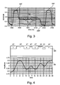
- the results are shown in figure 3 .
- the signal amplitude is much larger than for the pits and lands below the diffraction limit.
- the nineteen 2T lands of the InSb disc show a higher reflectivity with regard to the 2T pits, signal S3, corresponding with the higher reflectivity of the two 19T lands, and the twenty 2T pits between the 19T land and the 20T pit are clearly resolved.
- the twenty 2T pits of the AIST disc, signal S4 shows a worse behaviour:
- the two 19T lands show also a higher reflectivity, but the twenty 2T lands of the AgInSbTe disc show a lower reflectivity, in contrast with the twenty 2T pits of the InSb disc, signal S3. Because of the inverted signal S4 of the 2T pits, for the AgInSbTe disc only nineteen 2T pits can be resolved.
- the results are consistent with the diffractive read out of the pits, which provides a increased reflectivity for lands and an decreased reflectivity for pits, independently whether they have a size below or above the diffraction limit. Therefore, the signals of the 2T pits of the AgInSbTe super-resolution disc are inverted with regard to 20T pits, as can be seen in Fig. 3 .
- a calculated HF signal S6 is shown for a random sequence of pits and lands, graph S5, for a super-resolution disc comprising an InSb mask layer.
- the pits and lands of the graph S6 have a size from 2T to 5T as indicated, lands represented by a logical "1" and pits represented by "0".
- the simulation result, graph S6, shows clearly a lower reflection for the pits having a size above and below the diffraction limit, and show a higher reflection for lands of all sizes. Therefore, all pits can be clearly resolved and consequently detected by a pickup, when reading the data of the graph S5 arranged on a track of the InSb super-resolution disc.
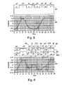
- Fig. 5 The situation for a super-resolution disc comprising an AgInSbTe mask layer as a super-resolution layer is shown in Fig. 5 :
- the graph S7 corresponds with the same pit and land sequence of graph S5 of Fig. 4 and the signal S8 shows the respective calculated HF signal for the AgInSbTe disc.
- the 5T and 3T lands have a higher amplitude corresponding with a higher reflectivity and the 4T pits have a lower amplitude corresponding with a lower reflectivity.
- the 2T pit shows a higher reflectivity and the 2T land shows a lower reflectivity, due to the inversion of the signal for pits and lands having a size below the diffraction limit, as described above, and therefore, they cannot be decoded because their signal is included in the larger pits and lands.
- the 2T pits and 2T lands included in the signal S8 cannot be resolved.
- a land having a size below the diffraction limit is inverted to a pit and enclosed by auxiliary lands, and a pit having a size below the diffraction limit is inverted to a land and enclosed by auxiliary pits.
- a group of consecutive lands, consecutive pits or consecutive pits and lands having a size below the diffraction limit for all marks of the said group is inverted to a group of pits and/or lands and enclosed by auxiliary pits or lands.
- the inversion mechanism as described before for optical storage media comprising a non-linear layer with a phase change material is compensated.
- a preferred embodiment comprising inverted pits and lands for providing a correct read-out of a phase change super-resolution optical disk is explained with regard to Fig. 6 .
- a graph S9 shows a sequence of data comprising pits and lands having a size above the diffraction limit and a 2T pit and a 2T land having a size below the diffraction limit of a corresponding optical pickup as described with regard to graphs S5 and S7 of Figs. 4 and 5 .
- the sequence of digital data S9 is encoded into another sequence of digital data S10 in accordance with the invention.
- the 2T land 2TL of graph S9 is inverted into a pit IL, which is separated from the preceding pit by an auxiliary land AL and separated from the subsequent pit by an auxiliary land AL.
- the preceding and subsequent pits two 4T pits, are correspondingly shorter and represented now by two 3T pits on graph S10. Due to the inverted read-out signal of lands having a size below the diffraction limit, the inverted land IL will produce a reflected signal with a higher amplitude corresponding with the higher amplitudes of the lands having a size above the diffraction limit, and the inverted land IL can be distinguished therefore from the preceding and following 4T pits, when reading the data of the data sequence of graph S9.
- the 2T pit 2TP is inverted to a land IP and is separated from the preceding pit by an auxiliary pit AP and separated from the subsequent land by an auxiliary pit AP.
- the preceding and subsequent pits, 3T and 5T pits, are correspondingly shorter by 1T to obtain the same data density on the optical storage medium.
- the inverted 2T pit IP will be detected as a pit when reading the data signal of graph S9, and therefore, the 2T pit between the 3T land and 5T land can be recognized and correctly decoded.
- a calculated HF data signal for the data sequence of graph S10 is shown in graph S11, which shows clearly response signals for the inverted land IL and the inverted pit IP.
- the 3T and 5T lands before and after the inverted pit IP may retain their length, also the 4T pits preceding and following the inverted land IL, but then the storage capacity of the optical storage medium would be reduced in accordance with the amount of auxiliary pits and lands used on the optical storage medium.
- the auxiliary pits AP and auxiliary lands AL have in particular a size being below the diffraction limit of the optical pickup and may be larger or even smaller than a corresponding 1T land or 1T pit.
- the 3T land of graph S9 preceding the 2T pit 2TP is shortened due to the auxiliary pit AP to a length of 2T, which falls into the super-resolution regime. Then the 3T land would not be decoded correctly because all 2T lands included in the data structure of graph S10 have to be inverted. This situation therefore has to be avoided.
- This can be done by using an appropriate modulation, which avoids for example 3T lands following or preceding a 2T pit, and avoid 3T pits following or preceding a 2T land, or by using a modulation algorithm, which does not include any 3T pits and lands. Another possibility would be to extend the 2T pits and lands to 3T pits and lands.
- the embodiment as described with regard to Fig. 6 includes 2T pits and lands having a size below the diffraction limit, and 3T pits and lands, also larger pits and lands, having a size above the diffraction limit of a corresponding optical pickup.
- the pits and lands may be designed such, that also 3T pits and lands have a size below the diffraction limit of the pickup.
- the 3T pits and lands will be inverted also on the storage medium and separated by auxiliary pits respectively lands from a preceding and/or following pit or land having a size above the diffraction limit, in correspondence with the embodiment described with regard to Fig. 6 .
- a solution to the preceding issue could be found also by adjusting the size of the auxiliary lands or pits such in order to prevent that due to the shortening of smallest diffractive marks and spaces, they fall below the limit of diffraction, keeping it readable with the diffractive read-out.
- a trade-off has to be taken in account, between the minimum applicable length of an auxiliary land or pit and the maximum available length in order to prevent the smallest diffractive mark length to fall below the diffraction limit.
- a pit follows directly a land having both a size below the diffraction limit, or several pits and lands having a size below the diffraction limit follow each other directly, then they are all correspondingly inverted according to the invention, but no auxiliary lands and auxiliary pits are required in between the lands and pits having the size below the diffraction limit.
- an auxiliary land precedes the pit representing the 2T land, which is followed by the land representing the 2T pit.
- an auxiliary pit is included, to separate the 2T land from the subsequent land, when this land has a size being above the diffraction limit. Between the inverted land and the subsequent inverted pit no auxiliary land is included.
- the optical storage medium comprising tracks having a data structure as described with regard to Fig. 6 is in particular a read-only optical disk.
- a corresponding stamper is required, on which the respective data structure is mirrored. Therefore, care has to be taken, that the small auxiliary pits and lands are clearly reproduced on the optical disk by the stamper. The size of the auxiliary pits and lands therefore has to be carefully selected.
Landscapes
- Optical Recording Or Reproduction (AREA)
- Optical Record Carriers And Manufacture Thereof (AREA)
Claims (12)
- Optisches Speichermedium, das umfasst:eine Substratschicht (2),eine Nur-Lese-Datenschicht (3), die eine Pit/Land-Datenstruktur mit Daten aufweist, die in Spuren auf der Substratschicht (2) angeordnet sind, undeine nichtlineare Schicht (4) mit einer hochauflösenden Struktur, die auf der Datenschicht (3) angeordnet ist,wobei die Datenstruktur Pits und Lands (3T-5T), die eine Größe über einer Beugungsgrenze eines Abnehmers zum Lesen der Daten aufweisen, und Pits und Lands (2T), die eine Größe unter der Beugungsgrenze aufweisen, umfasst,dadurch gekennzeichnet, dass ein Land (2TL), das eine Größe unter der Beugungsgrenze aufweist, zu einem Pit (IL) umgekehrt ist und von Hilfs-Lands (AL) eingeschlossen ist, und ein Pit (2TP), das eine Größe unter der Beugungsgrenze aufweist, zu einem Land (IP) umgekehrt ist und von Hilfs-Pits (AP) eingeschlossen ist.
- Optisches Speichermedium nach Anspruch 1,
bei dem ein Land, das einem umgekehrten Pit (IP) vorausgeht (3T), und ein Land (5T), das auf ein umgekehrtes Pit (IP) folgt, um eine Länge, die der Länge eines Hilfs-Lands (AP) entspricht, verkürzt sind, und ein Pit (3T), das einem umgekehrten Land (IL) vorangeht, und ein Pit (4T), das auf ein umgekehrtes Land (IL) folgt, um eine Länge, die der Länge eines Hilfs-Pits (AP) entspricht, verkürzt sind. - Optisches Speichermedium nach Anspruch 1 oder 2, bei dem die Hilfs-Lands (AL) und -Pits (AP) eine Größe unter der Beugungsgrenze aufweisen.
- Optisches Speichermedium nach Anspruch 3, bei dem die Hilfs-Lands (AL) eine Größe aufweisen, die einem 1T-Land entspricht, und die Hilfs-Pits (AP) eine Größe aufweisen, die einem 1T-Plt entspricht.
- Optisches Speichermedium nach einem der vorhergehenden Ansprüche, bei dem die hochauflösende Struktur ein Phasenänderungsmaterial umfasst.
- Optisches Speichermedium nach Anspruch 5, bei dem das Phasenänderungsmaterial ein Chalkogenidmaterial, z. B. GeSbTe oder AgInSbTe, ist.
- Optisches Speichermedium nach einem der vorhergehenden Ansprüche, das ferner umfasst: eine Deckschicht (7) über der nichtlinearen Schicht (4), wobei das Speichermedium für den Betrieb mit einem Laserstrahl ausgelegt ist, der zunächst die Deckschicht (7) durchdringt.
- Optisches Speichermedium nach Anspruch 7, das ferner umfasst: eine erste dielektrische Schicht (5), die zwischen der nichtlinearen Schicht (4) und der Datenschicht (3) angeordnet ist, und eine zweite dielektrische Schicht (6), die zwischen der nichtlinearen Schicht (4) und der Deckschicht (7) angeordnet ist.
- Optisches Speichermedium nach einem der vorhergehenden Ansprüche, bei dem die Pits (2TP) und die Lands (2TL) einer Spur, die eine Größe unter der Beugungsgrenze aufweisen, 2T- und/oder 3T-Pits und -Lands sind.
- Optisches Speichermedium nach einem der vorhergehenden Ansprüche, bei dem die Beugungsgrenze des Abnehmers zum Lesen der Daten als Lambda/4NA definiert ist, wobei Lambda eine Laserwellenlänge ist und NA eine numerische Apertur des Abnehmers ist.
- Optisches Speichermedium nach einem der vorhergehenden Ansprüche, dadurch gekennzeichnet, dass zwischen einem umgekehrten Land und einem nachfolgenden umgekehrten Pit und zwischen einer umgekehrten Pit und einem nachfolgenden umgekehrten Land kein Hilfs-Land oder Hilfs-Pit enthalten ist.
- Optisches Speichermedium nach einem der vorhergehenden Ansprüche 1-10, bei dem ein umgekehrtes Land (IL) von dem vorhergehenden Pit durch ein Hilfs-Land (AL) getrennt ist und von dem nachfolgenden Pit durch ein Hilfs-Land (AL) getrennt ist, und bei dem ein umgekehrtes Pit (IP) von dem vorhergehenden Land durch ein Hilfs-Pit (AP) getrennt ist und von dem nachfolgenden Land durch ein Hilfs-Pit (AP) getrennt ist.
Priority Applications (1)
| Application Number | Priority Date | Filing Date | Title |
|---|---|---|---|
| EP09717740A EP2260490B1 (de) | 2008-03-07 | 2009-03-06 | Optisches speichermedium mit umgekehrten hochauflösenden höhen und tiefen |
Applications Claiming Priority (3)
| Application Number | Priority Date | Filing Date | Title |
|---|---|---|---|
| EP08102389 | 2008-03-07 | ||
| PCT/EP2009/052659 WO2009109653A1 (en) | 2008-03-07 | 2009-03-06 | Optical storage medium comprising inverted super-resolution pits and lands |
| EP09717740A EP2260490B1 (de) | 2008-03-07 | 2009-03-06 | Optisches speichermedium mit umgekehrten hochauflösenden höhen und tiefen |
Publications (2)
| Publication Number | Publication Date |
|---|---|
| EP2260490A1 EP2260490A1 (de) | 2010-12-15 |
| EP2260490B1 true EP2260490B1 (de) | 2011-11-02 |
Family
ID=40521709
Family Applications (1)
| Application Number | Title | Priority Date | Filing Date |
|---|---|---|---|
| EP09717740A Not-in-force EP2260490B1 (de) | 2008-03-07 | 2009-03-06 | Optisches speichermedium mit umgekehrten hochauflösenden höhen und tiefen |
Country Status (7)
| Country | Link |
|---|---|
| US (1) | US8072872B2 (de) |
| EP (1) | EP2260490B1 (de) |
| JP (1) | JP5314054B2 (de) |
| KR (1) | KR101554054B1 (de) |
| CN (1) | CN101960521B (de) |
| AT (1) | ATE532180T1 (de) |
| WO (1) | WO2009109653A1 (de) |
Families Citing this family (5)
| Publication number | Priority date | Publication date | Assignee | Title |
|---|---|---|---|---|
| EP2299442A1 (de) * | 2009-09-17 | 2011-03-23 | Thomson Licensing | Optisches Speichermedium mit einer Datenschicht mit invertierter Vertiefungs-/Erhebungsdatenstruktur |
| EP2372709A1 (de) | 2010-03-30 | 2011-10-05 | Thomson Licensing | Optisches Speichermedium mit einer Datenschicht mit reduziertem Spurabstand und einer invertierten/nichtinvertierten Impuls-/Tastdatenstruktur |
| EP2381441A1 (de) * | 2010-04-21 | 2011-10-26 | Thomson Licensing | Optische Platte mit Schutzcode, Verfahren zum Erhalten des Schutzcodes und entsprechendes Datenlesegerät |
| EP2385524A1 (de) | 2010-05-07 | 2011-11-09 | Thomson Licensing | Optische Platte mit verbesserter Empfindlichkeit für hochauflösende Höhen und Tiefen |
| US8588049B2 (en) * | 2010-05-10 | 2013-11-19 | Thomson Licensing | Optical storage medium comprising a phase shift compensation |
Family Cites Families (14)
| Publication number | Priority date | Publication date | Assignee | Title |
|---|---|---|---|---|
| JP3866016B2 (ja) * | 1999-07-02 | 2007-01-10 | Tdk株式会社 | 光情報媒体およびその再生方法 |
| JP4251527B2 (ja) * | 2001-10-15 | 2009-04-08 | 独立行政法人産業技術総合研究所 | 光情報媒体の再生方法および再生装置 |
| JP4582755B2 (ja) * | 2002-06-24 | 2010-11-17 | Tdk株式会社 | 光記録/再生方法および光記録媒体 |
| JP2004227622A (ja) * | 2003-01-20 | 2004-08-12 | Toshiba Corp | 光記録媒体および光記録再生方法 |
| KR20050029765A (ko) * | 2003-09-22 | 2005-03-28 | 삼성전자주식회사 | 고밀도 재생전용 광디스크 및 그 제조방법 |
| US7232598B2 (en) * | 2003-10-22 | 2007-06-19 | Lg Electronics Inc. | Super resolution optical disc |
| JP4253725B2 (ja) * | 2003-10-31 | 2009-04-15 | 独立行政法人産業技術総合研究所 | データ再生方法およびデータ記録再生装置 |
| US20050157631A1 (en) * | 2003-12-30 | 2005-07-21 | Samsung Electronics Co., Ltd | Information storage medium and method and apparatus for reproducing information recorded on the same |
| JP4327045B2 (ja) * | 2004-08-23 | 2009-09-09 | 株式会社日立製作所 | 情報再生方法及び情報記録媒体 |
| JP4285451B2 (ja) * | 2005-07-06 | 2009-06-24 | 株式会社日立製作所 | 情報記録媒体、情報再生方法及び情報記録方法 |
| JP2007048352A (ja) * | 2005-08-08 | 2007-02-22 | Tdk Corp | 光記録媒体及び光記録媒体の情報再生方法 |
| JP4835096B2 (ja) * | 2005-10-07 | 2011-12-14 | Tdk株式会社 | 超解像光記録媒体及び超解像光記録媒体への情報記録方法 |
| JP2007172701A (ja) * | 2005-12-20 | 2007-07-05 | Tdk Corp | 超解像光記録媒体及び超解像光記録媒体への情報記録方法 |
| JP4705530B2 (ja) * | 2006-08-07 | 2011-06-22 | 株式会社リコー | 光記録媒体とその基板、及び該基板の成形用スタンパ |
-
2009
- 2009-03-06 EP EP09717740A patent/EP2260490B1/de not_active Not-in-force
- 2009-03-06 US US12/736,072 patent/US8072872B2/en not_active Expired - Fee Related
- 2009-03-06 WO PCT/EP2009/052659 patent/WO2009109653A1/en not_active Ceased
- 2009-03-06 CN CN2009801079751A patent/CN101960521B/zh not_active Expired - Fee Related
- 2009-03-06 KR KR1020107022327A patent/KR101554054B1/ko not_active Expired - Fee Related
- 2009-03-06 AT AT09717740T patent/ATE532180T1/de active
- 2009-03-06 JP JP2010549158A patent/JP5314054B2/ja not_active Expired - Fee Related
Also Published As
| Publication number | Publication date |
|---|---|
| JP2011514612A (ja) | 2011-05-06 |
| CN101960521B (zh) | 2012-07-18 |
| KR20100127816A (ko) | 2010-12-06 |
| EP2260490A1 (de) | 2010-12-15 |
| US8072872B2 (en) | 2011-12-06 |
| JP5314054B2 (ja) | 2013-10-16 |
| ATE532180T1 (de) | 2011-11-15 |
| US20110038248A1 (en) | 2011-02-17 |
| CN101960521A (zh) | 2011-01-26 |
| WO2009109653A1 (en) | 2009-09-11 |
| KR101554054B1 (ko) | 2015-09-17 |
Similar Documents
| Publication | Publication Date | Title |
|---|---|---|
| EP2260489B1 (de) | Optisches speichermedium mit mehrstufiger datenschicht | |
| US8072872B2 (en) | Optical storage medium comprising inverted super-resolution pits and lands | |
| EP2569768B1 (de) | Optisches speichermedium mit phasenumtastung | |
| CN101903949B (zh) | 一种包括半导体层的可记录光存储介质及其制造方法 | |
| EP2106609B1 (de) | Optisches speichermedium mit maskenschicht für hochauflösenden nahfeldeffekt und entsprechendes herstellungsverfahren | |
| EP2109104A1 (de) | Optisches Speichermedium mit zwei Halbleiterschichten als Maskenschichten | |
| EP2299442A1 (de) | Optisches Speichermedium mit einer Datenschicht mit invertierter Vertiefungs-/Erhebungsdatenstruktur | |
| US8611202B2 (en) | Optical storage medium comprising two nonlinear layers | |
| US8611196B2 (en) | Method applying a pulsed laser beam for reading of an optical disc and respective apparatus | |
| US8264925B2 (en) | Optical disc with protection code, method for obtaining the protection code and respective apparatus for reading of data | |
| US8599676B2 (en) | Optical disc with improved sensitivity for super-resolution pits and lands | |
| EP2372709A1 (de) | Optisches Speichermedium mit einer Datenschicht mit reduziertem Spurabstand und einer invertierten/nichtinvertierten Impuls-/Tastdatenstruktur | |
| EP2325840A1 (de) | Optisches Speichermedium mit einer aktiven Schicht als nichtreflektierende Schicht | |
| EP2346040A1 (de) | Optisches Speichermedium mit einer hochauflösenden Schicht und einer schreibgeschützten Datenschicht | |
| WO2009147048A1 (en) | Optical storage medium comprising a recordable data layer with a non-linear structure and respective recorder |
Legal Events
| Date | Code | Title | Description |
|---|---|---|---|
| PUAI | Public reference made under article 153(3) epc to a published international application that has entered the european phase |
Free format text: ORIGINAL CODE: 0009012 |
|
| 17P | Request for examination filed |
Effective date: 20100806 |
|
| AK | Designated contracting states |
Kind code of ref document: A1 Designated state(s): AT BE BG CH CY CZ DE DK EE ES FI FR GB GR HR HU IE IS IT LI LT LU LV MC MK MT NL NO PL PT RO SE SI SK TR |
|
| AX | Request for extension of the european patent |
Extension state: AL BA RS |
|
| GRAP | Despatch of communication of intention to grant a patent |
Free format text: ORIGINAL CODE: EPIDOSNIGR1 |
|
| DAX | Request for extension of the european patent (deleted) | ||
| GRAS | Grant fee paid |
Free format text: ORIGINAL CODE: EPIDOSNIGR3 |
|
| GRAA | (expected) grant |
Free format text: ORIGINAL CODE: 0009210 |
|
| REG | Reference to a national code |
Ref legal event code: R084 Ref document number: 602009003445 Country of ref document: DE Ref country code: DE |
|
| AK | Designated contracting states |
Kind code of ref document: B1 Designated state(s): AT BE BG CH CY CZ DE DK EE ES FI FR GB GR HR HU IE IS IT LI LT LU LV MC MK MT NL NO PL PT RO SE SI SK TR |
|
| REG | Reference to a national code |
Ref country code: GB Ref legal event code: FG4D |
|
| REG | Reference to a national code |
Ref country code: CH Ref legal event code: EP |
|
| REG | Reference to a national code |
Ref country code: GB Ref legal event code: 746 Effective date: 20111025 |
|
| REG | Reference to a national code |
Ref country code: IE Ref legal event code: FG4D |
|
| REG | Reference to a national code |
Ref country code: DE Ref legal event code: R084 Ref document number: 602009003445 Country of ref document: DE Effective date: 20111021 |
|
| REG | Reference to a national code |
Ref country code: DE Ref legal event code: R096 Ref document number: 602009003445 Country of ref document: DE Effective date: 20111229 |
|
| REG | Reference to a national code |
Ref country code: NL Ref legal event code: VDEP Effective date: 20111102 |
|
| LTIE | Lt: invalidation of european patent or patent extension |
Effective date: 20111102 |
|
| PG25 | Lapsed in a contracting state [announced via postgrant information from national office to epo] |
Ref country code: IS Free format text: LAPSE BECAUSE OF FAILURE TO SUBMIT A TRANSLATION OF THE DESCRIPTION OR TO PAY THE FEE WITHIN THE PRESCRIBED TIME-LIMIT Effective date: 20120302 Ref country code: LT Free format text: LAPSE BECAUSE OF FAILURE TO SUBMIT A TRANSLATION OF THE DESCRIPTION OR TO PAY THE FEE WITHIN THE PRESCRIBED TIME-LIMIT Effective date: 20111102 Ref country code: NO Free format text: LAPSE BECAUSE OF FAILURE TO SUBMIT A TRANSLATION OF THE DESCRIPTION OR TO PAY THE FEE WITHIN THE PRESCRIBED TIME-LIMIT Effective date: 20120202 |
|
| PG25 | Lapsed in a contracting state [announced via postgrant information from national office to epo] |
Ref country code: GR Free format text: LAPSE BECAUSE OF FAILURE TO SUBMIT A TRANSLATION OF THE DESCRIPTION OR TO PAY THE FEE WITHIN THE PRESCRIBED TIME-LIMIT Effective date: 20120203 Ref country code: PL Free format text: LAPSE BECAUSE OF FAILURE TO SUBMIT A TRANSLATION OF THE DESCRIPTION OR TO PAY THE FEE WITHIN THE PRESCRIBED TIME-LIMIT Effective date: 20111102 Ref country code: SE Free format text: LAPSE BECAUSE OF FAILURE TO SUBMIT A TRANSLATION OF THE DESCRIPTION OR TO PAY THE FEE WITHIN THE PRESCRIBED TIME-LIMIT Effective date: 20111102 Ref country code: BE Free format text: LAPSE BECAUSE OF FAILURE TO SUBMIT A TRANSLATION OF THE DESCRIPTION OR TO PAY THE FEE WITHIN THE PRESCRIBED TIME-LIMIT Effective date: 20111102 Ref country code: SI Free format text: LAPSE BECAUSE OF FAILURE TO SUBMIT A TRANSLATION OF THE DESCRIPTION OR TO PAY THE FEE WITHIN THE PRESCRIBED TIME-LIMIT Effective date: 20111102 Ref country code: HR Free format text: LAPSE BECAUSE OF FAILURE TO SUBMIT A TRANSLATION OF THE DESCRIPTION OR TO PAY THE FEE WITHIN THE PRESCRIBED TIME-LIMIT Effective date: 20111102 Ref country code: LV Free format text: LAPSE BECAUSE OF FAILURE TO SUBMIT A TRANSLATION OF THE DESCRIPTION OR TO PAY THE FEE WITHIN THE PRESCRIBED TIME-LIMIT Effective date: 20111102 Ref country code: NL Free format text: LAPSE BECAUSE OF FAILURE TO SUBMIT A TRANSLATION OF THE DESCRIPTION OR TO PAY THE FEE WITHIN THE PRESCRIBED TIME-LIMIT Effective date: 20111102 Ref country code: PT Free format text: LAPSE BECAUSE OF FAILURE TO SUBMIT A TRANSLATION OF THE DESCRIPTION OR TO PAY THE FEE WITHIN THE PRESCRIBED TIME-LIMIT Effective date: 20120302 |
|
| PG25 | Lapsed in a contracting state [announced via postgrant information from national office to epo] |
Ref country code: CY Free format text: LAPSE BECAUSE OF FAILURE TO SUBMIT A TRANSLATION OF THE DESCRIPTION OR TO PAY THE FEE WITHIN THE PRESCRIBED TIME-LIMIT Effective date: 20111102 |
|
| PG25 | Lapsed in a contracting state [announced via postgrant information from national office to epo] |
Ref country code: BG Free format text: LAPSE BECAUSE OF FAILURE TO SUBMIT A TRANSLATION OF THE DESCRIPTION OR TO PAY THE FEE WITHIN THE PRESCRIBED TIME-LIMIT Effective date: 20120202 Ref country code: DK Free format text: LAPSE BECAUSE OF FAILURE TO SUBMIT A TRANSLATION OF THE DESCRIPTION OR TO PAY THE FEE WITHIN THE PRESCRIBED TIME-LIMIT Effective date: 20111102 Ref country code: CZ Free format text: LAPSE BECAUSE OF FAILURE TO SUBMIT A TRANSLATION OF THE DESCRIPTION OR TO PAY THE FEE WITHIN THE PRESCRIBED TIME-LIMIT Effective date: 20111102 Ref country code: EE Free format text: LAPSE BECAUSE OF FAILURE TO SUBMIT A TRANSLATION OF THE DESCRIPTION OR TO PAY THE FEE WITHIN THE PRESCRIBED TIME-LIMIT Effective date: 20111102 Ref country code: SK Free format text: LAPSE BECAUSE OF FAILURE TO SUBMIT A TRANSLATION OF THE DESCRIPTION OR TO PAY THE FEE WITHIN THE PRESCRIBED TIME-LIMIT Effective date: 20111102 |
|
| PG25 | Lapsed in a contracting state [announced via postgrant information from national office to epo] |
Ref country code: IT Free format text: LAPSE BECAUSE OF FAILURE TO SUBMIT A TRANSLATION OF THE DESCRIPTION OR TO PAY THE FEE WITHIN THE PRESCRIBED TIME-LIMIT Effective date: 20111102 Ref country code: RO Free format text: LAPSE BECAUSE OF FAILURE TO SUBMIT A TRANSLATION OF THE DESCRIPTION OR TO PAY THE FEE WITHIN THE PRESCRIBED TIME-LIMIT Effective date: 20111102 |
|
| PLBE | No opposition filed within time limit |
Free format text: ORIGINAL CODE: 0009261 |
|
| STAA | Information on the status of an ep patent application or granted ep patent |
Free format text: STATUS: NO OPPOSITION FILED WITHIN TIME LIMIT |
|
| REG | Reference to a national code |
Ref country code: AT Ref legal event code: MK05 Ref document number: 532180 Country of ref document: AT Kind code of ref document: T Effective date: 20111102 |
|
| 26N | No opposition filed |
Effective date: 20120803 |
|
| PG25 | Lapsed in a contracting state [announced via postgrant information from national office to epo] |
Ref country code: MC Free format text: LAPSE BECAUSE OF NON-PAYMENT OF DUE FEES Effective date: 20120331 |
|
| REG | Reference to a national code |
Ref country code: DE Ref legal event code: R097 Ref document number: 602009003445 Country of ref document: DE Effective date: 20120803 |
|
| REG | Reference to a national code |
Ref country code: IE Ref legal event code: MM4A |
|
| PG25 | Lapsed in a contracting state [announced via postgrant information from national office to epo] |
Ref country code: IE Free format text: LAPSE BECAUSE OF NON-PAYMENT OF DUE FEES Effective date: 20120306 Ref country code: AT Free format text: LAPSE BECAUSE OF FAILURE TO SUBMIT A TRANSLATION OF THE DESCRIPTION OR TO PAY THE FEE WITHIN THE PRESCRIBED TIME-LIMIT Effective date: 20111102 |
|
| PG25 | Lapsed in a contracting state [announced via postgrant information from national office to epo] |
Ref country code: MK Free format text: LAPSE BECAUSE OF FAILURE TO SUBMIT A TRANSLATION OF THE DESCRIPTION OR TO PAY THE FEE WITHIN THE PRESCRIBED TIME-LIMIT Effective date: 20111102 |
|
| PG25 | Lapsed in a contracting state [announced via postgrant information from national office to epo] |
Ref country code: ES Free format text: LAPSE BECAUSE OF FAILURE TO SUBMIT A TRANSLATION OF THE DESCRIPTION OR TO PAY THE FEE WITHIN THE PRESCRIBED TIME-LIMIT Effective date: 20120213 |
|
| PG25 | Lapsed in a contracting state [announced via postgrant information from national office to epo] |
Ref country code: FI Free format text: LAPSE BECAUSE OF FAILURE TO SUBMIT A TRANSLATION OF THE DESCRIPTION OR TO PAY THE FEE WITHIN THE PRESCRIBED TIME-LIMIT Effective date: 20111102 |
|
| PG25 | Lapsed in a contracting state [announced via postgrant information from national office to epo] |
Ref country code: MT Free format text: LAPSE BECAUSE OF FAILURE TO SUBMIT A TRANSLATION OF THE DESCRIPTION OR TO PAY THE FEE WITHIN THE PRESCRIBED TIME-LIMIT Effective date: 20111102 |
|
| REG | Reference to a national code |
Ref country code: CH Ref legal event code: PL |
|
| PG25 | Lapsed in a contracting state [announced via postgrant information from national office to epo] |
Ref country code: LI Free format text: LAPSE BECAUSE OF NON-PAYMENT OF DUE FEES Effective date: 20130331 Ref country code: CH Free format text: LAPSE BECAUSE OF NON-PAYMENT OF DUE FEES Effective date: 20130331 |
|
| PG25 | Lapsed in a contracting state [announced via postgrant information from national office to epo] |
Ref country code: TR Free format text: LAPSE BECAUSE OF FAILURE TO SUBMIT A TRANSLATION OF THE DESCRIPTION OR TO PAY THE FEE WITHIN THE PRESCRIBED TIME-LIMIT Effective date: 20111102 |
|
| PG25 | Lapsed in a contracting state [announced via postgrant information from national office to epo] |
Ref country code: LU Free format text: LAPSE BECAUSE OF NON-PAYMENT OF DUE FEES Effective date: 20120306 |
|
| PG25 | Lapsed in a contracting state [announced via postgrant information from national office to epo] |
Ref country code: HU Free format text: LAPSE BECAUSE OF FAILURE TO SUBMIT A TRANSLATION OF THE DESCRIPTION OR TO PAY THE FEE WITHIN THE PRESCRIBED TIME-LIMIT Effective date: 20090306 |
|
| REG | Reference to a national code |
Ref country code: FR Ref legal event code: PLFP Year of fee payment: 8 |
|
| PGFP | Annual fee paid to national office [announced via postgrant information from national office to epo] |
Ref country code: DE Payment date: 20160324 Year of fee payment: 8 |
|
| PGFP | Annual fee paid to national office [announced via postgrant information from national office to epo] |
Ref country code: FR Payment date: 20160324 Year of fee payment: 8 Ref country code: GB Payment date: 20160324 Year of fee payment: 8 |
|
| REG | Reference to a national code |
Ref country code: DE Ref legal event code: R119 Ref document number: 602009003445 Country of ref document: DE |
|
| GBPC | Gb: european patent ceased through non-payment of renewal fee |
Effective date: 20170306 |
|
| REG | Reference to a national code |
Ref country code: FR Ref legal event code: ST Effective date: 20171130 |
|
| PG25 | Lapsed in a contracting state [announced via postgrant information from national office to epo] |
Ref country code: FR Free format text: LAPSE BECAUSE OF NON-PAYMENT OF DUE FEES Effective date: 20170331 Ref country code: DE Free format text: LAPSE BECAUSE OF NON-PAYMENT OF DUE FEES Effective date: 20171003 |
|
| PG25 | Lapsed in a contracting state [announced via postgrant information from national office to epo] |
Ref country code: GB Free format text: LAPSE BECAUSE OF NON-PAYMENT OF DUE FEES Effective date: 20170306 |