EP2385524A1 - Optische Platte mit verbesserter Empfindlichkeit für hochauflösende Höhen und Tiefen - Google Patents
Optische Platte mit verbesserter Empfindlichkeit für hochauflösende Höhen und Tiefen Download PDFInfo
- Publication number
- EP2385524A1 EP2385524A1 EP10305482A EP10305482A EP2385524A1 EP 2385524 A1 EP2385524 A1 EP 2385524A1 EP 10305482 A EP10305482 A EP 10305482A EP 10305482 A EP10305482 A EP 10305482A EP 2385524 A1 EP2385524 A1 EP 2385524A1
- Authority
- EP
- European Patent Office
- Prior art keywords
- resolution
- super
- pit
- land
- diffractive
- Prior art date
- Legal status (The legal status is an assumption and is not a legal conclusion. Google has not performed a legal analysis and makes no representation as to the accuracy of the status listed.)
- Withdrawn
Links
Images


Classifications
-
- G—PHYSICS
- G11—INFORMATION STORAGE
- G11B—INFORMATION STORAGE BASED ON RELATIVE MOVEMENT BETWEEN RECORD CARRIER AND TRANSDUCER
- G11B7/00—Recording or reproducing by optical means, e.g. recording using a thermal beam of optical radiation by modifying optical properties or the physical structure, reproducing using an optical beam at lower power by sensing optical properties; Record carriers therefor
- G11B7/24—Record carriers characterised by shape, structure or physical properties, or by the selection of the material
- G11B7/241—Record carriers characterised by shape, structure or physical properties, or by the selection of the material characterised by the selection of the material
- G11B7/252—Record carriers characterised by shape, structure or physical properties, or by the selection of the material characterised by the selection of the material of layers other than recording layers
-
- G—PHYSICS
- G11—INFORMATION STORAGE
- G11B—INFORMATION STORAGE BASED ON RELATIVE MOVEMENT BETWEEN RECORD CARRIER AND TRANSDUCER
- G11B7/00—Recording or reproducing by optical means, e.g. recording using a thermal beam of optical radiation by modifying optical properties or the physical structure, reproducing using an optical beam at lower power by sensing optical properties; Record carriers therefor
- G11B7/24—Record carriers characterised by shape, structure or physical properties, or by the selection of the material
- G11B7/2407—Tracks or pits; Shape, structure or physical properties thereof
- G11B7/24085—Pits
-
- G—PHYSICS
- G11—INFORMATION STORAGE
- G11B—INFORMATION STORAGE BASED ON RELATIVE MOVEMENT BETWEEN RECORD CARRIER AND TRANSDUCER
- G11B7/00—Recording or reproducing by optical means, e.g. recording using a thermal beam of optical radiation by modifying optical properties or the physical structure, reproducing using an optical beam at lower power by sensing optical properties; Record carriers therefor
- G11B7/24—Record carriers characterised by shape, structure or physical properties, or by the selection of the material
- G11B7/2403—Layers; Shape, structure or physical properties thereof
- G11B7/24065—Layers assisting in recording or reproduction below the optical diffraction limit, e.g. non-linear optical layers or structures
-
- G—PHYSICS
- G11—INFORMATION STORAGE
- G11B—INFORMATION STORAGE BASED ON RELATIVE MOVEMENT BETWEEN RECORD CARRIER AND TRANSDUCER
- G11B7/00—Recording or reproducing by optical means, e.g. recording using a thermal beam of optical radiation by modifying optical properties or the physical structure, reproducing using an optical beam at lower power by sensing optical properties; Record carriers therefor
- G11B7/24—Record carriers characterised by shape, structure or physical properties, or by the selection of the material
- G11B7/241—Record carriers characterised by shape, structure or physical properties, or by the selection of the material characterised by the selection of the material
- G11B7/252—Record carriers characterised by shape, structure or physical properties, or by the selection of the material characterised by the selection of the material of layers other than recording layers
- G11B7/258—Record carriers characterised by shape, structure or physical properties, or by the selection of the material characterised by the selection of the material of layers other than recording layers of reflective layers
- G11B7/2585—Record carriers characterised by shape, structure or physical properties, or by the selection of the material characterised by the selection of the material of layers other than recording layers of reflective layers based on aluminium
Definitions
- the present invention relates to an optical storage medium comprising a substrate layer, a data layer and a nonlinear layer with a super-resolution structure arranged above the data layer.
- the data layer comprises in particular pits and lands having a size above an optical resolution limit and pits and lands having a size below the optical resolution limit of a pickup for reading of the data being arranged on the data layer.
- Optical storage media are media in which data are stored in an optically readable manner, for example by means of a laser and an optical detector, for example a photodetector, being integrated within a pickup.
- the detector is used for detecting reflected light of the laser beam when reading data on the storage medium.
- optical storage media which are operated with different laser wavelength, and which have different sizes for providing storage capacities from below one Gigabyte up to 50 Gigabyte (GB).
- the formats include read-only formats such as Audio CD and Video DVD, write-once optical media such as CD-R and DVD-R, DVD+R, as well as rewritable formats like CD-RW, DVD-RW and DVD+RW. Digital data are stored on these media along tracks in one or more layers of the media.
- the storage medium with the highest data capacity is at present the Blu-Ray disc (BD), which allows to store up to about 50 GB on a dual layer disc.
- BD Blu-Ray disc
- On the Blu-Ray disc a track pitch of 320 nm and a mark length from 2T to 8T or 9T is used, where T is the channel bit length and wherein 2T corresponds with a minimum mark length of 138, 149 or 160 nm.
- This theoretical minimal detectable length from the diffraction theory is corresponding to a period of the pattern function, which is formed of a pit and of a land having the same length.
- the smallest detectable element of such a system is a pit or a land having a length of about lambda/4NA, which corresponds for a Blu-Ray type pickup with a length of 120nm.
- New optical storage media with a super-resolution structure offer the possibility to increase the data density of the optical storage medium by a factor of two to four in one dimension as compared with the Blu-Ray disc.
- This is possible by including a nonlinear layer, which is placed above a data layer of the optical storage medium, and which significantly reduces the effective size of a light spot used for reading from or writing to the optical storage medium.
- the nonlinear layer can be understood as a mask layer because it is arranged above the data layer and for some specific materials only the high intensity center part of a laser beam can penetrate the mask layer.
- semiconductor materials can be used as a nonlinear layer, e.g.
- the nonlinear layer is often called a super-resolution near-field structure (Super-RENS) layer because it is assumed that for some specific materials, the optical effect of reducing the effective spot size of the laser beam is based on a near-field interaction between the marks and spaces of the data layer and the nonlinear layer.
- Super-RENS optical discs comprising a super-resolution near-field structure formed of a metal oxide, a polymer compound or a phase-change layer comprising GeSbTe or AgInSbTe are known.
- an optical storage medium comprising a read-only data layer having a non-inverse pit/land data structure with concave pits corresponding with holes and an optical storage medium comprising a read-only data layer having an inverse pit/land data structure with convex pits corresponding with bumps on a substrate layer.
- the optical disc comprises a substrate layer, a read only data layer having a pit/land data structure arranged in tracks on the substrate layer and a nonlinear layer with a super-resolution structure disposed on the substrate layer, wherein the pit/land data structure has an average pit width and a super-resolution pit following a diffractive land is enlarged in width with regard to the average pit width, and/or a super-resolution pit following a super-resolution land and a preceding diffractive pit is enlarged in width with regard to the average pit width, and/or a diffractive pit preceding a super-resolution land is reduced in pit width with regard to the average pit width.
- the detectability of the super-resolution pits and lands is therefore increased for cases, when a large land or a large pit is preceding a super-resolution pit or a super-resolution land, which may lead to the situation, that the small signal of the super-resolution pit or super-resolution land is embedded in the large signal of a large preceding pit or land.
- a diffractive pit preceding a super-resolution land and a subsequent super-resolution pit is reduced in pit width with regard to the average pit width.
- the end of a diffractive pit preceding a super-resolution land is provided advantageously as an inclined plane, or at least the end of a diffractive pit preceding a super-resolution land and a subsequent super-resolution pit is provided as an inclined plane.
- the beginning of a super-resolution pit following a diffractive land is provided as an inclined plane to extend the effective length of the super-resolution pit. Also, it may be advantageous to enlarge all super-resolution pits in width with regard to the average pit width.
- the nonlinear layer comprises a semiconductor material as a super-resolution structure, and the pits are represented as depressions in the data layer.
- the nonlinear layer comprises a phase change material as a super-resolution structure, and the pits are represented as protrusions on the data layer.
- Fig. 1 an optical storage medium 1 is shown in a cross section in a simplified manner.
- the optical storage medium 1 is in particular a read-only (ROM) optical storage disc.
- a data layer 3 is arranged which may comprise a reflective metallic layer, for example an aluminum layer.
- the data layer 3 has a data structure consisting of marks and spaces arranged on essentially parallel tracks.
- the marks and spaces consist of pits and lands, the pits being molded or embossed on the surface of substrate 2 for representing the data layer 3.
- a first dielectric layer 5 is arranged and on the dielectric layer 5 a nonlinear layer 4 is arranged for providing the function of a mask layer for utilizing a super-resolution effect.
- the nonlinear layer 4 comprises in particular a super-resolution structure for providing the super-resolution effect, e.g. a super-resolution near-field structure (Super-RENS).
- Super-RENS super-resolution near-field structure
- a second dielectric layer 6 is disposed above the nonlinear layer 4 .
- a cover layer 7 is disposed on the second dielectric layer 5 as a protective layer.
- the optical storage medium 1 is in particular an optical disc having outside dimensions similar to DVDs and CDs.
- the first and second dielectric layers 5, 6 comprise for example the material ZnS-SiO 2 .
- the substrate 2 and the cover layer 7 may consist of a plastic material, as known from DVDs and CDs.
- the layers of the storage medium 1 are arranged particularly as a layer stack.
- the nonlinear layer 4 comprises for example a semiconductor material of the III-V semiconductor family, e.g. GaSb, InAs or InSb, or a phase-change material, for example a chalcogenide material, as the super-resolution structure.
- a semiconductor material of the III-V semiconductor family e.g. GaSb, InAs or InSb
- phase-change material for example a chalcogenide material
- the super-resolution effect allows detecting pits, which have a size, in particular a length, which is below the optical resolution limit of a corresponding apparatus for reading of the data of the optical storage medium. It has been demonstrated that the super-resolution detection of an optical disc comprising a phase-change material, also other materials like semiconductor materials, is related to a local change of the optical properties of the nonlinear layer 4.
- the optical resolution limit of a pickup for reading data of the optical storage medium can be defined as lambda/4NA, wherein lambda is the laser wavelength of the pickup and NA the numerical aperture of the pickup.
- the pits and lands of the optical storage medium having a size below the optical resolution limit are in particular 2T and 3T pits and lands, or 2T pits and lands, depending on the data density of the optical storage medium, wherein T is the channel bit length.
- 2T and/or 3T pits and lands having a length being below the optical resolution limit of the pickup will be called in this context super-resolution pits and lands, because they can be detected only by using a super-resolution effect.
- 5T-8T pits and lands have a length being above the resolution limit of the pickup are called in this context diffractive pits and lands, because for the detection a diffractive effect is effective, as known e.g. from Blu-Ray discs.
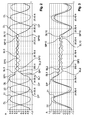
- Graph 21 of fig. 2 shows detection of a data sequence of alternatingly 10 pits SP1-SP10 and 10 lands SL1-SL10 having a length of each 80nm, which are preceded by a 400nm diffractive land DL and followed by a 400nm diffractive pit DP. Shown is the amplitude A as a function of time t. The laser power is 2,8mW.
- the data structure is arranged on an optical disc comprising a nonlinear layer provided by an InSb layer as the super-resolution structure. As can be seen, the first super-resolution pit SP1 following the diffractive land DF is clearly resolved, also the following sequence of super-resolution pits and lands. After the last super-resolution land SL10 follows the diffractive pit DP of length 400nm, after which follows a diffractive land DL of same size.
- the sequence of the 10 super-resolution pits and lands begins with a super-resolution land SL1, after a preceding diffractive pit DP.
- the sequence of the 10 super-resolution pits and lands ends correspondingly with a super-resolution pit SP10 followed by a diffractive land DL.
- the data signal obtained with the pickup when reading the data in reverse direction, graph 22, is displayed in Fig. 2 in correspondence with the data signal of graph 21.
- the signal amplitude is rising because super-resolution land SL1 is following, but the subsequent super-resolution pit SP1 is not resolved. Only the next super-resolution land SL2 is resolved, also the subsequent super-resolution pits and lands.
- graph 22 is mirrored with regard to the amplitude and displayed together with graph 21, so that the signal of the pits and lands of graph 21 correspond with the signals of graph 22.
- Graph 22 of Fig. 3 confirms that the first super-resolution pit and first super-resolution land following a large diffractive pit are not detected by the pickup.
- Super-resolution land SL2 and super-resolution pit SP2 are detected, also the subsequent super-resolution pits SP3-SP10 and super-resolution lands SL3-SL10.
- Fig. 4 shows the resolution R of pits as a function of the pit length L.
- the resolution is defined in this context as the amplitude of a pit of a given length, divided by the amplitude of a pit having a length of 600nm.
- Investigated are pits beginning with a smallest pit length of 100mn and including pits with stepwise increasing pit length of 50nm up to the largest pit length of 600nm.
- the pits are arranged on a super-resolution optical disc comprising InSb as the super-resolution material of the nonlinear layer.
- Graph 41 shows the resolution of the pits obtained when using a laser power of 0,8mW, which is not sufficient for providing a super-resolution effect of the nonlinear layer.
- Graph 42 shows the resolution of the same pits when using a laser power of 1,8mW, which is sufficient for providing a super-resolution effect.
- the super-resolution effect is not only effective below the pit length of 150nm, which is about the resolution limit of the pickup, but also for larger pit lengths.
- the resolution R is very small in comparison with the larger pits, even for the laser power of 1,8mW, and therefore the amplitude of the data signals obtained for super-resolution pits and lands of 100nm length or below is correspondingly very small.
- the resolution limit of this pickup is due to the diffraction theory correspondingly about 120nm mark length, mark length being referred here to the length of a land or a pit.
- Graph 51 shows a sequence of 10 super-resolution pits and 10 super-resolution lands, arranged between a preceding diffractive land DL and followed by a diffractive pit DP, similar to graph 21 of Figs. 2 and 3 .
- the length of the super-resolution pits and lands is each 100nm and the length of the diffractive pits and lands is each 400nm.
- Graph 52 of Fig. 5 shows the data signal for these pits and lands, but using a reverse rotation of the optical disc.
- the first super-resolution land and first super-resolution pit following the diffractive pit DP are not resolved during data reading in reverse direction, but only the subsequent super-resolution pits and lands, in agreement with Fig. 2 .
- Indicated in Fig. 5 is in addition the size DPS of the diffractive pits and the size SPS of the super-resolution pits.
- the corresponding reflectivity for the pits and lands is indicated by arrows, as originating from the diffractive effect and the super-resolution effect.
- the first diffractive pit DP, graph 51 provides a low reflectivity 10 and the subsequent diffractive land DL a high reflectivity 11.
- the diffractive land DL For the diffractive land DL, also reflectivity 12 is shown, provided in addition by the super-resolution effect, in accordance with Fig. 4 .
- the super-resolution lands have also a higher reflectivity 13 and the super-resolution pits have a lower reflectivity 14, but for the super-resolution pits, the reflectivity 14 provides only a much smaller contribution to the data signal in comparison with the data signal of the super-resolution lands. This explains why the first super-resolution land after diffractive land DL is clearly resolved in graph 51 and therefore also the first super-resolution pit after diffractive land DL.
- graph 52 The diffractive pit DP of size DPS provides a reflectivity 15.
- the first super-resolution land following this diffractive pit DP provides a large reflectivity 16 leading to a rise of the amplitude of the data signal, but the subsequent super-resolution pit provides only a small reflectivity 17 with regard to the reflectivity 16 of the preceding super-resolution land.
- the amplitude of the data signal is therefore still increasing with the consequence, that the first super-resolution land and correspondingly also the first super-resolution pit of the super-resolution data sequence are not detected by the pickup according to graph 52. Only the subsequent super-resolution land having reflectivity 18 and the subsequent super-resolution pit having reflectivity 19 are detected.
- the optical disc comprises a read-only data layer with a pit/land data structure comprising pits with an average pit width, in which data structure super-resolution pits following a diffractive land are enlarged in width with regard to the average pit width, and/or super-resolution pits following a super-resolution land and a preceding diffractive pit are enlarged in width with regard to the average pit width, and/or diffractive pits preceding a super-resolution land are reduced in pit width with regard to the average pit width.
- an optical disc comprises a track TR61 with a super-resolution pit SP61 following a super-resolution land SL61.
- the super-resolution land SL61 is preceded by a diffractive land DP61.
- the width w1 of super-resolution pit SP61 is enlarged with regard to an average pit width APW, which is defined in this embodiment by diffractive pits DP included in track TR61 of the data structure, also in corresponding tracks of the optical disc, not shown in Fig. 6 .
- the optical disc is rotated in the direction indicated by arrow A.
- the width w1 of super-resolution pit SP61 By increasing the width w1 of super-resolution pit SP61, the signal amplitude of super-resolution pit SP61 is increased and correspondingly the detectability of super-resolution pit SP61.
- the width w2 of diffractive pit DP61 preceding super-resolution land SL61 and super-resolution pit SP61 is reduced in this embodiment with regard to the average pit width APW, to reduce the signal amplitude of diffractive pit DP61.
- diffractive pit DP61 is provided advantageously as an inclined plane E, which reduces the signal amplitude of diffractive pit DP61 further, to reduce the influence of diffractive pit DP61 with regard to the small signal amplitudes of the super-resolution land SL61 and super-resolution pit SP61.
- super-resolution pit SP1 of graph 21 following diffractive land DL provides already a clearly detectable signal amplitude, but nevertheless, the width of the super-resolution pit SP1 can be enlarged also in width with regard to the average pit width, to improve the signal of super-resolution pit SP1.
- the reflectivity 14 of super-resolution pit SP1 of graph 52, Fig. 5 is correspondingly lower when enlarging the width of the first super-resolution pit SP1 following the first diffractive land DL.
- the nonlinear layer of the optical disc comprises a semiconductor material as the super-resolution structure, wherein the pits are represented as depressions on the data layer, in accordance with the optical disc as used for the measurements of Figs. 2-5 .
- the semiconductor material is for example a compound of the III/V semiconductor family, e.g. InSb, GaSb or InAs.
- a data structure is advantageous, wherein the pits are represented as depressions on the data layer, in accordance with Fig. 6 .
- the nonlinear layer of the optical disc comprises a phase change material as the super-resolution structure, e.g. a chalcogenide material like GeSbTe or AgInSbTe.
- a phase change material e.g. a chalcogenide material like GeSbTe or AgInSbTe.
- Measurements have been made also for optical discs comprising AgInSbTe as the super-resolution structure and having a data structure with super-resolution pits and lands in correspondence with the preceding optical discs. Measurements corresponding with Figs. 2 and 3 are shown in Figs. 7 and 8 .
- Figure 7 corresponds with figure 2 in which graph 61 shows the detection of a data sequence of alternatingly 10 super-resolution pits SP1-SP10 and 10 super-resolution lands SL1-SL10 having a length of each 80nm, which are preceded by a 400nm diffractive lands DL and followed by a 400nm diffractive pit DP. Shown is the amplitude A as a function of time t.
- the data structure corresponding with the graph 61 is the same as for the data structure of graph 21 of fig. 2 .
- the optical disc comprising AgInSbTe as the super-resolution structure exhibits therefore the same effect as the optical disc comprising InSb as the super-resolution structure.
- Normal rotation direction for reading of the user data is here again the disc rotation with a counterclockwise rotation, and the reverse rotation direction is a clockwise rotation.
- graph 62 is mirrored with regard to the amplitude and displayed together with graph 61, so that the signal of the pits and lands of graph 61 correspond with the signals of graph 62.
- Graph 62 of Fig. 8 confirms that the first super-resolution pit and first super-resolution land following a large diffractive pit are not detected by the pickup.
- Super-resolution land SL2 and super-resolution pit SP2 are detected, also the subsequent super-resolution pits SP3-SP10 and super-resolution lands SL3-SL10.
- the relative amplitudes of small and large pits have been measured also for the optical disc comprising AgInSbTe as the super-resolution structure and are displayed in Fig. 9 .
- the resolution R of pits is shown as a function of the pit length L.
- the resolution is defined in correspondence with Fig. 4 .
- Investigated are pits beginning with a smallest pit length of 100mn and include pits with stepwise increasing pit length of 50nm up to the largest pit length of 600nm.
- the resolution R for the higher laser power, graph 92 is only larger than the resolution R of graph 91 for the lower laser power in the region of mark length 100nm.
- graph 91 provides a higher resolution in comparison with graph 92, up to 500nm, in contrast with the measurements of figure 4 for the material InSb.
- the only explanation for this result is that for the material AgInSbTe, the reflectivity change in the super-resolution regime is contrary to the reflectivity change of the diffractive effect for the diffractive pits, and that the super-resolution effect still provides a contribution to the reflectivity up to a mark length of about 500nm. Because of the opposite signs of the super-resolution effect and the diffractive effect, the resolution of graph 92 is smaller than the resolution of graph 91 for the range 150 - 500 nm.
- Graph 81 shows a sequence of 10 super-resolution pits and 10 super-resolution lands, arranged between a preceding diffractive land DL and a diffractive pit DP, corresponding to graph 61 of Figs. 7 and 8 .
- Graph 82 of Fig. 10 shows the data signal for these pits and lands, but using a reverse rotation of the optical disc, corresponding to graph 62 of Fig. 7 .
- the first super-resolution land and first super-resolution pit following the diffractive pit DP are not resolved when reading the data in reverse direction, graph 82, but only the subsequent super-resolution pits and lands.
- Fig. 10 Schematically indicated in Fig. 10 is in addition the size DPS of the diffractive pits and the size SPS of the super-resolution pits. Also the corresponding reflectivity for the pits and lands is indicated by arrows, as originating from the diffractive effect and the super-resolution effect with regard to fig. 9 .
- the first diffractive pit DP, graph 81 provides a low reflectivity 10 and the subsequent diffractive land DL a high reflectivity 11.
- For the diffractive land DL also reflectivity 12 is shown, provided in addition by the super-resolution effect, which is of opposite sign in accordance with Fig. 9 .
- the super-resolution lands have a lower reflectivity 13 and the super-resolution pits have a higher reflectivity 14.
- the reflectivity 14 provides only a much smaller contribution to the data signal in comparison with the reflectivity 13 of the super-resolution lands. This explains why the first super-resolution land after diffractive land DL is clearly resolved in graph 81. Also the first super-resolution pit after diffractive land DL is just resolved.
- graph 82 The diffractive pit DP of size DPS provides a low reflectivity 15.
- the first super-resolution land following this diffractive pit DP provides a low reflectivity 16 according to Fig. 9 .
- the subsequent super-resolution pit provides a comparatively small high reflectivity 17 with regard to the reflectivity 16 of the preceding super-resolution land leading to a rise of the amplitude of the data signal.
- the first super-resolution land cannot be resolved by the pickup according to graph 82. Only the subsequent super-resolution land having low reflectivity 18 and the subsequent super-resolution pit having high reflectivity 19 are detected.
- the detectability of super-resolution pits of an optical disc comprising a phase change material as the nonlinear layer can be improved when using an inverted data structure, wherein the pits are represented as protrusions or bumps of a data layer, as shown in figure 11 .
- the data signal is independent on the data structure, whether the data structure has a non-inverted pit/land data structure with pits represented as depressions or holes in the data layer, or whether it has an inverted pit/land data structure with pits represented as protrusions on the data layer.
- the data signal is inverted for an inverted pit/land data structure, with regard to the non-inverted pit/land data structure.
- the data signal for the super-resolution pits depends on the pit/land data structure, because the super resolution effect is located on the first encountered surface of the data layer. Therefore, the super-resolution pits provide a low signal and the super-resolution lands a high signal in case of an inverted pit/land data structure.
- the width w1 of super-resolution pit SL111 following a diffractive land DL111 is enlarged with regard to an average pit width APM, which is defined in this embodiment by diffractive pits DP included in track TR61 of the data structure.
- the beginning of super-resolution pit SP111 is provided advantageously as an inclined plane E, to extend the effective length of the super-resolution pit SP111 and to increase correspondingly the amplitude signal.
- the diffractive pit SP111 follows a super-resolution land and a preceding diffractive pit, not shown in figure 11 , but which situation corresponds with the arrangement shown in figure 6
- the diffractive pit is reduced in pit width with regard to the average pit width APW also for the optical disc comprising a phase change material as the nonlinear layer.
- the end of a diffractive pit preceding a super-resolution land is provided advantageously as an inclined plane, not shown in figure 11 , but similar to the diffractive pit DP61 of figure 6 .
Priority Applications (3)
| Application Number | Priority Date | Filing Date | Title |
|---|---|---|---|
| EP10305482A EP2385524A1 (de) | 2010-05-07 | 2010-05-07 | Optische Platte mit verbesserter Empfindlichkeit für hochauflösende Höhen und Tiefen |
| EP11160973A EP2385525A1 (de) | 2010-05-07 | 2011-04-04 | Optische Platte mit verbesserter Empfindlichkeit für hochauflösende Höhen und Tiefen |
| US13/068,214 US8599676B2 (en) | 2010-05-07 | 2011-05-05 | Optical disc with improved sensitivity for super-resolution pits and lands |
Applications Claiming Priority (1)
| Application Number | Priority Date | Filing Date | Title |
|---|---|---|---|
| EP10305482A EP2385524A1 (de) | 2010-05-07 | 2010-05-07 | Optische Platte mit verbesserter Empfindlichkeit für hochauflösende Höhen und Tiefen |
Publications (1)
| Publication Number | Publication Date |
|---|---|
| EP2385524A1 true EP2385524A1 (de) | 2011-11-09 |
Family
ID=42664879
Family Applications (2)
| Application Number | Title | Priority Date | Filing Date |
|---|---|---|---|
| EP10305482A Withdrawn EP2385524A1 (de) | 2010-05-07 | 2010-05-07 | Optische Platte mit verbesserter Empfindlichkeit für hochauflösende Höhen und Tiefen |
| EP11160973A Withdrawn EP2385525A1 (de) | 2010-05-07 | 2011-04-04 | Optische Platte mit verbesserter Empfindlichkeit für hochauflösende Höhen und Tiefen |
Family Applications After (1)
| Application Number | Title | Priority Date | Filing Date |
|---|---|---|---|
| EP11160973A Withdrawn EP2385525A1 (de) | 2010-05-07 | 2011-04-04 | Optische Platte mit verbesserter Empfindlichkeit für hochauflösende Höhen und Tiefen |
Country Status (2)
| Country | Link |
|---|---|
| US (1) | US8599676B2 (de) |
| EP (2) | EP2385524A1 (de) |
Families Citing this family (1)
| Publication number | Priority date | Publication date | Assignee | Title |
|---|---|---|---|---|
| EP2425429B1 (de) * | 2009-04-28 | 2014-06-11 | Thomson Licensing | Optisches speichermedium, das spuren mit modifizierten markierungsabmessungen umfasst, und entsprechende vorrichtung zum lesen von daten |
Citations (5)
| Publication number | Priority date | Publication date | Assignee | Title |
|---|---|---|---|---|
| EP0814464A2 (de) * | 1996-06-21 | 1997-12-29 | Kabushiki Kaisha Toshiba | Optische Platte und Verfahren zur Herstellung derselben |
| EP1215665A2 (de) | 2000-12-15 | 2002-06-19 | Pioneer Corporation | Optische Platte mit Pits eines gewünschten Wandwinkels |
| WO2009101072A2 (en) * | 2008-02-13 | 2009-08-20 | Thomson Licensing | Optical storage medium, mastering method and apparatus for reading of respective data |
| WO2009109653A1 (en) * | 2008-03-07 | 2009-09-11 | Thomson Licensing | Optical storage medium comprising inverted super-resolution pits and lands |
| WO2009109614A1 (en) * | 2008-03-07 | 2009-09-11 | Thomson Licensing | Optical storage medium comprising a multilevel data layer |
Family Cites Families (3)
| Publication number | Priority date | Publication date | Assignee | Title |
|---|---|---|---|---|
| EP2381441A1 (de) * | 2010-04-21 | 2011-10-26 | Thomson Licensing | Optische Platte mit Schutzcode, Verfahren zum Erhalten des Schutzcodes und entsprechendes Datenlesegerät |
| WO2011141417A1 (en) * | 2010-05-10 | 2011-11-17 | Thomson Licensing | Optical storage medium comprising a phase shift compensation |
| EP2569769B1 (de) * | 2010-05-11 | 2014-04-16 | Thomson Licensing | Wiedergabeverfahren und -vorrichtung für eine opticsche platte mit einem gepulsten laserstrahl |
-
2010
- 2010-05-07 EP EP10305482A patent/EP2385524A1/de not_active Withdrawn
-
2011
- 2011-04-04 EP EP11160973A patent/EP2385525A1/de not_active Withdrawn
- 2011-05-05 US US13/068,214 patent/US8599676B2/en not_active Expired - Fee Related
Patent Citations (5)
| Publication number | Priority date | Publication date | Assignee | Title |
|---|---|---|---|---|
| EP0814464A2 (de) * | 1996-06-21 | 1997-12-29 | Kabushiki Kaisha Toshiba | Optische Platte und Verfahren zur Herstellung derselben |
| EP1215665A2 (de) | 2000-12-15 | 2002-06-19 | Pioneer Corporation | Optische Platte mit Pits eines gewünschten Wandwinkels |
| WO2009101072A2 (en) * | 2008-02-13 | 2009-08-20 | Thomson Licensing | Optical storage medium, mastering method and apparatus for reading of respective data |
| WO2009109653A1 (en) * | 2008-03-07 | 2009-09-11 | Thomson Licensing | Optical storage medium comprising inverted super-resolution pits and lands |
| WO2009109614A1 (en) * | 2008-03-07 | 2009-09-11 | Thomson Licensing | Optical storage medium comprising a multilevel data layer |
Non-Patent Citations (3)
| Title |
|---|
| KIM ET AL.: "Random Signal Characteristics of Super Resolution Near Field Structure Read-Only Memory Disc", JAPANESE JOURNAL OF APPLIED PHYSICS, vol. 45, no. 2B, 24 February 2006 (2006-02-24), pages 1374 - 1378, XP002599664 * |
| KURIHARA ET AL.: "High-Speed Fabrication of Super-Resolution Near-Field Structure Read-Only Memory Master Disc using PtOx Thermal Decomposition Lithography", JAPANESE JOURNAL OF APPLIED PHYSICS, vol. 45, no. 2B, 24 February 2006 (2006-02-24), pages 1379 - 1382, XP002599663 * |
| YOON D ET AL: "Super Resolution Read Only Memory Disc Using Super-Resolution Near-Field Structure Technology", JAPANESE JOURNAL OF APPLIED PHYSICS, JAPAN SOCIETY OF APPLIED PHYSICS, JP LNKD- DOI:10.1143/JJAP.43.4945, vol. 43, no. 7B, 30 July 2004 (2004-07-30), pages 4945 - 4948, XP002515374, ISSN: 0021-4922, [retrieved on 20040729] * |
Also Published As
| Publication number | Publication date |
|---|---|
| US20110276991A1 (en) | 2011-11-10 |
| US8599676B2 (en) | 2013-12-03 |
| EP2385525A1 (de) | 2011-11-09 |
Similar Documents
| Publication | Publication Date | Title |
|---|---|---|
| US8072872B2 (en) | Optical storage medium comprising inverted super-resolution pits and lands | |
| EP2260489B1 (de) | Optisches speichermedium mit mehrstufiger datenschicht | |
| EP1968048A1 (de) | Optisches Speichermedium und Vorrichtung zum Lesen entsprechender Daten | |
| EP2106609B1 (de) | Optisches speichermedium mit maskenschicht für hochauflösenden nahfeldeffekt und entsprechendes herstellungsverfahren | |
| US8588049B2 (en) | Optical storage medium comprising a phase shift compensation | |
| EP2385524A1 (de) | Optische Platte mit verbesserter Empfindlichkeit für hochauflösende Höhen und Tiefen | |
| US8611196B2 (en) | Method applying a pulsed laser beam for reading of an optical disc and respective apparatus | |
| US8264925B2 (en) | Optical disc with protection code, method for obtaining the protection code and respective apparatus for reading of data | |
| EP2299442A1 (de) | Optisches Speichermedium mit einer Datenschicht mit invertierter Vertiefungs-/Erhebungsdatenstruktur | |
| EP2425429B1 (de) | Optisches speichermedium, das spuren mit modifizierten markierungsabmessungen umfasst, und entsprechende vorrichtung zum lesen von daten | |
| EP2287838A1 (de) | Optisches Speichermedium, das Spuren mit modifizierten Markierungsabmessungen umfasst, und entsprechende Vorrichtung zum Lesen von Daten | |
| EP2200027A1 (de) | Optische Platte, Mastering-Verfahren und Vorrichtung zum Lesen entsprechender Daten | |
| EP2131358A1 (de) | Aufzeichnungsfähiges optisches Speichermedium mit einer Datenschicht mit hochauflösender Nahfeldstruktur und entsprechender Rekorder | |
| EP2372709A1 (de) | Optisches Speichermedium mit einer Datenschicht mit reduziertem Spurabstand und einer invertierten/nichtinvertierten Impuls-/Tastdatenstruktur | |
| EP2387036A1 (de) | Optische Platte mit zwei nichtlinearen Schichten, die durch eine Zwischenschicht getrennt sind | |
| EP2346040A1 (de) | Optisches Speichermedium mit einer hochauflösenden Schicht und einer schreibgeschützten Datenschicht |
Legal Events
| Date | Code | Title | Description |
|---|---|---|---|
| AK | Designated contracting states |
Kind code of ref document: A1 Designated state(s): AL AT BE BG CH CY CZ DE DK EE ES FI FR GB GR HR HU IE IS IT LI LT LU LV MC MK MT NL NO PL PT RO SE SI SK SM TR |
|
| AX | Request for extension of the european patent |
Extension state: BA ME RS |
|
| PUAI | Public reference made under article 153(3) epc to a published international application that has entered the european phase |
Free format text: ORIGINAL CODE: 0009012 |
|
| STAA | Information on the status of an ep patent application or granted ep patent |
Free format text: STATUS: THE APPLICATION IS DEEMED TO BE WITHDRAWN |
|
| 18D | Application deemed to be withdrawn |
Effective date: 20120510 |