EP2257954B1 - Elektromagnetische stellvorrichtung - Google Patents
Elektromagnetische stellvorrichtung Download PDFInfo
- Publication number
- EP2257954B1 EP2257954B1 EP09767941A EP09767941A EP2257954B1 EP 2257954 B1 EP2257954 B1 EP 2257954B1 EP 09767941 A EP09767941 A EP 09767941A EP 09767941 A EP09767941 A EP 09767941A EP 2257954 B1 EP2257954 B1 EP 2257954B1
- Authority
- EP
- European Patent Office
- Prior art keywords
- armature
- core
- anchor
- movable core
- section
- Prior art date
- Legal status (The legal status is an assumption and is not a legal conclusion. Google has not performed a legal analysis and makes no representation as to the accuracy of the status listed.)
- Not-in-force
Links
Images


Classifications
-
- H—ELECTRICITY
- H01—ELECTRIC ELEMENTS
- H01F—MAGNETS; INDUCTANCES; TRANSFORMERS; SELECTION OF MATERIALS FOR THEIR MAGNETIC PROPERTIES
- H01F7/00—Magnets
- H01F7/06—Electromagnets; Actuators including electromagnets
- H01F7/08—Electromagnets; Actuators including electromagnets with armatures
- H01F7/13—Electromagnets; Actuators including electromagnets with armatures characterised by pulling-force characteristics
-
- H—ELECTRICITY
- H01—ELECTRIC ELEMENTS
- H01F—MAGNETS; INDUCTANCES; TRANSFORMERS; SELECTION OF MATERIALS FOR THEIR MAGNETIC PROPERTIES
- H01F7/00—Magnets
- H01F7/06—Electromagnets; Actuators including electromagnets
- H01F7/08—Electromagnets; Actuators including electromagnets with armatures
- H01F7/16—Rectilinearly-movable armatures
- H01F7/1607—Armatures entering the winding
Definitions
- the present invention relates to an electromagnetic actuator according to the preamble of the main claim.
- Applicant's prior art device is well known in the art and discloses an armature tappet portion (cooperative with an actuator) as an axial continuation of an armature, which armature cooperates with a stationary core unit and a stationary coil unit such that in response to the energization of the armature Coil unit (coil device) takes place an armature movement in an axial direction.
- So-called flat anchor systems usually allow large forces, but have the disadvantage of comparatively short usable anchor strokes.
- Object of the present invention is therefore to improve an electromagnetic actuator according to the preamble of the main claim, both in terms of a force and dynamic behavior immediately after the Bestromen, as well as to increase an effective stroke.
- the core unit in the axial direction of multi-part namely a stationary core section axially movable core so assign that between these sections a core gap, which is part of the magnetic circuit and for additional power generation immediately after the energization can contribute.
- the movable core portion and the armature are connected by means of the entrainment means according to the invention, that in response to the energization and thereby causing closing of the core gap of the movable core portion exerts an acting in the axial direction driving force on the armature and so dynamic behavior and force development immediately after Current supply (more precisely: after the start of the current supply) optimized; as soon as the core gap is closed, the armature moves in an otherwise known manner in the manner of a feeder anchor further in the axial direction.
- This procedure thus has the advantageous effect that in the critical phase for the response and the dynamics immediately after the energization (more precisely, the activation the energization) a high force acts on the armature, which drives it in the axial direction, this force is on the one hand in the generically known manner by magnetic field flux between anchor and core unit effected, but in particular also receives a support by the between the movable and The core gap formed in the stationary core section, which exerts the advantageous application of force on the armature during closure caused by the energizing.
- the entrainment means on the armature tappet section (reduced in diameter relative to a broader armature body section), more preferably in a transition or passage region of the armature tappet section through a further preferably cup-shaped movable core section:
- the anchor tappet portion with a (single or multi-piece) annular paragraph provided which cooperates with a corresponding driver-partner, such as the movable core portion, entraining, so that the force generated between the movable and stationary core portion, a closing of the core gap causing force on de n anchor is transmitted.
- a conical or other geometric configuration of this driver section seems possible and useful.
- the constructive realization of the electromagnetic Adjusting device to adapt to almost any purpose and appropriate constructive further education, such as in the form of a stroke-limiting guidance of the armature by means of an armature guide tube. It is also encompassed by the invention to transmit or supplement the idea of the invention of a split and partially movable core for power assistance by means of a correspondingly configured yoke section which likewise promotes an armature movement or enables a force application of the armature.
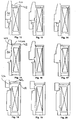
- FIG. 1 Within a housing formed of a yoke-side housing plate 10, a core-side housing plate 12 and a cylindrical housing shell 14, a stationary coil unit 16 is provided, which is connected in a manner not shown and in an otherwise known manner for energizing ,
- the apparatus further has a two-part core unit consisting of a stationary core portion 18 and a core unit 22 movable in the axial direction (dotted line 20). Passing through the core unit 18, 22 is an armature tappet portion 24 which is widened in diameter in the axial direction Anchor body portion 26 extends.
- Anchor tappet portion 24 and movable core portion 22 are also connected by means of respective abutment-forming annular shoulders 28 (FIG. Fig. 3 , for the tappet portion 24) and 30 (for the movable core portion) and form a driver unit (entrainment means), indicated by the dashed border 32 in Fig. 3 , out. especially the Fig. 3 also illustrates the core gap 34 formed in the axial direction between the units 22 and 18.
- the operation of the device according to Fig. 1 to 3 explains Fig. 2 the magnetic field line through the related Fig. 1 explained components after the energizing explained:
- the application of the electrical signal to the coil unit 16 generates a magnetic field course corresponding to the arrowheads 34 and 36 through the surrounding housing of magnetically conductive material, at the same time a magnetic flux takes place from the anchor body portion 26 in the plunger portion 24 and from there into the stationary core portion 18, in addition also directly over the anchor body portion 26 in the movable core portion 22 (via a narrow air gap formed therebetween) and then via the core gap 34 in the stationary core portion 28.
- This second field pattern causes a high force acts on the movable core portion 24 to close the gap 34.
- the 4 and 5 clarify variants for the stepped training of the Mit Conversestoff 32: So illustrates the Fig. 4 instead of the stages 30 (for the movable core section) and 28 (for the plunger section) an interacting pair of Koni 28a, 30a, which analogous to the annular shoulder shape of Fig. 3 are formed as a ring Koni and act in the manner shown as a driver that transmit the closing of the core gap causing force on the anchor.
- Fig. 12 to 20 illustrate further modifications of the invention:
- the second embodiment of the Fig. 12 to 14 the addition and / or replacement of the principle of Fig. 1 to 11 by a suitably coupled to the armature, movable yoke plate 40, which is driven to close a force-supporting gap 42 when energized and exerts a force assistance to the anchor with the above-described principle.
- the yoke plate 40 b in the embodiment of Fig. 18 to 20 held between an armature shoulder 46 for transmitting power to the armature and a housing-side shoulder 48 for limiting the stroke of the yoke plate 40b.
Landscapes
- Physics & Mathematics (AREA)
- Electromagnetism (AREA)
- Engineering & Computer Science (AREA)
- Power Engineering (AREA)
- Electromagnets (AREA)
- Valve Device For Special Equipments (AREA)
- Reciprocating, Oscillating Or Vibrating Motors (AREA)
- Magnetically Actuated Valves (AREA)
Description
- Die vorliegende Erfindung betrifft eine elektromagnetische Stellvorrichtung nach dem Oberbegriff des Hauptanspruchs.
- Eine derartige, etwa aus dem Deutschen Gebrauchsmuster
20 2006 011 905 der Anmelderin bekannte Vorrichtung ist aus dem Stand der Technik allgemein bekannt und offenbart einen (geeignet mit einem Stellpartner zusammenwirkenden) Ankerstößelabschnitt als axiale Fortsetzung eines Ankers, wobei der Anker mit einer stationären Kerneinheit sowie einer stationären Spuleneinheit so zusammenwirkt, dass als Reaktion auf das Bestromen der Spuleneinheit (Spulenvorrichtung) eine Ankerbewegung in einer axialen Richtung erfolgt. - Eine besondere Herausforderung, gerade im Zusammenhang mit einer Anwendung der gattungsgemäßen Technologie auf Ventile oder dergleichen Schaltaggregate, liegt darin, mit Beginn des Schaltvorgangs (d.h. mit Beginn der Bestromung) ein schnelles Ansprechen und eine hohe magnetische Stellkraft zu erreichen, sodass entsprechend geringe Totzeiten und eine hohe Dynamik der Vorrichtung erreichbar sind. Sogenannte Flachanker-Systeme ermöglichen üblicherweise große Kräfte, haben jedoch den Nachteil vergleichsweise kurzer nutzbarer Ankerhübe.
- Aus dem Stand der Technik ist es ferner bekannt, etwa mittels sogenannter Einzugsanker einen wirksamen Hub eines Ankers deutlich zu erhöhen, allerdings hat ein derartiger Ansatz den Nachteil, dass -- insbesondere unmittelbar nach dem Bestromen -- nur eine vergleichsweise geringe Magnetkraft erzeugt wird und dementsprechend nur ein langsames Ansprechen erreichbar ist.
- Aufgabe der vorliegenden Erfindung ist es daher, eine elektromagnetische Stellvorrichtung nach dem Oberbegriff des Hauptanspruchs sowohl im Hinblick auf ein Kraft- und Dynamikverhalten unmittelbar nach dem Bestromen zu verbessern, als auch einen wirksamen Hub zu vergrößern.
- Die Aufgabe wird durch die elektromagnetische Stellvorrichtung mit den Merkmalen des Hauptanspruchs gelöst; vorteilhafte Weiterbildungen der Erfindung sind in den Unteransprüchen beschrieben.
- So ist es zunächst erfindungsgemäß vorgesehen, die Kerneinheit in der axialen Richtung mehrteilig auszubilden, und zwar einem stationären Kernabschnitt einen axial beweglichen Kernabschnitt so zuzuordnen, dass zwischen diesen Abschnitten ein Kernspalt besteht, welcher Teil des magnetischen Kreises ist und zur zusätzlichen Krafterzeugung unmittelbar nach der Bestromung beitragen kann. Ferner sind der bewegliche Kernabschnitt und der Anker so mittels der erfindungsgemäßen Mitnehmermittel verbunden, dass als Reaktion auf die Bestromung und ein dadurch bewirktes Schließen des Kernspalts der bewegliche Kernabschnitt eine in der axialen Richtung wirkende Antriebskraft auf den Anker ausübt und so Dynamikverhalten und Kraftentwicklung unmittelbar nach der Bestromung (genauer: nach dem Beginn der Bestromung) optimiert; sobald dann der Kernspalt geschlossen ist, bewegt sich der Anker in ansonsten bekannter Weise in der Art eines Einzugsankers weiter in der axialen Richtung.
- Diese Vorgehensweise bewirkt damit vorteilhaft, dass in der für das Ansprechverhalten und die Dynamik kritische Phase unmittelbar nach der Bestromung (genauer: dem Aktivieren der Bestromung) eine hohe Kraft auf den Anker wirkt, welche diesen in der axialen Richtung antreibt, wobei diese Kraft einerseits in der gattungsgemäß bekannten Weise durch magnetischen Feldlinienfluss zwischen Anker und Kerneinheit bewirkt wird, insbesondere jedoch auch eine Unterstützung erfährt durch den zwischen dem beweglichen und dem stationären Kernabschnitt gebildeten Kernspalt, welcher beim durch das Bestromen bewirkten Schließen den vorteilhaften Krafteintrag auf den Anker ausübt.
- Weiterbildungsgemäß besonders bevorzugt ist es, die Mitnehmermittel am (im Durchmesser gegenüber einem breiteren Ankerkörperabschnitt verringerten) Ankerstößelabschnitt vorzusehen, weiter bevorzugt in einem Übergangs- bzw. Durchtrittsbereich des Ankerstößelabschnitts durch einen weiter bevorzugt becherförmigen beweglichen Kernabschnitt: Auf diese Weise lässt sich besonders geeignet, etwa durch das Vorsehen von treppen- und/oder rampenförmiger Mitnehmermitteln, die Kraftübertragung auf den Anker bewirken, darüber hinaus sind Herstellung und Montage drastisch vereinfacht: So ist es im Rahmen bevorzugter Weiterbildungen der Erfindung vorgesehen, den Ankerstößelabschnitt mit einem (ein- oder mehrstückigen) Ringabsatz zu versehen, welcher mit einem entsprechenden Mitnehmer-Partner, etwa am beweglichen Kernabschnitt, mitnehmend zusammenwirkt, sodass die zwischen beweglichem und stationärem Kernabschnitt erzeugte, ein Schließen des Kernspalts bewirkende Kraft wirksam auf den Anker übertragen wird. Ergänzend oder alternativ scheint etwa eine konische oder andere geometrische Ausgestaltung dieses Mitnehmerabschnitts möglich und sinnvoll.
- Darüber hinaus ist es von Weiterbildungen der Erfindung umfasst, die konstruktive Realisierung der elektromagnetischen Stellvorrichtung an nahezu beliebige Einsatzzwecke anzupassen und geeignet konstruktiv weiterzubilden, etwa in Form einer hub-begrenzenden Führung des Ankers mittels eines Ankerführungsrohres. Auch ist es von der Erfindung umfasst, den Gedanken der Erfindung eines geteilten und teilbeweglichen Kerns zur Kraftunterstützung zu übertragen bzw. zu ergänzen durch einen entsprechend konfigurierten Jochabschnitt, welcher gleichermaßen eine Ankerbewegung fördert bzw. eine Kraftbeaufschlagung des Ankers ermöglicht.
- Weitere Vorteile, Merkmale und Einzelheiten der Erfindung ergeben sich aus der nachfolgenden Beschreibung bevorzugter Ausführungsbeispiele sowie anhand der Zeichnungen; diese zeigen in
- Fig. 1:
- einen schematischen Längsschnitt durch eine elektromagnetische Stellvorrichtung gemäß einer ersten, bevorzugten Ausführungsform der vorliegenden Erfindung;
- Fig. 2:
- eine Darstellung analog
Fig. 1 zur Verdeutlichung des magnetischen Kraftflusses bei der Bestromung (nach dem Beginn der Bestromung); - Fig. 3:
- eine Detailansicht zur Verdeutlichung der mechanischen Kraftübertragung zwischen dem Anker und der zweigeteilten Kerneinheit mit diese verbindenden Mitnehmermitteln;
- Fig. 4, Fig. 5:
- zwei Prinzipdarstellungen für weitere Varianten zur Ausbildung der Geometrie der Mitnehmermittel
Fig. 6 : mittels Koni (Fig. 4 ) bzw. mehrstufiger Ringabsätze (Fig. 5 ); ein Kraft-/Wegdiagramm zur Verdeutlichung des durch die Erfindung realisierten starken Kraftanstiegs beim Ansprechen bzw. unmittelbar nach dem Bestromen; - Fig. 7 - Fig. 11:
- eine Abfolge von fünf zeitlich aufeinanderfolgenden Bewegungszuständen nach dem Bestromen der Vorrichtung gemäß
Fig. 1 bis Fig. 3 ; - Fig. 12 - Fig. 14:
- eine Darstellung analog
Fig. 7 bis 11 zur Verdeutlichung der Funktionsweise und konstruktiven Realisierung einer zweiten Ausführungsform der vorliegenden Erfindung; - Fig. 15 - Fig. 17:
- eine Darstellung analog
Fig. 7 bis 11 zur Verdeutlichung der konstruktiven Realisierung und Funktionsweise einer dritten Ausführungsform der vorliegenden Erfindung und - Fig. 18 - Fig. 20:
- eine Darstellung analog
Fig. 7 bis 11 zur Verdeutlichung der konstruktiven Realisierung und Funktionsweise einer vierten Ausführungsform der vorliegenden Erfindung. - Bei der Beschreibung der nachfolgenden Ausführungsbeispiele der Erfindung bezeichnen gleiche Bezugszeichen identische bzw. unmittelbar äquivalente Funktionskomponenten, sofern keine anderen Erläuterungen gegeben werden.
- So zeigt die schematische Längsschnittsansicht der
Fig. 1 den prinzipiellen Aufbau der elektromagnetischen Stellvorrichtung der gezeigten ersten Ausführungsform: Innerhalb eines aus einer jochseitigen Gehäuseplatte 10, einer kernseitigen Gehäuseplatte 12 und einem zylindrischen Gehäusemantel 14 gebildeten Gehäuses ist eine stationäre Spuleneinheit 16 vorgesehen, welche in nicht gezeigter und in ansonsten bekannter Weise zur Bestromung beschaltet ist. Die Vorrichtung besitzt ferner eine zweigeteilte Kerneinheit bestehend aus einem stationären Kernabschnitt 18 und einem in der axialen Richtung (Strichpunktlinie 20) beweglichen Kerneinheit 22. Durch die Kerneinheit 18, 22 geführt ist ein Ankerstößelabschnitt 24, welcher sich in der axialen Richtung von einem im Durchmesser verbreiterten Ankerkörperabschnitt 26 erstreckt. - Ankerstößelabschnitt 24 und beweglicher Kernabschnitt 22 sind zudem verbunden mittels jeweiliger, einen Anschlag bildender Ringabsätze 28 (
Fig. 3 , für den Stößelabschnitt 24) bzw. 30 (für den beweglichen Kernabschnitt) und bilden eine Mitnehmereinheit (Mitnehmermittel), angedeutet durch die gestrichelte Umrandung 32 inFig. 3 , aus. Insbesondere dieFig. 3 verdeutlicht auch den in der axialen Richtung zwischen den Einheiten 22 und 18 gebildeten Kernspalt 34. - Unter Bezug auf die
Fig. 7 bis 11 wird die Funktionsweise der Vorrichtung gemäßFig. 1 bis 3 erläutert, wobeiFig. 2 den magnetischen Feldlinienverlauf durch die im Zusammenhang mitFig. 1 erläuterten Komponenten nach dem Bestromen erläutert: Das Anlegen des elektrischen Signals an die Spuleneinheit 16 erzeugt einen magnetischen Feldverlauf entsprechend der Pfeilschaaren 34 und 36 durch das umgebende Gehäuse aus magnetisch leitendem Material, gleichzeitig findet ein magnetischer Fluss statt vom Ankerkörperabschnitt 26 in den Stößelabschnitt 24 und von dort in den stationären Kernabschnitt 18, zusätzlich auch unmittelbar über den Ankerkörperabschnitt 26 in den beweglichen Kernabschnitt 22 (über einen dazwischen gebildeten, schmalen Luftspalt) und dann über den Kernspalt 34 in den stationären Kernabschnitt 28. Gerade dieser zweite Feldverlauf führt dazu, dass eine hohe Kraft auf den beweglichen Kernabschnitt 24 wirkt, um den Spalt 34 zu schließen. Diese Kraft wird mithilfe des Kraftschlusses der Absätze 30, 28 (Mitnehmermittel 32) übertragen auf den Ankerstößelabschnitt 24 und damit den gesamten Anker, sodass in dieser Frühphase der Bestromung (kurz nach der Bestromung bzw. im Einschalten der Bestromung) bereits eine hohe Kraft (und entsprechend ein schnelles Ansprechen) erreicht ist. Dies ist im linksseitigen Bereich derFig. 6 verdeutlicht. Entsprechend führt diese Kraft zu einem Schließen des Spalts 34 (Fig. 8 , wobeiFig. 7 insoweit der Ausgangssituation derFig. 3 entspricht), und nach dem Schließen des Spalts bewegt sich der Anker weiter in der Art eines herkömmlichen Einzugsankers (mit einteiligem Kern), vergleicheFig. 9 , bis endseitige Anschlagpositionen (Fig. 10 bzw.Fig. 11 ) erreicht werden. - Bemerkenswert ist bei dieser Realisierungsform, dass -- untypisch für einen Einzugsanker -- bereits unmittelbar nach dem Aktivieren der Bestromung ein sehr hoher Krafteintrag auf den Anker mit entsprechender Auswirkung auf Ansprech- und Dynamikverhalten erreicht ist.
- Die
Fig. 4 und 5 verdeutlichen Varianten zur gestuften Ausbildung der Mitnehmermittel 32: So verdeutlicht dieFig. 4 anstelle der Stufen 30 (für den beweglichen Kernabschnitt) bzw. 28 (für den Stößelabschnitt) ein miteinander wirkendes Paar von Koni 28a, 30a, welche analog der Ringabsatzform derFig. 3 als Ringkoni ausgebildet sind und in der gezeigten Weise als Mitnehmer wirken, die das Schließen des Kernspalts bewirkende Kraft auf den Anker übertragen. - Entsprechend enthält die in
Fig. 5 skizzierte Realisierung der Mitnehmermittel ein aufeinander bezogenes, mehrfach abgestuftes Paar von Ringabsätzen 28b bzw. 30b. - Die
Fig. 12 bis 20 verdeutlichen weitere Modifikationen der Erfindung: So zeigt das zweite Ausführungsbeispiel derFig. 12 bis 14 die Ergänzung und/oder das Ersetzen des Prinzips derFig. 1 bis 11 durch eine geeignet mit dem Anker gekoppelte, bewegliche Jochplatte 40, welche zum Schließen eines kraftunterstützenden Spalts 42 bei Bestromung angesteuert wird und mit dem vorbeschriebenen Prinzip eine Kraftunterstützung auf den Anker ausübt. - Entsprechendes gilt für die modifizierte bewegbare Jochplatte 40a gemäß Ausführungsbeispiel der
Fig. 15 bis 17 : Hier ist gezeigt, wie die bewegbare Jochplatte 40a unmittelbar auf einen Ringabsatz 44 des Ankers 26 greift. - Dagegen ist die Jochplatte 40b im Ausführungsbeispiel der
Fig. 18 bis 20 gehalten zwischen einem Ankerabsatz 46 zur Kraftübertragung auf den Anker und einem gehäuseseitigem Absatz 48 zur Hubbegrenzung der Jochplatte 40b.
Claims (11)
- Elektromagnetische Stellvorrichtung mit
einem einen langgestreckten Ankerstößelabschnitt (24) sowie einen diesen axial fortsetzenden Ankerkörperabschnitt (26) aufweisenden Anker,
der zum magnetischen Zusammenwirken mit einer Kerneinheit (18,22) sowie durch Bestromung einer stationär vorgesehenen Spulenvorrichtung (16) relativ zu dieser bewegbar ausgebildet ist,
dadurch gekennzeichnet, dass
die Kerneinheit so ausgebildet ist, dass sie zumindest abschnittsweise den Ankerstößelabschnitt (24) sowie den gegenüber dem Ankerstößelabschnitt im Durchmesser verbreiterten Ankerkörperabschnitt (26) umgibt,
die Kerneinheit in der axialen Richtung mehrteilig mit einem stationären Kernabschnitt (18), einem axial beweglichen Kernabschnitt (22) und einem veränderlichen Kernspalt (34) zwischen dem stationären und dem beweglichen Kernabschnitt ausgebildet ist
und der bewegliche Kernabschnitt und der Anker so ausgebildet und über Mitnehmermittel (32) verbunden sind, dass als Reaktion auf die Bestromung eine ein Schließen des Kernspalt bewirkende Bewegung des beweglichen Kernabschnitts sowie ein Antreiben des Ankers in der axialen Richtung über die Mitnehmermittel erfolgt, und sobald dann der Kernspalt geschlossen ist, der Anker sich weiter in der axialen Richtung bewegt. - Vorrichtung nach Anspruch 1, dadurch gekennzeichnet, dass die Mitnehmermittel (32) am Ankerstößelabschnitt vorgesehen sind.
- Vorrichtung nach Anspruch 1 oder 2, dadurch gekennzeichnet, dass die Mitnehmermittel einen mantelseitig am Anker vorgesehenen Absatz (28), insbesondere Ringabsatz, aufweisen.
- Vorrichtung nach Anspruch 3, dadurch gekennzeichnet, dass der Ringabsatz (28b) mehrstufig ausgebildet ist.
- Vorrichtung nach einem der Ansprüche 1 bis 4, dadurch gekennzeichnet, dass die Mitnehmermittel einen mantelseitig am Anker vorgesehen Konusabschnitt (28a), insbesondere Ringkonus, aufweisen.
- Vorrichtung nach einem der Ansprüche 1 bis 5, dadurch gekennzeichnet, dass der bewegliche Kernabschnitt (22) becherförmig ausgebildet und mit einem zum Hindurchführen des Stößelabschnitts (24) ausgebildeten axialen Durchbruch versehen ist.
- Vorrichtung nach Anspruch 6, dadurch gekennzeichnet, dass der bewegliche Kernabschnitt im äußeren Mantelbereich eine Konusform, insbesondere Ringkonusform, aufweist.
- Vorrichtung nach einem der Ansprüche 1 bis 7, dadurch gekennzeichnet, dass die Mitnehmermittel (32) am beweglichen Kernabschnitt in einem zum Durchführen des Ankerstößelabschnitts vorgesehenen Durchbruchsbereich ausgebildet sind.
- Vorrichtung nach Anspruch 8, dadurch gekennzeichnet, dass die Mitnehmermittel am beweglichen Kernabschnitt ringabsatz (30)- oder ringkonusförmig ausgestaltet sind.
- Vorrichtung nach einem der Ansprüche 1 bis 9, dadurch gekennzeichnet, dass der Anker in einem einen Ankerhub begrenzenden Ankerführungsrohr geführt ist.
- Vorrichtung nach einem der Ansprüche 1 bis 9, gekennzeichnet durch ein magnetisch mit dem Anker zusammenwirkendes, einen beweglichen Jochabschnitt (40,40a, 40b) aufweisendes Joch, welches so ausgebildet ist, dass es als Reaktion auf die Bestromung das Antreiben des Ankers mechanisch unterstützt.
Applications Claiming Priority (2)
| Application Number | Priority Date | Filing Date | Title |
|---|---|---|---|
| DE202008017033U DE202008017033U1 (de) | 2008-12-30 | 2008-12-30 | Elektromagnetische Stellvorrichtung |
| PCT/EP2009/008045 WO2010075909A1 (de) | 2008-12-30 | 2009-11-12 | Elektromagnetische stellvorrichtung |
Publications (2)
| Publication Number | Publication Date |
|---|---|
| EP2257954A1 EP2257954A1 (de) | 2010-12-08 |
| EP2257954B1 true EP2257954B1 (de) | 2012-01-04 |
Family
ID=42046305
Family Applications (1)
| Application Number | Title | Priority Date | Filing Date |
|---|---|---|---|
| EP09767941A Not-in-force EP2257954B1 (de) | 2008-12-30 | 2009-11-12 | Elektromagnetische stellvorrichtung |
Country Status (6)
| Country | Link |
|---|---|
| US (1) | US8939431B2 (de) |
| EP (1) | EP2257954B1 (de) |
| CN (1) | CN102265356B (de) |
| AT (1) | ATE540414T1 (de) |
| DE (1) | DE202008017033U1 (de) |
| WO (1) | WO2010075909A1 (de) |
Families Citing this family (5)
| Publication number | Priority date | Publication date | Assignee | Title |
|---|---|---|---|---|
| DE102010048808A1 (de) | 2010-10-20 | 2012-04-26 | Eto Magnetic Gmbh | Elektromagnetische Stellvorrichtung |
| DE102011015576B4 (de) * | 2011-03-30 | 2014-03-06 | Kendrion (Donaueschingen/Engelswies) GmbH | Schnellschaltender Hubmagnet |
| DE102012204466A1 (de) | 2012-03-21 | 2013-09-26 | Zf Friedrichshafen Ag | Elektromagnetische Stellvorrichtung |
| DE102012111851B4 (de) * | 2012-12-05 | 2023-03-16 | Eto Magnetic Gmbh | Elektromagnetische Stellvorrichtung |
| DE102020116857A1 (de) | 2019-07-08 | 2021-01-14 | ECO Holding 1 GmbH | Aktuator für ein Hydraulikventil und Hydraulikventil |
Family Cites Families (22)
| Publication number | Priority date | Publication date | Assignee | Title |
|---|---|---|---|---|
| US2407963A (en) * | 1943-01-11 | 1946-09-17 | Mcquay Norris Mfg Co | Solenoid |
| US2834570A (en) * | 1953-03-27 | 1958-05-13 | Honeywell Regulator Co | Solenoid valve |
| FR1496822A (fr) | 1966-08-26 | 1967-10-06 | Saunier Duval | Electrovanne électromagnétique à double noyau mobile |
| US3737141A (en) * | 1972-04-13 | 1973-06-05 | Control Concepts | Normally closed solenoid operated valve |
| US4056255A (en) * | 1975-05-08 | 1977-11-01 | Lace Donald A | Valve actuator |
| US5422617A (en) | 1993-05-28 | 1995-06-06 | Imc Magnetics Corp. | Multiple coil, multiple armature solenoid |
| DE19543142A1 (de) | 1995-11-18 | 1997-05-22 | Schultz Wolfgang E | Elektromagnet mit beweglichem Kernteil |
| IT1289794B1 (it) * | 1996-12-23 | 1998-10-16 | Elasis Sistema Ricerca Fiat | Perfezionamenti ad una valvola di dosaggio a comando elettromagnetico per un iniettore di combustibile. |
| DE19816315A1 (de) * | 1998-04-11 | 1999-10-14 | Bosch Gmbh Robert | Brennstoffeinspritzventil |
| DE19855547A1 (de) * | 1998-12-02 | 2000-06-08 | Bosch Gmbh Robert | Elektromagnetisch betätigbares Ventil |
| DE19904901A1 (de) * | 1999-02-06 | 2000-08-10 | Zahnradfabrik Friedrichshafen | Proportional-Druckregelventil |
| US6047718A (en) * | 1999-04-01 | 2000-04-11 | Emersonelectric Co. | Solenoid valve having coaxial armatures in a single coil design |
| FR2834378B1 (fr) | 2001-12-28 | 2004-09-24 | Peugeot Citroen Automobiles Sa | Electrovanne a course de deplacement des noyaux non limitee par le dimensionnement des bobines |
| JP2003217925A (ja) * | 2002-01-21 | 2003-07-31 | Mikuni Corp | リニアアクチュエータ装置および駆動制御方法 |
| US6877717B2 (en) * | 2003-03-14 | 2005-04-12 | Kelsey-Hayes Company | Control valve for a vehicular brake system |
| US7049916B2 (en) | 2004-01-21 | 2006-05-23 | Keihin Corporation | Electromagnetic apparatus |
| JP4383933B2 (ja) * | 2004-03-15 | 2009-12-16 | 三菱電機株式会社 | 電動制御弁の出力軸接続構造の製造方法 |
| JP4576908B2 (ja) * | 2004-07-13 | 2010-11-10 | オムロンヘルスケア株式会社 | ソレノイドエアーバルブ |
| KR20070038028A (ko) * | 2004-07-29 | 2007-04-09 | 미우라고교 가부시키카이샤 | 차단밸브 |
| US7163188B1 (en) * | 2004-07-30 | 2007-01-16 | Emerson Electric Co. | Solenoid valve for fluid flow |
| DE202006011905U1 (de) | 2006-08-03 | 2007-12-06 | Eto Magnetic Kg | Elektromagnetische Stellvorrichtung |
| KR100909426B1 (ko) | 2006-10-17 | 2009-07-24 | 엘에스산전 주식회사 | 액츄에이터 |
-
2008
- 2008-12-30 DE DE202008017033U patent/DE202008017033U1/de not_active Expired - Lifetime
-
2009
- 2009-11-12 WO PCT/EP2009/008045 patent/WO2010075909A1/de not_active Ceased
- 2009-11-12 CN CN200980152308.5A patent/CN102265356B/zh not_active Expired - Fee Related
- 2009-11-12 AT AT09767941T patent/ATE540414T1/de active
- 2009-11-12 EP EP09767941A patent/EP2257954B1/de not_active Not-in-force
- 2009-11-12 US US13/142,642 patent/US8939431B2/en active Active
Also Published As
| Publication number | Publication date |
|---|---|
| US20110266475A1 (en) | 2011-11-03 |
| US8939431B2 (en) | 2015-01-27 |
| CN102265356A (zh) | 2011-11-30 |
| WO2010075909A1 (de) | 2010-07-08 |
| EP2257954A1 (de) | 2010-12-08 |
| DE202008017033U1 (de) | 2010-05-12 |
| ATE540414T1 (de) | 2012-01-15 |
| CN102265356B (zh) | 2017-05-03 |
Similar Documents
| Publication | Publication Date | Title |
|---|---|---|
| EP0935262B1 (de) | Elektromagnet | |
| DE102007055578B4 (de) | Betätigungsmagnet zum Bewegen einer Verschlussnadel einer Heißkanaldüse eines Spritzgusswerkzeugs | |
| DE102016225324A1 (de) | Solenoidantrieb für einen Starter für eine Brennkraftmaschine | |
| EP3191695B1 (de) | Elektromagnetische stellvorrichtung | |
| EP2775485B1 (de) | Elektromagnetische Stellvorrichtung, insbesondere zur Nockenwellenverstellung einer Brennkraftmaschine | |
| EP2257954A1 (de) | Elektromagnetische stellvorrichtung | |
| EP2929550B1 (de) | Elektromagnetische stellvorrichtung | |
| DE202012104122U1 (de) | Elektromagnetische Stellvorrichtung | |
| EP2677161A2 (de) | Starterrelais für eine Startvorrichtung | |
| DE102016207564B3 (de) | Verfahren zum Öffnen und Schließen eines Schaltventils | |
| EP2516905B1 (de) | Elektromagnetventil | |
| EP2252774B1 (de) | Elektromagnetische nockenwellen-verstellvorrichtung | |
| DE102011015576B4 (de) | Schnellschaltender Hubmagnet | |
| DE102012222127A1 (de) | Kraftstoffinjektor | |
| WO2014016023A2 (de) | Elektromagnetische stellvorrichtung | |
| EP2665955B1 (de) | Schieberventil | |
| DE102008047364B4 (de) | Hubmagnet mit Lagerung des Hubankerkolbens im Magnetgehäuse | |
| EP1887214B1 (de) | Injektor und zugehöriges Betriebsverfahren | |
| DE102016107766A1 (de) | Elektromagnetventil sowie Betriebsverfahren | |
| DE102019118860A1 (de) | Elektromagnetische Stellvorrichtung mit aktivem Rückholhub | |
| DE102013201756A1 (de) | Steuerventil mit zwei Magnetspulen | |
| DE102012104715A1 (de) | Magnetischer Ventilaktuator | |
| DE102010063981A1 (de) | Magnetodynamischer Aktor und Verfahren zur Betätigung eines Kraftstoffeinspritzventils | |
| DE102013210744A1 (de) | Kraftstoffinjektor | |
| EP2649281B1 (de) | Nockenwellenbaugruppe sowie verfahren zum herstellen einer nockenwellenbaugruppe |
Legal Events
| Date | Code | Title | Description |
|---|---|---|---|
| PUAI | Public reference made under article 153(3) epc to a published international application that has entered the european phase |
Free format text: ORIGINAL CODE: 0009012 |
|
| 17P | Request for examination filed |
Effective date: 20100916 |
|
| AK | Designated contracting states |
Kind code of ref document: A1 Designated state(s): AT BE BG CH CY CZ DE DK EE ES FI FR GB GR HR HU IE IS IT LI LT LU LV MC MK MT NL NO PL PT RO SE SI SK SM TR |
|
| AX | Request for extension of the european patent |
Extension state: AL BA RS |
|
| GRAP | Despatch of communication of intention to grant a patent |
Free format text: ORIGINAL CODE: EPIDOSNIGR1 |
|
| DAX | Request for extension of the european patent (deleted) | ||
| RIN1 | Information on inventor provided before grant (corrected) |
Inventor name: SCHIEPP, THOMAS Inventor name: BUERSSNER, JOERG |
|
| GRAS | Grant fee paid |
Free format text: ORIGINAL CODE: EPIDOSNIGR3 |
|
| GRAA | (expected) grant |
Free format text: ORIGINAL CODE: 0009210 |
|
| AK | Designated contracting states |
Kind code of ref document: B1 Designated state(s): AT BE BG CH CY CZ DE DK EE ES FI FR GB GR HR HU IE IS IT LI LT LU LV MC MK MT NL NO PL PT RO SE SI SK SM TR |
|
| REG | Reference to a national code |
Ref country code: GB Ref legal event code: FG4D Free format text: NOT ENGLISH |
|
| REG | Reference to a national code |
Ref country code: CH Ref legal event code: EP |
|
| REG | Reference to a national code |
Ref country code: AT Ref legal event code: REF Ref document number: 540414 Country of ref document: AT Kind code of ref document: T Effective date: 20120115 |
|
| REG | Reference to a national code |
Ref country code: IE Ref legal event code: FG4D |
|
| REG | Reference to a national code |
Ref country code: DE Ref legal event code: R096 Ref document number: 502009002411 Country of ref document: DE Effective date: 20120308 |
|
| REG | Reference to a national code |
Ref country code: NL Ref legal event code: VDEP Effective date: 20120104 |
|
| PG25 | Lapsed in a contracting state [announced via postgrant information from national office to epo] |
Ref country code: SI Free format text: LAPSE BECAUSE OF FAILURE TO SUBMIT A TRANSLATION OF THE DESCRIPTION OR TO PAY THE FEE WITHIN THE PRESCRIBED TIME-LIMIT Effective date: 20120104 |
|
| LTIE | Lt: invalidation of european patent or patent extension |
Effective date: 20120104 |
|
| PG25 | Lapsed in a contracting state [announced via postgrant information from national office to epo] |
Ref country code: NO Free format text: LAPSE BECAUSE OF FAILURE TO SUBMIT A TRANSLATION OF THE DESCRIPTION OR TO PAY THE FEE WITHIN THE PRESCRIBED TIME-LIMIT Effective date: 20120404 Ref country code: HR Free format text: LAPSE BECAUSE OF FAILURE TO SUBMIT A TRANSLATION OF THE DESCRIPTION OR TO PAY THE FEE WITHIN THE PRESCRIBED TIME-LIMIT Effective date: 20120104 Ref country code: LT Free format text: LAPSE BECAUSE OF FAILURE TO SUBMIT A TRANSLATION OF THE DESCRIPTION OR TO PAY THE FEE WITHIN THE PRESCRIBED TIME-LIMIT Effective date: 20120104 Ref country code: BG Free format text: LAPSE BECAUSE OF FAILURE TO SUBMIT A TRANSLATION OF THE DESCRIPTION OR TO PAY THE FEE WITHIN THE PRESCRIBED TIME-LIMIT Effective date: 20120404 Ref country code: IS Free format text: LAPSE BECAUSE OF FAILURE TO SUBMIT A TRANSLATION OF THE DESCRIPTION OR TO PAY THE FEE WITHIN THE PRESCRIBED TIME-LIMIT Effective date: 20120504 Ref country code: NL Free format text: LAPSE BECAUSE OF FAILURE TO SUBMIT A TRANSLATION OF THE DESCRIPTION OR TO PAY THE FEE WITHIN THE PRESCRIBED TIME-LIMIT Effective date: 20120104 |
|
| REG | Reference to a national code |
Ref country code: IE Ref legal event code: FD4D |
|
| PG25 | Lapsed in a contracting state [announced via postgrant information from national office to epo] |
Ref country code: FI Free format text: LAPSE BECAUSE OF FAILURE TO SUBMIT A TRANSLATION OF THE DESCRIPTION OR TO PAY THE FEE WITHIN THE PRESCRIBED TIME-LIMIT Effective date: 20120104 Ref country code: GR Free format text: LAPSE BECAUSE OF FAILURE TO SUBMIT A TRANSLATION OF THE DESCRIPTION OR TO PAY THE FEE WITHIN THE PRESCRIBED TIME-LIMIT Effective date: 20120405 Ref country code: PL Free format text: LAPSE BECAUSE OF FAILURE TO SUBMIT A TRANSLATION OF THE DESCRIPTION OR TO PAY THE FEE WITHIN THE PRESCRIBED TIME-LIMIT Effective date: 20120104 Ref country code: LV Free format text: LAPSE BECAUSE OF FAILURE TO SUBMIT A TRANSLATION OF THE DESCRIPTION OR TO PAY THE FEE WITHIN THE PRESCRIBED TIME-LIMIT Effective date: 20120104 Ref country code: PT Free format text: LAPSE BECAUSE OF FAILURE TO SUBMIT A TRANSLATION OF THE DESCRIPTION OR TO PAY THE FEE WITHIN THE PRESCRIBED TIME-LIMIT Effective date: 20120504 |
|
| PG25 | Lapsed in a contracting state [announced via postgrant information from national office to epo] |
Ref country code: CY Free format text: LAPSE BECAUSE OF FAILURE TO SUBMIT A TRANSLATION OF THE DESCRIPTION OR TO PAY THE FEE WITHIN THE PRESCRIBED TIME-LIMIT Effective date: 20120104 |
|
| PG25 | Lapsed in a contracting state [announced via postgrant information from national office to epo] |
Ref country code: CZ Free format text: LAPSE BECAUSE OF FAILURE TO SUBMIT A TRANSLATION OF THE DESCRIPTION OR TO PAY THE FEE WITHIN THE PRESCRIBED TIME-LIMIT Effective date: 20120104 Ref country code: EE Free format text: LAPSE BECAUSE OF FAILURE TO SUBMIT A TRANSLATION OF THE DESCRIPTION OR TO PAY THE FEE WITHIN THE PRESCRIBED TIME-LIMIT Effective date: 20120104 Ref country code: DK Free format text: LAPSE BECAUSE OF FAILURE TO SUBMIT A TRANSLATION OF THE DESCRIPTION OR TO PAY THE FEE WITHIN THE PRESCRIBED TIME-LIMIT Effective date: 20120104 Ref country code: RO Free format text: LAPSE BECAUSE OF FAILURE TO SUBMIT A TRANSLATION OF THE DESCRIPTION OR TO PAY THE FEE WITHIN THE PRESCRIBED TIME-LIMIT Effective date: 20120104 Ref country code: IE Free format text: LAPSE BECAUSE OF FAILURE TO SUBMIT A TRANSLATION OF THE DESCRIPTION OR TO PAY THE FEE WITHIN THE PRESCRIBED TIME-LIMIT Effective date: 20120104 Ref country code: SE Free format text: LAPSE BECAUSE OF FAILURE TO SUBMIT A TRANSLATION OF THE DESCRIPTION OR TO PAY THE FEE WITHIN THE PRESCRIBED TIME-LIMIT Effective date: 20120104 |
|
| PLBE | No opposition filed within time limit |
Free format text: ORIGINAL CODE: 0009261 |
|
| STAA | Information on the status of an ep patent application or granted ep patent |
Free format text: STATUS: NO OPPOSITION FILED WITHIN TIME LIMIT |
|
| PG25 | Lapsed in a contracting state [announced via postgrant information from national office to epo] |
Ref country code: SK Free format text: LAPSE BECAUSE OF FAILURE TO SUBMIT A TRANSLATION OF THE DESCRIPTION OR TO PAY THE FEE WITHIN THE PRESCRIBED TIME-LIMIT Effective date: 20120104 |
|
| 26N | No opposition filed |
Effective date: 20121005 |
|
| REG | Reference to a national code |
Ref country code: DE Ref legal event code: R097 Ref document number: 502009002411 Country of ref document: DE Effective date: 20121005 |
|
| PG25 | Lapsed in a contracting state [announced via postgrant information from national office to epo] |
Ref country code: ES Free format text: LAPSE BECAUSE OF FAILURE TO SUBMIT A TRANSLATION OF THE DESCRIPTION OR TO PAY THE FEE WITHIN THE PRESCRIBED TIME-LIMIT Effective date: 20120415 |
|
| BERE | Be: lapsed |
Owner name: ETO MAGNETIC G.M.B.H. Effective date: 20121130 |
|
| PG25 | Lapsed in a contracting state [announced via postgrant information from national office to epo] |
Ref country code: BE Free format text: LAPSE BECAUSE OF NON-PAYMENT OF DUE FEES Effective date: 20121130 |
|
| PG25 | Lapsed in a contracting state [announced via postgrant information from national office to epo] |
Ref country code: MT Free format text: LAPSE BECAUSE OF FAILURE TO SUBMIT A TRANSLATION OF THE DESCRIPTION OR TO PAY THE FEE WITHIN THE PRESCRIBED TIME-LIMIT Effective date: 20120104 |
|
| PG25 | Lapsed in a contracting state [announced via postgrant information from national office to epo] |
Ref country code: TR Free format text: LAPSE BECAUSE OF FAILURE TO SUBMIT A TRANSLATION OF THE DESCRIPTION OR TO PAY THE FEE WITHIN THE PRESCRIBED TIME-LIMIT Effective date: 20120104 Ref country code: MC Free format text: LAPSE BECAUSE OF NON-PAYMENT OF DUE FEES Effective date: 20121130 |
|
| PG25 | Lapsed in a contracting state [announced via postgrant information from national office to epo] |
Ref country code: SM Free format text: LAPSE BECAUSE OF FAILURE TO SUBMIT A TRANSLATION OF THE DESCRIPTION OR TO PAY THE FEE WITHIN THE PRESCRIBED TIME-LIMIT Effective date: 20120104 Ref country code: LU Free format text: LAPSE BECAUSE OF NON-PAYMENT OF DUE FEES Effective date: 20121112 |
|
| REG | Reference to a national code |
Ref country code: CH Ref legal event code: PL |
|
| GBPC | Gb: european patent ceased through non-payment of renewal fee |
Effective date: 20131112 |
|
| PG25 | Lapsed in a contracting state [announced via postgrant information from national office to epo] |
Ref country code: HU Free format text: LAPSE BECAUSE OF FAILURE TO SUBMIT A TRANSLATION OF THE DESCRIPTION OR TO PAY THE FEE WITHIN THE PRESCRIBED TIME-LIMIT Effective date: 20091112 Ref country code: CH Free format text: LAPSE BECAUSE OF NON-PAYMENT OF DUE FEES Effective date: 20131130 Ref country code: LI Free format text: LAPSE BECAUSE OF NON-PAYMENT OF DUE FEES Effective date: 20131130 |
|
| PG25 | Lapsed in a contracting state [announced via postgrant information from national office to epo] |
Ref country code: GB Free format text: LAPSE BECAUSE OF NON-PAYMENT OF DUE FEES Effective date: 20131112 |
|
| PG25 | Lapsed in a contracting state [announced via postgrant information from national office to epo] |
Ref country code: MK Free format text: LAPSE BECAUSE OF FAILURE TO SUBMIT A TRANSLATION OF THE DESCRIPTION OR TO PAY THE FEE WITHIN THE PRESCRIBED TIME-LIMIT Effective date: 20120104 |
|
| REG | Reference to a national code |
Ref country code: FR Ref legal event code: PLFP Year of fee payment: 7 |
|
| REG | Reference to a national code |
Ref country code: AT Ref legal event code: MM01 Ref document number: 540414 Country of ref document: AT Kind code of ref document: T Effective date: 20141112 |
|
| PG25 | Lapsed in a contracting state [announced via postgrant information from national office to epo] |
Ref country code: AT Free format text: LAPSE BECAUSE OF NON-PAYMENT OF DUE FEES Effective date: 20141112 |
|
| REG | Reference to a national code |
Ref country code: FR Ref legal event code: PLFP Year of fee payment: 8 |
|
| REG | Reference to a national code |
Ref country code: FR Ref legal event code: PLFP Year of fee payment: 9 |
|
| PGFP | Annual fee paid to national office [announced via postgrant information from national office to epo] |
Ref country code: IT Payment date: 20231130 Year of fee payment: 15 Ref country code: FR Payment date: 20231123 Year of fee payment: 15 Ref country code: DE Payment date: 20231120 Year of fee payment: 15 |
|
| REG | Reference to a national code |
Ref country code: DE Ref legal event code: R082 Ref document number: 502009002411 Country of ref document: DE Representative=s name: PATENT- UND RECHTSANWALTSKANZLEI DAUB, DE Ref country code: DE Ref legal event code: R082 Ref document number: 502009002411 Country of ref document: DE Representative=s name: DAUB PARTG MBB, DE |
|
| REG | Reference to a national code |
Ref country code: DE Ref legal event code: R119 Ref document number: 502009002411 Country of ref document: DE |
|
| PG25 | Lapsed in a contracting state [announced via postgrant information from national office to epo] |
Ref country code: DE Free format text: LAPSE BECAUSE OF NON-PAYMENT OF DUE FEES Effective date: 20250603 |
|
| PG25 | Lapsed in a contracting state [announced via postgrant information from national office to epo] |
Ref country code: IT Free format text: LAPSE BECAUSE OF NON-PAYMENT OF DUE FEES Effective date: 20241112 |
|
| PG25 | Lapsed in a contracting state [announced via postgrant information from national office to epo] |
Ref country code: FR Free format text: LAPSE BECAUSE OF NON-PAYMENT OF DUE FEES Effective date: 20241130 |