EP2257757B2 - A plate heat exchanger - Google Patents
A plate heat exchanger Download PDFInfo
- Publication number
- EP2257757B2 EP2257757B2 EP08741887.7A EP08741887A EP2257757B2 EP 2257757 B2 EP2257757 B2 EP 2257757B2 EP 08741887 A EP08741887 A EP 08741887A EP 2257757 B2 EP2257757 B2 EP 2257757B2
- Authority
- EP
- European Patent Office
- Prior art keywords
- heat exchanger
- plate
- porthole
- area
- ridges
- Prior art date
- Legal status (The legal status is an assumption and is not a legal conclusion. Google has not performed a legal analysis and makes no representation as to the accuracy of the status listed.)
- Active
Links
- 239000002184 metal Substances 0.000 claims description 10
- CURLTUGMZLYLDI-UHFFFAOYSA-N Carbon dioxide Chemical group O=C=O CURLTUGMZLYLDI-UHFFFAOYSA-N 0.000 claims description 8
- 239000000463 material Substances 0.000 claims description 8
- 229910002092 carbon dioxide Inorganic materials 0.000 claims description 4
- 239000001569 carbon dioxide Substances 0.000 claims description 4
- 230000002093 peripheral effect Effects 0.000 description 6
- 238000005219 brazing Methods 0.000 description 4
- 239000002826 coolant Substances 0.000 description 2
- 238000006073 displacement reaction Methods 0.000 description 2
- 238000005728 strengthening Methods 0.000 description 2
- 238000001816 cooling Methods 0.000 description 1
- 230000007613 environmental effect Effects 0.000 description 1
- 239000013589 supplement Substances 0.000 description 1
Images


Classifications
-
- F—MECHANICAL ENGINEERING; LIGHTING; HEATING; WEAPONS; BLASTING
- F28—HEAT EXCHANGE IN GENERAL
- F28D—HEAT-EXCHANGE APPARATUS, NOT PROVIDED FOR IN ANOTHER SUBCLASS, IN WHICH THE HEAT-EXCHANGE MEDIA DO NOT COME INTO DIRECT CONTACT
- F28D9/00—Heat-exchange apparatus having stationary plate-like or laminated conduit assemblies for both heat-exchange media, the media being in contact with different sides of a conduit wall
- F28D9/0031—Heat-exchange apparatus having stationary plate-like or laminated conduit assemblies for both heat-exchange media, the media being in contact with different sides of a conduit wall the conduits for one heat-exchange medium being formed by paired plates touching each other
- F28D9/0043—Heat-exchange apparatus having stationary plate-like or laminated conduit assemblies for both heat-exchange media, the media being in contact with different sides of a conduit wall the conduits for one heat-exchange medium being formed by paired plates touching each other the plates having openings therein for circulation of at least one heat-exchange medium from one conduit to another
- F28D9/005—Heat-exchange apparatus having stationary plate-like or laminated conduit assemblies for both heat-exchange media, the media being in contact with different sides of a conduit wall the conduits for one heat-exchange medium being formed by paired plates touching each other the plates having openings therein for circulation of at least one heat-exchange medium from one conduit to another the plates having openings therein for both heat-exchange media
-
- F—MECHANICAL ENGINEERING; LIGHTING; HEATING; WEAPONS; BLASTING
- F28—HEAT EXCHANGE IN GENERAL
- F28F—DETAILS OF HEAT-EXCHANGE AND HEAT-TRANSFER APPARATUS, OF GENERAL APPLICATION
- F28F3/00—Plate-like or laminated elements; Assemblies of plate-like or laminated elements
- F28F3/02—Elements or assemblies thereof with means for increasing heat-transfer area, e.g. with fins, with recesses, with corrugations
- F28F3/04—Elements or assemblies thereof with means for increasing heat-transfer area, e.g. with fins, with recesses, with corrugations the means being integral with the element
- F28F3/042—Elements or assemblies thereof with means for increasing heat-transfer area, e.g. with fins, with recesses, with corrugations the means being integral with the element in the form of local deformations of the element
- F28F3/046—Elements or assemblies thereof with means for increasing heat-transfer area, e.g. with fins, with recesses, with corrugations the means being integral with the element in the form of local deformations of the element the deformations being linear, e.g. corrugations
-
- F—MECHANICAL ENGINEERING; LIGHTING; HEATING; WEAPONS; BLASTING
- F28—HEAT EXCHANGE IN GENERAL
- F28D—HEAT-EXCHANGE APPARATUS, NOT PROVIDED FOR IN ANOTHER SUBCLASS, IN WHICH THE HEAT-EXCHANGE MEDIA DO NOT COME INTO DIRECT CONTACT
- F28D21/00—Heat-exchange apparatus not covered by any of the groups F28D1/00 - F28D20/00
- F28D2021/0019—Other heat exchangers for particular applications; Heat exchange systems not otherwise provided for
- F28D2021/008—Other heat exchangers for particular applications; Heat exchange systems not otherwise provided for for vehicles
- F28D2021/0084—Condensers
-
- F—MECHANICAL ENGINEERING; LIGHTING; HEATING; WEAPONS; BLASTING
- F28—HEAT EXCHANGE IN GENERAL
- F28D—HEAT-EXCHANGE APPARATUS, NOT PROVIDED FOR IN ANOTHER SUBCLASS, IN WHICH THE HEAT-EXCHANGE MEDIA DO NOT COME INTO DIRECT CONTACT
- F28D21/00—Heat-exchange apparatus not covered by any of the groups F28D1/00 - F28D20/00
- F28D2021/0019—Other heat exchangers for particular applications; Heat exchange systems not otherwise provided for
- F28D2021/008—Other heat exchangers for particular applications; Heat exchange systems not otherwise provided for for vehicles
- F28D2021/0085—Evaporators
-
- F—MECHANICAL ENGINEERING; LIGHTING; HEATING; WEAPONS; BLASTING
- F28—HEAT EXCHANGE IN GENERAL
- F28F—DETAILS OF HEAT-EXCHANGE AND HEAT-TRANSFER APPARATUS, OF GENERAL APPLICATION
- F28F2225/00—Reinforcing means
- F28F2225/04—Reinforcing means for conduits
-
- F—MECHANICAL ENGINEERING; LIGHTING; HEATING; WEAPONS; BLASTING
- F28—HEAT EXCHANGE IN GENERAL
- F28F—DETAILS OF HEAT-EXCHANGE AND HEAT-TRANSFER APPARATUS, OF GENERAL APPLICATION
- F28F2275/00—Fastening; Joining
- F28F2275/04—Fastening; Joining by brazing
Definitions
- the present invention refers to a plate heat exchanger according to the preamble of claim 1, see FR-2850740 .
- a weak area in such plate heat exchangers is the porthole area, i.e. the area immediately around the portholes. These areas determine the design pressure in plate heat exchangers used today. However, although a certain design of the porthole area would improve the design pressure, this design would not improve the strength at another area of the plate heat exchanger, i.e. the problem would then merely be displaced.
- the object of the present invention is to provide a plate heat exchanger having a high design pressure, and more precisely a plate heat exchanger permitting a very high pressure of at least one of the media flowing therethrough.
- the small depth of the heat exchanger plates improves the strength of the plate and the plate heat exchanger.
- the small depth of the heat exchanger plates permits a small distance between corrugation elements, such as ridges and valleys, on the heat transfer area.
- Such a small distance between the corrugation elements means that the distance between the contact areas or joining areas between adjacent heat exchanger plates in the plate package also will be relatively short. Consequently, a small depth results in a small distance between the joining areas, and thus in a large number of such joining areas over the heat transfer area.
- the depth is equal to or less than 0,9 mm, more preferably equal to or less than 0,85 mm, and most preferably equal to or less than 0,80 mm.
- the metal sheet thickness t is approximately 0,3 mm.
- the braze material has a braze volume with respect to the heat exchanger area of the plate heat exchanger, wherein the first interspaces and the second interspaces have an interspace volume with respect to the heat transfer area of the plate heat exchanger and wherein the proportion of the braze volume to the interspace volume is at least 0,05.
- Such a relatively large volume of braze material enhances the strength of the joining between the heat exchanger plates, and thus the strength of the plate heat exchanger.
- each heat exchanger plate defines a longitudinal centre line, wherein the heat transfer area comprises ridges and valleys arranged in such a manner that the ridges of one of the heat exchanger plates abut the valleys of an adjoining one of the heat exchanger plates to form a plurality of joining areas.
- the ridges and valleys extend along at least an extension line forming an angle ⁇ of inclination with the centre line, wherein the angle ⁇ of inclination lies in the range 20° ⁇ ⁇ ⁇ 70°.
- the angle ⁇ of inclination is approximately 45°.
- Such an angle ⁇ of inclination provides a maximum of joining areas, and thus contributes to a high strength of the plate package and the plate heat exchanger.
- the extension line of each ridge and valley forms a positive angle ⁇ of inclination at one side of the centre line and a corresponding negative angle of inclination at the other side of the centre line, wherein the ridges and valleys form joining areas at the centre line.
- Such joining areas at the centre line provide a high strength in this area.
- the ridges are disposed at a distance from and extend in parallel with each other.
- the distance between adjacent ridges on the heat transfer area is less than 4 mm.
- Such a small distance between adjacent ridges is advantageous as explained above and contributes to a large number of joining areas at the heat transfer area.
- this distance may be approximately 3 mm.
- each porthole area comprises a first porthole area, a second porthole area, a third porthole area and a fourth porthole area.
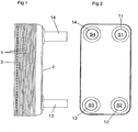
- Figs. 1 and 2 shows a plate heat exchanger comprising a plurality of heat exchanger plates 1, a first end plate 2, which is provided beside an outermost one of the heat exchanger plates 1, and a second end plate 3, which is provided beside the other opposite outermost heat exchanger plate 1.
- the heat exchanger plates 1 are produced through forming of a metal sheet and provided beside each other.
- the first end plate 2, the second end plate 3 and the heat exchanger plates 1 are permanently joined to each other through brazing by means of a braze material to form a plate package.
- the plate package define or have first plate interspaces 4 for a first medium and second plate interspaces 5 for a second medium, see Fig. 6 .
- the first and second medium may be any suitable heat transfer medium.
- the first and/or the second medium may be carbon dioxide.
- the plate heat exchanger of the embodiments disclosed has four portholes S1, S2, S3 and S4, wherein the porthole S1 is connected to a connection pipe 11 and communicates with the first plate interspaces 4, the porthole S2 is connected to a connection pipe 12 and communicates with the first plate interspaces 4, the porthole S3 is connected to a connection pipe 13 and communicates with the second plate interspaces 5 and the porthole S4 is connected to a connection pipe 14 and communicates with the second plate interspaces 5. It is to be noted that the plate heat exchanger may have another number of portholes than those disclosed, e.g. 2, 3, 5, 6, 7 or 8 portholes. Connection pipes may be provided extending from the first end plate 2, as disclosed, and/or from the second end plate 3.
- Each heat exchanger plate 1 has, in the embodiments disclosed, a rectangular shape with two long side edges 15 and two short side edges 16, see Fig. 3 .
- a longitudinal centre axis x extends between and in parallel with the two long side edges 15 and transversely to the short side edges 16.
- Each heat exchanger plate 1 also extends along a main extension plane p, see Fig. 6 .
- each heat exchanger plate 1 has a heat transfer area 20, at which the main part of the heat transfer between the first and second media take place, and a plurality of porthole areas 21-24.
- the porthole areas 21-24 comprise a first porthole area 21, a second porthole area 22, a third porthole area 23 and a fourth porthole area 24.
- Each porthole area 21-24 surrounds a respective porthole through the heat exchanger plate 1.
- Each porthole is defined by a porthole edge 25.
- All of the areas 20-24 extend, on one side of the heat exchanger plate 1, between a primary level p' at a distance from the main extension plane p, and a secondary level p" at a distance from and on an opposite side of the main extension plane p, see Fig. 6 .
- the primary level p' forms an upper level of the heat exchanger plate 1
- the secondary level p" forms a lower level of the heat exchanger plate 1 as seen in Fig. 6 .
- the primary level p' is thus located more closely to the first end plate 2 than the secondary level p".
- Each heat exchanger plate 1 also has a flange 26 extending around the heat exchanger plate 1 along the long side edges 15 and the short side edges 16. As can be seen in Fig. 6 , the flange 26 extends further away from the main extension plane p than the secondary level p".
- Each heat exchanger plate 1 is made through forming of a metal sheet having a metal sheet thickness t.
- the metal sheet thickness t may vary and be somewhat changed after the forming of the heat exchanger plate 1.
- the metal sheet thickness t, before the forming may lie in the range 0,2 ⁇ t ⁇ _0,4 mm.
- the metal sheet thickness t, before the forming may be 0,3 mm or approximately 0,3 mm.
- Each heat exchanger plate 1 also has a depth d, see Fig. 6 .
- the depth d is defined by the distance between the primary level p' and the secondary level p".
- the depth d may be equal to or less than 1,0 mm, preferably equal to or less than 0,90 mm, more preferably equal to or less than 0,85 mm or most preferably equal to or less than 0,80 mm.
- the heat transfer area 20 comprises a corrugation of ridges 27 and valleys 27' arranged in such a manner that the ridges 27 of one of the heat exchanger plates 1 abut the valleys 27' of an adjoining one of the heat exchanger plates 1 to form a plurality of joining areas 28 between a heat exchanger plate 1, indicated with full lines in Fig. 7 , and an adjacent heat exchanger plate 1, indicated with dotted lines in Fig. 7 .
- the ridges 27 are disposed at a distance r form each other, and extend in parallel with each other and with the valleys 27'.
- the ridges 27 and valleys 27' extend along an extension line e forming an angle ⁇ of inclination with the centre line x, see Fig. 7 .
- the angle ⁇ of inclination lies in the range 20° ⁇ ⁇ ⁇ 70°.
- the angle ⁇ of inclination may be 45°, or approximately 45°.
- the extension line e of each ridge 27 and valley 27' forms a positive angle ⁇ of inclination at one side of the centre line x and a corresponding negative angle ⁇ of inclination at the other side of the centre line x.
- the ridges 27 and valleys 27' also form joining areas 29 at the centre line x.
- joining areas 30 are formed between the flanges 26 of adjacent heat exchanger plates 1.
- the distance r between adjacent ridges 27, or between a respective central extension line e of adjacent ridges 27, may be less than 4 mm, or may be approximately 3 mm, or 3 mm, see Fig. 7 .
- the plate heat exchanger is brazed by means of a braze material introduced between the heat exchanger plates 1 before the brazing operation.
- the braze material has a braze volume with respect to the heat transfer area 20 of the plate heat exchanger.
- the first interspaces 4 and the second interspaces 5 of the plate heat exchanger have an interspace volume with respect to the heat transfer area 20 of the plate heat exchanger.
- Each porthole area 21-24 comprises an annular flat area 31, a set of inner portions 32 disposed on the annular flat area 31 and distributed along the porthole edge 25.
- the inner portions 32 are displaced from the annular flat area 31 in a normal direction with respect to the main extension plane p.
- Each porthole area 21-24 also comprises a set of outer portions 33 disposed on and distributed along the annular flat area 31 at a distance from the inner portions 32.
- the inner portions 32, which adjoin the porthole edge 25, extend to or are located at the same level as the outer portions 33, whereas the annular flat area 31 is located at another level than the inner portions 32 and the outer portions 33.
- the inner portions 32 and the outer portions 33 of the first porthole area 21 and the second porthole area 22 extend to or are located at the secondary level p", whereas the annular flat area 31 of the first porthole area 21 and the second porthole area 22 is located at the primary level p'. Furthermore, the inner portions 32 and the outer portions 33 of the third porthole area 23 and the fourth porthole area 24 extend to or are located at the primary level p', whereas the annular flat area 31 of the third porthole area 23 and the fourth porthole area 24 is located at the secondary level p".
- Each inner portion 32 have a flat extension at the respective level p' and p", and each outer portion 33 have a flat extension at the respective level p' and p".
- every second heat exchanger plate 1 is rotated 180° in the main extension plane p.
- the inner portions 32 of one heat exchanger plate 1 will adjoin and be joined to a respective one of the inner portions 32 of an adjacent heat exchanger plate 1.
- the outer portions 33 of one heat exchanger plate 1 will adjoin and be joined to a respective one of the outer portions 33 of an adjacent heat exchanger plate 1. More specifically, the inner portions 32 and the outer portions 33 of the first porthole area 21 of one heat exchanger plate 1 will be joined to a respective one of the inner portions 32 and the outer portions 33 of the third porthole area 23 of an adjacent heat exchanger plate 1 in the plate package.
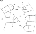
- each inner portion 32 has an inner part 41 extending to and adjoining the porthole edge 25. Moreover, each inner portion 32 has an outer segment 42 adjoining the inner part 41 and having an angular extension of at least 180°. The outer segment 42 adjoins the annular flat portion 31. The outer segment 42 has a continuous contour and a radius R.
- the radius R is substantially constant and allowed to vary within the range of 0,8 R ⁇ R ⁇ 1,2 R, more specifically within the range 0,9 R ⁇ R ⁇ 1,1 R, and most specifically within the range of 0,95 R ⁇ R ⁇ 1,05 R.
- each of the outer portions 33 may have an inner segment 45 adjoining the annular flat area 31 and having an angular extension of at least 90°, at least 120°, or at least 150°.
- the inner segment 45 preferably also has a continuous contour, and may have a radius R', which is constant or substantially constant, and allowed to vary within a range 0,8 R' ⁇ R' ⁇ 1,2 R', more specifically within the range 0,9 R ⁇ R ⁇ 1,1 R, and most specifically within the range of 0,95 R ⁇ R ⁇ 1,05 R.
- both the inner portions 32 and the outer portions 33 of each porthole area 21-24 are uniformly distributed around the respective porthole. More specifically, the inner portions 32 present an equal inner angular distance between adjacent inner portions 32. The outer portions 33 present an equal outer angular distance between adjacent outer portions 33. Furthermore, the outer portions 33 of the first porthole area 21 and the third porthole area 23 have a first relative peripheral position with respect to the inner portions 32 of these two porthole areas 21 and 23. The outer portions 33 of the second porthole area 22 and the fourth porthole area 24 have a second relative peripheral position with respect of the inner portions 32 of these two porthole areas 22 and 24. It can be seen from Fig. 4 that the first relative peripheral position is displaced peripherally, or includes a peripheral displacement, in relation to the second relative peripheral position. The peripheral displacement is, in the embodiments disclosed, equal to half, or approximately half, the equal outer angular distance between the adjacent outer portions 33.
- each porthole area 21-24 comprises 9 inner portions 32 and 18 outer portions 33. This is a suitable number of inner portions 32 and outer portions 33. In the embodiments disclosed, the inner angular distance is about twice the outer angular distance. It is to be noted however, that the number of inner portions 32 and the number of outer portions 33 can vary and deviate from the numbers disclosed.
- Each of the four connection pipes 11-14 is joined to a respective one of the porthole areas 21-24 and comprises a flat element 50.
- Each flat element 50 forms an attachment flange attached to or integral with a respective connection pipe 11-14 and joined to the plate package, see Figs. 8 and 9 .
- All of the flat elements 50 are provided between one of the end plates 2, 3 and one of the outermost heat exchanger plates 1. More specifically, in the embodiments disclosed, each flat element 50 is provided between one of the outermost heat exchanger plates 1 and the first end plate 2.
- the flat elements 50 are brazed to the outermost heat exchanger plate 1 and the first end plate 2.
- the area around each porthole of the first end plate 2 is raised at a raised portion 2a to provide a space for the respective flat element 50 as can be seen in Figs.
- the flat element 50 has a flat, or a substantially flat, bottom surface 51 abutting and joined to the annular flat area 31 of the outermost heat exchanger plate 1 at the first porthole area 21 and the second porthole area 22, respectively.
- the annular flat area 31 is thus located at the primary level p', see Fig. 8 .
- each flat element 50 comprises an annular protrusion 52 projecting from the flat bottom surface 51 and turned towards the plate package.
- the annular protrusion 52 tightly abuts the annular flat area 31 of the outermost heat exchanger plate 1 at the third porthole area 23 and the fourth porthole area 24, respectively.
- the annular flat area 31 is thus located at the secondary level p", see Fig. 9 . Consequently, a secure and tight abutment of the flat elements 50 is ensured for all of the portholes S1-S4.
- the flat elements 53 do not form a part of a connection pipe 11-14 and cover the respective porthole.
- the flat element 53 for the portholes S1 and S2 has a flat, or substantially flat, bottom surface 51 tightly abutting and joined to the annular flat area 31 of the other outermost heat exchanger plate 1 in the same way as the flat element 50.
- the flat element 53 for the portholes S3 and S4 has a flat bottom surface 51 with an annular protrusion 52 tightly abutting and joined to the annular flat area of the other outermost heat exchanger plate 1.
- the second end plate 3 has a raised portion 3a around each porthole.
- one or more of the flat elements 53 may be replaced by a respective connection pipe having a flat element 50 in case an inlet and/or an outlet is to be provided as an alternative or supplement through the second end plate 3.
- Figs. 10 and 11 disclose a further embodiment which differs from the embodiment disclosed in Figs. 8 and 9 merely in that the connection pipe 11-15 comprises an external thread 55 and that the flat element 50 is brazed to the connection pipe 11-15.
- the flat element 50 can be disposed between the outermost heat exchanger plate 1 and the first end plate 2.
- the connection pipe 11-15 may thereafter be introduced into the respective porthole to be brazed to the flat element 50 in connection with the brazing of the plate heat exchanger.
Applications Claiming Priority (1)
| Application Number | Priority Date | Filing Date | Title |
|---|---|---|---|
| PCT/SE2008/050397 WO2009123517A1 (en) | 2008-04-04 | 2008-04-04 | A plate heat exchanger |
Publications (4)
| Publication Number | Publication Date |
|---|---|
| EP2257757A1 EP2257757A1 (en) | 2010-12-08 |
| EP2257757A4 EP2257757A4 (en) | 2013-05-22 |
| EP2257757B1 EP2257757B1 (en) | 2015-07-01 |
| EP2257757B2 true EP2257757B2 (en) | 2021-09-29 |
Family
ID=41135789
Family Applications (1)
| Application Number | Title | Priority Date | Filing Date |
|---|---|---|---|
| EP08741887.7A Active EP2257757B2 (en) | 2008-04-04 | 2008-04-04 | A plate heat exchanger |
Country Status (10)
| Country | Link |
|---|---|
| US (1) | US9103597B2 (zh) |
| EP (1) | EP2257757B2 (zh) |
| JP (1) | JP2011517763A (zh) |
| KR (1) | KR101234500B1 (zh) |
| CN (1) | CN102016480B (zh) |
| AU (1) | AU2008354066B2 (zh) |
| BR (1) | BRPI0822498B8 (zh) |
| CA (1) | CA2719328C (zh) |
| ES (1) | ES2544483T5 (zh) |
| WO (1) | WO2009123517A1 (zh) |
Families Citing this family (18)
| Publication number | Priority date | Publication date | Assignee | Title |
|---|---|---|---|---|
| PT2394129E (pt) * | 2009-02-04 | 2014-12-09 | Alfa Laval Corp Ab | Permutador de calor de placas |
| JP2011106764A (ja) * | 2009-11-19 | 2011-06-02 | Mitsubishi Electric Corp | プレート式熱交換器及びヒートポンプ装置 |
| SE534918C2 (sv) | 2010-06-24 | 2012-02-14 | Alfa Laval Corp Ab | Värmeväxlarplatta och plattvärmeväxlare |
| US10401094B2 (en) | 2011-02-08 | 2019-09-03 | Carrier Corporation | Brazed plate heat exchanger for water-cooled heat rejection in a refrigeration cycle |
| US9884169B2 (en) | 2011-08-17 | 2018-02-06 | Access Scientific, Llc | Access device with valve |
| JP5538344B2 (ja) * | 2011-11-09 | 2014-07-02 | 三菱電機株式会社 | プレート式熱交換器及びヒートポンプ装置 |
| JP5719820B2 (ja) * | 2012-10-23 | 2015-05-20 | 株式会社日阪製作所 | プレート式熱交換器 |
| EP3062949B2 (en) * | 2013-10-29 | 2023-05-24 | SWEP International AB | A method of brazing a plate heat exchanger using scren printed brazing material |
| EP3093602B1 (en) | 2015-05-11 | 2020-04-15 | Alfa Laval Corporate AB | A heat exchanger plate and a plate heat exchanger |
| US10697677B2 (en) * | 2015-12-11 | 2020-06-30 | Mitsubishi Electric Corporation | Plate type heat exchanger and refrigeration cycle apparatus |
| EP3447429B1 (en) * | 2017-08-22 | 2023-06-07 | InnoHeat Sweden AB | Heat exchanger plate and heat exchanger |
| ES2787017T3 (es) * | 2017-08-22 | 2020-10-14 | Innoheat Sweden Ab | Intercambiador de calor |
| SE541917C2 (en) * | 2018-01-16 | 2020-01-07 | Swep Int Ab | Method for producing a brazed plate heat exchanger |
| DK3587984T3 (da) * | 2018-06-28 | 2021-02-08 | Alfa Laval Corp Ab | Varmeoverføringsplade og tætning |
| EP3598046B1 (en) * | 2018-07-20 | 2023-05-17 | Valeo Vyminiky Tepla, s.r.o. | Heat exchanger plate and heat exchanger comprising such a heat exchanger plate |
| SE543338C2 (en) * | 2019-04-04 | 2020-12-08 | Swep Int Ab | Stencil device and method for stencil printing of brazing material onto a heat exchanger plate and use thereof |
| CN111928705B (zh) * | 2019-05-13 | 2022-03-25 | 亚浩电子五金塑胶(惠州)有限公司 | 具有重力型回路热管的散热装置 |
| SE545536C2 (en) * | 2020-02-14 | 2023-10-17 | Alfa Laval Corp Ab | A heat exchanger plate, and a plate heat exchanger |
Family Cites Families (31)
| Publication number | Priority date | Publication date | Assignee | Title |
|---|---|---|---|---|
| DE1930347C3 (de) * | 1969-06-14 | 1975-03-20 | Linde Ag, 6200 Wiesbaden | Plattenwärmetauscher |
| GB1500715A (en) * | 1974-05-24 | 1978-02-08 | Apv Co Ltd | Plate heat exchangers |
| SE7508256L (sv) * | 1975-07-18 | 1977-01-19 | Munters Ab Carl | Sett att framstella en vermevexlarkorpp for rekuperativa vexlare |
| US4411310A (en) * | 1978-04-07 | 1983-10-25 | The Boeing Company | Heat exchange apparatus having thin film flexible sheets |
| SU974090A1 (ru) | 1979-03-05 | 1982-11-15 | Предприятие П/Я Р-6273 | Пластинчатый теплообменный элемент |
| SE446562B (sv) * | 1982-03-04 | 1986-09-22 | Malte Skoog | Plattvermevexlare med turbulensalstrande asar innefattande ett forsta slag av plattor der asarna bildar viss vinkel med plattans langsida och ett andra slag med en viss annan vinkel |
| SU1343233A1 (ru) | 1985-07-10 | 1987-10-07 | Одесский Технологический Институт Холодильной Промышленности | Насадка контактного теплообменного аппарата |
| SE458884B (sv) * | 1987-05-29 | 1989-05-16 | Alfa Laval Thermal Ab | Permanent sammanfogad plattvaermevaexlare med sammanhaallande organ vid portarna |
| CN87211550U (zh) * | 1987-08-08 | 1988-05-18 | 国营绿洲机器厂 | 横人字形波纹板 |
| US5287918A (en) * | 1990-06-06 | 1994-02-22 | Rolls-Royce Plc | Heat exchangers |
| SE504868C2 (sv) * | 1995-10-23 | 1997-05-20 | Swep International Ab | Plattvärmeväxlare med ändplatta med pressat mönster |
| IT1276990B1 (it) * | 1995-10-24 | 1997-11-03 | Tetra Laval Holdings & Finance | Scambiatore di calore a piastre |
| JPH1096595A (ja) * | 1996-09-20 | 1998-04-14 | Honda Motor Co Ltd | 丸多板型オイルクーラ |
| SE513784C2 (sv) | 1999-03-09 | 2000-11-06 | Alfa Laval Ab | Permanent sammanfogad plattvärmeväxlare |
| JP2001133193A (ja) * | 1999-11-10 | 2001-05-18 | Ebara Corp | プレート式熱交換器 |
| EP1272804A2 (de) * | 2000-03-16 | 2003-01-08 | Robert Bosch Gmbh | Wärmeübertrager für eine co2-fahrzeugklimaanlage |
| JP2002107074A (ja) | 2000-09-29 | 2002-04-10 | Sanyo Electric Co Ltd | プレート型熱交換器及びそれを用いたヒートポンプ給湯機 |
| US6596229B2 (en) * | 2000-12-29 | 2003-07-22 | United Technologies Corporation | Silver braze alloy |
| JP3642739B2 (ja) * | 2001-02-20 | 2005-04-27 | 京セラ株式会社 | 半導体素子収納用パッケージ |
| SE520673C2 (sv) * | 2001-12-17 | 2003-08-12 | Alfa Laval Corp Ab | Plattpaket, förfarande för dess tillverkning, användning av ett plattpaket, samt plattvärmeväxlare |
| FR2850740B1 (fr) * | 2003-01-31 | 2006-11-24 | Valeo Thermique Moteur Sa | Echangeur de chaleur a plaques a haute tenue a la pression, en particulier pour circuit de climation de vehicule automobile |
| CN1833153B (zh) | 2003-08-01 | 2012-04-04 | 贝洱两合公司 | 热交换器及其制造方法 |
| US7343965B2 (en) * | 2004-01-20 | 2008-03-18 | Modine Manufacturing Company | Brazed plate high pressure heat exchanger |
| DE102004003790A1 (de) | 2004-01-23 | 2005-08-11 | Behr Gmbh & Co. Kg | Wärmetauscher, insbesondere Öl-/Kühlmittel-Kühler |
| SE526831C2 (sv) | 2004-03-12 | 2005-11-08 | Alfa Laval Corp Ab | Värmeväxlarplatta och plattpaket |
| DE602004004114T3 (de) * | 2004-08-28 | 2014-07-24 | Swep International Ab | Plattenwärmetauscher |
| JPWO2006073135A1 (ja) | 2005-01-07 | 2008-06-12 | 株式会社ヴァレオサーマルシステムズ | 熱交換チューブ、熱交換器、及び冷凍サイクル |
| US20070006998A1 (en) * | 2005-07-07 | 2007-01-11 | Viktor Brost | Heat exchanger with plate projections |
| JP2007127306A (ja) * | 2005-11-01 | 2007-05-24 | Denso Corp | 伝熱プレート部材とこれを用いた熱交換器及びその製造方法 |
| GB0617721D0 (en) | 2006-09-08 | 2006-10-18 | Univ Warwick | Heat exchanger |
| CN101074857A (zh) * | 2007-06-11 | 2007-11-21 | 南通市申通机械厂 | 一种铜镍合金波纹板式换热器 |
-
2008
- 2008-04-04 CA CA2719328A patent/CA2719328C/en active Active
- 2008-04-04 WO PCT/SE2008/050397 patent/WO2009123517A1/en active Application Filing
- 2008-04-04 CN CN2008801285538A patent/CN102016480B/zh active Active
- 2008-04-04 JP JP2011502891A patent/JP2011517763A/ja active Pending
- 2008-04-04 EP EP08741887.7A patent/EP2257757B2/en active Active
- 2008-04-04 US US12/933,721 patent/US9103597B2/en active Active
- 2008-04-04 ES ES08741887T patent/ES2544483T5/es active Active
- 2008-04-04 AU AU2008354066A patent/AU2008354066B2/en active Active
- 2008-04-04 KR KR1020107022079A patent/KR101234500B1/ko active IP Right Grant
- 2008-04-04 BR BRPI0822498A patent/BRPI0822498B8/pt active IP Right Grant
Also Published As
| Publication number | Publication date |
|---|---|
| BRPI0822498A2 (pt) | 2015-06-16 |
| ES2544483T5 (es) | 2022-02-16 |
| CN102016480B (zh) | 2012-11-28 |
| JP2011517763A (ja) | 2011-06-16 |
| AU2008354066B2 (en) | 2013-02-21 |
| EP2257757A1 (en) | 2010-12-08 |
| EP2257757B1 (en) | 2015-07-01 |
| CA2719328C (en) | 2013-06-11 |
| KR101234500B1 (ko) | 2013-02-18 |
| CN102016480A (zh) | 2011-04-13 |
| US9103597B2 (en) | 2015-08-11 |
| WO2009123517A1 (en) | 2009-10-08 |
| KR20100136481A (ko) | 2010-12-28 |
| ES2544483T3 (es) | 2015-08-31 |
| EP2257757A4 (en) | 2013-05-22 |
| BRPI0822498B1 (pt) | 2020-05-19 |
| BRPI0822498B8 (pt) | 2020-06-02 |
| AU2008354066A1 (en) | 2009-10-08 |
| CA2719328A1 (en) | 2009-10-08 |
| US20110024097A1 (en) | 2011-02-03 |
Similar Documents
| Publication | Publication Date | Title |
|---|---|---|
| EP2257757B2 (en) | A plate heat exchanger | |
| EP2257759B1 (en) | A plate heat exchanger | |
| EP2257756B1 (en) | A plate heat exchanger | |
| EP2394129B1 (en) | A plate heat exchanger | |
| EP2257758B1 (en) | A plate heat exchanger | |
| RU2455605C1 (ru) | Пластинчатый теплообменник | |
| US20230061944A1 (en) | A heat exchanger plate, and a plate heat exchanger | |
| RU2455604C1 (ru) | Пластинчатый теплообменник | |
| RU2456523C1 (ru) | Пластинчатый теплообменник |
Legal Events
| Date | Code | Title | Description |
|---|---|---|---|
| PUAI | Public reference made under article 153(3) epc to a published international application that has entered the european phase |
Free format text: ORIGINAL CODE: 0009012 |
|
| 17P | Request for examination filed |
Effective date: 20100910 |
|
| AK | Designated contracting states |
Kind code of ref document: A1 Designated state(s): AT BE BG CH CY CZ DE DK EE ES FI FR GB GR HR HU IE IS IT LI LT LU LV MC MT NL NO PL PT RO SE SI SK TR |
|
| AX | Request for extension of the european patent |
Extension state: AL BA MK RS |
|
| DAX | Request for extension of the european patent (deleted) | ||
| A4 | Supplementary search report drawn up and despatched |
Effective date: 20130422 |
|
| RIC1 | Information provided on ipc code assigned before grant |
Ipc: F28D 9/00 20060101AFI20130416BHEP Ipc: F28F 3/02 20060101ALI20130416BHEP Ipc: F28F 3/08 20060101ALI20130416BHEP |
|
| 17Q | First examination report despatched |
Effective date: 20140227 |
|
| GRAP | Despatch of communication of intention to grant a patent |
Free format text: ORIGINAL CODE: EPIDOSNIGR1 |
|
| INTG | Intention to grant announced |
Effective date: 20150302 |
|
| GRAS | Grant fee paid |
Free format text: ORIGINAL CODE: EPIDOSNIGR3 |
|
| GRAA | (expected) grant |
Free format text: ORIGINAL CODE: 0009210 |
|
| STAA | Information on the status of an ep patent application or granted ep patent |
Free format text: STATUS: THE PATENT HAS BEEN GRANTED |
|
| AK | Designated contracting states |
Kind code of ref document: B1 Designated state(s): AT BE BG CH CY CZ DE DK EE ES FI FR GB GR HR HU IE IS IT LI LT LU LV MC MT NL NO PL PT RO SE SI SK TR |
|
| REG | Reference to a national code |
Ref country code: GB Ref legal event code: FG4D |
|
| REG | Reference to a national code |
Ref country code: AT Ref legal event code: REF Ref document number: 734213 Country of ref document: AT Kind code of ref document: T Effective date: 20150715 Ref country code: CH Ref legal event code: EP |
|
| REG | Reference to a national code |
Ref country code: IE Ref legal event code: FG4D |
|
| REG | Reference to a national code |
Ref country code: DE Ref legal event code: R096 Ref document number: 602008038787 Country of ref document: DE |
|
| REG | Reference to a national code |
Ref country code: ES Ref legal event code: FG2A Ref document number: 2544483 Country of ref document: ES Kind code of ref document: T3 Effective date: 20150831 |
|
| REG | Reference to a national code |
Ref country code: SE Ref legal event code: TRGR |
|
| REG | Reference to a national code |
Ref country code: NL Ref legal event code: FP |
|
| REG | Reference to a national code |
Ref country code: AT Ref legal event code: MK05 Ref document number: 734213 Country of ref document: AT Kind code of ref document: T Effective date: 20150701 |
|
| REG | Reference to a national code |
Ref country code: LT Ref legal event code: MG4D |
|
| PG25 | Lapsed in a contracting state [announced via postgrant information from national office to epo] |
Ref country code: LV Free format text: LAPSE BECAUSE OF FAILURE TO SUBMIT A TRANSLATION OF THE DESCRIPTION OR TO PAY THE FEE WITHIN THE PRESCRIBED TIME-LIMIT Effective date: 20150701 Ref country code: GR Free format text: LAPSE BECAUSE OF FAILURE TO SUBMIT A TRANSLATION OF THE DESCRIPTION OR TO PAY THE FEE WITHIN THE PRESCRIBED TIME-LIMIT Effective date: 20151002 Ref country code: LT Free format text: LAPSE BECAUSE OF FAILURE TO SUBMIT A TRANSLATION OF THE DESCRIPTION OR TO PAY THE FEE WITHIN THE PRESCRIBED TIME-LIMIT Effective date: 20150701 Ref country code: NO Free format text: LAPSE BECAUSE OF FAILURE TO SUBMIT A TRANSLATION OF THE DESCRIPTION OR TO PAY THE FEE WITHIN THE PRESCRIBED TIME-LIMIT Effective date: 20151001 Ref country code: FI Free format text: LAPSE BECAUSE OF FAILURE TO SUBMIT A TRANSLATION OF THE DESCRIPTION OR TO PAY THE FEE WITHIN THE PRESCRIBED TIME-LIMIT Effective date: 20150701 |
|
| PG25 | Lapsed in a contracting state [announced via postgrant information from national office to epo] |
Ref country code: IS Free format text: LAPSE BECAUSE OF FAILURE TO SUBMIT A TRANSLATION OF THE DESCRIPTION OR TO PAY THE FEE WITHIN THE PRESCRIBED TIME-LIMIT Effective date: 20151101 Ref country code: PL Free format text: LAPSE BECAUSE OF FAILURE TO SUBMIT A TRANSLATION OF THE DESCRIPTION OR TO PAY THE FEE WITHIN THE PRESCRIBED TIME-LIMIT Effective date: 20150701 Ref country code: AT Free format text: LAPSE BECAUSE OF FAILURE TO SUBMIT A TRANSLATION OF THE DESCRIPTION OR TO PAY THE FEE WITHIN THE PRESCRIBED TIME-LIMIT Effective date: 20150701 Ref country code: PT Free format text: LAPSE BECAUSE OF FAILURE TO SUBMIT A TRANSLATION OF THE DESCRIPTION OR TO PAY THE FEE WITHIN THE PRESCRIBED TIME-LIMIT Effective date: 20151102 Ref country code: HR Free format text: LAPSE BECAUSE OF FAILURE TO SUBMIT A TRANSLATION OF THE DESCRIPTION OR TO PAY THE FEE WITHIN THE PRESCRIBED TIME-LIMIT Effective date: 20150701 |
|
| REG | Reference to a national code |
Ref country code: SK Ref legal event code: T3 Ref document number: E 19610 Country of ref document: SK |
|
| REG | Reference to a national code |
Ref country code: FR Ref legal event code: PLFP Year of fee payment: 9 |
|
| REG | Reference to a national code |
Ref country code: DE Ref legal event code: R026 Ref document number: 602008038787 Country of ref document: DE |
|
| PLBI | Opposition filed |
Free format text: ORIGINAL CODE: 0009260 |
|
| PG25 | Lapsed in a contracting state [announced via postgrant information from national office to epo] |
Ref country code: EE Free format text: LAPSE BECAUSE OF FAILURE TO SUBMIT A TRANSLATION OF THE DESCRIPTION OR TO PAY THE FEE WITHIN THE PRESCRIBED TIME-LIMIT Effective date: 20150701 Ref country code: DK Free format text: LAPSE BECAUSE OF FAILURE TO SUBMIT A TRANSLATION OF THE DESCRIPTION OR TO PAY THE FEE WITHIN THE PRESCRIBED TIME-LIMIT Effective date: 20150701 Ref country code: CZ Free format text: LAPSE BECAUSE OF FAILURE TO SUBMIT A TRANSLATION OF THE DESCRIPTION OR TO PAY THE FEE WITHIN THE PRESCRIBED TIME-LIMIT Effective date: 20150701 |
|
| 26 | Opposition filed |
Opponent name: MAHLE INTERNATIONAL GMBH Effective date: 20160331 |
|
| PLAX | Notice of opposition and request to file observation + time limit sent |
Free format text: ORIGINAL CODE: EPIDOSNOBS2 |
|
| PG25 | Lapsed in a contracting state [announced via postgrant information from national office to epo] |
Ref country code: RO Free format text: LAPSE BECAUSE OF FAILURE TO SUBMIT A TRANSLATION OF THE DESCRIPTION OR TO PAY THE FEE WITHIN THE PRESCRIBED TIME-LIMIT Effective date: 20150701 |
|
| PG25 | Lapsed in a contracting state [announced via postgrant information from national office to epo] |
Ref country code: SI Free format text: LAPSE BECAUSE OF FAILURE TO SUBMIT A TRANSLATION OF THE DESCRIPTION OR TO PAY THE FEE WITHIN THE PRESCRIBED TIME-LIMIT Effective date: 20150701 |
|
| PLBB | Reply of patent proprietor to notice(s) of opposition received |
Free format text: ORIGINAL CODE: EPIDOSNOBS3 |
|
| REG | Reference to a national code |
Ref country code: CH Ref legal event code: PL |
|
| PG25 | Lapsed in a contracting state [announced via postgrant information from national office to epo] |
Ref country code: LU Free format text: LAPSE BECAUSE OF FAILURE TO SUBMIT A TRANSLATION OF THE DESCRIPTION OR TO PAY THE FEE WITHIN THE PRESCRIBED TIME-LIMIT Effective date: 20160404 |
|
| REG | Reference to a national code |
Ref country code: IE Ref legal event code: MM4A |
|
| PG25 | Lapsed in a contracting state [announced via postgrant information from national office to epo] |
Ref country code: CH Free format text: LAPSE BECAUSE OF NON-PAYMENT OF DUE FEES Effective date: 20160430 Ref country code: LI Free format text: LAPSE BECAUSE OF NON-PAYMENT OF DUE FEES Effective date: 20160430 |
|
| REG | Reference to a national code |
Ref country code: FR Ref legal event code: PLFP Year of fee payment: 10 |
|
| PG25 | Lapsed in a contracting state [announced via postgrant information from national office to epo] |
Ref country code: IE Free format text: LAPSE BECAUSE OF NON-PAYMENT OF DUE FEES Effective date: 20160404 |
|
| REG | Reference to a national code |
Ref country code: FR Ref legal event code: PLFP Year of fee payment: 11 |
|
| APBM | Appeal reference recorded |
Free format text: ORIGINAL CODE: EPIDOSNREFNO |
|
| APBP | Date of receipt of notice of appeal recorded |
Free format text: ORIGINAL CODE: EPIDOSNNOA2O |
|
| APAH | Appeal reference modified |
Free format text: ORIGINAL CODE: EPIDOSCREFNO |
|
| PG25 | Lapsed in a contracting state [announced via postgrant information from national office to epo] |
Ref country code: CY Free format text: LAPSE BECAUSE OF FAILURE TO SUBMIT A TRANSLATION OF THE DESCRIPTION OR TO PAY THE FEE WITHIN THE PRESCRIBED TIME-LIMIT Effective date: 20150701 Ref country code: HU Free format text: LAPSE BECAUSE OF FAILURE TO SUBMIT A TRANSLATION OF THE DESCRIPTION OR TO PAY THE FEE WITHIN THE PRESCRIBED TIME-LIMIT; INVALID AB INITIO Effective date: 20080404 |
|
| APBQ | Date of receipt of statement of grounds of appeal recorded |
Free format text: ORIGINAL CODE: EPIDOSNNOA3O |
|
| PG25 | Lapsed in a contracting state [announced via postgrant information from national office to epo] |
Ref country code: MT Free format text: LAPSE BECAUSE OF NON-PAYMENT OF DUE FEES Effective date: 20160430 Ref country code: MC Free format text: LAPSE BECAUSE OF FAILURE TO SUBMIT A TRANSLATION OF THE DESCRIPTION OR TO PAY THE FEE WITHIN THE PRESCRIBED TIME-LIMIT Effective date: 20150701 Ref country code: TR Free format text: LAPSE BECAUSE OF FAILURE TO SUBMIT A TRANSLATION OF THE DESCRIPTION OR TO PAY THE FEE WITHIN THE PRESCRIBED TIME-LIMIT Effective date: 20150701 |
|
| PG25 | Lapsed in a contracting state [announced via postgrant information from national office to epo] |
Ref country code: BG Free format text: LAPSE BECAUSE OF FAILURE TO SUBMIT A TRANSLATION OF THE DESCRIPTION OR TO PAY THE FEE WITHIN THE PRESCRIBED TIME-LIMIT Effective date: 20150701 |
|
| APBU | Appeal procedure closed |
Free format text: ORIGINAL CODE: EPIDOSNNOA9O |
|
| PUAH | Patent maintained in amended form |
Free format text: ORIGINAL CODE: 0009272 |
|
| STAA | Information on the status of an ep patent application or granted ep patent |
Free format text: STATUS: PATENT MAINTAINED AS AMENDED |
|
| 27A | Patent maintained in amended form |
Effective date: 20210929 |
|
| AK | Designated contracting states |
Kind code of ref document: B2 Designated state(s): AT BE BG CH CY CZ DE DK EE ES FI FR GB GR HR HU IE IS IT LI LT LU LV MC MT NL NO PL PT RO SE SI SK TR |
|
| REG | Reference to a national code |
Ref country code: DE Ref legal event code: R102 Ref document number: 602008038787 Country of ref document: DE |
|
| REG | Reference to a national code |
Ref country code: SE Ref legal event code: RPEO |
|
| REG | Reference to a national code |
Ref country code: SK Ref legal event code: T5 Ref document number: E 19610 Country of ref document: SK |
|
| REG | Reference to a national code |
Ref country code: NL Ref legal event code: FP |
|
| REG | Reference to a national code |
Ref country code: ES Ref legal event code: DC2A Ref document number: 2544483 Country of ref document: ES Kind code of ref document: T5 Effective date: 20220216 |
|
| PGFP | Annual fee paid to national office [announced via postgrant information from national office to epo] |
Ref country code: FR Payment date: 20230309 Year of fee payment: 16 |
|
| PGFP | Annual fee paid to national office [announced via postgrant information from national office to epo] |
Ref country code: SE Payment date: 20230310 Year of fee payment: 16 Ref country code: IT Payment date: 20230310 Year of fee payment: 16 Ref country code: BE Payment date: 20230315 Year of fee payment: 16 |
|
| P01 | Opt-out of the competence of the unified patent court (upc) registered |
Effective date: 20230412 |
|
| PGFP | Annual fee paid to national office [announced via postgrant information from national office to epo] |
Ref country code: ES Payment date: 20230510 Year of fee payment: 16 Ref country code: DE Payment date: 20230228 Year of fee payment: 16 |
|
| PGFP | Annual fee paid to national office [announced via postgrant information from national office to epo] |
Ref country code: NL Payment date: 20240315 Year of fee payment: 17 |
|
| PGFP | Annual fee paid to national office [announced via postgrant information from national office to epo] |
Ref country code: GB Payment date: 20240229 Year of fee payment: 17 Ref country code: SK Payment date: 20240312 Year of fee payment: 17 |