EP2257235B1 - Kryochirurgisches instrument - Google Patents
Kryochirurgisches instrument Download PDFInfo
- Publication number
- EP2257235B1 EP2257235B1 EP09711752.7A EP09711752A EP2257235B1 EP 2257235 B1 EP2257235 B1 EP 2257235B1 EP 09711752 A EP09711752 A EP 09711752A EP 2257235 B1 EP2257235 B1 EP 2257235B1
- Authority
- EP
- European Patent Office
- Prior art keywords
- tube
- cryoprobe
- expansion channel
- instrument according
- cryosurgical instrument
- Prior art date
- Legal status (The legal status is an assumption and is not a legal conclusion. Google has not performed a legal analysis and makes no representation as to the accuracy of the status listed.)
- Not-in-force
Links
- 238000001816 cooling Methods 0.000 claims description 29
- 239000012809 cooling fluid Substances 0.000 claims description 17
- 239000004020 conductor Substances 0.000 claims description 10
- 230000000295 complement effect Effects 0.000 claims description 9
- 239000000112 cooling gas Substances 0.000 claims description 9
- 239000012530 fluid Substances 0.000 claims description 5
- 238000007373 indentation Methods 0.000 claims description 5
- 238000012546 transfer Methods 0.000 claims description 5
- 238000004891 communication Methods 0.000 claims description 4
- 238000004804 winding Methods 0.000 claims description 2
- 239000007789 gas Substances 0.000 description 17
- 239000000523 sample Substances 0.000 description 12
- 230000000694 effects Effects 0.000 description 6
- 230000015572 biosynthetic process Effects 0.000 description 5
- 238000013461 design Methods 0.000 description 4
- 238000000034 method Methods 0.000 description 4
- 230000006978 adaptation Effects 0.000 description 3
- 238000002681 cryosurgery Methods 0.000 description 3
- 239000000463 material Substances 0.000 description 3
- 238000003780 insertion Methods 0.000 description 2
- 230000037431 insertion Effects 0.000 description 2
- 238000004519 manufacturing process Methods 0.000 description 2
- 238000001574 biopsy Methods 0.000 description 1
- 210000000746 body region Anatomy 0.000 description 1
- 150000001875 compounds Chemical class 0.000 description 1
- 230000001419 dependent effect Effects 0.000 description 1
- 238000009795 derivation Methods 0.000 description 1
- 238000006073 displacement reaction Methods 0.000 description 1
- 238000007710 freezing Methods 0.000 description 1
- 230000008014 freezing Effects 0.000 description 1
- 230000017525 heat dissipation Effects 0.000 description 1
- 238000003801 milling Methods 0.000 description 1
- 239000003507 refrigerant Substances 0.000 description 1
- 230000000630 rising effect Effects 0.000 description 1
- 238000001356 surgical procedure Methods 0.000 description 1
Images


Classifications
-
- A—HUMAN NECESSITIES
- A61—MEDICAL OR VETERINARY SCIENCE; HYGIENE
- A61B—DIAGNOSIS; SURGERY; IDENTIFICATION
- A61B18/00—Surgical instruments, devices or methods for transferring non-mechanical forms of energy to or from the body
- A61B18/02—Surgical instruments, devices or methods for transferring non-mechanical forms of energy to or from the body by cooling, e.g. cryogenic techniques
-
- A—HUMAN NECESSITIES
- A61—MEDICAL OR VETERINARY SCIENCE; HYGIENE
- A61B—DIAGNOSIS; SURGERY; IDENTIFICATION
- A61B18/00—Surgical instruments, devices or methods for transferring non-mechanical forms of energy to or from the body
- A61B2018/00005—Cooling or heating of the probe or tissue immediately surrounding the probe
- A61B2018/00011—Cooling or heating of the probe or tissue immediately surrounding the probe with fluids
- A61B2018/00017—Cooling or heating of the probe or tissue immediately surrounding the probe with fluids with gas
-
- A—HUMAN NECESSITIES
- A61—MEDICAL OR VETERINARY SCIENCE; HYGIENE
- A61B—DIAGNOSIS; SURGERY; IDENTIFICATION
- A61B18/00—Surgical instruments, devices or methods for transferring non-mechanical forms of energy to or from the body
- A61B2018/00005—Cooling or heating of the probe or tissue immediately surrounding the probe
- A61B2018/00011—Cooling or heating of the probe or tissue immediately surrounding the probe with fluids
- A61B2018/00023—Cooling or heating of the probe or tissue immediately surrounding the probe with fluids closed, i.e. without wound contact by the fluid
-
- A—HUMAN NECESSITIES
- A61—MEDICAL OR VETERINARY SCIENCE; HYGIENE
- A61B—DIAGNOSIS; SURGERY; IDENTIFICATION
- A61B18/00—Surgical instruments, devices or methods for transferring non-mechanical forms of energy to or from the body
- A61B18/02—Surgical instruments, devices or methods for transferring non-mechanical forms of energy to or from the body by cooling, e.g. cryogenic techniques
- A61B2018/0231—Characteristics of handpieces or probes
- A61B2018/0262—Characteristics of handpieces or probes using a circulating cryogenic fluid
- A61B2018/0268—Characteristics of handpieces or probes using a circulating cryogenic fluid with restriction of flow
- A61B2018/0281—Characteristics of handpieces or probes using a circulating cryogenic fluid with restriction of flow using a tortuous path, e.g. formed by fins or ribs
-
- F—MECHANICAL ENGINEERING; LIGHTING; HEATING; WEAPONS; BLASTING
- F25—REFRIGERATION OR COOLING; COMBINED HEATING AND REFRIGERATION SYSTEMS; HEAT PUMP SYSTEMS; MANUFACTURE OR STORAGE OF ICE; LIQUEFACTION SOLIDIFICATION OF GASES
- F25B—REFRIGERATION MACHINES, PLANTS OR SYSTEMS; COMBINED HEATING AND REFRIGERATION SYSTEMS; HEAT PUMP SYSTEMS
- F25B2309/00—Gas cycle refrigeration machines
- F25B2309/02—Gas cycle refrigeration machines using the Joule-Thompson effect
- F25B2309/021—Gas cycle refrigeration machines using the Joule-Thompson effect with a cryosurgical probe tip having a specific construction
Definitions
- the present invention relates to a cryosurgical instrument, comprising a cryoprobe with a flow of a compressed cooling fluid, in particular cooling gas line system for cooling at least a portion of the cryoprobe.
- cryosurgery the targeted, controlled application of cold is used for the devitalization of biological tissue.
- foreign bodies are extracted from body cavities by freezing on the cryoprobe or on a probe head, e.g. swallowed and thereby inadvertently inhaled foreign bodies, which must be removed from the airways.
- Cryosurgery is also suitable for obtaining tissue samples (biopsy). In this case, a certain area of tissue, the tissue sample, freezes to the probe head, and after removal of surrounding tissue can be made accessible to an examination.
- cooling fluid or cooling gas usually CO 2 or N 2 O are used.
- Cryosurgical instruments of the type just described typically have a probe which can be delivered to the tissue to be treated, gas supply means which pass the probes and within the probes release the working gas into the interior volume of the probes where it expands and consequently the probe cools down. Since these are preferably made of thermally conductive material is manufactured, a derivation of the tissue heat on the probe and thus ensures a cooling effect.
- cryoprobes in which the cooling effect is generated by relaxation of compressed gases as described above, there is often the requirement to cool a larger surface evenly or after a certain temperature profile.
- a cryoprobe of 2 mm diameter should be uniformly cooled over a length of 50 mm.
- a plurality of nozzles are arranged distributed inside the cryoprobe in order to achieve a reasonably uniform cooling.
- the required amount of gas is distributed over several nozzles.
- the individual nozzles are consequently very small in their cross-section.
- the production becomes disproportionately expensive.
- tight tolerances are imposed on the geometry in order to achieve a consistent flow behavior. Smaller nozzle cross sections are also prone to blockage in principle.
- cryosurgical instruments In the case of cryosurgical instruments according to the prior art, it has proved to be problematic that the realization of a substantially constant temperature profile or a predetermined temperature profile is very difficult. In addition, the structure of the conventional, known from the prior art cryoprobes is very complex and expensive.
- WO 2005/000106 A is a cryosurgical instrument comprising disclosed by a compressed cooling fluid flow conduit system for cooling a part of the instrument.
- the present invention is therefore based on the object to further develop a cryosurgical instrument of the type mentioned so that a technically easier to implement and improved, in particular more uniform cooling of the cryoprobe is achievable.
- a cryosurgical instrument comprising a cryoprobe, with a flowed through by a compressed cooling fluid, in particular cooling gas piping system for cooling at least a portion of the cryoprobe, characterized in that the conduit system has an expansion channel, a in the flow direction over a predetermined length has successively increasing line cross-section such that the compressed refrigerant gas on its flow path through the expansion channel successively over the predetermined length while cooling at least partially relaxed.
- the essence of the invention is to design a channel extending over a predetermined length such that its cross-section increases over that length such that the expansion of the gas is distributed over this length of the channel.
- the expansion channel is via a heat conductor to the outside of the cryoprobe in thermally conductive connection.
- a heat conductor either independent components with a reduced heat transfer resistance, or appropriate tools, such as thermal compounds, etc. may be used.
- a housing component of the cryoprobe accordingly as a heat conductor and form of a material that guarantees optimum heat transfer.
- the expansion channel is arranged as close to the outside of the cryoprobe or near the areas to be cooled.
- the expansion channel has a line cross-section formed in dependence on a heat transfer resistance of the heat conductor such that a predetermined temperature distribution and in particular a constant temperature are established on the outside of the cryoprobe at least over a partial area defined by the above-mentioned predetermined length. That means, for example In very thick wall regions between the expansion channel and the outside or a region to be cooled of the expansion channel is designed to be correspondingly greatly expanded in order to achieve a particularly effective expansion and thus cooling. Also, it is of course possible to make appropriate adjustments to the expansion channel in areas on the outside of the cryoprobe, where a very strong cooling is desired. By a targeted adaptation of the cross section of the expansion channel can thus be achieved, taking into account, for example, the existing wall thicknesses to the outside, the flow rate, etc., a uniform or any other desired temperature distribution on the outside of the cryoprobe.
- the expansion channel is formed such that the cooling gas flows in a turbulent flow.
- the flow resistance in the expansion channel, the expansion channel cross-section and beyond but also the cooling fluid pressure, which is provided in particular by an external cooling fluid supply.
- the advantage of the turbulent flow in the expansion channel is that it leads to a very effective heat dissipation and thus to an improved cooling of the outside of the cryoprobe.
- At least one modeling component in particular tapering / widening in the direction of flow, is arranged such that the resulting conduit cross-section successively increases in the flow direction.
- the modeling component can be arranged as a wedge-shaped component tapering in the flow direction on at least one of these side walls, thus resulting in such an expanding expansion channel through which the cooling fluid flows with simultaneous successive expansion and cooling can.
- a modeling component in the form of a hollow body for example a component having a substantially centric bore whose bore wall successively widens in the flow direction, which also leads to a widening expansion channel ,
- the expansion channel is formed by a tube and a modeling member inserted into the tube as a frusto-conical or the like rotationally symmetric tapered component.
- the modeling component can also be changed in its shape and thus directly influenced by the cooling effect.
- This essentially corresponds to the aforementioned embodiment of the hollow body component arranged in the channel and, in particular, of a rotationally symmetrical hollow body as a modeling component.
- the tube at least partially forms a cryoprobe housing of the cryoprobe, wherein the tube is preferably made of a material having a good thermal conductivity.
- the tube is preferably made of a material having a good thermal conductivity.
- the tube preferably comprises an internal thread
- the modeling component on a tapered wall has a complementary external thread with which it can be screwed into the tube to form a successively enlarging expansion channel in the resulting thread in the flow direction.
- the fact that the expansion channel runs essentially helically around the modeling component increases the expansion path and thus the maximum cooling power to be achieved.
- such an embodiment allows much more widespread cooling of the cryoprobe.
- the tube comprises an internal thread and the modeling member has a complementary external thread, with which it can be screwed into the tube to form the expansion channel in the resulting thread, now the external thread as a running in the flow direction conical or similar thread and / or the internal thread as a in opposite direction extending conical or similar thread is formed.
- Tapered threads here are threads whose thread pitch increases successively, similar to the external geometry of a cone. When screwed into a complementary external or internal thread so creates an expanding in the flow direction in cross-section expansion channel.
- the expansion channel is formed between an outer tube and an inner tube extending therein.
- the warmer cooling fluid can be supplied through the inner tube to expand in the more outward expansion channel and to effectively cool the outside of the outer tube.
- the outer tube can then be used as a cryoprobe housing or connected to such a housing via a corresponding heat conductor.
- the modeling component is then preferably designed for use in the outer channel or integrated therein.
- a hollow body component as a modeling component, wherein the hollow body region acts as an inlet arranged in particular centrally.
- the cryoprobe comprises a cryoprobe tip disposed at a tube end of the previously described double-walled tube and fluidly communicating the inner tube with the expansion channel to form a deflection channel.
- the inner tube and the outer tube or the outer channel formed in the outer channel for supply and discharge of the cooling fluid in particular gas can be used.
- the resulting geometric outer shape of such a tube corresponds to a cannula and thus a very user-friendly form for cryosurgery.
- the cryoprobe tip is preferably arranged at the pipe end and can be screwed in and out, in particular via a threaded device, such that the cross section of the deflection channel can be changed and, in particular, adapted to an inlet region of the expansion channel.
- the advantage lies in the fact that an adaptation of the deflection channel, even in the tip region of the cryoprobe, can influence the possible expansion of the cooling fluid gas.
- a helically extending in the flow direction, with rising slope modeling component, in particular a wire is arranged, which is in fluid-tight communication with the walls of both tubes, so that between adjacent turns and the walls of the Tubes a helical, in cross-section successively increasing expansion channel is formed.
- the geometry and the cross-section of the expansion channel can also be influenced by the choice of the circulating modeling component used. It is thus possible, for example, to produce a successively expanding expansion channel with a successively tapered modeling component which is applied to the inner tube with a uniform helical pitch.
- the modeling component in particular in the region facing outward, preferably has a good thermal conductivity, in order to ensure effective cooling of the outside or the regions of the cryoprobe to be cooled.
- appropriate insulating layers in the inwardly facing region, for example, the region adjacent to the inlet with the "warm" cooling fluid before its relaxation. This can be achieved again by the use of corresponding insulating intermediate layers or by an appropriate choice of material of the modeling component or the inner tube, etc.
- the modeling component is integrally formed on the inner tube and / or on the outer tube and in particular by a helical indentation of the respective walls of the tube, wherein increases in the flow direction, the slope of the helical indentation and / or the width thereof.
- an expansion channel can be created, which rotates helically around the inner tube and is formed so expanded in cross-section that it comes to a successive relaxation of the gas and thus to a cooling over the entire length of the expansion channel.
- the modeling components formed integrally on the inner tube and / or on the outer tube may be formed by milling out the adjacent regions, which then fit precisely against the complementary tube wall, etc. It is also possible to use corresponding guide grooves or grooves on one or both tubes to arrange devices that allow the insertion of a helical modeling component.
- a plurality of different grooves can of course also be provided here in order, for example, to insert different modeling components or else to achieve different gradients, cross-sectional changes, etc.
- an adaptation can also take place via multi-part modeling components which allow a change in the cross section of the expansion channel over its length.
- this adjustment via a handle on Kryosonden réelle or an external control device is possible in order to regulate the temperature of the cryoprobe during the operation can.
- a handle on Kryosonden réelle or an external control device is possible in order to regulate the temperature of the cryoprobe during the operation can.
- an external control device is all known from the prior art method for controlling a surgical device applicable.
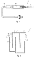
- Fig. 1 shows an isometric view of a cryosurgical instrument according to the present application.
- the instrument 1 consists of a cryoprobe holder 46 and a cryoprobe 2 which can be used therein, which according to the invention can be cooled by a configuration of a line system described in detail below in such a way that cryosurgical operations can be performed therewith.
- the cryosurgical device is equipped with gas supply means 44 which allow connection to a gas reservoir (not shown) or similar gas supply.
- Fig. 2 is a schematic representation of a first embodiment of the cryoprobe 2 can be seen.
- it is essentially designed as a cryoprobe surface which has a substantially flat, meandering line system 8 through which a cooling gas flows in a flow direction R S.
- the line system 8 is designed such that it has a widening over the flow path along the flow direction R S line cross-section and thus forms an expansion channel 12.
- the cooling gas flowing in via the inlet 3 on its way through the expansion channel 12 to a drain 5 gradually relaxes and so cooled according to the Joule-Thomson effect.
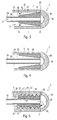
- Fig. 3-9 show further embodiments of the cryoprobe 2 according to the invention, wherein these are basically formed from a double-walled tube comprising an inner tube 19 and an outer tube 21.
- the inner tube 19 acts as an inlet 3, via which a cooling fluid can be passed through the cryoprobe 2.
- a cryoprobe tip 34 is arranged, which forms a connection between the inner channel 26 of the inner tube 19 and the outer channel 30 to form a Umlenkkanals 38, which is formed by the inner tube 19 and the outer tube 21.
- a modeling member 16 is arranged, which tapers in the flow direction R S such that a over a length l successively expanding expansion channel 12 is formed. Cooling fluid, which flows via the inlet 3 through the inner channel 26, from there via the deflection channel 38 into the expansion channel 12, there expands successively over the length l, so that it cools and thus over the heat-conductive outer wall 32 of the outer channel 30 comes to a cooling on the outside 7 of the cooling probe 2.
- cryoprobe 2 shown here is rotationally symmetrical in design from a double-walled tube with a uniformly thick outer wall 32 and a rotationally symmetrical, tapered hollow body as modeling component 12, uniform cooling occurs over the circumference of the cryoprobe 2.
- uniform cooling occurs over the circumference of the cryoprobe 2.
- Fig. 4 shows a third embodiment of the cryoprobe 2, again comprising an inner tube 19 and an outer tube 21, the channels 26 and 30 through a cryoprobe tip 34 and a resulting deflection channel 38 are in fluid communication with each other.
- a modeling member 16 to form a Expansion channel 12 used in the outer channel 30, a modeling member 16 to form a Expansion channel 12 used in the outer channel 30, a modeling member 16 to form a Expansion channel 12 used.
- the modeling component 16 is designed here as a rotationally symmetrical hollow cylinder with successively widening inner walls. In order to fix the hollow cylinder 16 in its position within the outer tube 21, this has Einsetznuten 29, which allow the perfect fit insertion.
- Fig. 5 shows a fourth embodiment of the Kryosondenspitze 2, again consisting of a double-walled tube 19, 21, in whose outer channel 30 to form the expansion channel 12, a modeling member 16 is inserted.
- this modeling component 16 comprises on a tapering wall 23 an external thread 22 which can be screwed into an internal thread 20 formed on the inner wall 28 of the outer tube 21.
- the cooling effect on the outside 7 can additionally be influenced here.
- Fig. 6 shows a fifth embodiment of the cryoprobe 2.
- the modeling member 16 is formed as a widening hollow cylinder having an internal thread 20 which is so complementary to an external thread 22 of the inner tube 18, that the modeling member 16 on the tube 19 with the formation of a helically encircling expansion channel 12 in the thread 24 of the two complementary threads 20, 22 can be screwed.
- this embodiment of the cryoprobe 2 comprises a cryoprobe tip 34, which can be screwed onto a free end 36 of the double-walled tube 19, 21 via a threaded region 35 in such a way that the size of the deflection channel 38 formed by the cryoprobe tip 34 can be screwed out or in through it the cryoprobe tip 34 is customizable.
- Fig. 7 shows a sixth embodiment of the cryoprobe 2, again comprising a double-walled tube 19, 21, wherein the inner tube 19 as the inlet 3 and the outer tube 21 and the inner tube formed between inner tube 19 and outer tube 21 30 functions as a return 5.
- a modeling component 16 is used to form an expansion channel 12, which has an external thread 22.
- the tube 21 has a complementary internal thread 20, which is designed here as a so-called opposite to the flow direction R S extending tapered thread.
- R S extending tapered thread.
- Fig. 8 shows a seventh embodiment of the cryoprobe 2, in which between a functioning as an inlet 3 inner tube 19 and an outer tube 21 on both walls 28, 32 of the tubes 19, 21 a helically extending around the inner tube 19 modeling component 16, in this case a Wire, is wound, so that between the individual windings 42, 42 'and the respective walls 28, 32 forms an expansion channel 12, which also extends again successively widening, around the inner tube 19 helically.
- a cooling fluid flowing in via the inner tube 19 or the inlet 3 in the flow direction R S then again enters this helical expansion channel 12 via a circulation channel 38, where it gradually relaxes and cools due to the successively increasing cross-section.
- the modeling component 16 or the wire can be both a component wound up independently on the inner tube 19 and a component formed integrally with this and / or the outer tube 21.
- Fig. 9 shows an eighth embodiment of the cryoprobe 2 according to the invention, which operates on the same principle, as the embodiment of Fig. 8 .
- the modeling element 16 embodied as a wire
- a corresponding notches 43 are arranged on the outer wall 32 of the outer tube 21 so that the resulting bulge 45 presses against the inner tube 19 in a fluid-tight manner. Since the notch 43 is helically and with increasing pitch applied to the outer tube 21, results between the individual turns of the notch 43 and the bulge 45 is a circumferential, successively expanding expansion channel 12 through which the gas flows along and under gradual cooling relaxed.
- FIG. 10 shows Fig. 10 in which the indentations 43 or protrusions 45 are arranged on the inner tube 19, so that the bulges 45 create a fluid-tight seal with the outer tube 21 or its wall 32, forming a corresponding expansion channel 12.
Landscapes
- Health & Medical Sciences (AREA)
- Surgery (AREA)
- Life Sciences & Earth Sciences (AREA)
- Nuclear Medicine, Radiotherapy & Molecular Imaging (AREA)
- Medical Informatics (AREA)
- Engineering & Computer Science (AREA)
- Biomedical Technology (AREA)
- Heart & Thoracic Surgery (AREA)
- Otolaryngology (AREA)
- Molecular Biology (AREA)
- Animal Behavior & Ethology (AREA)
- General Health & Medical Sciences (AREA)
- Public Health (AREA)
- Veterinary Medicine (AREA)
- Surgical Instruments (AREA)
- Sampling And Sample Adjustment (AREA)
- Thermotherapy And Cooling Therapy Devices (AREA)
Priority Applications (1)
| Application Number | Priority Date | Filing Date | Title |
|---|---|---|---|
| PL09711752T PL2257235T3 (pl) | 2008-02-21 | 2009-02-11 | Narzędzie kriochirurgiczne |
Applications Claiming Priority (2)
| Application Number | Priority Date | Filing Date | Title |
|---|---|---|---|
| DE102008010477A DE102008010477A1 (de) | 2008-02-21 | 2008-02-21 | Kryochirurgisches Instrument |
| PCT/EP2009/000956 WO2009103448A1 (de) | 2008-02-21 | 2009-02-11 | Kryochirurgisches instrument |
Publications (2)
| Publication Number | Publication Date |
|---|---|
| EP2257235A1 EP2257235A1 (de) | 2010-12-08 |
| EP2257235B1 true EP2257235B1 (de) | 2015-04-29 |
Family
ID=40668324
Family Applications (1)
| Application Number | Title | Priority Date | Filing Date |
|---|---|---|---|
| EP09711752.7A Not-in-force EP2257235B1 (de) | 2008-02-21 | 2009-02-11 | Kryochirurgisches instrument |
Country Status (7)
| Country | Link |
|---|---|
| US (1) | US8939968B2 (enExample) |
| EP (1) | EP2257235B1 (enExample) |
| JP (2) | JP2011514188A (enExample) |
| CN (1) | CN101969872B (enExample) |
| DE (1) | DE102008010477A1 (enExample) |
| PL (1) | PL2257235T3 (enExample) |
| WO (1) | WO2009103448A1 (enExample) |
Families Citing this family (13)
| Publication number | Priority date | Publication date | Assignee | Title |
|---|---|---|---|---|
| EP2632372A4 (en) * | 2010-10-27 | 2015-04-01 | Cryomedix Llc | CRYOABLATION DEVICE WITH EXTENDED HEAT EXCHANGE RANGE AND CORRESPONDING METHOD |
| CN103402449B (zh) * | 2011-03-09 | 2016-08-10 | 艾斯酷瑞医药有限公司 | 具有改向流的冷冻外科器械 |
| US10390871B2 (en) * | 2015-02-20 | 2019-08-27 | Galil Medical Inc. | Cryoneedle |
| RU167325U1 (ru) * | 2016-04-13 | 2017-01-10 | Общество с ограниченной ответственностью инновационное предприятие 'Биостандарт" (ООО ИП "Биостандарт") | Устройство для локальной криотерапии |
| CN106052179A (zh) * | 2016-06-08 | 2016-10-26 | 西安交通大学 | 一种波纹管自调式节流制冷器 |
| WO2019071269A2 (en) | 2017-10-06 | 2019-04-11 | Powell Charles Lee | SYSTEM AND METHOD FOR TREATING AN OBSTRUCTIVE SLEEP APNEA |
| WO2019092613A1 (en) | 2017-11-13 | 2019-05-16 | Biocompatibles Uk Limited | Cryoprobe for magnetic resonance imaging |
| AU2018364675B2 (en) | 2017-11-13 | 2021-11-04 | Biocompatibles Uk Limited | Cryoablation system with magnetic resonance imaging detection |
| JP2022527172A (ja) * | 2019-03-25 | 2022-05-31 | バイオコンパティブルズ ユーケー リミテッド | クライオプローブ |
| EP3769706A1 (de) | 2019-07-23 | 2021-01-27 | Erbe Elektromedizin GmbH | Kryosonde |
| CN112213069B (zh) * | 2020-10-12 | 2022-06-10 | 中国空气动力研究与发展中心超高速空气动力研究所 | 一种用于高超声速高温风洞具有冷却结构的流场校测排架 |
| CN113143580B (zh) * | 2021-04-07 | 2022-11-18 | 深圳市眼科医院 | 一种采用氟利昂的笔式纤巧冷冻装置 |
| CN114288528B (zh) * | 2021-12-31 | 2024-07-19 | 科睿驰(深圳)医疗科技发展有限公司 | 一种球囊微导管及其制备方法 |
Citations (1)
| Publication number | Priority date | Publication date | Assignee | Title |
|---|---|---|---|---|
| US20030023288A1 (en) * | 1999-02-09 | 2003-01-30 | Michael Magers | Method and device for patient temperature control employing optimized rewarming |
Family Cites Families (12)
| Publication number | Priority date | Publication date | Assignee | Title |
|---|---|---|---|---|
| US3613689A (en) * | 1970-01-13 | 1971-10-19 | Frigitronics Of Conn Inc | Cryosurgical apparatus |
| DE2831199C3 (de) * | 1978-07-15 | 1981-01-08 | Erbe Elektromedizin Gmbh & Co Kg, 7400 Tuebingen | Kryochirurgiegerät |
| US5254116A (en) * | 1991-09-06 | 1993-10-19 | Cryomedical Sciences, Inc. | Cryosurgical instrument with vent holes and method using same |
| GB2283678B (en) * | 1993-11-09 | 1998-06-03 | Spembly Medical Ltd | Cryosurgical catheter probe |
| US5901783A (en) | 1995-10-12 | 1999-05-11 | Croyogen, Inc. | Cryogenic heat exchanger |
| US6669689B2 (en) * | 1997-02-27 | 2003-12-30 | Cryocath Technologies Inc. | Cryosurgical catheter |
| US7591814B2 (en) * | 1997-02-27 | 2009-09-22 | Cryocath Technologies Inc. | Extended treatment zone catheter |
| GB2336781B (en) * | 1998-04-30 | 2001-03-07 | Spembly Medical Ltd | Cryosurgical apparatus |
| US6270493B1 (en) * | 1999-07-19 | 2001-08-07 | Cryocath Technologies, Inc. | Cryoablation structure |
| WO2001016017A1 (en) * | 1999-08-31 | 2001-03-08 | The Coca-Cola Company | Heat exchanger for beverage dispenser |
| US6858025B2 (en) * | 2002-08-06 | 2005-02-22 | Medically Advanced Designs, Llc | Cryo-surgical apparatus and method of use |
| US7160291B2 (en) * | 2003-06-25 | 2007-01-09 | Endocare, Inc. | Detachable cryosurgical probe |
-
2008
- 2008-02-21 DE DE102008010477A patent/DE102008010477A1/de not_active Withdrawn
-
2009
- 2009-02-11 PL PL09711752T patent/PL2257235T3/pl unknown
- 2009-02-11 US US12/918,587 patent/US8939968B2/en not_active Expired - Fee Related
- 2009-02-11 JP JP2010547082A patent/JP2011514188A/ja active Pending
- 2009-02-11 WO PCT/EP2009/000956 patent/WO2009103448A1/de not_active Ceased
- 2009-02-11 CN CN2009801058401A patent/CN101969872B/zh not_active Expired - Fee Related
- 2009-02-11 EP EP09711752.7A patent/EP2257235B1/de not_active Not-in-force
-
2013
- 2013-12-19 JP JP2013262668A patent/JP5925754B2/ja not_active Expired - Fee Related
Patent Citations (1)
| Publication number | Priority date | Publication date | Assignee | Title |
|---|---|---|---|---|
| US20030023288A1 (en) * | 1999-02-09 | 2003-01-30 | Michael Magers | Method and device for patient temperature control employing optimized rewarming |
Also Published As
| Publication number | Publication date |
|---|---|
| CN101969872B (zh) | 2013-09-25 |
| JP2014131734A (ja) | 2014-07-17 |
| US8939968B2 (en) | 2015-01-27 |
| WO2009103448A1 (de) | 2009-08-27 |
| US20110022040A1 (en) | 2011-01-27 |
| PL2257235T3 (pl) | 2015-10-30 |
| CN101969872A (zh) | 2011-02-09 |
| JP2011514188A (ja) | 2011-05-06 |
| EP2257235A1 (de) | 2010-12-08 |
| DE102008010477A1 (de) | 2009-09-03 |
| JP5925754B2 (ja) | 2016-05-25 |
Similar Documents
| Publication | Publication Date | Title |
|---|---|---|
| EP2257235B1 (de) | Kryochirurgisches instrument | |
| DE69423295T2 (de) | Katheter zur Kryo-Abtragung | |
| DE2831199C3 (de) | Kryochirurgiegerät | |
| DE102008024946B4 (de) | Kryochirurgisches Instrument zur Gewinnung einer Gewebeprobe | |
| DE102010033153B4 (de) | Spritzgießdüse | |
| EP2996596A1 (de) | Medizinischer katheter zur hypothermischen behandlung, behandlungssystem mit einem derartigen katheter und herstellungsverfahren | |
| DE1541099B2 (de) | Kaeltechirurgisches instrument | |
| EP4215137B1 (de) | Kryochirurgisches instrument | |
| DE202007006682U1 (de) | Erdwärmesonde | |
| DE202010011404U1 (de) | Elektrische Heizvorrichtung | |
| DE3046471A1 (de) | Duesenkern zum einbau in einen duesenkoerper von heisskanalspritzduesen fuer eine kunststoffspritzgiessvorrichtung | |
| DE102011080315B4 (de) | Heizvorrichtung mit Temperaturfühler | |
| WO2020216619A1 (de) | Extrusionszylinder mit kühl- bzw. heizmittelführung | |
| EP1646323B1 (de) | Chirurgische sonde | |
| EP3049735A1 (de) | Speichersonde mit vermischungskörpern | |
| DE102008028728A1 (de) | Wärmetauscher zum Erwärmen eines tiefkalten Fluids | |
| WO2023209121A1 (de) | Medizinisches kryotherapie-gerät mit wärmeübertragungskörper | |
| DE102009025165A1 (de) | Spritzgießvorrichtung, Spritzgießdüse und Verteiler | |
| EP0548021B1 (de) | Kühlvorrichtung | |
| WO2017005830A1 (de) | Elektrochirurgisches instrument für die argon-plasma-koagulation und verfahren zum betreiben | |
| DE102007009027A1 (de) | Schnecke mit Wärmetransportvorrichtung | |
| EP4042056B1 (de) | Beheizbare fluidleitung mit interner und externer heizeinrichtung | |
| DE10251449A1 (de) | Kryostat | |
| AT406806B (de) | Einrichtung an einer extrusionsanlage | |
| DE1094767B (de) | Wirbelrohr zum Erzeugen von Kaelte |
Legal Events
| Date | Code | Title | Description |
|---|---|---|---|
| PUAI | Public reference made under article 153(3) epc to a published international application that has entered the european phase |
Free format text: ORIGINAL CODE: 0009012 |
|
| 17P | Request for examination filed |
Effective date: 20100917 |
|
| AK | Designated contracting states |
Kind code of ref document: A1 Designated state(s): AT BE BG CH CY CZ DE DK EE ES FI FR GB GR HR HU IE IS IT LI LT LU LV MC MK MT NL NO PL PT RO SE SI SK TR |
|
| AX | Request for extension of the european patent |
Extension state: AL BA RS |
|
| DAX | Request for extension of the european patent (deleted) | ||
| 17Q | First examination report despatched |
Effective date: 20130222 |
|
| GRAP | Despatch of communication of intention to grant a patent |
Free format text: ORIGINAL CODE: EPIDOSNIGR1 |
|
| INTG | Intention to grant announced |
Effective date: 20141127 |
|
| GRAS | Grant fee paid |
Free format text: ORIGINAL CODE: EPIDOSNIGR3 |
|
| GRAA | (expected) grant |
Free format text: ORIGINAL CODE: 0009210 |
|
| AK | Designated contracting states |
Kind code of ref document: B1 Designated state(s): AT BE BG CH CY CZ DE DK EE ES FI FR GB GR HR HU IE IS IT LI LT LU LV MC MK MT NL NO PL PT RO SE SI SK TR |
|
| REG | Reference to a national code |
Ref country code: GB Ref legal event code: FG4D Free format text: NOT ENGLISH |
|
| REG | Reference to a national code |
Ref country code: CH Ref legal event code: EP |
|
| REG | Reference to a national code |
Ref country code: AT Ref legal event code: REF Ref document number: 724004 Country of ref document: AT Kind code of ref document: T Effective date: 20150515 |
|
| REG | Reference to a national code |
Ref country code: IE Ref legal event code: FG4D Free format text: LANGUAGE OF EP DOCUMENT: GERMAN |
|
| REG | Reference to a national code |
Ref country code: DE Ref legal event code: R096 Ref document number: 502009010960 Country of ref document: DE Effective date: 20150603 |
|
| REG | Reference to a national code |
Ref country code: NL Ref legal event code: VDEP Effective date: 20150429 |
|
| REG | Reference to a national code |
Ref country code: LT Ref legal event code: MG4D |
|
| PG25 | Lapsed in a contracting state [announced via postgrant information from national office to epo] |
Ref country code: NL Free format text: LAPSE BECAUSE OF FAILURE TO SUBMIT A TRANSLATION OF THE DESCRIPTION OR TO PAY THE FEE WITHIN THE PRESCRIBED TIME-LIMIT Effective date: 20150429 |
|
| PG25 | Lapsed in a contracting state [announced via postgrant information from national office to epo] |
Ref country code: LT Free format text: LAPSE BECAUSE OF FAILURE TO SUBMIT A TRANSLATION OF THE DESCRIPTION OR TO PAY THE FEE WITHIN THE PRESCRIBED TIME-LIMIT Effective date: 20150429 Ref country code: PT Free format text: LAPSE BECAUSE OF FAILURE TO SUBMIT A TRANSLATION OF THE DESCRIPTION OR TO PAY THE FEE WITHIN THE PRESCRIBED TIME-LIMIT Effective date: 20150831 Ref country code: ES Free format text: LAPSE BECAUSE OF FAILURE TO SUBMIT A TRANSLATION OF THE DESCRIPTION OR TO PAY THE FEE WITHIN THE PRESCRIBED TIME-LIMIT Effective date: 20150429 Ref country code: HR Free format text: LAPSE BECAUSE OF FAILURE TO SUBMIT A TRANSLATION OF THE DESCRIPTION OR TO PAY THE FEE WITHIN THE PRESCRIBED TIME-LIMIT Effective date: 20150429 Ref country code: NO Free format text: LAPSE BECAUSE OF FAILURE TO SUBMIT A TRANSLATION OF THE DESCRIPTION OR TO PAY THE FEE WITHIN THE PRESCRIBED TIME-LIMIT Effective date: 20150729 Ref country code: FI Free format text: LAPSE BECAUSE OF FAILURE TO SUBMIT A TRANSLATION OF THE DESCRIPTION OR TO PAY THE FEE WITHIN THE PRESCRIBED TIME-LIMIT Effective date: 20150429 |
|
| REG | Reference to a national code |
Ref country code: PL Ref legal event code: T3 |
|
| PG25 | Lapsed in a contracting state [announced via postgrant information from national office to epo] |
Ref country code: LV Free format text: LAPSE BECAUSE OF FAILURE TO SUBMIT A TRANSLATION OF THE DESCRIPTION OR TO PAY THE FEE WITHIN THE PRESCRIBED TIME-LIMIT Effective date: 20150429 Ref country code: IS Free format text: LAPSE BECAUSE OF FAILURE TO SUBMIT A TRANSLATION OF THE DESCRIPTION OR TO PAY THE FEE WITHIN THE PRESCRIBED TIME-LIMIT Effective date: 20150829 Ref country code: GR Free format text: LAPSE BECAUSE OF FAILURE TO SUBMIT A TRANSLATION OF THE DESCRIPTION OR TO PAY THE FEE WITHIN THE PRESCRIBED TIME-LIMIT Effective date: 20150730 |
|
| PG25 | Lapsed in a contracting state [announced via postgrant information from national office to epo] |
Ref country code: EE Free format text: LAPSE BECAUSE OF FAILURE TO SUBMIT A TRANSLATION OF THE DESCRIPTION OR TO PAY THE FEE WITHIN THE PRESCRIBED TIME-LIMIT Effective date: 20150429 Ref country code: DK Free format text: LAPSE BECAUSE OF FAILURE TO SUBMIT A TRANSLATION OF THE DESCRIPTION OR TO PAY THE FEE WITHIN THE PRESCRIBED TIME-LIMIT Effective date: 20150429 |
|
| REG | Reference to a national code |
Ref country code: DE Ref legal event code: R097 Ref document number: 502009010960 Country of ref document: DE |
|
| PG25 | Lapsed in a contracting state [announced via postgrant information from national office to epo] |
Ref country code: SK Free format text: LAPSE BECAUSE OF FAILURE TO SUBMIT A TRANSLATION OF THE DESCRIPTION OR TO PAY THE FEE WITHIN THE PRESCRIBED TIME-LIMIT Effective date: 20150429 Ref country code: RO Free format text: LAPSE BECAUSE OF NON-PAYMENT OF DUE FEES Effective date: 20150429 Ref country code: CZ Free format text: LAPSE BECAUSE OF FAILURE TO SUBMIT A TRANSLATION OF THE DESCRIPTION OR TO PAY THE FEE WITHIN THE PRESCRIBED TIME-LIMIT Effective date: 20150429 |
|
| REG | Reference to a national code |
Ref country code: FR Ref legal event code: PLFP Year of fee payment: 8 |
|
| PLBE | No opposition filed within time limit |
Free format text: ORIGINAL CODE: 0009261 |
|
| STAA | Information on the status of an ep patent application or granted ep patent |
Free format text: STATUS: NO OPPOSITION FILED WITHIN TIME LIMIT |
|
| 26N | No opposition filed |
Effective date: 20160201 |
|
| PG25 | Lapsed in a contracting state [announced via postgrant information from national office to epo] |
Ref country code: BE Free format text: LAPSE BECAUSE OF NON-PAYMENT OF DUE FEES Effective date: 20160229 Ref country code: SI Free format text: LAPSE BECAUSE OF FAILURE TO SUBMIT A TRANSLATION OF THE DESCRIPTION OR TO PAY THE FEE WITHIN THE PRESCRIBED TIME-LIMIT Effective date: 20150429 |
|
| PG25 | Lapsed in a contracting state [announced via postgrant information from national office to epo] |
Ref country code: MC Free format text: LAPSE BECAUSE OF FAILURE TO SUBMIT A TRANSLATION OF THE DESCRIPTION OR TO PAY THE FEE WITHIN THE PRESCRIBED TIME-LIMIT Effective date: 20150429 Ref country code: LU Free format text: LAPSE BECAUSE OF FAILURE TO SUBMIT A TRANSLATION OF THE DESCRIPTION OR TO PAY THE FEE WITHIN THE PRESCRIBED TIME-LIMIT Effective date: 20160211 |
|
| REG | Reference to a national code |
Ref country code: CH Ref legal event code: PL |
|
| PG25 | Lapsed in a contracting state [announced via postgrant information from national office to epo] |
Ref country code: CH Free format text: LAPSE BECAUSE OF NON-PAYMENT OF DUE FEES Effective date: 20160229 Ref country code: LI Free format text: LAPSE BECAUSE OF NON-PAYMENT OF DUE FEES Effective date: 20160229 |
|
| REG | Reference to a national code |
Ref country code: IE Ref legal event code: MM4A |
|
| PG25 | Lapsed in a contracting state [announced via postgrant information from national office to epo] |
Ref country code: IE Free format text: LAPSE BECAUSE OF NON-PAYMENT OF DUE FEES Effective date: 20160211 |
|
| REG | Reference to a national code |
Ref country code: FR Ref legal event code: PLFP Year of fee payment: 9 |
|
| REG | Reference to a national code |
Ref country code: AT Ref legal event code: MM01 Ref document number: 724004 Country of ref document: AT Kind code of ref document: T Effective date: 20160211 |
|
| PG25 | Lapsed in a contracting state [announced via postgrant information from national office to epo] |
Ref country code: AT Free format text: LAPSE BECAUSE OF NON-PAYMENT OF DUE FEES Effective date: 20160211 |
|
| PG25 | Lapsed in a contracting state [announced via postgrant information from national office to epo] |
Ref country code: SE Free format text: LAPSE BECAUSE OF FAILURE TO SUBMIT A TRANSLATION OF THE DESCRIPTION OR TO PAY THE FEE WITHIN THE PRESCRIBED TIME-LIMIT Effective date: 20150429 |
|
| PG25 | Lapsed in a contracting state [announced via postgrant information from national office to epo] |
Ref country code: MT Free format text: LAPSE BECAUSE OF FAILURE TO SUBMIT A TRANSLATION OF THE DESCRIPTION OR TO PAY THE FEE WITHIN THE PRESCRIBED TIME-LIMIT Effective date: 20150429 |
|
| REG | Reference to a national code |
Ref country code: FR Ref legal event code: PLFP Year of fee payment: 10 |
|
| PG25 | Lapsed in a contracting state [announced via postgrant information from national office to epo] |
Ref country code: CY Free format text: LAPSE BECAUSE OF FAILURE TO SUBMIT A TRANSLATION OF THE DESCRIPTION OR TO PAY THE FEE WITHIN THE PRESCRIBED TIME-LIMIT Effective date: 20150429 Ref country code: HU Free format text: LAPSE BECAUSE OF FAILURE TO SUBMIT A TRANSLATION OF THE DESCRIPTION OR TO PAY THE FEE WITHIN THE PRESCRIBED TIME-LIMIT; INVALID AB INITIO Effective date: 20090211 |
|
| PG25 | Lapsed in a contracting state [announced via postgrant information from national office to epo] |
Ref country code: TR Free format text: LAPSE BECAUSE OF FAILURE TO SUBMIT A TRANSLATION OF THE DESCRIPTION OR TO PAY THE FEE WITHIN THE PRESCRIBED TIME-LIMIT Effective date: 20150429 Ref country code: MK Free format text: LAPSE BECAUSE OF FAILURE TO SUBMIT A TRANSLATION OF THE DESCRIPTION OR TO PAY THE FEE WITHIN THE PRESCRIBED TIME-LIMIT Effective date: 20150429 |
|
| PG25 | Lapsed in a contracting state [announced via postgrant information from national office to epo] |
Ref country code: BG Free format text: LAPSE BECAUSE OF FAILURE TO SUBMIT A TRANSLATION OF THE DESCRIPTION OR TO PAY THE FEE WITHIN THE PRESCRIBED TIME-LIMIT Effective date: 20150429 |
|
| PGFP | Annual fee paid to national office [announced via postgrant information from national office to epo] |
Ref country code: FR Payment date: 20210223 Year of fee payment: 13 Ref country code: IT Payment date: 20210223 Year of fee payment: 13 |
|
| PGFP | Annual fee paid to national office [announced via postgrant information from national office to epo] |
Ref country code: GB Payment date: 20210223 Year of fee payment: 13 Ref country code: PL Payment date: 20210125 Year of fee payment: 13 |
|
| PGFP | Annual fee paid to national office [announced via postgrant information from national office to epo] |
Ref country code: DE Payment date: 20210329 Year of fee payment: 13 |
|
| REG | Reference to a national code |
Ref country code: DE Ref legal event code: R119 Ref document number: 502009010960 Country of ref document: DE |
|
| GBPC | Gb: european patent ceased through non-payment of renewal fee |
Effective date: 20220211 |
|
| PG25 | Lapsed in a contracting state [announced via postgrant information from national office to epo] |
Ref country code: FR Free format text: LAPSE BECAUSE OF NON-PAYMENT OF DUE FEES Effective date: 20220228 |
|
| PG25 | Lapsed in a contracting state [announced via postgrant information from national office to epo] |
Ref country code: GB Free format text: LAPSE BECAUSE OF NON-PAYMENT OF DUE FEES Effective date: 20220211 Ref country code: DE Free format text: LAPSE BECAUSE OF NON-PAYMENT OF DUE FEES Effective date: 20220901 |
|
| PG25 | Lapsed in a contracting state [announced via postgrant information from national office to epo] |
Ref country code: PL Free format text: LAPSE BECAUSE OF NON-PAYMENT OF DUE FEES Effective date: 20220211 Ref country code: IT Free format text: LAPSE BECAUSE OF NON-PAYMENT OF DUE FEES Effective date: 20220211 |