EP2256691A1 - Dispositif de traitement d'image pour véhicule et programme de traitement d'image - Google Patents
Dispositif de traitement d'image pour véhicule et programme de traitement d'image Download PDFInfo
- Publication number
- EP2256691A1 EP2256691A1 EP09723985A EP09723985A EP2256691A1 EP 2256691 A1 EP2256691 A1 EP 2256691A1 EP 09723985 A EP09723985 A EP 09723985A EP 09723985 A EP09723985 A EP 09723985A EP 2256691 A1 EP2256691 A1 EP 2256691A1
- Authority
- EP
- European Patent Office
- Prior art keywords
- image
- pixel
- pixel value
- value
- kernel
- Prior art date
- Legal status (The legal status is an assumption and is not a legal conclusion. Google has not performed a legal analysis and makes no representation as to the accuracy of the status listed.)
- Granted
Links
- 238000009499 grossing Methods 0.000 claims abstract description 101
- 238000001914 filtration Methods 0.000 claims abstract description 10
- 238000000034 method Methods 0.000 claims description 76
- 238000003384 imaging method Methods 0.000 abstract 1
- 230000014509 gene expression Effects 0.000 description 11
- 238000010586 diagram Methods 0.000 description 10
- 230000000694 effects Effects 0.000 description 5
- 230000006870 function Effects 0.000 description 5
- 238000006243 chemical reaction Methods 0.000 description 3
- 241001085205 Prenanthella exigua Species 0.000 description 2
- 239000000284 extract Substances 0.000 description 2
- 238000000605 extraction Methods 0.000 description 2
- 238000001514 detection method Methods 0.000 description 1
- 230000001747 exhibiting effect Effects 0.000 description 1
- 230000000717 retained effect Effects 0.000 description 1
- 239000007787 solid Substances 0.000 description 1
- 230000001131 transforming effect Effects 0.000 description 1
- 230000001755 vocal effect Effects 0.000 description 1
Images


Classifications
-
- G06T5/70—
-
- G—PHYSICS
- G06—COMPUTING; CALCULATING OR COUNTING
- G06T—IMAGE DATA PROCESSING OR GENERATION, IN GENERAL
- G06T5/00—Image enhancement or restoration
-
- G—PHYSICS
- G06—COMPUTING; CALCULATING OR COUNTING
- G06T—IMAGE DATA PROCESSING OR GENERATION, IN GENERAL
- G06T7/00—Image analysis
- G06T7/60—Analysis of geometric attributes
-
- G—PHYSICS
- G06—COMPUTING; CALCULATING OR COUNTING
- G06V—IMAGE OR VIDEO RECOGNITION OR UNDERSTANDING
- G06V20/00—Scenes; Scene-specific elements
- G06V20/50—Context or environment of the image
- G06V20/56—Context or environment of the image exterior to a vehicle by using sensors mounted on the vehicle
- G06V20/588—Recognition of the road, e.g. of lane markings; Recognition of the vehicle driving pattern in relation to the road
-
- G—PHYSICS
- G06—COMPUTING; CALCULATING OR COUNTING
- G06T—IMAGE DATA PROCESSING OR GENERATION, IN GENERAL
- G06T2207/00—Indexing scheme for image analysis or image enhancement
- G06T2207/10—Image acquisition modality
- G06T2207/10016—Video; Image sequence
-
- G—PHYSICS
- G06—COMPUTING; CALCULATING OR COUNTING
- G06T—IMAGE DATA PROCESSING OR GENERATION, IN GENERAL
- G06T2207/00—Indexing scheme for image analysis or image enhancement
- G06T2207/30—Subject of image; Context of image processing
- G06T2207/30248—Vehicle exterior or interior
- G06T2207/30252—Vehicle exterior; Vicinity of vehicle
- G06T2207/30256—Lane; Road marking
Definitions
- the present invention relates to a vehicular image processing device for processing an image of the circumference of a vehicle acquired by a photographing unit, and a vehicular image processing program causing a computer to perform the mentioned process.
- the vehicular circumference recognizing device of the conventional art receives an image of the front side of the vehicle photographed by a camera mounted in the vehicle, sets a window for the processing subject in the image, sets the color of a lower portion of the window as the reference color for a road surface area (an area except the white line inside the road), sets an area with color similar to (color similarity is greater than a predefined value) the reference color as the road surface area, and differentiates the road surface area from the non-road surface area (the white line or the non-road area). Thereafter, the device performs detection of the white line, namely detects a straight line obtained respectively from the left and right boundaries of the differentiated road surface area as an edge portion of the white line.
- the window is set to a single one in the image according to the positions of the two white lines detected in the previous processing cycle, or according to a fixed value set on the basis of a predefined road information such as the width of a road or the width of a travel lane.
- a repaired position or a local shadow may be left on the road surface.
- the repaired position has color locally different from the ambient road surface.
- the local shadow portion due to the color further added according to the scattering light only, may have color deviated from the ambient road surface.
- the local repaired position or the local shadow portion in the window may be differentiated as the non-road surface area due to the deviation of color from the reference color. Since the white line is detected according to the boundary therebetween, the white line may be detected with error. In the case of using luminance instead of color, the same result will be obtained.
- the color of a road surface may vary in the road surface area, for example, when time passes or the color thereof is not identically defined by government.
- the color of a road surface may vary in the road surface area, for example, when time passes or the color thereof is not identically defined by government.
- a wide partial area with color different from the ambient area is present in the road surface area.
- the device in the conventional art mentioned above it is difficult for the device in the conventional art mentioned above to use the color of the lower portion in the window as the reference color of the road surface to differentiate the road surface area from the non-road surface area.
- the color in the road surface area is not identical, it is difficult to set the reference color and the conditions for defining a color similar to the reference color appropriately.
- the setting is loose, the lane mark will be included in the road surface area; on the other hand, if the setting is strict, the portion area will be differentiated as the non-road surface area. Thereby, the boundary between the road surface area and the non-road surface area will be obtained with error. Since the white line or a proceeding vehicle is detected according to the boundary obtained with error, the white line or the proceeding vehicle may be detected with error. In the case of using luminance instead of color, the same result will be obtained.
- the present invention has been accomplished in view of the aforementioned problems, and it is therefore an object of the present invention to provide a vehicular image processing device capable of processing a photographed image of the circumference of a vehicle to reduce influences from variation of luminance and color of a road surface so as to detect a lane mark on a road where the vehicle is travelling precisely from the processed image.
- the vehicular image processing device of the present invention is configured to process an image acquired from a photographing unit mounted in a vehicle and detect a lane mark on a road where the vehicle is travelling from the processed image.
- the vehicular image processing device of the present invention comprises: a kernel setting unit configured to set a kernel size for the image acquired from the photographing device so that the width of the kernel in a predefined direction is in a predefined range greater than the width of an image portion of the lane mark in the predefined direction; a smoothing unit configured to smooth the acquired image according to a filtering process by the usage of the smoothing kernel size set by the kernel setting unit; a variation degree calculating unit configured to calculate a variation degree of the pixel value of each pixel in the acquired image with respect to the smoothed image processed by the smoothing unit; a pixel value replacing unit configured to replace the pixel value of the acquired image with a specific value if the variation degree is equal to or smaller than a predefined value; and a lane mark detecting unit configured to detect the lane
- the kernel size is set by the kernel setting unit and the acquired image is smoothed by the smoothing unit according to a filtering process by the usage of a smoothing kernel with the set size.
- a smoothing kernel is disposed with a pixel as the central pixel, and a process is performed to set the average of pixel value of all pixels contained in the range of smoothing kernel equal to the pixel value of the central pixel. According thereto, the variation width of the pixels in the image becomes narrower, and a low-contrast image can be obtained.
- the image of the road is smoothed by using the kernel size set by the kernel setting unit in such a way that the width in a predefined direction is in a predefined range greater than the width of an image portion of the lane mark in the predefined direction.
- the size of the image portion of the road surface and the partial area is greater than that of the image portion of the lane mark.
- the variation degree of the pixel value for each pixel in the acquired image with respect to the smoothed image processed by the smoothing unit is calculated by the variation degree calculating unit, for the image portion of the lane mark with a greater pixel value than the image portion of the road surface, the variation degree is a great positive value; for the image portion of the local repaired position or shadow with a smaller pixel value than the image portion of the road surface, the variation degree is a small value (including negative values).
- the variation degree therebetween is a small value (including negative values).
- the pixel value of the pixel with the variation degree equal to or smaller than the predefined value in the acquired image is replaced with the specific value by the pixel value replacing unit.
- the specific value is a fixed value preliminarily defined (for example, the pixel value of the image portion of the lane mark is given to a value sufficiently smaller than it should have, for example zero), or is a pixel value of a pixel corresponded to the pixel in the smoothed image with the variation degree equal to or smaller than the predefined value.
- the pixel value of the pixels in the image portion of the road surface including the partial area with a pixel value different from the ambient area or the pixel value of the pixels in the image portion of the local repaired position or shadow is replaced with the specific value, and the pixel value of the pixels in the image portion of the lane mark is remained.
- the image with the pixel value replaced by the pixel value replacing unit the image portion of the lane mark is remained, and the lane mark is detected by the lane mark detecting unit on the basis of the replaced image. Consequently, the lane mark can be detected precisely.
- the kernel setting unit sets the kernel size in such a way that the kernel size for an image portion in the image corresponded to a predefined area on the road is set smaller as a distance from the vehicle to the predefined area on the road is becoming greater.
- the kernel size is set in such a way that the kernel size for an image portion in the image corresponded to a predefined area on the road is set smaller as a distance from the vehicle to the predefined area on the road is becoming greater.
- the kernel setting unit sets the kernel to a rectangular shape or a trapezoidal shape.
- the lane mark such as the white line or yellow line on the road where the vehicle is travelling is of a linear shape.
- the smoothing kernel is set to a rectangular shape or a trapezoidal shape, it is possible to dispose the smoothing kernel to match the shape of the image portion of the lane mark.
- the kernel setting unit sets the direction of the kernel in such a way that the inclination of the center line of the long side of the rectangular shape or the trapezoidal shape of the kernel with respect to the direction corresponded to the travelling direction of the vehicle in the image is equal to a predefined angle.
- the lane mark on a road where the vehicle is travelling is photographed toward a disappearing point along the direction corresponded to the travelling direction of the vehicle in the image.
- the direction of the kernel in such a way that the inclination of the center line of the long side of the kernel with respect to the direction corresponded to the travelling direction of the vehicle in the image is equal to a predefined angle, it is possible to set the smoothing kernel in accordance with the direction of the image portion of the lane mark.
- the variation degree calculating unit calculates a difference of pixel value of each pixel obtained by subtracting the pixel value of each pixel in the smoothed image from the pixel value of each pixel in the acquired image or a ratio of pixel value of each pixel obtained by dividing the pixel value of each pixel in the acquired image by the pixel value of each pixel in the smoothed image as the variation degree.
- the difference of pixel value of each pixel obtained by subtracting the pixel value of each pixel in the smoothed image from the pixel value of each pixel in the acquired image or the ratio of pixel value of each pixel obtained by dividing the pixel value of each pixel in the acquired image by the pixel value of each pixel in the smoothed image is a value indicating the variation degree, thereby, by using the difference or the ratio, it is possible to replace appropriately the pixel value of the image by the pixel value replacing unit.
- luminance is used as the pixel value in the smoothed image processed by the smoothing unit.
- the image portion of the lane mark with a bright white or yellow color, the image portion of the road surface with a dark gray or brown color, and the image portion of the local repaired position or shadow with even darker color have different luminance.
- the luminance is used as the pixel value in the image, by replacing the pixel value so as to remove the image portion of the local repaired position or shadow while remain the image portion of the lane mark, the image portion of the lane mark can be detected from the replaced image precisely.
- luminance or saturation calculated from color components of a color image is used as the pixel value in the smoothed image processed by the smoothing unit.
- the image portion of the lane mark with a bright white or yellow color, the image portion of the road surface with a dark gray or brown color, and the image portion of the local repaired position or shadow with even darker color have different luminance.
- the luminance or the saturation is used as the pixel value in the image, by replacing the pixel value so as to remove the image portion of the local repaired position or shadow while remain the image portion of the lane mark, the image portion of the lane mark can be detected from the replaced image precisely.
- the lane mark detecting unit detects an area composed of pixels of pixel value not equal to the fixed value in the replaced image by the pixel value replacing unit as an image portion corresponded to the lane mark on the road where the vehicle is travelling.
- the pixel value of the image portion except the lane mark is replaced with the fixed value in the replaced image, thus, the area composed of pixels with the pixel value not equal to the fixed value in the replaced image can be detected as the image portion of the lane mark by the lane mark detecting unit.
- the lane mark on a road where the vehicle is travelling can be easily detected by the lane mark detecting unit even without performing an edge extraction process or the like.
- the present invention provides a vehicle which is provided with a photographing unit and has a function of processing an image acquired from the photographing unit and detecting a lane mark on a road where the vehicle is travelling.
- the vehicle of the present invention is further provided with a kernel setting unit configured to set a kernel size for the image acquired from the photographing device so that the width of the kernel in a predefined direction is in a predefined range greater than the width of an image portion of the lane mark in the predefined direction; a smoothing unit configured to smooth the acquired image according to a filtering process by the usage of the smoothing kernel size set by the kernel setting unit; a variation degree calculating unit configured to calculate a variation degree of the pixel value of each pixel in the acquired image with respect to the smoothed image processed by the smoothing unit; a pixel value replacing unit configured to replace the pixel value of the acquired image with a specific value if the variation degree is equal to or smaller than a predefined value; and a lane mark detecting unit configured to detect the lane mark from the image with the pixel value replaced by the pixel value replacing unit.
- a kernel setting unit configured to set a kernel size for the image acquired from the photographing device so that the width of the kernel in a predefined
- the specific value is a fixed value preliminarily defined (for example, the pixel value of the image portion of the lane mark is given to a value sufficiently smaller than it should have, for example zero), or a pixel value of a pixel corresponded to the pixel in the smoothed image with the variation degree equal to or smaller than the predefined value.
- the kernel size is set by the kernel setting unit in such a way that the width in a predefined direction is in a predefined range greater than the width of the image portion of the lane mark in the predefined direction, and the acquired image is smoothed by the smoothing unit according to a filtering process by the usage of the smoothing kernel with the set size. Consequently, in the smoothed image, the pixel value of the pixels constituting the image portion of the local repaired position or shadow portion or constituting the image portion of the lane mark on the road surface becomes approximate to the pixel value of the pixels constituting the image portion of the ambient road surface. Additionally, the pixel values for the image portion of the road surface and the wide partial area with a pixel value different from the ambient area in the image portion of the road surface are retained in the smoothed image the same as that in the image before smoothed.
- the pixel value of the pixels in the image portion of the road surface including the partial area with a pixel value different from the ambient area or the pixel value of the pixels in the image portion of the local repaired position or shadow is replaced with the specific value, and the pixel value of the pixels in the image portion of the lane mark is remained and the lane mark is detected by the lane mark detecting unit on the basis of the replaced image.
- the lane mark can be detected precisely.
- the present invention further provides a vehicular image processing program configured to cause a computer to process an image acquired from a photographing unit mounted in a vehicle and detect a lane mark on a road where the vehicle is travelling from the processed image.
- the computer is caused to execute: a kernel setting process configured to set a kernel size for the image acquired from the photographing device so that the width of the kernel in a predefined direction is in a predefined range greater than the width of an image portion of the lane mark in the predefined direction; a smoothing process configured to smooth the acquired image according to a filtering process by the usage of the smoothing kernel size set by the kernel setting process; a variation degree calculating process configured to calculate a variation degree of the pixel value of each pixel between the acquired image and the image smoothed by the smoothing process; a pixel value replacing process configured to replace the pixel value of the acquired image with a specific value if the variation degree is equal to or smaller than a predefined value; and a lane mark detecting process configured to detect the lane mark from the image with the pixel value replaced by the pixel value replacing process.
- a kernel setting process configured to set a kernel size for the image acquired from the photographing device so that the width of the kernel in a predefined direction is in a pre
- the specific value is a fixed value preliminarily defined (for example, the pixel value of the image portion of the lane mark is given to a value sufficiently smaller than it should have, for example zero), or a pixel value of a pixel corresponded to the pixel in the smoothed image with the variation degree equal to or smaller than the predefined value.
- the process exhibiting the effects described in the vehicular image processing device of the present invention can be made to be executed in the computer.
- a vehicular image processing device 10 of the present embodiment is mounted in a vehicle 1 for use.
- the vehicle 1 mounted with the vehicular image processing device 10 is equivalent to the vehicle of the present invention.
- the vehicular image processing device 10 detects a lane mark on a road where the vehicle 1 is travelling according to an image photographed by a camera 2 for photographing the front side of the vehicle 1.
- the camera 2 which is equivalent to the photographing unit of the present invention is composed of a CCD camera or other photographing elements and is disposed at a front portion of the vehicle 1.
- Position data of a lane mark detected by the vehicular image processing device 10 is output to an ECU (Electronic Control Unit) 20 disposed in the vehicle 1.
- the ECU 20 recognizes traffic lines of the road where the vehicle 1 is travelling according to the position data of the lane mark, and performs a traffic line deviation determining process configured to determine a possibility of deviation of the vehicle 1 from the traffic line, an attention-attracting output process configured to generate an attention-attracting output (for example, vocal output or the like from a speaker (not shown)) when the vehicle 1 is possible to deviate from the traffic line, and a traffic line-deviation preventing control process configured to assist the operation of a brake or a steering wheel of the vehicle 1 so as to prevent the vehicle 1 from deviating from the traffic line.
- a traffic line deviation determining process configured to determine a possibility of deviation of the vehicle 1 from the traffic line
- an attention-attracting output process configured to generate an attention-attracting output (for example, vocal output or the like from a speaker (not shown)) when the vehicle 1 is
- the vehicular image processing device 10 is provided with an image acquiring unit 11, a kernel setting unit 12, a smoothing unit 13, a variation degree calculating unit 14, a pixel value replacing unit 15, and a lane mark detecting unit 16 so as to carry out its functions.
- Image signals output from the camera 2 are input to the image acquiring unit 11 and the image acquiring unit 11 acquires a color image composed of pixel data from the input image signals.
- the pixel data is constituted by color components of R value, G value and B value.
- the image acquiring unit 11 calculates luminance Y of a pixel according to the color components (R, G, B) of the pixel in the acquired color image and acquires a luminance image with the luminance Y as a pixel value.
- the image acquiring unit 11 calculates saturation S of the pixel from the color components (R, G, B) of the pixel in the acquired color image and acquires a saturation image with the saturation S as the pixel value.
- the kernel setting unit 12 sets a kernel size in a predefined range for the image acquired through the camera 2 in such a way that the width in a predefined direction is greater than the width of an image portion of a lane mark in the same predefined direction. Details on the setting of a smoothing kernel will be described hereinafter.
- the smoothing unit 13 smoothes the luminance image and the saturation image acquired through the camera 2, respectively, according to a filtering process by the usage of the smoothing kernel with the size thereof set by the kernel setting unit 12.
- the smoothing kernel is disposed with the pixel as the central pixel, and the smoothing process is performed to set the average of pixel value of all pixels contained in the range of smoothing kernel equal to the pixel value of the central pixel.
- the variation degree calculating unit 14 calculates a variation degree of pixel value for each pixel in the luminance image acquired through the camera 2 with respect to the smoothed luminance image processed by the smoothing unit 13. Further, the variation degree calculating unit 14 calculates a variation degree of pixel value for each pixel in the saturation image acquired through the camera 2 with respect to the smoothed saturation image processed by the smoothing unit 13. Specifically, the variation degree calculating unit 14 uses a difference of pixel value for each pixel by subtracting the pixel value for each pixel in the smoothed luminance (saturation) image from the acquired luminance (saturation) image.
- the pixel value replacing unit 15 replaces the pixel value of the pixel with the variation degree, which is calculated by the variation degree calculating unit 14 by the usage of the luminance image, equal to or smaller than a predefined value in the luminance image acquired through the camera 2 with a fixed value preliminarily defined. Furthermore, the pixel value replacing unit 15 replaces the pixel value of the pixel with the variation degree, which is calculated by the variation degree calculating unit 14 by the usage of the saturation image, equal to or smaller than a predefined value in the saturation image acquired through the camera 2 with the fixed value preliminarily defined as an example of the specific value (for example zero).
- the lane mark detecting unit 16 detects a lane mark on a road where the vehicle 1 is travelling from the replaced luminance image and the replaced saturation image processed by the pixel value replacing unit 15. Specifically, the lane mark detecting unit 16 detects an area composed of pixels of pixel value not equal to the fixed value in the replaced luminance image and the replaced saturation image as an image portion of the lane mark on the road where the vehicle 1 is travelling. Herein, the lane mark detecting unit 16 extracts a line component through Hough transform as a lane mark candidate according to the data of dot sequence formed from the pixels of pixel value not equal to the fixed value in the replaced luminance image.
- the lane mark detecting unit 16 extracts a line component through Hough transform as a lane mark candidate according to the data of dot sequence formed by pixels of the pixel value not equal to the fixed value in the replaced saturation image. Thereafter, the lane mark detecting unit 16 detects a lane mark defining a traffic line on the road where the vehicle 1 is travelling from the extracted lane mark candidates according to the position thereof or the like on the image.
- the vehicular image processing device 10 is an electronic unit composed of a computer (a micro-computer with a CPU, a memory, an arithmetic computation circuit such as an input/output circuit and the like, or a micro-computer integrated with such functions) and the like.
- the computer is provided with an A/D conversion circuit for transforming analogue input signals into digital signals, an image memory for storing the digital image signals, and an interface circuit for accessing (retrieving and writing) data stored in the image memory.
- the computer is configured to perform various arithmetic computations on an image stored in the image memory.
- the vehicular image processing device 10 causes the computer to execute a vehicle recognition program of the present invention, thus, the computer functions as the image acquiring unit 11, the kernel setting unit 12, the smoothing unit 13, the variation degree calculating unit 14, the pixel value replacing unit 15, and the lane mark detecting unit 16 as mentioned in the above.
- the image acquiring unit 11 acquires a color image through the camera 2.
- the acquired color image is stored in the image memory after A/D conversion.
- a color image I 1 acquired through the camera 2 at a time in a control cycle is illustrated in Fig. 4 as an example.
- i and j represents coordinates of an arbitrary pixel and are integral numbers in the range of 0 ⁇ i ⁇ m and 0 ⁇ j ⁇ n.
- a solid yellow line A1 denotes a lane mark defining the left traffic line of the road where the vehicle 1 is travelling and a dashed white line A2 denotes a lane mark defining the right traffic line thereof.
- a wide partial area C 1 with the pixel value different from the ambient is present on the road surface area.
- the image acquiring unit 11 acquires the luminance image I 2 by calculating the luminance and the saturation image I 5 by calculating the saturation, respectively, according to the color components (R, G, B) of the pixel in the color image I 1 acquired at STEP 1.
- the luminance image I 2 composed of m ⁇ n pixels is obtained with the luminance Y ij as the data of each pixel P 2 (i, j).
- the image portion of the white line A2 has greater luminance and the image portion of the yellow line A1 has smaller luminance than the white line A2.
- the even road surface has further smaller luminance, and the partial area C1 has luminance a little bit greater than the even road surface.
- the repaired position B1 and the group of black dots B2 have luminance smaller than the even road surface.
- the saturation image I 5 composed of m ⁇ n pixels is obtained with the saturation S ij as the data of each pixel P 5 (i, j).
- the saturation image I 5 the image portion of the yellow line A1 has greater saturation and the image portion of the white line A2 has smaller saturation than the yellow line A1.
- the even road surface has further smaller saturation, and the partial area C 1 has saturation a little bit greater than the even road surface.
- the repaired position B1 and the group of black dots B2 have saturation smaller than the even road surface.
- the kernel setting unit 12 sets smoothing kernels of plural sizes for the luminance image I 2 and the saturation I 5 acquired at STEP 2.
- Fig. 6 five smoothing kernels of K 1 to K 5 set for the luminance image I 2 are illustrated as examples.
- the smoothing kernels of K 1 to K 5 are used respectively when smoothing the luminance image I 2 with a pixel contained in areas of R 1 to R 5 respectively to be used as the central pixel. Similar to the luminance image I 2 , the smoothing kernels K 1 to K 5 are set for the saturation image I 5 .
- the size Y f (pixel) of the smoothing kernels K 1 to K 5 in the vertical direction is set at several pixels (for example, 1 to 3 pixels).
- the width between the areas of R 1 to R 5 in the vertical direction becomes narrower stepwise as they are located farther away from the vehicle 1. It is also acceptable that the size Y f becomes smaller as the distance to the vehicle 1 becomes farther.
- the size X f (pixel) of the smoothing kernels K 1 to K 5 in the horizontal direction is equal to a predefined width ⁇ X in the real space.
- the predefined width ⁇ X is set greater (for example, several times of the width of a lane mark, specifically 0.5 to 1 m) than a supposed width of a lane mark (for example, 0.1 to 0.75 m). It is also acceptable that the predefined width ⁇ X is set smaller than the supposed width of a road.
- the size X f of the smoothing kernels K 1 to K 5 in the horizontal direction is set at, for example, 10, 20, 50, 100, and 150 pixels, respectively.
- the size X f is set according to a relation between the real spatial coordinate system and the image coordinate system of the vehicle 1 as illustrated in Fig. 7 .
- the coordinates (x, y) in the image coordinate system are set with the origin located at a left-upper position as illustrated in Fig. 7(c) .
- Physical interval per pixel is set as ( ⁇ x, ⁇ y).
- the distance Z from a subject on the road surface to the vehicle 1, the focal length f of the camera 2, the width ⁇ X of the subject in the real space, and the physical width Xc of the photographed subject in the image satisfy a relationship denoted by the following expression (3).
- Xc f ⁇ ⁇ X / Z
- X f ⁇ X / h ⁇ y
- the size X f will become smaller as the image coordinate y becomes smaller.
- the image coordinate y will become smaller as the distance Z becomes greater; therefore, the size X f will become smaller.
- the size Xf is set to become smaller as the distance to the vehicle 1 becomes greater.
- the smoothing unit 13 smoothes the luminance image I 2 illustrated in Fig. 5(a) at STEP 4 by using the smoothing kernels of K 1 to K 5 set at STEP 3 described above.
- the luminance image I 3 after smoothed is illustrated in Fig. 5(b) .
- the variation width of the pixel value in the luminance image I 2 before smoothing becomes smaller and a low contrast image is obtained.
- the pixel value of the image portion of the repaired position B1 and the group of black dots B2 becomes approximate to that of the average luminance of the road surface, which makes it unable to be detected from the image portion in the ambient.
- the pixel value of the image portion of the yellow line A 1 and the white line A2 becomes approximate to that of the average luminance of the road surface.
- the smoothing has little effect thereon, thus, in the smoothed luminance image I 3 , the pixel value of the road surface and the partial area C1 in the luminance image I 2 before smoothing is maintained.
- the pixel value replacing unit 15 determines whether or not the variation degree ⁇ I Y (i, j) of the pixel value is equal to or smaller than a predefined value I Yth .
- the predefined value I Yth is a value (for example, equal to or smaller than zero) defined according to a possible range of the variation degree of the luminance of the image portion of the lane mark (white line).
- the pixel (i, j) is supposed to be the image portion with a small variation degree ⁇ I th (i, j) of the pixel value, in other words, the image portion of the yellow line A1 having the luminance smaller than the white line A2 and approximate to the average luminance of the road surface, the image portion of a road surface (including the partial area C1) with a small variation of luminance before and after the smoothing, or the image portion of the repaired position B1 and the group of black dots B2 with the luminance smaller than the road surface.
- the process moves to STEP 7, the pixel value replacing unit 15 replaces the pixel value P 2 (i, j) of the luminance image I 2 with a fixed value and moves to the next process.
- the pixel (i, j) is supposed to be the image portion of the white line A2 with a greater luminance.
- the pixel value replacing unit 15 performs the next process without replacing the pixel value of the pixel (i, j).
- a replaced luminance image I 4 obtained after the process from STEP 5 to STEP 7 has been performed on all the pixels in the luminance image I 2 is illustrated in Fig. 5(c) .
- the image portion of each of the yellow line A1, the repaired position B1, the group of black dots B2 and the road surface (including the partial area C1) is replace by the fixed value, only the image portion of the white line A2 is maintained at the pixel value of the luminance image I 2 . Therefore, only the image portion of the white line A2 is remained in the replaced luminance image I 4 .
- the smoothing unit 13 smoothes the saturation image I 5 illustrated in Fig. 5(d) at STEP 8 by using the smoothing kernels of K 1 to K 5 set at STEP 3 described above.
- a smoothed saturation image I 6 is illustrated in Fig. 5(e) .
- the variation width of the pixel value in the saturation image I 5 before smoothing becomes narrower and a low contrast image is obtained.
- the pixel value of the image portion of the repaired position B1 and the group of black dots B2 becomes approximate to that of the average saturation of the road surface, which makes it unable to be detected from the image portion in the ambient.
- the pixel value of the image portion of the yellow line A 1 and the white line A2 becomes approximate to that of the average saturation of the road surface.
- the smoothing has little effect thereon, thus, in the smoothed saturation image I 6 , the pixel value of the road surface and the partial area C1 in the saturation image I 5 before smoothing is maintained.
- the pixel value replacing unit 15 determines whether or not the variation degree ⁇ I S (i, j) of the pixel value is equal to or smaller than a predefined value I Sth .
- the predefined value I Sth is a value (for example, equal to or smaller than zero) defined according to a possible range of the variation degree of the saturation of the image portion of the lane mark (yellow line).
- the pixel (i, j) is supposed to be the image portion with a small variation degree ⁇ I S (i, j) of the pixel value, in other words, the image portion of the white line A2 having the saturation smaller than the yellow line A1 and approximate to the average saturation of the road surface, the image portion of a road surface (including the partial area C1) with a small variation of saturation before and after the smoothing, or the image portion of the repaired position B1 and the group of black dots B2 with saturation smaller than the road surface.
- the process moves to STEP 11, the pixel value replacing unit 15 replaces the pixel value P 5 (i, j) of the saturation image I 5 with a fixed value and moves to the next process.
- the pixel (i, j) is supposed to be the image portion of the yellow line A1 with a greater saturation.
- the pixel value replacing unit 15 performs the next process without replacing the pixel value of the pixel (i, j).
- a replaced saturation image I 7 obtained after the process from STEP 9 to STEP 11 has been performed on all the pixels in the saturation image I 5 is illustrated in Fig. 5(f) .
- the image portion of each of the white line A2, the repaired position B1, the group of black dots B2 and the road surface (including the partial area C1) is replace by the fixed value, only the image portion of the yellow line A1 is maintained at the pixel value of the saturation image I 5 . Therefore, only the image portion of the yellow line A1 is remained in the replaced saturation image I 7 .
- the process moves to STEP 12 where the lane mark detecting unit 16 detects the lane mark from the replaced luminance image I 4 obtained at STEP 7 and the replace saturation image I 7 obtained at STEP 11.
- the lane mark detecting unit 16 can easily detect the lane mark on the road where the vehicle 1 is travelling without the need of further performing the edge extracting process or the like.
- the white line A2 can be detected precisely.
- the yellow line A1 can be detected precisely.
- the vehicular image process performed by the vehicular image processing device 10 of the first embodiment has been described.
- the lane marks A1 and A2 on the road where the vehicle 1 is travelling can be detected precisely from the processed image.
- the predefined values I Yth and I Sth are values (for example, equal to or smaller than one) defined according to a possible range of the variation degree of the pixel values of the image portion of the lane mark.
- the smoothing kernel is set to a rectangular shape; however, as another embodiment, it is acceptable to set the smoothing kernel to a trapezoidal shape.
- the image acquiring unit 11 is configured to acquire the color image with the pixel data formed from color components of R, G and B values; however, as another embodiment, it is acceptable for it to acquire the color image with the pixel data formed from color components of CMY outputs or the like.
- the smoothing process and the pixel value replacing process are performed respectively on the luminance image and the saturation image, and the lane mark is detected according to the replaced luminance image and the replaced saturation image; however, it is acceptable to perform the smoothing process and the pixel value replacing process on either of the luminance image and the saturation image and detect the lane mark according to the replaced images.
- the color image is acquired through the camera 2; as another embodiment, it is acceptable to acquire a gray scale image (luminance image) with pixel data formed from luminance.
- a gray scale image luminance image
- the smoothing process and the pixel value replacing process are performed on the acquired luminance image, and the lane mark is detected according to the replaced luminance image.
- the camera 2 is configured to photograph the front side of the vehicle 1 and the lane mark is detected according to the image of the road in the front side of the vehicle 1; however, as another embodiment, it is acceptable to photograph the rear side of the vehicle 1 and detect the lane mark according to the image of the rear side of the vehicle 1.
- the second embodiment has basically the same configuration and functions as the vehicular image processing device 10 illustrated in Fig. 1 and Fig. 2 in the first embodiment. The difference is only related to the image processing contents illustrated in Fig. 9 , which will be described with reference to Fig. 9 through Fig. 12 .
- the image acquiring unit 11 acquires a gray scale image (luminance image) through the camera 2.
- the acquired luminance image is stored in the image memory after A/D conversion.
- a luminance image I 1 acquired through the camera 2 at a time in a control cycle is illustrated in Fig. 10(a) as an example.
- the luminance image I 1 is composed of mxn pixels.
- i and j are integral numbers in the range of 0 ⁇ i ⁇ m and 0 ⁇ j ⁇ n, denoting coordinates of each pixel.
- a dashed white line A1 denotes a lane mark defining the left traffic line of the road where the vehicle 1 is travelling and a dashed white line A2 denotes a lane mark defining the right traffic line thereof.
- black line B3 of a linear shape darker than the ambient color
- a group of black dots B4 caused by local unevenness or stain.
- the kernel setting unit 12 sets smoothing kernels of plural sizes for the luminance image I 1 acquired at STEP 1.
- Fig. 11 five smoothing kernels of K 1 to K 5 set for the luminance image I 1 are illustrated as examples.
- the smoothing kernels of K 1 to K 5 are used respectively when smoothing the luminance image I 1 with a pixel contained respectively in areas of R 1 to R 5 as the central pixel.
- the size Y f (pixel) of the smoothing kernels K 1 to K 5 in the vertical direction is set at several pixels (for example, 1 to 3 pixels).
- the width between the areas of R 1 to R 5 in the vertical direction becomes narrower stepwise as they are located farther away from the vehicle 1. It is also acceptable that the size Y f becomes smaller as the distance to the vehicle 1 becomes farther.
- the size X f (pixel) of the smoothing kernels K 1 to K 5 in the horizontal direction is equal to a predefined width ⁇ X in the real space.
- the predefined width ⁇ X is set greater (for example, several times of the width of a lane mark, specifically 0.5 to 1 m) than a supposed width of a lane mark (for example, 0.1 to 0.75 m). It is also acceptable that the predefined width ⁇ X is set smaller than the supposed width of a road.
- the size X f of the smoothing kernels K 1 to K 5 in the horizontal direction is set at, for example, 10, 20, 50, 100, and 150 pixels, respectively.
- the size X f is set according to a relation between the real spatial coordinate system and the image coordinate system of the vehicle 1 as illustrated in Fig. 7 .
- the coordinates (x, y) in the image coordinate system are set with the origin located at a left-upper position as illustrated in Fig. 7(c) .
- Physical interval per pixel is set as ( ⁇ x, ⁇ y).
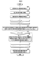
- the smoothing unit 13 smoothes the luminance image I 1 illustrated in Fig. 10(a) at STEP 3 by using the smoothing kernels of K 1 to K 5 set at STEP 2.
- the luminance image I 2 after smoothed is illustrated in Fig. 10(b) .
- the variation width of the pixel value in the luminance image I 1 before smoothing becomes narrower and a low contrast image is obtained.
- the pixel value of the image portion of the shadows B1 and B2, the repaired position B3, and the group of black dots B4 becomes approximate to that of the average luminance of the road surface, which makes it unable to be detected from the image portion in the ambient.
- the pixel value of the image portion of the white lines A1 and A2 becomes approximate to that of the average luminance of the road surface.
- the pixel value replacing unit 15 determines whether or not the variation degree ⁇ I Y (i, j) of the pixel value is equal to or smaller than a predefined value I Yth .
- the predefined value I Yth is a value (for example, equal to or smaller than zero) defined according to a possible range of the variation degree of the pixel value of the image portion of the lane mark.
- the pixel (i, j) is supposed to be the image portion of the road surface, or the image portion of the shadows B1 and B2 darker than the road surface, the repaired position B3 and the group of black dots B4. Then, the process moves to STEP 6, the pixel value replacing unit 15 replaces the pixel value P 1 (i, j) of the acquired image with the pixel value P 2 (i, j) of the smoothed image serving as an example of the specific value and moves to the next process.
- the pixel (i, j) is supposed to be the image portion of the brighter white lines A1 and A2.
- the pixel value replacing unit 15 performs the next process without replacing the pixel value of the pixel (i, j).
- a replaced image I 3 obtained after the process from STEP 4 to STEP 6 has been performed on all the pixels in the image is illustrated in Fig. 10(c) .
- the image portion of the shadows B1 and B2, the repaired position B3, and the group of black dots B4 is replaced with the pixel value of the smoothed image I 2 , and on the opposite, the image portion of the white lines A1 and A2 is maintained at the pixel value of the luminance image I 1 .
- the replaced image I 3 the image portion of the shadows B1 and B2, the repaired position B3, and the group of black dots B4 is removed with the image portion of the white lines A1 and A2 remained.
- the process moves to STEP 7 where the lane mark detecting unit 16 detects the lane mark from the replaced image I 3 .
- the replaced image I 3 the image portion of the shadows B1 and B2, the repaired position B3, and the group of black dots B4 has been removed, and only the edge points corresponding to the image portion of the white lines A1 and A2 are extracted according to the edge extraction process; therefore, the white lines A1 and A2 can be detected precisely on the basis of the edge points.
- the vehicular image process performed by the vehicular image processing device 10 of the second embodiment has been described.
- the white lines A1 and A2 on the road where the vehicle 1 is travelling can be detected precisely from the processed image.
- the predefined value I Yth is a value (for example, equal to or smaller than one) defined according to a possible range of the variation degree of the pixel values of the image portion of the lane mark.
- the smoothing kernel is set to a rectangular shape; however, as another embodiment, it is acceptable to set the smoothing kernel to a trapezoidal shape.
- the image acquiring unit 11 is configured to acquire the luminance image through the camera 2
- the smoothing unit 13 is configured to smooth the luminance image
- the pixel value replacing unit 14 is configured to replace the pixel value of the luminance image with the pixel value of the smoothed image; however, as another embodiment, for example, the image acquiring unit 11 may be configured to acquire the color image through the camera 2, to calculate the saturation of pixels according to the color components of the pixels in the color image, and to generate the saturation image with the saturation as the pixel value, and the subsequent smoothing process and the pixel value replacing process may be performed on the saturation image.
- the camera 2 is configured to photograph the front side of the vehicle 1 and the vehicular image processing device 10 is configured to detect the lane mark according to the image of the road in the front side of the vehicle 1; however, as another embodiment, it is acceptable that the camera is configured to photograph the rear side of the vehicle 1 and the vehicular image processing device 10 is configured to detect the lane mark according to the image of the rear side of the vehicle 1.
Landscapes
- Engineering & Computer Science (AREA)
- Physics & Mathematics (AREA)
- General Physics & Mathematics (AREA)
- Theoretical Computer Science (AREA)
- Multimedia (AREA)
- Geometry (AREA)
- Computer Vision & Pattern Recognition (AREA)
- Image Processing (AREA)
- Image Analysis (AREA)
Applications Claiming Priority (3)
| Application Number | Priority Date | Filing Date | Title |
|---|---|---|---|
| JP2008081332A JP4876277B2 (ja) | 2008-03-26 | 2008-03-26 | 車両用画像処理装置、車両、及び車両用画像処理プログラム |
| JP2008080728A JP4956841B2 (ja) | 2008-03-26 | 2008-03-26 | 車両用画像処理装置、車両、及び車両用画像処理プログラム |
| PCT/JP2009/001294 WO2009119070A1 (fr) | 2008-03-26 | 2009-03-24 | Dispositif de traitement d’image pour véhicule et programme de traitement d’image |
Publications (3)
| Publication Number | Publication Date |
|---|---|
| EP2256691A1 true EP2256691A1 (fr) | 2010-12-01 |
| EP2256691A4 EP2256691A4 (fr) | 2012-07-04 |
| EP2256691B1 EP2256691B1 (fr) | 2012-12-05 |
Family
ID=41113281
Family Applications (1)
| Application Number | Title | Priority Date | Filing Date |
|---|---|---|---|
| EP09723985A Active EP2256691B1 (fr) | 2008-03-26 | 2009-03-24 | Dispositif de traitement d'image pour véhicule et programme de traitement d'image |
Country Status (4)
| Country | Link |
|---|---|
| US (1) | US8681221B2 (fr) |
| EP (1) | EP2256691B1 (fr) |
| CN (1) | CN101978392B (fr) |
| WO (1) | WO2009119070A1 (fr) |
Families Citing this family (6)
| Publication number | Priority date | Publication date | Assignee | Title |
|---|---|---|---|---|
| KR101443361B1 (ko) * | 2013-04-08 | 2014-11-03 | 현대엠엔소프트 주식회사 | 네비게이션 장치의 사진지도 표시방법 및 네비게이션 장치 |
| JP5908946B2 (ja) | 2014-06-18 | 2016-04-26 | 富士重工業株式会社 | 画像処理装置 |
| JP6808586B2 (ja) * | 2017-07-05 | 2021-01-06 | クラリオン株式会社 | 車両用外界認識装置 |
| CN110809767B (zh) * | 2017-07-06 | 2022-09-09 | 华为技术有限公司 | 高级辅助驾驶系统和方法 |
| US11348344B2 (en) * | 2018-03-09 | 2022-05-31 | Pioneer Corporation | Line detection device, line detection method, program, and storage medium |
| CN113212352B (zh) | 2020-02-06 | 2023-05-05 | 佛吉亚歌乐电子有限公司 | 图像处理装置以及图像处理方法 |
Citations (1)
| Publication number | Priority date | Publication date | Assignee | Title |
|---|---|---|---|---|
| JPH06258046A (ja) * | 1993-03-05 | 1994-09-16 | Mitsubishi Electric Corp | 車線区分ライン認識装置 |
Family Cites Families (12)
| Publication number | Priority date | Publication date | Assignee | Title |
|---|---|---|---|---|
| JP3120648B2 (ja) | 1993-12-29 | 2000-12-25 | 日産自動車株式会社 | 車両用環境認識装置 |
| JP3455454B2 (ja) | 1998-12-16 | 2003-10-14 | 小糸工業株式会社 | 車両ナンバープレート認識装置 |
| US6819779B1 (en) * | 2000-11-22 | 2004-11-16 | Cognex Corporation | Lane detection system and apparatus |
| KR100391442B1 (ko) | 2000-12-27 | 2003-07-12 | 현대자동차주식회사 | 차선 이탈 방지용 영상 처리방법 |
| JP2003271930A (ja) | 2002-03-13 | 2003-09-26 | Denso Corp | レーンマーク認識装置 |
| EP1504276B1 (fr) * | 2002-05-03 | 2012-08-08 | Donnelly Corporation | Systeme de detection d'objets pour vehicule |
| CN1379359A (zh) * | 2002-05-14 | 2002-11-13 | 汤晓明 | 视频方式获取交通参数的方法 |
| JP4056971B2 (ja) * | 2003-12-25 | 2008-03-05 | 株式会社エヌ・ティ・ティ・ドコモ | 相互接続契約判定システム、相互接続契約判定装置、及び、相互接続契約判定方法 |
| US7526103B2 (en) * | 2004-04-15 | 2009-04-28 | Donnelly Corporation | Imaging system for vehicle |
| JP4348270B2 (ja) * | 2004-10-05 | 2009-10-21 | パナソニック株式会社 | Sipサーバ |
| WO2006090449A1 (fr) * | 2005-02-23 | 2006-08-31 | Fujitsu Limited | Procede, dispositif et systeme de traitement d'image et programme informatique |
| JP4603421B2 (ja) * | 2005-05-27 | 2010-12-22 | 本田技研工業株式会社 | 車両、画像処理システム、画像処理方法、及び画像処理プログラム |
-
2009
- 2009-03-24 WO PCT/JP2009/001294 patent/WO2009119070A1/fr active Application Filing
- 2009-03-24 CN CN2009801099079A patent/CN101978392B/zh active Active
- 2009-03-24 US US12/922,475 patent/US8681221B2/en active Active
- 2009-03-24 EP EP09723985A patent/EP2256691B1/fr active Active
Patent Citations (1)
| Publication number | Priority date | Publication date | Assignee | Title |
|---|---|---|---|---|
| JPH06258046A (ja) * | 1993-03-05 | 1994-09-16 | Mitsubishi Electric Corp | 車線区分ライン認識装置 |
Non-Patent Citations (3)
| Title |
|---|
| DU BUF J M H ET AL: "A quantitative comparison of edge-preserving smoothing techniques", SIGNAL PROCESSING, ELSEVIER SCIENCE PUBLISHERS B.V. AMSTERDAM, NL, vol. 21, no. 4, 1 December 1990 (1990-12-01), pages 289-301, XP026671088, ISSN: 0165-1684, DOI: 10.1016/0165-1684(90)90099-K [retrieved on 1990-12-01] * |
| PAPANANOS Y ET AL: "ANALYSIS AND VLSI ARCHITECTURE OF A NONLINEAR EDGE-PRESERVING NOISE-SMOOTHING IMAGE FILTER", IEE PROCEEDINGS G. ELECTRONIC CIRCUITS & SYSTEMS, INSTITUTION OF ELECTRICAL ENGINEERS. STEVENAGE, GB, vol. 138, no. 4, 1 August 1991 (1991-08-01), pages 433-440, XP000259462, ISSN: 0622-0039 * |
| See also references of WO2009119070A1 * |
Also Published As
| Publication number | Publication date |
|---|---|
| CN101978392A (zh) | 2011-02-16 |
| US20110019000A1 (en) | 2011-01-27 |
| EP2256691B1 (fr) | 2012-12-05 |
| EP2256691A4 (fr) | 2012-07-04 |
| US8681221B2 (en) | 2014-03-25 |
| CN101978392B (zh) | 2013-01-16 |
| WO2009119070A1 (fr) | 2009-10-01 |
Similar Documents
| Publication | Publication Date | Title |
|---|---|---|
| US8391555B2 (en) | Lane recognition apparatus for vehicle, vehicle thereof, and lane recognition program for vehicle | |
| Wu et al. | Lane-mark extraction for automobiles under complex conditions | |
| KR101392850B1 (ko) | 영상인식 기반의 차선 이탈 감지 방법 및 시스템 | |
| US8655081B2 (en) | Lane recognition system, lane recognition method, and lane recognition program | |
| US8005266B2 (en) | Vehicle surroundings monitoring apparatus | |
| US8184859B2 (en) | Road marking recognition apparatus and method | |
| CN107392139B (zh) | 一种基于霍夫变换的车道线检测方法及终端设备 | |
| EP2256691B1 (fr) | Dispositif de traitement d'image pour véhicule et programme de traitement d'image | |
| US8098933B2 (en) | Method and apparatus for partitioning an object from an image | |
| KR100816377B1 (ko) | 호프 변환을 이용한 주차구획 인식 방법, 장치 및 그를이용한 주차 보조 시스템 | |
| US20100110193A1 (en) | Lane recognition device, vehicle, lane recognition method, and lane recognition program | |
| EP1887522A1 (fr) | Dispositif de reconnaissance de vehicule et panneau routier | |
| WO2008065729A1 (fr) | Système et procédé de détection d'objet | |
| JP5402828B2 (ja) | 車線境界検出装置、車線境界検出プログラム | |
| JP2007179386A (ja) | 白線認識方法及び白線認識装置 | |
| KR101483742B1 (ko) | 지능형 차량의 차선 검출방법 | |
| JP2000113201A (ja) | 車両検出方法および装置 | |
| JPH1173514A (ja) | 車両用認識装置 | |
| JP2012252501A (ja) | 走行路認識装置及び走行路認識用プログラム | |
| JP2010061375A (ja) | 物体認識装置及びプログラム | |
| JP5091897B2 (ja) | 停止線検出装置 | |
| CN107292303B (zh) | 借助于边缘型滑动同心视窗来进行牌照检测的方法与装置 | |
| US10997743B2 (en) | Attachable matter detection apparatus | |
| EP2579229B1 (fr) | Dispositif et procédé de surveillance de l'environnement d'un véhicule | |
| JP4876277B2 (ja) | 車両用画像処理装置、車両、及び車両用画像処理プログラム |
Legal Events
| Date | Code | Title | Description |
|---|---|---|---|
| PUAI | Public reference made under article 153(3) epc to a published international application that has entered the european phase |
Free format text: ORIGINAL CODE: 0009012 |
|
| 17P | Request for examination filed |
Effective date: 20100921 |
|
| AK | Designated contracting states |
Kind code of ref document: A1 Designated state(s): AT BE BG CH CY CZ DE DK EE ES FI FR GB GR HR HU IE IS IT LI LT LU LV MC MK MT NL NO PL PT RO SE SI SK TR |
|
| AX | Request for extension of the european patent |
Extension state: AL BA RS |
|
| DAX | Request for extension of the european patent (deleted) | ||
| REG | Reference to a national code |
Ref country code: DE Ref legal event code: R079 Ref document number: 602009011715 Country of ref document: DE Free format text: PREVIOUS MAIN CLASS: G06T0007600000 Ipc: G06T0005000000 |
|
| A4 | Supplementary search report drawn up and despatched |
Effective date: 20120606 |
|
| RIC1 | Information provided on ipc code assigned before grant |
Ipc: G06T 5/00 20060101AFI20120531BHEP |
|
| GRAP | Despatch of communication of intention to grant a patent |
Free format text: ORIGINAL CODE: EPIDOSNIGR1 |
|
| RIC1 | Information provided on ipc code assigned before grant |
Ipc: G06T 5/00 20060101AFI20120614BHEP |
|
| GRAS | Grant fee paid |
Free format text: ORIGINAL CODE: EPIDOSNIGR3 |
|
| GRAA | (expected) grant |
Free format text: ORIGINAL CODE: 0009210 |
|
| AK | Designated contracting states |
Kind code of ref document: B1 Designated state(s): AT BE BG CH CY CZ DE DK EE ES FI FR GB GR HR HU IE IS IT LI LT LU LV MC MK MT NL NO PL PT RO SE SI SK TR |
|
| REG | Reference to a national code |
Ref country code: GB Ref legal event code: FG4D |
|
| REG | Reference to a national code |
Ref country code: CH Ref legal event code: EP |
|
| REG | Reference to a national code |
Ref country code: AT Ref legal event code: REF Ref document number: 587624 Country of ref document: AT Kind code of ref document: T Effective date: 20121215 |
|
| REG | Reference to a national code |
Ref country code: IE Ref legal event code: FG4D |
|
| REG | Reference to a national code |
Ref country code: DE Ref legal event code: R096 Ref document number: 602009011715 Country of ref document: DE Effective date: 20130131 |
|
| REG | Reference to a national code |
Ref country code: AT Ref legal event code: MK05 Ref document number: 587624 Country of ref document: AT Kind code of ref document: T Effective date: 20121205 |
|
| PG25 | Lapsed in a contracting state [announced via postgrant information from national office to epo] |
Ref country code: NO Free format text: LAPSE BECAUSE OF FAILURE TO SUBMIT A TRANSLATION OF THE DESCRIPTION OR TO PAY THE FEE WITHIN THE PRESCRIBED TIME-LIMIT Effective date: 20130305 Ref country code: SE Free format text: LAPSE BECAUSE OF FAILURE TO SUBMIT A TRANSLATION OF THE DESCRIPTION OR TO PAY THE FEE WITHIN THE PRESCRIBED TIME-LIMIT Effective date: 20121205 Ref country code: LT Free format text: LAPSE BECAUSE OF FAILURE TO SUBMIT A TRANSLATION OF THE DESCRIPTION OR TO PAY THE FEE WITHIN THE PRESCRIBED TIME-LIMIT Effective date: 20121205 Ref country code: FI Free format text: LAPSE BECAUSE OF FAILURE TO SUBMIT A TRANSLATION OF THE DESCRIPTION OR TO PAY THE FEE WITHIN THE PRESCRIBED TIME-LIMIT Effective date: 20121205 Ref country code: HR Free format text: LAPSE BECAUSE OF FAILURE TO SUBMIT A TRANSLATION OF THE DESCRIPTION OR TO PAY THE FEE WITHIN THE PRESCRIBED TIME-LIMIT Effective date: 20121205 Ref country code: ES Free format text: LAPSE BECAUSE OF FAILURE TO SUBMIT A TRANSLATION OF THE DESCRIPTION OR TO PAY THE FEE WITHIN THE PRESCRIBED TIME-LIMIT Effective date: 20130316 |
|
| REG | Reference to a national code |
Ref country code: NL Ref legal event code: VDEP Effective date: 20121205 |
|
| REG | Reference to a national code |
Ref country code: LT Ref legal event code: MG4D |
|
| PG25 | Lapsed in a contracting state [announced via postgrant information from national office to epo] |
Ref country code: PL Free format text: LAPSE BECAUSE OF FAILURE TO SUBMIT A TRANSLATION OF THE DESCRIPTION OR TO PAY THE FEE WITHIN THE PRESCRIBED TIME-LIMIT Effective date: 20121205 Ref country code: SI Free format text: LAPSE BECAUSE OF FAILURE TO SUBMIT A TRANSLATION OF THE DESCRIPTION OR TO PAY THE FEE WITHIN THE PRESCRIBED TIME-LIMIT Effective date: 20121205 Ref country code: GR Free format text: LAPSE BECAUSE OF FAILURE TO SUBMIT A TRANSLATION OF THE DESCRIPTION OR TO PAY THE FEE WITHIN THE PRESCRIBED TIME-LIMIT Effective date: 20130306 Ref country code: LV Free format text: LAPSE BECAUSE OF FAILURE TO SUBMIT A TRANSLATION OF THE DESCRIPTION OR TO PAY THE FEE WITHIN THE PRESCRIBED TIME-LIMIT Effective date: 20121205 |
|
| PG25 | Lapsed in a contracting state [announced via postgrant information from national office to epo] |
Ref country code: AT Free format text: LAPSE BECAUSE OF FAILURE TO SUBMIT A TRANSLATION OF THE DESCRIPTION OR TO PAY THE FEE WITHIN THE PRESCRIBED TIME-LIMIT Effective date: 20121205 |
|
| PG25 | Lapsed in a contracting state [announced via postgrant information from national office to epo] |
Ref country code: IS Free format text: LAPSE BECAUSE OF FAILURE TO SUBMIT A TRANSLATION OF THE DESCRIPTION OR TO PAY THE FEE WITHIN THE PRESCRIBED TIME-LIMIT Effective date: 20130405 Ref country code: EE Free format text: LAPSE BECAUSE OF FAILURE TO SUBMIT A TRANSLATION OF THE DESCRIPTION OR TO PAY THE FEE WITHIN THE PRESCRIBED TIME-LIMIT Effective date: 20121205 Ref country code: SK Free format text: LAPSE BECAUSE OF FAILURE TO SUBMIT A TRANSLATION OF THE DESCRIPTION OR TO PAY THE FEE WITHIN THE PRESCRIBED TIME-LIMIT Effective date: 20121205 Ref country code: BG Free format text: LAPSE BECAUSE OF FAILURE TO SUBMIT A TRANSLATION OF THE DESCRIPTION OR TO PAY THE FEE WITHIN THE PRESCRIBED TIME-LIMIT Effective date: 20130305 Ref country code: BE Free format text: LAPSE BECAUSE OF FAILURE TO SUBMIT A TRANSLATION OF THE DESCRIPTION OR TO PAY THE FEE WITHIN THE PRESCRIBED TIME-LIMIT Effective date: 20121205 Ref country code: CZ Free format text: LAPSE BECAUSE OF FAILURE TO SUBMIT A TRANSLATION OF THE DESCRIPTION OR TO PAY THE FEE WITHIN THE PRESCRIBED TIME-LIMIT Effective date: 20121205 |
|
| PG25 | Lapsed in a contracting state [announced via postgrant information from national office to epo] |
Ref country code: NL Free format text: LAPSE BECAUSE OF FAILURE TO SUBMIT A TRANSLATION OF THE DESCRIPTION OR TO PAY THE FEE WITHIN THE PRESCRIBED TIME-LIMIT Effective date: 20121205 Ref country code: PT Free format text: LAPSE BECAUSE OF FAILURE TO SUBMIT A TRANSLATION OF THE DESCRIPTION OR TO PAY THE FEE WITHIN THE PRESCRIBED TIME-LIMIT Effective date: 20130405 Ref country code: RO Free format text: LAPSE BECAUSE OF FAILURE TO SUBMIT A TRANSLATION OF THE DESCRIPTION OR TO PAY THE FEE WITHIN THE PRESCRIBED TIME-LIMIT Effective date: 20121205 |
|
| PLBE | No opposition filed within time limit |
Free format text: ORIGINAL CODE: 0009261 |
|
| STAA | Information on the status of an ep patent application or granted ep patent |
Free format text: STATUS: NO OPPOSITION FILED WITHIN TIME LIMIT |
|
| PG25 | Lapsed in a contracting state [announced via postgrant information from national office to epo] |
Ref country code: DK Free format text: LAPSE BECAUSE OF FAILURE TO SUBMIT A TRANSLATION OF THE DESCRIPTION OR TO PAY THE FEE WITHIN THE PRESCRIBED TIME-LIMIT Effective date: 20121205 Ref country code: MC Free format text: LAPSE BECAUSE OF NON-PAYMENT OF DUE FEES Effective date: 20130331 |
|
| REG | Reference to a national code |
Ref country code: CH Ref legal event code: PL |
|
| 26N | No opposition filed |
Effective date: 20130906 |
|
| PG25 | Lapsed in a contracting state [announced via postgrant information from national office to epo] |
Ref country code: CY Free format text: LAPSE BECAUSE OF FAILURE TO SUBMIT A TRANSLATION OF THE DESCRIPTION OR TO PAY THE FEE WITHIN THE PRESCRIBED TIME-LIMIT Effective date: 20121205 |
|
| PG25 | Lapsed in a contracting state [announced via postgrant information from national office to epo] |
Ref country code: IT Free format text: LAPSE BECAUSE OF FAILURE TO SUBMIT A TRANSLATION OF THE DESCRIPTION OR TO PAY THE FEE WITHIN THE PRESCRIBED TIME-LIMIT Effective date: 20121205 |
|
| REG | Reference to a national code |
Ref country code: IE Ref legal event code: MM4A |
|
| REG | Reference to a national code |
Ref country code: DE Ref legal event code: R097 Ref document number: 602009011715 Country of ref document: DE Effective date: 20130906 |
|
| PG25 | Lapsed in a contracting state [announced via postgrant information from national office to epo] |
Ref country code: CH Free format text: LAPSE BECAUSE OF NON-PAYMENT OF DUE FEES Effective date: 20130331 Ref country code: IE Free format text: LAPSE BECAUSE OF NON-PAYMENT OF DUE FEES Effective date: 20130324 Ref country code: LI Free format text: LAPSE BECAUSE OF NON-PAYMENT OF DUE FEES Effective date: 20130331 |
|
| PGFP | Annual fee paid to national office [announced via postgrant information from national office to epo] |
Ref country code: FR Payment date: 20140311 Year of fee payment: 6 |
|
| PG25 | Lapsed in a contracting state [announced via postgrant information from national office to epo] |
Ref country code: MT Free format text: LAPSE BECAUSE OF FAILURE TO SUBMIT A TRANSLATION OF THE DESCRIPTION OR TO PAY THE FEE WITHIN THE PRESCRIBED TIME-LIMIT Effective date: 20121205 |
|
| PGFP | Annual fee paid to national office [announced via postgrant information from national office to epo] |
Ref country code: GB Payment date: 20150318 Year of fee payment: 7 |
|
| PG25 | Lapsed in a contracting state [announced via postgrant information from national office to epo] |
Ref country code: TR Free format text: LAPSE BECAUSE OF FAILURE TO SUBMIT A TRANSLATION OF THE DESCRIPTION OR TO PAY THE FEE WITHIN THE PRESCRIBED TIME-LIMIT Effective date: 20121205 |
|
| PG25 | Lapsed in a contracting state [announced via postgrant information from national office to epo] |
Ref country code: LU Free format text: LAPSE BECAUSE OF NON-PAYMENT OF DUE FEES Effective date: 20130324 Ref country code: HU Free format text: LAPSE BECAUSE OF FAILURE TO SUBMIT A TRANSLATION OF THE DESCRIPTION OR TO PAY THE FEE WITHIN THE PRESCRIBED TIME-LIMIT; INVALID AB INITIO Effective date: 20090324 Ref country code: MK Free format text: LAPSE BECAUSE OF FAILURE TO SUBMIT A TRANSLATION OF THE DESCRIPTION OR TO PAY THE FEE WITHIN THE PRESCRIBED TIME-LIMIT Effective date: 20121205 |
|
| REG | Reference to a national code |
Ref country code: FR Ref legal event code: ST Effective date: 20151130 |
|
| PG25 | Lapsed in a contracting state [announced via postgrant information from national office to epo] |
Ref country code: FR Free format text: LAPSE BECAUSE OF NON-PAYMENT OF DUE FEES Effective date: 20150331 |
|
| GBPC | Gb: european patent ceased through non-payment of renewal fee |
Effective date: 20160324 |
|
| PG25 | Lapsed in a contracting state [announced via postgrant information from national office to epo] |
Ref country code: GB Free format text: LAPSE BECAUSE OF NON-PAYMENT OF DUE FEES Effective date: 20160324 |
|
| REG | Reference to a national code |
Ref country code: DE Ref legal event code: R084 Ref document number: 602009011715 Country of ref document: DE |
|
| PGFP | Annual fee paid to national office [announced via postgrant information from national office to epo] |
Ref country code: DE Payment date: 20230125 Year of fee payment: 15 |