EP2256570A1 - Verfahren und Steuereinheit zum Betreiben eines flüchtigen Speichers, Schaltungsanordnung und Fahrtenschreiber - Google Patents
Verfahren und Steuereinheit zum Betreiben eines flüchtigen Speichers, Schaltungsanordnung und Fahrtenschreiber Download PDFInfo
- Publication number
- EP2256570A1 EP2256570A1 EP10159493A EP10159493A EP2256570A1 EP 2256570 A1 EP2256570 A1 EP 2256570A1 EP 10159493 A EP10159493 A EP 10159493A EP 10159493 A EP10159493 A EP 10159493A EP 2256570 A1 EP2256570 A1 EP 2256570A1
- Authority
- EP
- European Patent Office
- Prior art keywords
- supply signal
- volatile memory
- vmem
- switching element
- signal
- Prior art date
- Legal status (The legal status is an assumption and is not a legal conclusion. Google has not performed a legal analysis and makes no representation as to the accuracy of the status listed.)
- Granted
Links
Images

Classifications
-
- G—PHYSICS
- G06—COMPUTING OR CALCULATING; COUNTING
- G06F—ELECTRIC DIGITAL DATA PROCESSING
- G06F1/00—Details not covered by groups G06F3/00 - G06F13/00 and G06F21/00
- G06F1/26—Power supply means, e.g. regulation thereof
- G06F1/30—Means for acting in the event of power-supply failure or interruption, e.g. power-supply fluctuations
-
- G—PHYSICS
- G06—COMPUTING OR CALCULATING; COUNTING
- G06F—ELECTRIC DIGITAL DATA PROCESSING
- G06F11/00—Error detection; Error correction; Monitoring
- G06F11/07—Responding to the occurrence of a fault, e.g. fault tolerance
- G06F11/16—Error detection or correction of the data by redundancy in hardware
- G06F11/20—Error detection or correction of the data by redundancy in hardware using active fault-masking, e.g. by switching out faulty elements or by switching in spare elements
- G06F11/2015—Redundant power supplies
Definitions
- the invention relates to a method and a control unit for operating a volatile memory.
- a digital tachograph which is also referred to as a digital tachograph stores for a given period, for example on a driver-bound smart card all eligible events that are related to the driving. So z. As steering, work, standby, rest, interruption times. The entire data can be read out digitally by the control authorities or the holder of the vehicle in accordance with prescribed legal regulations. The storage of this data has high demands.
- JP 2001142508 A discloses a circuit arrangement with a RAM memory which is separable from its supply by means of a switching element.
- US 2006/0133135 A1 discloses an array of SRAM cells driven by control electronics.
- a voltage for supplying the SRAM cells is higher than a voltage for supplying the control electronics.
- the invention is characterized according to a first and second aspect by a method and a corresponding control unit for operating a volatile memory to which a supply signal can be supplied.
- the supply signal is formed either as a first supply signal of a first supply signal source or as a second supply signal of a second supply signal source. When available first supply signal this and otherwise the second supply signal is used as a supply signal.
- the supply signal is fed to the volatile memory depending on a switching position of a switching element. An interruption of the first supply signal is detected. During the detected interrupted first supply signal, the switching position of the switching element for a predetermined period of time is set such that the volatile memory, the supply signal is supplied.
- the switching position of the switching element is set such that the volatile memory is electrically decoupled from the supply signal.
- the respective supply signal is formed for example as a respective supply voltage.
- the switching position of the switching element remains unchanged before the detection of the interrupted first supply signal and during the present interrupted supply signal for supplying the volatile memory, so that in the volatile memory, such.
- stored data remain stored.
- the volatile memory has the advantage that frequently occurring or changing data can be stored quickly and without limitation of the write cycles in this.
- a non-volatile memory typically only a limited number of write cycles.
- the second supply signal source is preferably designed as a rechargeable energy storage.
- a temperature is determined which is representative of a temperature at the volatile memory.
- the duration is specified depending on the determined temperature.
- a current consumption of the volatile memory is dependent on the temperature of the memory, so that the predetermined period of time can be suitably adapted to the current consumption and thus a reliable operation of the volatile memory can be ensured.
- the volatile memory is coupled to a non-volatile memory.
- the time duration is specified. This enables a reliable backup of at least one predetermined selection of data stored in the volatile memory.
- the available first supply signal is detected.
- the expiration of the predetermined period of time is ignored and the switching position of the switching element is predetermined such that the volatile memory, the supply signal is supplied, if the detection of the available first supply signal during the predetermined period of time.
- the invention is characterized according to a third aspect by a circuit arrangement with the volatile memory and a supply signal unit, the input side, the first and the second supply signal and the output side, the supply signal is assigned.
- the supply signal unit is designed to predetermine this as the supply signal when the first supply signal is available, and otherwise the second supply signal on the output side.
- the circuit arrangement further comprises the switching element, to which the supply signal is assigned at its first terminal and which is electrically coupled with its second terminal to the volatile memory. Furthermore, the circuit arrangement has a control unit according to the second aspect.
- control unit is electrically coupled to the supply signal unit for supplying the supply signal, independently of the switching position of the switching element. This allows a reliable operation of the control unit when available or during the interrupted first supply signal.
- the invention is characterized according to a fourth aspect by a tachograph in a motor vehicle.
- the tachograph comprises a circuit arrangement according to the third aspect.
- the first supply signal is designed as a vehicle electrical system voltage signal of the motor vehicle. This allows reliable and safe operation of the tachograph.
- the interrupted first supply signal is present, for example, when an ignition of the motor vehicle is switched off or there is an interruption of the vehicle electrical system voltage signal resulting from an accident.
- control unit is designed, depending on a further predetermined control signal, the accident situation of Motor vehicle represents to ignore the expiration of the predetermined period of time and the switching position is supplied to a volatile memory, the supply signal, if the first supply signal is interrupted. If an accident is registered, due to the permanent supply of the volatile memory by means of the second supply signal source, all accident data can be stored and recorded. The data remain stored in the volatile memory until the supply signal source is discharged or they have been transferred to the non-volatile memory without errors.
- a tachograph TG ( FIG. 1 ) comprises a circuit arrangement with a supply signal unit U, a volatile memory VMEM, a first and second control unit CTRL1, CTRL2, a switching element SW and a second supply signal source.
- the tachograph TG is preferably arranged in a motor vehicle and in this with a first supply signal source, such. B. the battery of the motor vehicle, electrically coupled.
- the second supply signal source is designed, for example, as a rechargeable energy store.
- the first and second supply signal source provide a first and second supply signal V1, V2 available.
- the first and second supply signals are assigned to the supply signal unit U on the input side.
- the supply signal unit U comprises a first and second diode D1, D2, which are electrically coupled to the first and second supply signal source such that a supply signal V_M is available on the output side at a common connection point TP of the first and second diode D1, D2.
- the supply signal unit U is designed to predetermine the output signal V1 and otherwise the second supply signal V2 as the supply signal V_M when the first supply signal V1 is available.
- the common connection point TP is electrically coupled to the first control unit CTRL1 for its supply.
- a first terminal of the switching element SW is electrically connected to the common connection point TP and a second terminal of the switching element SW is electrically coupled to the volatile memory VMEM to supply the supply voltage V_M to the volatile memory VMEM when the switching element SW is switched on.
- the second control unit CTRL2 comprises a non-volatile memory NVMEM, such. B. a flash or FRAM memory, which is electrically coupled to the volatile memory VMEM to transfer stored data between the volatile and non-volatile memory VMEM, NVMEM.
- the first and second control units CTRL1, CTRL2 are electrically coupled to each other via a control signal line, via which a control signal S from the second to the first control unit CTRL2, CTRL1 is transferable.
- the control signal S is representative of an error-free data transfer of data from the volatile memory VMEM into the nonvolatile memory NVMEM.
- a further control signal is transmitted by means of the control signal line, which is representative of a detected accident situation of the motor vehicle. The detection of the accident situation takes place, for example, by means of the second control unit CTRL2.
- the first control unit CTRL1 is designed to determine a temperature at the volatile memory VMEM by means of a temperature sensor TEMP.
- a current consumption of the volatile memory VMEM is typically dependent on a temperature at the volatile memory VMEM.
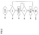
- the first control unit CTRL1 is preferably designed to provide a method for operating the volatile memory VMEM (FIG. FIG. 2 ).
- the first control unit CTRL1 may also be referred to as a control unit for operating the volatile memory VMEM.
- the method is started in a step S0.
- the switching element SW is turned on here, such. B. when starting the motor vehicle.
- a step S2 it is detected whether the first supply signal V1 is applied or interrupted.
- the method is ended in a step S10 or alternatively executed again in step S2.
- the switching position of the switching element SW is predetermined such that the volatile memory VMEM is acted upon by the second diode D2 with the second supply signal V2.
- the temperature at the volatile memory VMEM is determined in this step.
- a time period T is determined during which the switching position of the switching element SW is still switched on.
- the duration T may be fixed and / or variably adjustable, such. B. 3 to 60 min, and / or be predetermined depending on the determined temperature. Alternatively or additionally, the time duration T is predetermined as a function of the control signal S. In a step S6 it is checked whether the predetermined time period T has expired. Alternatively or additionally, depending on a detected accident, which is signaled by means of the further control signal, the course of the time period T is ignored and the switching position of the switching element SW predetermined such that the volatile memory VMEM the supply signal V_M continues to be supplied, even if the first supply signal V1 is interrupted. During the predetermined period of time T, the first supply signal V1 is constantly monitored in step S6.
- step S10 If the first supply signal V1 is again present, the method is ended in step S10. If the predetermined time period T has expired, and the first supply signal V1 is still interrupted, the switching position of the switching element SW is predetermined in a step S8 such that it is electrically decoupled from volatile memory VMEM of the supply signal V_M. In step S10, the method is ended or, alternatively, processed again in step S2.
Landscapes
- Engineering & Computer Science (AREA)
- Theoretical Computer Science (AREA)
- Physics & Mathematics (AREA)
- General Engineering & Computer Science (AREA)
- General Physics & Mathematics (AREA)
- Quality & Reliability (AREA)
- Techniques For Improving Reliability Of Storages (AREA)
Abstract
Description
- Die Erfindung betrifft ein Verfahren und eine Steuereinheit zum Betreiben eines flüchtigen Speichers.
- Ein digitaler Fahrtenschreiber, der auch als digitaler Tachograph bezeichnet wird, speichert für einen vorgegebenen Zeitraum beispielsweise auf einer fahrergebundenen Chipkarte alle in Frage kommenden Ereignisse, die mit dem Fahrbetrieb in Beziehung stehen. So werden z. B. Lenk-, Arbeits-, Bereitschafts-, Ruhe-, Unterbrechungszeiten gespeichert. Die gesamten Daten können von Kontrollbehörden oder dem Halter des Fahrzeugs entsprechend vorgegebener gesetzlicher Vorschriften digital ausgelesen werden. An die Speicherung dieser Daten werden hohe Anforderungen gestellt.
-
JP 2001142508 A -
US 2006/0133135 A1 offenbart ein Feld von SRAM-Zellen, das mit einer Steuerelektronik angesteuert wird. Dabei ist eine Spannung zur Versorgung der SRAM-Zellen höher als eine Spannung zur Versorgung der Steuerelektronik. - Es ist Aufgabe der Erfindung, ein Verfahren, eine Steuereinheit, eine Schaltungsanordnung und einen Fahrtenschreiber zu schaffen, der eine besonders zuverlässige und zugleich stromreduzierte Datenspeicherung ermöglicht.
- Die Erfindung zeichnet sich gemäß einem ersten und zweiten Aspekt aus durch ein Verfahren und eine korrespondierende Steuereinheit zum Betreiben eines flüchtigen Speichers, dem ein Versorgungssignal zuführbar ist. Das Versorgungssignal ist entweder als ein erstes Versorgungssignal einer ersten Versorgungssignalquelle oder als ein zweites Versorgungssignal einer zweiten Versorgungssignalquelle ausgebildet. Bei zur Verfügung stehendem erstem Versorgungssignal wird dieses und ansonsten das zweite Versorgungssignal als Versorgungssignal eingesetzt. Das Versorgungssignal ist abhängig von einer Schaltstellung eines Schaltelementes dem flüchtigen Speicher zuführbar. Eine Unterbrechung des ersten Versorgungssignals wird detektiert. Während des detektierten unterbrochenen ersten Versorgungssignals wird die Schaltstellung des Schaltelementes für eine vorgegebene Zeitdauer derart vorgegeben, dass dem flüchtigen Speicher das Versorgungssignal zugeführt ist. Ferner wird während des detektierten unterbrochenen ersten Versorgungssignals nach Ablauf der vorgegebenen Zeitdauer die Schaltstellung des Schaltelementes derart vorgegeben, dass der flüchtige Speicher von dem Versorgungssignal elektrisch entkoppelt ist. Dies hat den Vorteil, dass zumindest eine vorgegebene Auswahl von in dem flüchtigen Speicher gespeicherten Daten vor der elektrischen Entkopplung von dem Versorgungssignal gesichert werden kann. So können notwendige Daten, so z. B. Unfalldaten, welche mit hoher Frequenz oder kurz vor einer Unterbrechung anfallen, zuverlässig gespeichert werden. Ferner erhöht dies die Lebensdauer der zweiten Versorgungssignalquelle und kann somit dazu beitragen, einen Austausch der zweiten Versorgungssignalquelle zu vermeiden.
- Das jeweilige Versorgungssignal ist beispielsweise als jeweilige Versorgungsspannung ausgebildet. Vorzugsweise bleibt die Schaltstellung des Schaltelementes vor der Detektion des unterbrochenen ersten Versorgungssignals und während dem vorliegenden unterbrochenen Versorgungssignal zur Versorgung des flüchtigen Speichers unverändert, so dass die in dem flüchtigen Speicher, so z. B. einem SRAM-Speicher, gespeicherten Daten gespeichert bleiben. Der flüchtige Speicher hat den Vorteil, dass häufig anfallende oder sich ändernde Daten schnell und ohne Begrenzung der Schreibzyklen in diesem gespeichert werden können. Ein nichtflüchtiger Speicher weist typischerweise nur eine begrenzte Anzahl an Schreibzyklen auf. Die zweite Versorgungssignalquelle ist vorzugsweise als wiederaufladbarer Energiespeicher ausgebildet.
- In einer vorteilhaften Ausgestaltung des ersten und zweiten Aspekts wird eine Temperatur ermittelt, die repräsentativ ist für eine Temperatur am flüchtigen Speicher. Die Zeitdauer wird abhängig von der ermittelten Temperatur vorgegeben. Vorzugsweise ist eine Stromaufnahme des flüchtigen Speichers abhängig von der Temperatur des Speichers, so dass die vorgegebene Zeitdauer geeignet an die Stromaufnahme angepasst und somit ein zuverlässiger Betrieb des flüchtigen Speichers gewährleistet werden kann.
- In einer weiteren vorteilhaften Ausgestaltung des ersten und zweiten Aspekts ist der flüchtige Speicher mit einem nichtflüchtigen Speicher gekoppelt. Abhängig von einem vorgegebenen Steuersignal, das repräsentativ ist für einen fehlerfreien Datentransfer von Daten von dem flüchtigen Speicher in den nichtflüchtigen Speicher, wird die Zeitdauer vorgegeben. Dies ermöglicht eine zuverlässige Sicherung zumindest einer vorgegebenen Auswahl von Daten, die in dem flüchtigen Speicher gespeichert sind.
- In einer weiteren vorteilhaften Ausgestaltung des ersten und zweiten Aspekts wird das zur Verfügung stehende erste Versorgungssignal detektiert. Der Ablauf der vorgegebenen Zeitdauer wird ignoriert und die Schaltstellung des Schaltelementes derart vorgegeben, dass dem flüchtigen Speicher das Versorgungssignal zugeführt ist, falls die Detektion des zur Verfügung stehenden ersten Versorgungssignals während der vorgegebenen Zeitdauer erfolgt. Dies ermöglicht bei Unterbrechungen des ersten Versorgungssignals, die kürzer sind als die vorgegebene Zeitdauer, dass Daten in dem flüchtigen Speicher weiterhin vorliegen und somit beispielsweise Startup-Vorgänge, in denen Daten erneut in den flüchtigen Speicher kopiert werden müssen, entfallen können.
- Die Erfindung zeichnet sich gemäß einem dritten Aspekt aus durch eine Schaltungsanordnung mit dem flüchtigen Speicher und einer Versorgungssignaleinheit, der eingangsseitig das erste und das zweite Versorgungssignal und ausgangsseitig das Versorgungssignal zugeordnet ist. Die Versorgungssignaleinheit ist ausgebildet, bei zur Verfügung stehendem erstem Versorgungssignal dieses und ansonsten das zweite Versorgungssignal ausgangsseitig als Versorgungssignal vorzugeben. Die Schaltungsanordnung umfasst ferner das Schaltelement, dem an seinem ersten Anschluss das Versorgungssignal zugeordnet ist und das mit seinem zweiten Anschluss mit dem flüchtigen Speicher elektrisch gekoppelt ist. Des Weiteren weist die Schaltungsanordnung eine Steuereinheit gemäß dem zweiten Aspekt auf.
- In einer vorteilhaften Ausgestaltung des dritten Aspekts ist die Steuereinheit mit der Versorgungssignaleinheit zum Zuführen des Versorgungssignals unabhängig von der Schaltstellung des Schaltelements elektrisch gekoppelt. Dies ermöglicht bei zur Verfügung stehendem oder während des unterbrochenen ersten Versorgungssignals einen zuverlässigen Betrieb der Steuereinheit.
- Die Erfindung zeichnet sich gemäß einem vierten Aspekt aus durch einen Fahrtenschreiber in einem Kraftfahrzeug. Der Fahrtenschreiber umfasst eine Schaltungsanordnung gemäß dem dritten Aspekt. Das erste Versorgungssignal ist dabei als Bordnetzspannungssignal des Kraftfahrzeugs ausgebildet. Dies ermöglicht einen zuverlässigen und sicheren Betrieb des Fahrtenschreibers. Das unterbrochene erste Versorgungssignal liegt beispielsweise vor, wenn eine Zündung des Kraftfahrzeugs ausgeschaltet ist oder eine aus einem Unfall resultierende Unterbrechung des Bordnetzspannungssignals vorliegt.
- In einer vorteilhaften Ausgestaltung des vierten Aspekts ist die Steuereinheit ausgebildet, abhängig von einem weiteren vorgegebenen Steuersignal, das eine Unfallsituation des Kraftfahrzeugs repräsentiert, den Ablauf der vorgegebenen Zeitdauer zu ignorieren und die Schaltstellung einen flüchtigen Speicher das Versorgungssignal zugeführt ist, falls das erste Versorgungssignal unterbrochen ist. Wird ein Unfall registriert, können aufgrund der dauerhaften Versorgung des flüchtigen Speichers mittels der zweiten Versorgungssignalquelle alle Unfalldaten gespeichert und aufgezeichnet werden. Dabei bleiben die Daten solange in dem flüchtigen Speicher gespeichert, bis die Versorgungssignalquelle entladen ist oder diese fehlerfrei in den nichtflüchtigen Speicher übertragen wurden.
- Ausführungsbeispiele der Erfindung sind im Folgenden anhand der schematischen Zeichnungen näher erläutert. Es zeigen:
- Figur 1
- Fahrtenschreiber,
- Figur 2
- Ablaufdiagramm.
- Elemente gleicher Konstruktion oder Funktion sind figuren-übergreifend mit den gleichen Bezugszeichen versehen.
- Ein Fahrtenschreiber TG (
Figur 1 ) umfasst eine Schaltungsanordnung mit einer Versorgungssignaleinheit U, einem flüchtigen Speicher VMEM, einer ersten und zweiten Steuereinheit CTRL1, CTRL2, einem Schaltelement SW und einer zweiten Versorgungssignalquelle. Der Fahrtenschreiber TG ist vorzugsweise in einem Kraftfahrzeug angeordnet und in diesem mit einer ersten Versorgungssignalquelle, so z. B. der Batterie des Kraftfahrzeugs, elektrisch gekoppelt. Die zweite Versorgungssignalquelle ist beispielsweise als wiederaufladbarer Energiespeicher ausgebildet. Die erste bzw. zweite Versorgungssignalquelle stellen ein erstes bzw. zweites Versorgungssignal V1, V2 zur Verfügung. - Das erste und zweite Versorgungssignal sind der Versorgungssignaleinheit U eingangsseitig zugeordnet. Die Versorgungssignaleinheit U umfasst eine erste und zweite Diode D1, D2, die derart mit der ersten und zweiten Versorgungssignalquelle elektrisch gekoppelt sind, dass an einem gemeinsamen Anschlusspunkt TP der ersten und zweiten Diode D1, D2 ein Versorgungssignal V_M ausgangsseitig zur Verfügung steht. Die Versorgungssignaleinheit U ist ausgebildet, bei zur Verfügung stehendem ersten Versorgungssignal V1 dieses und ansonsten das zweite Versorgungssignal V2 als Versorgungssignal V_M ausgangsseitig vorzugeben.
- Der gemeinsame Anschlusspunkt TP ist mit der ersten Steuereinheit CTRL1 zu dessen Versorgung elektrisch gekoppelt. Ein erster Anschluss des Schaltelementes SW ist mit dem gemeinsame Anschlusspunkt TP und ein zweiter Anschluss des Schaltelements SW ist mit dem flüchtigen Speicher VMEM elektrisch gekoppelt, um bei eingeschalteter Schaltstellung des Schaltelementes SW dem flüchtigen Speicher VMEM das Versorgungssignal V_M zu zuführen.
- Die zweite Steuereinheit CTRL2 umfasst einen nichtflüchtigen Speicher NVMEM, so z. B. einen Flash- oder FRAM-Speicher, der mit dem flüchtigen Speicher VMEM elektrisch gekoppelt ist, um gespeicherte Daten zwischen dem flüchtigen und nichtflüchtigen Speicher VMEM, NVMEM zu übertragen. Die erste und zweite Steuereinheit CTRL1, CTRL2 sind über eine Steuersignalleitung elektrisch miteinander gekoppelt, über die ein Steuersignal S von der zweiten zu der ersten Steuereinheit CTRL2, CTRL1 übertragbar ist. Das Steuersignal S ist repräsentativ für einen fehlerfreien Datentransfer von Daten von dem flüchtigen Speicher VMEM in den nichtflüchtigen Speicher NVMEM. Alternativ oder zusätzlich wird mittels der Steuersignalleitung ein weiteres Steuersignal übertragen, das repräsentativ ist für eine detektierte Unfallsituation des Kraftfahrzeugs. Die Detektion der Unfallsituation erfolgt beispielsweise mittels der zweiten Steuereinheit CTRL2.
- Die erste Steuereinheit CTRL1 ist ausgebildet, mittels eines Temperatursensors TEMP eine Temperatur am flüchtigen Speicher VMEM zu ermitteln. Eine Stromaufnahme des flüchtigen Speichers VMEM ist typischerweise abhängig von einer Temperatur am flüchtigen Speicher VMEM.
- Die erste Steuereinheit CTRL1 ist vorzugsweise ausgebildet, ein Verfahren zum Betreiben des flüchtigen Speichers VMEM (
Figur 2 ) abzuarbeiten. Alternativ kann die erste Steuereinheit CTRL1 auch als Steuereinheit zum Betreiben des flüchtigen Speichers VMEM bezeichnet werden. - Das Verfahren wird in einem Schritt S0 gestartet. Vorzugsweise wird hier das Schaltelement SW eingeschaltet, so z. B. beim Starten des Kraftfahrzeugs. In einem Schritt S2 wird detektiert, ob das erste Versorgungssignal V1 anliegt oder unterbrochen ist. Bei einem anliegenden ersten Versorgungssignal V1 wird das Verfahren in einem Schritt S10 beendet oder alternativ im Schritt S2 erneut ausgeführt. Bei einem unterbrochenen ersten Versorgungssignal V1 wird die Schaltstellung des Schaltelementes SW derart vorgegeben, dass der flüchtige Speicher VMEM mittels der zweiten Diode D2 mit dem zweiten Versorgungssignal V2 beaufschlagt wird. Zusätzlich wird in diesem Schritt die Temperatur am flüchtigen Speicher VMEM ermittelt. In einem Schritt S4 wird eine Zeitdauer T ermittelt, während dessen die Schaltstellung des Schaltelementes SW weiterhin eingeschaltet ist. Die Zeitdauer T kann fest vorgegeben und/oder variabel einstellbar, so z. B. 3 bis 60 min, und/oder abhängig von der ermittelten Temperatur vorgegeben sein. Alternativ oder zusätzlich wird die Zeitdauer T abhängig von dem Steuersignal S vorgegeben. In einem Schritt S6 wird überprüft, ob die vorgegebene Zeitdauer T abgelaufen ist. Alternativ oder zusätzlich wird abhängig von einem detektierten Unfall, der mittels des weiteren Steuersignals signalisiert wird, der Ablauf der Zeitdauer T ignoriert und die Schaltstellung des Schaltelementes SW derart vorgegeben, dass dem flüchtigen Speicher VMEM das Versorgungssignal V_M weiterhin zugeführt ist, auch wenn das erste Versorgungssignal V1 unterbrochen ist. Während der vorgegebenen Zeitdauer T wird in dem Schritt S6 das erste Versorgungssignal V1 ständig überwacht. Liegt das erste Versorgungssignal V1 erneut an, wird das Verfahren in dem Schritt S10 beendet. Ist die vorgegebene Zeitdauer T abgelaufen, und das erste Versorgungssignal V1 ist weiterhin unterbrochen, wird in einem Schritt S8 die Schaltstellung des Schaltelement SW derart vorgegeben, dass er flüchtige Speicher VMEM von dem Versorgungssignal V_M elektrisch entkoppelt ist. In dem Schritt S10 wird das Verfahren beendet oder alternativ in dem Schritt S2 erneut abgearbeitet.
Claims (9)
- Verfahren zum Betreiben eines flüchtigen Speichers (VMEM), dem ein Versorgungssignal (V_M) zuführbar ist, wobei das Versorgungssignal (V_M) entweder als ein erstes Versorgungssignal (V1) einer ersten Versorgungssignalquelle oder als ein zweites Versorgungssignal (V2) einer zweiten Versorgungssignalquelle ausgebildet ist, wobei bei zur Verfügung stehendem ersten Versorgungssignal (V1) dieses als Versorgungssignal (V_M) und ansonsten das zweite Versorgungssignal (V2) als Versorgungssignal (V_M) eingesetzt wird, wobei das Versorgungssignal (V_M) abhängig von einer Schaltstellung eines Schaltelementes (SW) dem flüchtigen Speicher (VMEM) zuführbar ist, bei dem- eine Unterbrechung des ersten Versorgungssignals (V1) detektiert wird,- während des detektierten unterbrochenen ersten Versorgungssignals (V1):-- die Schaltstellung des Schaltelementes (SW) für eine vorgegebene Zeitdauer (T) derart vorgegeben wird, dass dem flüchtigen Speicher (VMEM) das Versorgungssignal (V_M) zugeführt ist,-- nach Ablauf der vorgegebenen Zeitdauer (T) die Schaltstellung des Schaltelementes (SW) derart vorgegeben wird, dass der flüchtige Speicher (VMEM) von dem Versorgungssignal (V_M) elektrisch entkoppelt ist.
- Verfahren nach Anspruch 1, bei dem- eine Temperatur ermittelt wird, die repräsentativ ist für eine Temperatur am flüchtigen Speicher (VMEM),- die Zeitdauer (T) abhängig von der ermittelten Temperatur (TEMP) vorgegeben wird.
- Verfahren nach Anspruch 1 oder 2, bei dem der flüchtige Speicher (VMEM) mit einem nichtflüchtigen Speicher (NVMEM) gekoppelt ist und abhängig von einem vorgegebenen Steuersignal (S), das repräsentativ ist für einen fehlerfreien Datentransfer von Daten von dem flüchtigen Speicher (VMEM) in den nichtflüchtigen Speicher (NVMEM), die Zeitdauer (T) vorgegeben wird.
- Verfahren nach einem der vorstehenden Ansprüche, bei dem- das zur Verfügung stehende erste Versorgungssignal (V1) detektiert wird,- der Ablauf der vorgegebenen Zeitdauer (T) ignoriert wird und die Schaltstellung des Schaltelementes (SW) derart vorgegeben wird, dass dem flüchtigen Speicher (VMEM) das Versorgungssignal (V_M) zugeführt ist, falls die Detektion des zur Verfügung stehenden ersten Versorgungssignals (V1) während der vorgegebenen Zeitdauer (T) erfolgt.
- Steuereinheit (CTRL1) zum Betreiben eines flüchtigen Speichers (VMEM), dem ein Versorgungssignal (V_M) zuführbar ist, wobei das Versorgungssignal (V_M) entweder als ein erstes Versorgungssignal (V1) einer ersten Versorgungssignalquelle oder als ein zweites Versorgungssignal (V2) einer zweiten Versorgungssignalquelle ausgebildet ist, wobei bei zur Verfügung stehendem ersten Versorgungssignal (V1) dieses als Versorgungssignal (V_M) und ansonsten das zweite Versorgungssignal (V2) als Versorgungssignal (V_M) eingesetzt wird, wobei das Versorgungssignal (V_M) abhängig von einer Schaltstellung eines Schaltelementes (SW) dem flüchtigen Speicher (VMEM) zuführbar ist, wobei die Steuereinheit (CTRL1) ausgebildet ist,- eine Unterbrechung des ersten Versorgungssignals (V1) zu detektieren,- während des detektierten unterbrochenen ersten Versorgungssignals (V1) :-- die Schaltstellung des Schaltelementes (SW) für eine vorgegebene Zeitdauer (T) derart vorzugeben, dass dem flüchtigen Speicher (VMEM) das Versorgungssignal (V_M) zugeführt ist,-- nach Ablauf der vorgegebenen Zeitdauer (T) die Schaltstellung des Schaltelementes (SW) derart vorzugeben, dass der flüchtige Speicher (VMEM) von dem Versorgungssignal (V_M) elektrisch entkoppelt ist.
- Schaltungsanordnung umfassend- den flüchtigen Speicher (VMEM),- eine Versorgungssignaleinheit (U), der eingangsseitig das erste und das zweite Versorgungssignal (V1, V2) und ausgangsseitig das Versorgungssignal (V_M) zugeordnet ist, wobei die Versorgungssignaleinheit (U) ausgebildet ist, bei zur Verfügung stehendem ersten Versorgungssignal (V1) dieses ausgangsseitig als Versorgungssignal (V_M) und ansonsten das zweite Versorgungssignal (V2) ausgangsseitig als Versorgungssignal (V_M) vorzugeben,- das Schaltelement (SW), dem an seinem ersten Anschluss das Versorgungssignal (V_M) zugeordnet ist und das mit seinem zweiten Anschluss mit dem flüchtigen Speicher (VMEM) elektrisch gekoppelt ist,- eine Steuereinheit (CTRL1) gemäß Patentanspruch 5.
- Schaltungsanordnung nach Anspruch 6, bei der die Steuereinheit (CTRL1) mit der Versorgungssignaleinheit (U) zum Zuführen des Versorgungssignals (V_M) unabhängig von der Schaltstellung des Schaltelements (SW) elektrisch gekoppelt ist.
- Fahrtenschreiber (TG) in einem Kraftfahrzeug, wobei der Fahrtenschreiber (TG) eine Schaltungsanordnung gemäß der Ansprüche 6 oder 7 umfasst, wobei das erste Versorgungssignal (V1) als Bordnetzspannungssignal des Kraftfahrzeugs ausgebildet ist.
- Fahrtenschreiber (TG) nach Anspruch 8, bei der die Steuereinheit (CTRL1) ausgebildet ist, abhängig von einem weiteren vorgegebenen Steuersignal, das eine Unfallsituation des Kraftfahrzeugs repräsentiert, den Ablauf der vorgegebenen Zeitdauer (T) zu ignorieren und die Schaltstellung des Schaltelementes (SW) derart vorzugeben, dass dem flüchtigen Speicher (VMEM) das Versorgungssignal (V_M) zugeführt ist, falls das erste Versorgungssignal (V1) unterbrochen ist.
Applications Claiming Priority (1)
| Application Number | Priority Date | Filing Date | Title |
|---|---|---|---|
| DE102009020731A DE102009020731A1 (de) | 2009-05-11 | 2009-05-11 | Verfahren und Steuereinheit zum Betreiben eines flüchtigen Speichers, Schaltungsanordnung und Fahrtenschreiber |
Publications (2)
| Publication Number | Publication Date |
|---|---|
| EP2256570A1 true EP2256570A1 (de) | 2010-12-01 |
| EP2256570B1 EP2256570B1 (de) | 2016-12-07 |
Family
ID=42315634
Family Applications (1)
| Application Number | Title | Priority Date | Filing Date |
|---|---|---|---|
| EP10159493.5A Not-in-force EP2256570B1 (de) | 2009-05-11 | 2010-04-09 | Verfahren und Steuereinheit zum Betreiben eines flüchtigen Speichers, Schaltungsanordnung und Fahrtenschreiber |
Country Status (3)
| Country | Link |
|---|---|
| US (1) | US8305830B2 (de) |
| EP (1) | EP2256570B1 (de) |
| DE (1) | DE102009020731A1 (de) |
Families Citing this family (1)
| Publication number | Priority date | Publication date | Assignee | Title |
|---|---|---|---|---|
| DE102015106189B4 (de) * | 2015-04-22 | 2019-07-18 | Audi Ag | Schalten eines Bordnetzes eines Kraftfahrzeugs |
Citations (7)
| Publication number | Priority date | Publication date | Assignee | Title |
|---|---|---|---|---|
| EP0385516A2 (de) * | 1983-06-06 | 1990-09-05 | Hitachi, Ltd. | Speicher |
| JP2001142508A (ja) | 1999-11-12 | 2001-05-25 | Fuji Electric Co Ltd | プログラマブルコントローラ |
| US20020116651A1 (en) * | 2000-12-20 | 2002-08-22 | Beckert Richard Dennis | Automotive computing devices with emergency power shut down capabilities |
| DE102004005667A1 (de) * | 2004-02-05 | 2005-09-15 | Infineon Technologies Ag | Integrierter Halbleiterspeicher mit temperaturabhängiger Spannungserzeugung |
| US20060133181A1 (en) * | 2004-12-20 | 2006-06-22 | Fujitsu Limited | Power controller, apparatus provided with backup power supply, program for controlling power, and method for controlling power |
| US20060133135A1 (en) | 2004-12-20 | 2006-06-22 | Lachman Jonathan E | Reducing power in SRAMs while maintaining cell stability |
| US20060212137A1 (en) * | 2005-02-25 | 2006-09-21 | Oki Electric Industry Co., Ltd. | Power supply switching circuit, data processing device, and method of controlling data processing device |
Family Cites Families (10)
| Publication number | Priority date | Publication date | Assignee | Title |
|---|---|---|---|---|
| US4528459A (en) * | 1983-06-10 | 1985-07-09 | Rockwell International Corporation | Battery backup power switch |
| DE3908324A1 (de) * | 1989-03-14 | 1990-09-27 | Siemens Ag | Schaltungsanordnung zur batteriepufferung des versorgungsstromes von elektrischen baugruppen |
| US5191529A (en) * | 1990-10-01 | 1993-03-02 | Rockwell International Corporation | Trip recorder operation and memory retention extension through multiple battery backup and a load shedding strategy triggered by a primary power interruption |
| DE19607101A1 (de) * | 1996-02-24 | 1997-08-28 | Hella Kg Hueck & Co | Elektronisches Gerät und Einrichtung zur Datenübertragung zwischen zwei gleichartig aufgebauten elektronischen Geräten |
| JP3090037B2 (ja) * | 1996-04-24 | 2000-09-18 | 株式会社デンソー | 車両用乗員保護装置 |
| JP4817510B2 (ja) * | 2001-02-23 | 2011-11-16 | キヤノン株式会社 | メモリコントローラ及びメモリ制御装置 |
| US6850446B1 (en) * | 2001-12-06 | 2005-02-01 | Virage Logic Corporation | Memory cell sensing with low noise generation |
| JP4152660B2 (ja) * | 2002-04-05 | 2008-09-17 | 三菱電機株式会社 | メモリバックアップ制御装置 |
| DE602005019758D1 (de) * | 2004-09-22 | 2010-04-15 | Kleinschmidt Ernst A | Speichersteuerung mit selektiver retention |
| DE102005025168B4 (de) * | 2005-06-01 | 2013-05-29 | Qimonda Ag | Elektronische Speichervorrichtung und Verfahren zum Betreiben einer elektronischen Speichervorrichtung |
-
2009
- 2009-05-11 DE DE102009020731A patent/DE102009020731A1/de not_active Withdrawn
-
2010
- 2010-04-09 EP EP10159493.5A patent/EP2256570B1/de not_active Not-in-force
- 2010-05-10 US US12/776,811 patent/US8305830B2/en not_active Expired - Fee Related
Patent Citations (7)
| Publication number | Priority date | Publication date | Assignee | Title |
|---|---|---|---|---|
| EP0385516A2 (de) * | 1983-06-06 | 1990-09-05 | Hitachi, Ltd. | Speicher |
| JP2001142508A (ja) | 1999-11-12 | 2001-05-25 | Fuji Electric Co Ltd | プログラマブルコントローラ |
| US20020116651A1 (en) * | 2000-12-20 | 2002-08-22 | Beckert Richard Dennis | Automotive computing devices with emergency power shut down capabilities |
| DE102004005667A1 (de) * | 2004-02-05 | 2005-09-15 | Infineon Technologies Ag | Integrierter Halbleiterspeicher mit temperaturabhängiger Spannungserzeugung |
| US20060133181A1 (en) * | 2004-12-20 | 2006-06-22 | Fujitsu Limited | Power controller, apparatus provided with backup power supply, program for controlling power, and method for controlling power |
| US20060133135A1 (en) | 2004-12-20 | 2006-06-22 | Lachman Jonathan E | Reducing power in SRAMs while maintaining cell stability |
| US20060212137A1 (en) * | 2005-02-25 | 2006-09-21 | Oki Electric Industry Co., Ltd. | Power supply switching circuit, data processing device, and method of controlling data processing device |
Also Published As
| Publication number | Publication date |
|---|---|
| US20100284235A1 (en) | 2010-11-11 |
| DE102009020731A1 (de) | 2010-11-25 |
| US8305830B2 (en) | 2012-11-06 |
| EP2256570B1 (de) | 2016-12-07 |
Similar Documents
| Publication | Publication Date | Title |
|---|---|---|
| DE19513939C2 (de) | Steuervorrichtung zum Steuern von mindestens einer Einrichtung eines Fahrzeugs und Verfahren zum Betrieb einer Steuervorrichtung | |
| DE10222869B4 (de) | Bordsteuersystem und -verfahren für Fahrzeuge | |
| DE10027006B4 (de) | System zur Steuerung / Regelung der Betriebsabläufe bei einem Kraftfahrzeug und ein Verfahren zum Starten eines solchen Systems | |
| DE102004033838B4 (de) | Batteriesensor und Verfahren zum Betreiben eines Batteriesensors | |
| DE2913900A1 (de) | Ueberwachungsverfahren und einrichtung fuer die elektrische anlage eines kraftfahrzeugs | |
| DE102015209565A1 (de) | Vorrichtung und Verfahren zum Betreiben eines Kraftfahrzeugs | |
| WO2015058748A1 (de) | Elektronisches regelsystem für ein kraftfahrzeug | |
| DE102004049099B4 (de) | Elektronische Steuervorrichtung für ein Fahrzeug | |
| DE102011121441A1 (de) | Verfahren zum Betreiben eines Fehlerdiagnosesystems eines Fahrzeugs und Fahrzeug | |
| EP3132271B1 (de) | Verfahren und vorrichtung zum ermitteln eines innenwiderstandes eines versorgungsnetzes zur energieversorgung einer personenschutzeinrichtung eines fahrzeugs | |
| DE112018002875T5 (de) | Weiterleitungsvorrichtung, Weiterleitungsverfahren und Weiterleitungsprogramm | |
| DE102017202398A1 (de) | Mikrocontroller und elektronische steuereinheit | |
| DE102019213654A1 (de) | Verfahren und Steuergerät zum Überprüfen einer Funktionsfähigkeit einer Autarkieversorgungseinheit eines Steuergerätes eines Personenschutzmittels für ein Fahrzeug | |
| EP2256570B1 (de) | Verfahren und Steuereinheit zum Betreiben eines flüchtigen Speichers, Schaltungsanordnung und Fahrtenschreiber | |
| DE10009770B4 (de) | Elektronische Steuervorrichtung für ein Kraftfahrzeug und Datensicherungsverfahren hierfür | |
| DE4219398A1 (de) | Gepufferte Spannungsversorgung für Bordelektronik | |
| EP3079942B1 (de) | Batteriesystem | |
| DE102009017910A1 (de) | Verfahren zur Speicherung flüchtiger Werte beim Ausschalten einer Versorgungsspannung eines Fahrzeugs sowie entsprechende Vorrichtung, entsprechendes Elektronikmodul, entsprechendes System und entsprechendes Fahrzeug | |
| EP2839532A1 (de) | Datenspeicher für einen elektrischen energiespeicher | |
| DE102016000721B4 (de) | Kraftfahrzeug mit Start-Stopp-Funktion und mehreren Energiespeichern | |
| EP2729857A1 (de) | Dokumentation von fehlern in einem fehlerspeicher eines kraftfahrzeugs | |
| DE102019204996B4 (de) | Fahrzeugvorrichtung zur neuprogrammierung eines in einem nichtflüchtigen speicher gespeicherten programms | |
| EP2342606B1 (de) | Steuergerät und verfahren zum betreiben eines steuergeräts, computerprogramm, computerprogrammprodukt | |
| EP2006534A2 (de) | Glühsystem, Steuereinrichtung und Verfahren zur Leistungssteuerung einer Glühkerze | |
| EP3546420B1 (de) | Flurförderzeug mit einem elektrischen antrieb sowie verfahren zum überwachen einer traktionsbatterie in einem flurförderzeug |
Legal Events
| Date | Code | Title | Description |
|---|---|---|---|
| PUAI | Public reference made under article 153(3) epc to a published international application that has entered the european phase |
Free format text: ORIGINAL CODE: 0009012 |
|
| AK | Designated contracting states |
Kind code of ref document: A1 Designated state(s): AT BE BG CH CY CZ DE DK EE ES FI FR GB GR HR HU IE IS IT LI LT LU LV MC MK MT NL NO PL PT RO SE SI SK SM TR |
|
| AX | Request for extension of the european patent |
Extension state: AL BA ME RS |
|
| 17P | Request for examination filed |
Effective date: 20110601 |
|
| 17Q | First examination report despatched |
Effective date: 20110811 |
|
| REG | Reference to a national code |
Ref country code: DE Ref legal event code: R079 Ref document number: 502010012832 Country of ref document: DE Free format text: PREVIOUS MAIN CLASS: G05B0023020000 Ipc: G06F0001300000 |
|
| GRAP | Despatch of communication of intention to grant a patent |
Free format text: ORIGINAL CODE: EPIDOSNIGR1 |
|
| RIC1 | Information provided on ipc code assigned before grant |
Ipc: G06F 11/20 20060101ALI20160523BHEP Ipc: G06F 1/30 20060101AFI20160523BHEP |
|
| INTG | Intention to grant announced |
Effective date: 20160622 |
|
| GRAS | Grant fee paid |
Free format text: ORIGINAL CODE: EPIDOSNIGR3 |
|
| GRAA | (expected) grant |
Free format text: ORIGINAL CODE: 0009210 |
|
| AK | Designated contracting states |
Kind code of ref document: B1 Designated state(s): AT BE BG CH CY CZ DE DK EE ES FI FR GB GR HR HU IE IS IT LI LT LU LV MC MK MT NL NO PL PT RO SE SI SK SM TR |
|
| REG | Reference to a national code |
Ref country code: GB Ref legal event code: FG4D Free format text: NOT ENGLISH |
|
| REG | Reference to a national code |
Ref country code: CH Ref legal event code: EP Ref country code: AT Ref legal event code: REF Ref document number: 852265 Country of ref document: AT Kind code of ref document: T Effective date: 20161215 |
|
| REG | Reference to a national code |
Ref country code: IE Ref legal event code: FG4D Free format text: LANGUAGE OF EP DOCUMENT: GERMAN |
|
| REG | Reference to a national code |
Ref country code: DE Ref legal event code: R096 Ref document number: 502010012832 Country of ref document: DE |
|
| PG25 | Lapsed in a contracting state [announced via postgrant information from national office to epo] |
Ref country code: LV Free format text: LAPSE BECAUSE OF FAILURE TO SUBMIT A TRANSLATION OF THE DESCRIPTION OR TO PAY THE FEE WITHIN THE PRESCRIBED TIME-LIMIT Effective date: 20161207 |
|
| REG | Reference to a national code |
Ref country code: SE Ref legal event code: TRGR |
|
| REG | Reference to a national code |
Ref country code: LT Ref legal event code: MG4D |
|
| REG | Reference to a national code |
Ref country code: NL Ref legal event code: MP Effective date: 20161207 Ref country code: FR Ref legal event code: PLFP Year of fee payment: 8 |
|
| PG25 | Lapsed in a contracting state [announced via postgrant information from national office to epo] |
Ref country code: NO Free format text: LAPSE BECAUSE OF FAILURE TO SUBMIT A TRANSLATION OF THE DESCRIPTION OR TO PAY THE FEE WITHIN THE PRESCRIBED TIME-LIMIT Effective date: 20170307 Ref country code: LT Free format text: LAPSE BECAUSE OF FAILURE TO SUBMIT A TRANSLATION OF THE DESCRIPTION OR TO PAY THE FEE WITHIN THE PRESCRIBED TIME-LIMIT Effective date: 20161207 Ref country code: GR Free format text: LAPSE BECAUSE OF FAILURE TO SUBMIT A TRANSLATION OF THE DESCRIPTION OR TO PAY THE FEE WITHIN THE PRESCRIBED TIME-LIMIT Effective date: 20170308 |
|
| PG25 | Lapsed in a contracting state [announced via postgrant information from national office to epo] |
Ref country code: HR Free format text: LAPSE BECAUSE OF FAILURE TO SUBMIT A TRANSLATION OF THE DESCRIPTION OR TO PAY THE FEE WITHIN THE PRESCRIBED TIME-LIMIT Effective date: 20161207 Ref country code: ES Free format text: LAPSE BECAUSE OF FAILURE TO SUBMIT A TRANSLATION OF THE DESCRIPTION OR TO PAY THE FEE WITHIN THE PRESCRIBED TIME-LIMIT Effective date: 20161207 Ref country code: FI Free format text: LAPSE BECAUSE OF FAILURE TO SUBMIT A TRANSLATION OF THE DESCRIPTION OR TO PAY THE FEE WITHIN THE PRESCRIBED TIME-LIMIT Effective date: 20161207 |
|
| PG25 | Lapsed in a contracting state [announced via postgrant information from national office to epo] |
Ref country code: NL Free format text: LAPSE BECAUSE OF FAILURE TO SUBMIT A TRANSLATION OF THE DESCRIPTION OR TO PAY THE FEE WITHIN THE PRESCRIBED TIME-LIMIT Effective date: 20161207 |
|
| PG25 | Lapsed in a contracting state [announced via postgrant information from national office to epo] |
Ref country code: EE Free format text: LAPSE BECAUSE OF FAILURE TO SUBMIT A TRANSLATION OF THE DESCRIPTION OR TO PAY THE FEE WITHIN THE PRESCRIBED TIME-LIMIT Effective date: 20161207 Ref country code: CZ Free format text: LAPSE BECAUSE OF FAILURE TO SUBMIT A TRANSLATION OF THE DESCRIPTION OR TO PAY THE FEE WITHIN THE PRESCRIBED TIME-LIMIT Effective date: 20161207 Ref country code: SK Free format text: LAPSE BECAUSE OF FAILURE TO SUBMIT A TRANSLATION OF THE DESCRIPTION OR TO PAY THE FEE WITHIN THE PRESCRIBED TIME-LIMIT Effective date: 20161207 Ref country code: IS Free format text: LAPSE BECAUSE OF FAILURE TO SUBMIT A TRANSLATION OF THE DESCRIPTION OR TO PAY THE FEE WITHIN THE PRESCRIBED TIME-LIMIT Effective date: 20170407 Ref country code: RO Free format text: LAPSE BECAUSE OF FAILURE TO SUBMIT A TRANSLATION OF THE DESCRIPTION OR TO PAY THE FEE WITHIN THE PRESCRIBED TIME-LIMIT Effective date: 20161207 |
|
| PG25 | Lapsed in a contracting state [announced via postgrant information from national office to epo] |
Ref country code: SM Free format text: LAPSE BECAUSE OF FAILURE TO SUBMIT A TRANSLATION OF THE DESCRIPTION OR TO PAY THE FEE WITHIN THE PRESCRIBED TIME-LIMIT Effective date: 20161207 Ref country code: BG Free format text: LAPSE BECAUSE OF FAILURE TO SUBMIT A TRANSLATION OF THE DESCRIPTION OR TO PAY THE FEE WITHIN THE PRESCRIBED TIME-LIMIT Effective date: 20170307 Ref country code: PT Free format text: LAPSE BECAUSE OF FAILURE TO SUBMIT A TRANSLATION OF THE DESCRIPTION OR TO PAY THE FEE WITHIN THE PRESCRIBED TIME-LIMIT Effective date: 20170407 Ref country code: PL Free format text: LAPSE BECAUSE OF FAILURE TO SUBMIT A TRANSLATION OF THE DESCRIPTION OR TO PAY THE FEE WITHIN THE PRESCRIBED TIME-LIMIT Effective date: 20161207 Ref country code: IT Free format text: LAPSE BECAUSE OF FAILURE TO SUBMIT A TRANSLATION OF THE DESCRIPTION OR TO PAY THE FEE WITHIN THE PRESCRIBED TIME-LIMIT Effective date: 20161207 |
|
| REG | Reference to a national code |
Ref country code: DE Ref legal event code: R097 Ref document number: 502010012832 Country of ref document: DE |
|
| PLBE | No opposition filed within time limit |
Free format text: ORIGINAL CODE: 0009261 |
|
| STAA | Information on the status of an ep patent application or granted ep patent |
Free format text: STATUS: NO OPPOSITION FILED WITHIN TIME LIMIT |
|
| 26N | No opposition filed |
Effective date: 20170908 |
|
| PG25 | Lapsed in a contracting state [announced via postgrant information from national office to epo] |
Ref country code: DK Free format text: LAPSE BECAUSE OF FAILURE TO SUBMIT A TRANSLATION OF THE DESCRIPTION OR TO PAY THE FEE WITHIN THE PRESCRIBED TIME-LIMIT Effective date: 20161207 Ref country code: SI Free format text: LAPSE BECAUSE OF FAILURE TO SUBMIT A TRANSLATION OF THE DESCRIPTION OR TO PAY THE FEE WITHIN THE PRESCRIBED TIME-LIMIT Effective date: 20161207 |
|
| REG | Reference to a national code |
Ref country code: CH Ref legal event code: PL |
|
| GBPC | Gb: european patent ceased through non-payment of renewal fee |
Effective date: 20170409 |
|
| REG | Reference to a national code |
Ref country code: IE Ref legal event code: MM4A |
|
| PG25 | Lapsed in a contracting state [announced via postgrant information from national office to epo] |
Ref country code: MC Free format text: LAPSE BECAUSE OF FAILURE TO SUBMIT A TRANSLATION OF THE DESCRIPTION OR TO PAY THE FEE WITHIN THE PRESCRIBED TIME-LIMIT Effective date: 20161207 |
|
| PG25 | Lapsed in a contracting state [announced via postgrant information from national office to epo] |
Ref country code: CH Free format text: LAPSE BECAUSE OF NON-PAYMENT OF DUE FEES Effective date: 20170430 Ref country code: GB Free format text: LAPSE BECAUSE OF NON-PAYMENT OF DUE FEES Effective date: 20170409 Ref country code: LU Free format text: LAPSE BECAUSE OF NON-PAYMENT OF DUE FEES Effective date: 20170409 Ref country code: LI Free format text: LAPSE BECAUSE OF NON-PAYMENT OF DUE FEES Effective date: 20170430 |
|
| REG | Reference to a national code |
Ref country code: BE Ref legal event code: MM Effective date: 20170430 |
|
| REG | Reference to a national code |
Ref country code: FR Ref legal event code: PLFP Year of fee payment: 9 |
|
| PG25 | Lapsed in a contracting state [announced via postgrant information from national office to epo] |
Ref country code: IE Free format text: LAPSE BECAUSE OF NON-PAYMENT OF DUE FEES Effective date: 20170409 |
|
| PG25 | Lapsed in a contracting state [announced via postgrant information from national office to epo] |
Ref country code: BE Free format text: LAPSE BECAUSE OF NON-PAYMENT OF DUE FEES Effective date: 20170430 |
|
| REG | Reference to a national code |
Ref country code: AT Ref legal event code: MM01 Ref document number: 852265 Country of ref document: AT Kind code of ref document: T Effective date: 20170409 |
|
| PG25 | Lapsed in a contracting state [announced via postgrant information from national office to epo] |
Ref country code: AT Free format text: LAPSE BECAUSE OF NON-PAYMENT OF DUE FEES Effective date: 20170409 |
|
| PG25 | Lapsed in a contracting state [announced via postgrant information from national office to epo] |
Ref country code: MT Free format text: LAPSE BECAUSE OF FAILURE TO SUBMIT A TRANSLATION OF THE DESCRIPTION OR TO PAY THE FEE WITHIN THE PRESCRIBED TIME-LIMIT Effective date: 20161207 |
|
| PGFP | Annual fee paid to national office [announced via postgrant information from national office to epo] |
Ref country code: SE Payment date: 20180418 Year of fee payment: 9 |
|
| PG25 | Lapsed in a contracting state [announced via postgrant information from national office to epo] |
Ref country code: HU Free format text: LAPSE BECAUSE OF FAILURE TO SUBMIT A TRANSLATION OF THE DESCRIPTION OR TO PAY THE FEE WITHIN THE PRESCRIBED TIME-LIMIT; INVALID AB INITIO Effective date: 20100409 |
|
| PG25 | Lapsed in a contracting state [announced via postgrant information from national office to epo] |
Ref country code: CY Free format text: LAPSE BECAUSE OF NON-PAYMENT OF DUE FEES Effective date: 20161207 |
|
| PG25 | Lapsed in a contracting state [announced via postgrant information from national office to epo] |
Ref country code: MK Free format text: LAPSE BECAUSE OF FAILURE TO SUBMIT A TRANSLATION OF THE DESCRIPTION OR TO PAY THE FEE WITHIN THE PRESCRIBED TIME-LIMIT Effective date: 20161207 |
|
| REG | Reference to a national code |
Ref country code: SE Ref legal event code: EUG |
|
| PG25 | Lapsed in a contracting state [announced via postgrant information from national office to epo] |
Ref country code: SE Free format text: LAPSE BECAUSE OF NON-PAYMENT OF DUE FEES Effective date: 20190410 |
|
| PG25 | Lapsed in a contracting state [announced via postgrant information from national office to epo] |
Ref country code: TR Free format text: LAPSE BECAUSE OF FAILURE TO SUBMIT A TRANSLATION OF THE DESCRIPTION OR TO PAY THE FEE WITHIN THE PRESCRIBED TIME-LIMIT Effective date: 20161207 |
|
| REG | Reference to a national code |
Ref country code: DE Ref legal event code: R081 Ref document number: 502010012832 Country of ref document: DE Owner name: CONTINENTAL AUTOMOTIVE TECHNOLOGIES GMBH, DE Free format text: FORMER OWNER: CONTINENTAL AUTOMOTIVE GMBH, 30165 HANNOVER, DE Ref country code: DE Ref legal event code: R081 Ref document number: 502010012832 Country of ref document: DE Owner name: AUMOVIO GERMANY GMBH, DE Free format text: FORMER OWNER: CONTINENTAL AUTOMOTIVE GMBH, 30165 HANNOVER, DE |
|
| P01 | Opt-out of the competence of the unified patent court (upc) registered |
Effective date: 20230522 |
|
| REG | Reference to a national code |
Ref country code: DE Ref legal event code: R081 Ref document number: 502010012832 Country of ref document: DE Owner name: CONTINENTAL AUTOMOTIVE TECHNOLOGIES GMBH, DE Free format text: FORMER OWNER: CONTINENTAL AUTOMOTIVE TECHNOLOGIES GMBH, 30165 HANNOVER, DE Ref country code: DE Ref legal event code: R081 Ref document number: 502010012832 Country of ref document: DE Owner name: AUMOVIO GERMANY GMBH, DE Free format text: FORMER OWNER: CONTINENTAL AUTOMOTIVE TECHNOLOGIES GMBH, 30165 HANNOVER, DE |
|
| PGFP | Annual fee paid to national office [announced via postgrant information from national office to epo] |
Ref country code: DE Payment date: 20240430 Year of fee payment: 15 |
|
| PGFP | Annual fee paid to national office [announced via postgrant information from national office to epo] |
Ref country code: FR Payment date: 20240426 Year of fee payment: 15 |
|
| REG | Reference to a national code |
Ref country code: DE Ref legal event code: R119 Ref document number: 502010012832 Country of ref document: DE |
|
| PG25 | Lapsed in a contracting state [announced via postgrant information from national office to epo] |
Ref country code: DE Free format text: LAPSE BECAUSE OF NON-PAYMENT OF DUE FEES Effective date: 20251104 |
|
| PG25 | Lapsed in a contracting state [announced via postgrant information from national office to epo] |
Ref country code: FR Free format text: LAPSE BECAUSE OF NON-PAYMENT OF DUE FEES Effective date: 20250430 |
|
| REG | Reference to a national code |
Ref country code: DE Ref legal event code: R081 Ref document number: 502010012832 Country of ref document: DE Owner name: AUMOVIO GERMANY GMBH, DE Free format text: FORMER OWNER: CONTINENTAL AUTOMOTIVE TECHNOLOGIES GMBH, 30175 HANNOVER, DE |