EP2256504A1 - Korrektur fur kleine Vibrationen in einer closed-loop, planaren MEMS Vorrichtung. - Google Patents
Korrektur fur kleine Vibrationen in einer closed-loop, planaren MEMS Vorrichtung. Download PDFInfo
- Publication number
- EP2256504A1 EP2256504A1 EP10173517A EP10173517A EP2256504A1 EP 2256504 A1 EP2256504 A1 EP 2256504A1 EP 10173517 A EP10173517 A EP 10173517A EP 10173517 A EP10173517 A EP 10173517A EP 2256504 A1 EP2256504 A1 EP 2256504A1
- Authority
- EP
- European Patent Office
- Prior art keywords
- initial
- overlap
- rectification
- capacitance
- overlap dimension
- Prior art date
- Legal status (The legal status is an assumption and is not a legal conclusion. Google has not performed a legal analysis and makes no representation as to the accuracy of the status listed.)
- Granted
Links
- 238000000034 method Methods 0.000 claims abstract description 48
- 238000004458 analytical method Methods 0.000 claims abstract description 18
- 244000126211 Hericium coralloides Species 0.000 claims abstract description 16
- 238000004364 calculation method Methods 0.000 claims abstract description 10
- 238000013178 mathematical model Methods 0.000 claims abstract description 3
- 230000000694 effects Effects 0.000 claims description 6
- 230000000740 bleeding effect Effects 0.000 claims description 3
- 230000001747 exhibiting effect Effects 0.000 claims 2
- 230000001939 inductive effect Effects 0.000 claims 1
- 238000013461 design Methods 0.000 description 10
- 238000010586 diagram Methods 0.000 description 8
- 239000012530 fluid Substances 0.000 description 7
- 238000012360 testing method Methods 0.000 description 7
- 239000003990 capacitor Substances 0.000 description 6
- 238000013016 damping Methods 0.000 description 6
- 238000004519 manufacturing process Methods 0.000 description 6
- 238000006073 displacement reaction Methods 0.000 description 5
- 230000008859 change Effects 0.000 description 4
- 210000001520 comb Anatomy 0.000 description 4
- 238000011960 computer-aided design Methods 0.000 description 4
- 230000005284 excitation Effects 0.000 description 4
- 238000004836 empirical method Methods 0.000 description 3
- 230000000737 periodic effect Effects 0.000 description 3
- 230000003068 static effect Effects 0.000 description 3
- XUIMIQQOPSSXEZ-UHFFFAOYSA-N Silicon Chemical compound [Si] XUIMIQQOPSSXEZ-UHFFFAOYSA-N 0.000 description 2
- 238000005259 measurement Methods 0.000 description 2
- 229910052710 silicon Inorganic materials 0.000 description 2
- 239000010703 silicon Substances 0.000 description 2
- 208000037309 Hypomyelination of early myelinating structures Diseases 0.000 description 1
- 230000001133 acceleration Effects 0.000 description 1
- 239000004568 cement Substances 0.000 description 1
- 238000013400 design of experiment Methods 0.000 description 1
- 238000005530 etching Methods 0.000 description 1
- 208000015181 infectious disease Diseases 0.000 description 1
- 238000012067 mathematical method Methods 0.000 description 1
- 238000012986 modification Methods 0.000 description 1
- 230000004048 modification Effects 0.000 description 1
- 230000008569 process Effects 0.000 description 1
- 230000004044 response Effects 0.000 description 1
Images




Classifications
-
- G—PHYSICS
- G01—MEASURING; TESTING
- G01C—MEASURING DISTANCES, LEVELS OR BEARINGS; SURVEYING; NAVIGATION; GYROSCOPIC INSTRUMENTS; PHOTOGRAMMETRY OR VIDEOGRAMMETRY
- G01C19/00—Gyroscopes; Turn-sensitive devices using vibrating masses; Turn-sensitive devices without moving masses; Measuring angular rate using gyroscopic effects
- G01C19/56—Turn-sensitive devices using vibrating masses, e.g. vibratory angular rate sensors based on Coriolis forces
- G01C19/5719—Turn-sensitive devices using vibrating masses, e.g. vibratory angular rate sensors based on Coriolis forces using planar vibrating masses driven in a translation vibration along an axis
-
- G—PHYSICS
- G01—MEASURING; TESTING
- G01P—MEASURING LINEAR OR ANGULAR SPEED, ACCELERATION, DECELERATION, OR SHOCK; INDICATING PRESENCE, ABSENCE, OR DIRECTION, OF MOVEMENT
- G01P15/00—Measuring acceleration; Measuring deceleration; Measuring shock, i.e. sudden change of acceleration
- G01P15/02—Measuring acceleration; Measuring deceleration; Measuring shock, i.e. sudden change of acceleration by making use of inertia forces using solid seismic masses
- G01P15/08—Measuring acceleration; Measuring deceleration; Measuring shock, i.e. sudden change of acceleration by making use of inertia forces using solid seismic masses with conversion into electric or magnetic values
- G01P15/125—Measuring acceleration; Measuring deceleration; Measuring shock, i.e. sudden change of acceleration by making use of inertia forces using solid seismic masses with conversion into electric or magnetic values by capacitive pick-up
-
- G—PHYSICS
- G01—MEASURING; TESTING
- G01P—MEASURING LINEAR OR ANGULAR SPEED, ACCELERATION, DECELERATION, OR SHOCK; INDICATING PRESENCE, ABSENCE, OR DIRECTION, OF MOVEMENT
- G01P15/00—Measuring acceleration; Measuring deceleration; Measuring shock, i.e. sudden change of acceleration
- G01P15/02—Measuring acceleration; Measuring deceleration; Measuring shock, i.e. sudden change of acceleration by making use of inertia forces using solid seismic masses
- G01P15/08—Measuring acceleration; Measuring deceleration; Measuring shock, i.e. sudden change of acceleration by making use of inertia forces using solid seismic masses with conversion into electric or magnetic values
- G01P15/13—Measuring acceleration; Measuring deceleration; Measuring shock, i.e. sudden change of acceleration by making use of inertia forces using solid seismic masses with conversion into electric or magnetic values by measuring the force required to restore a proofmass subjected to inertial forces to a null position
- G01P15/131—Measuring acceleration; Measuring deceleration; Measuring shock, i.e. sudden change of acceleration by making use of inertia forces using solid seismic masses with conversion into electric or magnetic values by measuring the force required to restore a proofmass subjected to inertial forces to a null position with electrostatic counterbalancing means
Definitions
- the present invention relates to micromachined sensor devices and methods, and in particular to electrostatic comb-drive, closed-loop, in-plane, micromachined, capacitive accelerometers, Coriolis rate gyroscopes, and pressure and force measuring devices.
- Microelectromechanical system (MEMOS) capacitive electrostatic comb-drive, closed-loop, in-plane, micromachined, capacitive pick-off accelerometers devices, closed-loop Coriolis rate gyroscope devices, and closed-loop capacitive pressure and force measuring devices are generally well-known.
- silicon-based, micromachined accelerometers are displacing accelerometers of more mature architectures in current applications, and are creating new markets where the advantages of small size and low cost are enabling qualities.
- One critical area of performance that poses a major challenge for MEMS capacitive accelerometers is vibration rectification. Vibration rectification is the change in the time-average accelerometer output due to input vibration. Vibration rectification manifests as an apparent change in the DC acceleration when none is being experienced.
- rectification error is driven by several sources.
- rebalance force is not linear relative to the voltage applied to the electrostatic comb-drive.
- the rebalancing force is proportional to the square of the applied voltage difference between sets of interacting moveable and fixed comb teeth.
- linearization of the applied voltage For example, a square root function can be placed in the feedback loop. The various methods of linearizing this relationship, however, are not relevant to the present invention.
- Scale factor may have asymmetry in a closed-loop capacitive pick-off accelerometer. That is, the scale factor in the positive input direction may not equal the scale factor in the negative direction.
- the scale factors in the two directions must match to avoid rectification. This is also well-known, can be corrected for, but is not relevant to the present invention.
- a third source of rectification in a closed-loop capacitive pick-off accelerometer is a dependence of rebalance force on proof mass position.
- closed-loop MEMS capacitive pick-off accelerometer with electrostatic feedback use one of two configuration options.
- FIG. 1 illustrates a parallel-plate drive configuration which is widely utilizes in the prior art.
- a closed-loop capacitive pick-off accelerometer 1 of the prior art utilizes a series of parallel plate pairs 3.
- one tooth 5 is fixed relative to a supporting frame 7, and the other tooth 9 is movable and part of a movably suspended proof mass 11.
- a gap 13 between the two plates 5, 9 varies, as indicated by the arrow.
- the force is proportional to 1/gap 2 , and so is highly nonlinear with the proof mass motion that results from vibration. Because of this relationship, for a constant applied voltage, vibration raises the time-average force and a rectification error results.
- This parallel plate drive configuration provides a large nominal force, but very poor rectification performance.
- Figure 2 illustrates a lateral comb drive configuration which is also known in the prior art.
- the lateral comb drive concept is taken from non-accelerometer applications where a constant force is desired that is independent of the comb engagement or overlap.
- a "constant" force drive is achieved by making both the overlap 17 of the fixed and movable comb teeth 19, 21 and the end-gap 23, 25 between the movable teeth 19 and the fixed frame 27 and between the fixed teeth 21 and the movable proof mass 29, large relative to both the tooth side spacing 31 and the allowed relative lateral motion 33.
- the lateral comb drive maybe an acceptable solution to the vibration rectification problem in MEMS closed-loop accelerometers.
- lateral drives of this type consume a large amount of space, add mass, and do not provide a large nominal force, Therefore, if low rectification is desired, force must be sacrificed.
- These lateral comb drives also result in a relatively large nominal capacitance between the sets of fixed and movable comb teeth 19, 21, which is potentially undesirable from an electronics viewpoint. For these reasons, this method is rarely used.
- a fourth source of rectification is a force that a damping fluid exerts on the proof mass during vibration.
- HEMS accelerometers rely on gas damping to achieve acceptable dynamic performance.
- Gas-spring damping effects often produce a non-zero time average force on the proof mass as it travels through a cycle of vibration.
- Many variables affect this rectification error which is a function of the detailed geometry of the damping gaps, the gas type, pressure and temperature, and the magnitude and frequency of the input vibration. The result is a highly complex fluid dynamics problem. Furthermore, the magnitude of this rectification error is potentially extremely large.
- the prior art fails to provide a method for determining a lateral comb drive geometry which minimizes or completely eliminates rectification and, at the same time, provides a sufficiently large force for a given drive area and applied voltage. What is needed in the art is a method for significantly reducing or eliminating this source of rectification within a compact drive geometry.
- the method of the present invention provides a geometry of a lateral comb drive for an in-plane, electrostatic force feedback, micromachined accelerometer, closed-loop Coriolis rate gyroscope devices, and closed-loop capacitive pressure and force measuring devices.
- the error in the time-average output which is the vibration rectification error, due to this input vibration is minimized or eliminated.
- the geometry resulting from practice of the present invention is space-efficient because drive force is maximized while vibration rectification is minimized or eliminated.
- the present invention is an apparatus and method for reducing rectification error in a microelectromechanical system (MEMS) electrostatic comb-drive, closed-loop, in-plane, accelerometer device.
- MEMS microelectromechanical system
- This invention provides both an analytical and empirical method of locating a comb tooth overlap that results in minimum or zero rectification error for any chosen general tooth geometry.
- the method includes: selecting an initial comb tooth geometry, including selecting initial tooth width and length dimensions, and the spacing between each moveable tooth and the adjacent fixed tooth. These selections are made as a function of overall design requirements and silicon fabrication design rules.
- a finite cement model is constructed of at least one tooth pitch of the initially selected comb tooth geometry.
- An initial tooth overlap dimension is selected as a starting point.
- a finite element model is constructed of at least one tooth pitch of the proposed tooth geometry.
- a finite element analysis calculation of capacitance is performed for both the selected initial tooth overlap dimension and for each of a plurality of different tooth overlap dimensions both greater than and less than the initial tooth overlap dimensions.
- a polynomial fit of at least 4th order is performed for capacitance versus tooth overlap. The 3rd derivative of this polynomial is formed. The tooth overlap dimension that forces this 3rd derivative to zero is then determined. This amount of tooth overlap results in zero vibration rectification
- the desired amount of overlap is obtained through an empirical rather than analytical method.
- a number of test accelerometer, devices are fabricate with varying tooth overlap dimensions, and vibration rectification measurement are made.
- the range of fabricated geometries span the desired inflection point, interpolation of the test results yields the precise position of zero-rectification.
- an accelerometer device constructed in accordance with the earlier steps of the method is calibrated to remove rectification errors due to manufacturing variations. These variations include unintended variations that move the ideal inflection point where rectification error is minimum or zero, and geometry variations that introduce a rectification error due to non-symmetries in gas-damping.
- Two calibration methods are presented. Each method repositions the moveable teeth slightly relative to the fixed teeth, whereby the closed-loop null position is at the actual zero rectification position.
- Calibrating the accelerometer device is achieved by either bleeding a non-zero bias voltage into the capacitive pick-off circuit of the accelerometer, or by changing one of the two pickoff excitation voltages relative to the other, while vibrating the accelerometer along an input axis thereof. Calibration is complete when the position is found where the resulting measured rectification error is zero. If the nominal comb drive geometry is as determined by the analytical or empirical methods of this invention, then the amount of displacement needed to reposition the moveable teeth to the desired position within an individual accelerometer is very small.
- the Figures illustrate the method of the present invention for determining a lateral comb drive geometry which minimizes or completely eliminates rectification and at the same time, provides a sufficiently large force for a given drive area and applied voltage.
- Figure 3 is a perspective view of a portion of an electrostatic comb-drive, closed-loop, in-plane, micromachined, capacitive pick-off accelerometer or other closed-loop Coriolis rate gyroscope device, or closed-loop capacitive pressure or force measuring device 100 that is structured according to the method of the present invention.
- the accelerometer or other device 100 is one example of cooperative movable and fixed comb drive teeth 102, 104 arranged in a closed-loop, in-plane MEMS accelerometers in such manner that the drive does not rectify due to the rebalance force versus position relationship.
- the accelerometer on other device 100 utilizes a lateral comb drive selected as a function of geometry found according to the method of this invention.
- the geometry of the movable and fixed comb drive teeth 102, 104 which achieves the desired result of substantially eliminating rectification due to the rebalance force versus position relationship is derived via finite element analysis of the capacitance between the cooperative movable and fixed combs 106, 108 on a movable proof mass 110 and a fixed frame 112, respectively.
- the characteristics of capacitance change with respect to relative motion between the movable and fixed combs 106, 108 determines the rebalance force versus position relationship, hereinafter force-position relationship.
- the force-position relationship determines the resulting rectification. For any small amplitude of periodic motion, an overlap 114 distance that eliminates rectification for that motion is determinable by the method of the invention.
- a very large tooth overlap 114 and end gap 116 satisfy this relationship and result in low rectification, but require a large amount of real estate. This real estate requirement reduces the number of lateral gaps 118 between adjacent teeth 102, 104 that can be placed in a given area, and so lowers the rebalance force available with a given voltage difference.
- the method of the present invention optimizes the tooth geometry and permits use of relatively short comb teeth 102, 104 and a reasonably small overlap 114, such that a low rectification error is achieved while maintaining a useful rebalance force, i.e., g-range.
- the tooth geometry illustrated in Figure 3 is one example of a tooth geometry that produces very low rectification.
- the example shown in Figure 3 has teeth 102, 104 that have a width 120 of 3 microns by a length 122 of 20 microns.
- the lateral gaps 118 between adjacent movable and fixed comb drive teeth 102, 104 is 5 microns, and the tooth overlap 114 between adjacent movable and fixed comb drive teeth 102, 104 is 6.2 microns.
- the teeth 102, 104 have a depth 124 that is large as compared to the foregoing dimensions so that fringe-field effects at the top and bottom of the teeth can be neglected for most applications, whereby the problem is treated as two-dimensional (2-D).
- the average of the 2nd order derivative of the force-position relationship is very low over a reasonable range of displacement amplitudes about the 6.2 micron tooth overlap 114.
- the method of this invention determines the amount of overlap 114, 6.2 microns in the example, where the net force contribution of the fringe fields is linear. This occurs at an inflection point 126 on a plot of force versus position (shown in Figure 6 ).
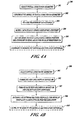
- Figure 4A is a flow diagram 200 that illustrates the method of the invention for a 2-D analysis as applied any given drive design, such as but not limited to the example in Figure 3 .
- initial lateral comb tooth geometry tooth thickness 120 and length 122, the lateral or side-gap 118, and the tooth overlap 114 dimensions, is selected as a function of overall design requirements and conventional fabrication design rules as are generally well-known in the art.
- the method of the invention is useful for minimizing or eliminating rectification in an existing design.
- measurements on theses parts provide the tooth geometry. Whether the comb tooth geometry is being currently designed, or is a pre-existing design, the analysis is the same.
- a finite element (FE) model is constructed of the initially selected or previously existing lateral comb tooth geometry.
- FE finite element
- a finite element model of the geometry is constructed using a computer aided design (CAD) program, by example and without limitation using either a proprietary or a commercially available CAD program such as "Ansoft.”
- CAD computer aided design
- a finite element analysis (FEA) calculation of capacitance is performed using the CAD program for both the selected initial overlap dimension 114 and for each of many different overlap dimension 114 both greater than and less than the initial overlap dimension 114.
- FEA finite element analysis
- Figure 5 is a graph 142 that illustrates the result of the series of FEA capacitance calculations for the example shown in Figure 3 .
- the graph 142 is a plot of capacitance versus the amount of tooth overlap 114 for a small range of engagement.
- Figure 6 is a graph 146 that illustrates the force versus overlap dimension 114 for the same small overlap range shown in Figure 5 , where the force is calculated using the equation above. It is well known in the art of electrostatic accelerometers that the force between the two capacitor plates embodied by the movable and fixed comb drive teeth 102, 104 is directly proportional to the partial derivative of the capacitance with respect to relative motion between the two capacitor plates so that the graph 146 illustrates the force-position relationship, where force is given in a force unit per volt 2 , and the overlap dimension 114 is again given in microns. An inflection point 126 is observed at the overlap dimension 114 that results in zero rectification.
- the inflection point 126 occurs along the curve of the graphed data, the inflection point 126 occurring at about the point commensurate with the 6.2 micron overlap dimension 114 in this example, where the 2nd derivative of the force relative to position is zero as it transverses between negative and positive values.
- the 3rd derivative of capacitance relative to position is proportional to the 2nd derivative of the force-displacement relation and so is also zero at the inflection point 126.
- the smooth behavior and two-fold symmetry of the force-position relationship shown in the graph 146 results in the average force being close to zero over any small region centered about this inflection point 126.
- the average of a force oscillating about this inflection point 126 is substantially the same as the static value at the inflection point 126. Therefore, the vibration rectification is near zero for overlap dimensions 114 in the vicinity of the inflection point 126.
- the capacitance versus position relationship is modeled mathematically using an appropriate mathematical method of curve fitting, such as a polynomial fit. Accordingly, well-known numerical methods are employed for analyzing the capacitance-versus-position relationship and determining a mathematical model of this relationship.
- a polynomial fit of the capacitance-versus-position relationship is performed, the polynomial fit is of at least 4th order or at least high enough that residuals from the fit are acceptably small for a given desired accuracy of the result
- the 1 st derivative of the polynomial is proportional to the force as a function of position.
- Block 205 the 3rd derivative of the capacitance versus position relationship is set to zero and solved for the overlap dimension 114 that forces it to zero.
- This overlap dimension 114 produces zero rectification. This determination of the zero-rectification overlap dimension 114 completes the definition of the tooth geometry.
- Figure 4B is a flow diagram 300 that illustrates an empirical alternative of the method of the invention wherein empirical data of measured rectification errors are relied upon, rather than finite element analysis of a model .
- empirical data of measured rectification errors are relied upon, rather than finite element analysis of a model .
- a series of different comb drives with different variations in tooth overlap 114 are built and tested. Curve fitting and interpolation of the resulting measured rectification errors leads to a geometry selection with low rectification.
- the tooth length 122 and lateral gap 118 dimensions are optionally allowed to very.
- the cooperative fixed and moveable teeth 102, 104 optionally differ from one another in shape.
- Many geometry variations are optionally allowed, and a "Design of Experiment" is utilized to arrive at a general optimized geometry, of which one goal is low rectification.
- initial lateral comb tooth geometry tooth thickness 120 and length 122, the lateral or side-gap 118, and the tooth overlap 114 dimensions, is selected as a function of overall design requirements and conventional fabrication design rules as are generally well-known in the art.
- a series of test specimens of the accelerometer or other device 100 of the invention are fabricated with variations in the tooth overlap 114 within a range of tooth overlap dimensions expected to be experienced in actual operation.
- the quantity of test specimens fabricated is a function of the desired accuracy of the result
- each test specimen of the accelerometer or other device 100 is placed on a vibration generator or "shaker head," and the test specimen of the accelerometer or other device 100 is vibrated along it's input axis I (shown in Figure 3 ) using the frequency and magnitude of vibration that is expected to be encountered in operation. Rectification data is collected using appropriate test equipment.
- Block 304 the rectification data collected in Block 302 is analyzed
- the selected range of tooth overlap dimensions 114 includes the tooth overlap dimension 114 that produces an acceptably low or zero rectification error
- the sign of the measured rectification error changes smoothly between negative and positive.
- This rectification data is interpolated to determine the overlap dimension 114 that produces low or zero rectification error. This determination of the zero-rectification overlap dimension 114 completes the definition of the tooth geometry.
- this gas-spring effects source of rectification is optionally eliminated simultaneously with the rectification source resulting from the manufactured geometry by commanding the proof mass 110 to move to a zero bias-rectification position.
- a gas-damped MEMS device contains small gaps between the moving proof mass 110 and adjacent static parts, i.e., the frame 112. In general, as the proof mass 110 moves in response to external input, some gaps are squeezed smaller while others are increased. The periodic motion of vibration leads to a periodic fluctuation in fluid forces on the proof mass 110.
- the error is optionally removed via a calibration procedure 400 of the invention. At least two different calibration methods 500 and 600 are contemplated by the invention for performing the calibration procedure 400.
- FIG. 7 is a flow diagram of one embodiment of the calibration method 500 for performing the calibration procedure 400 of the invention (shown in Figures 4A and 4B ).
- a bias voltage is bled into the capacitive pick-off circuit of the device 100 such that the servo drives the proof mass 110 to a non-zero pick-off differential capacitance. Adjusting this bias voltage in turn adjusts the position of the proof mass 110 relative to the frame 112.
- the accelerometer or other device 100 is placed on a vibration generator or "shaker head," and the accelerometer or other device 100 is vibrated along it's input axis I (shown in Figure 3 ).
- this bias voltage is adjusted until a balance in the fluid forces is found. The position where the fluid forces are balanced is a mean position of the proof mass 110 relative to the frame 112 where the rectification error is zero.
- FIG 8 is a flow diagram of one alternative calibration method 600 for performing the calibration procedure 400 of the invention (shown in Figures 4A and 4B ).
- the two capacitive pick-off sections in a closed-loop device 100 are each driven by an AC excitation voltage.
- the proof mass 110 is forced to the zero-rectification position by changing the amplitude of one of the two AC excitation voltages. This has the effect of changing an apparent differential capacitance between the two capacitive pick-off sections on either side of the proof mass 110 so that the rebalance circuit, or "servo," of the device 100 moves the proof mass 110 to a new position relative to the frame 112 that re-zeros the differential capacitance.
- the accelerometer or other device 100 is placed on a shaker head and vibrated along it's input axis I (shown in Figure 3 ).
- the excitation amplitude mismatch is adjusted to zero the rectification error during vibration of the accelerometer or other device 100.
- the force between the two capacitor plates embodied by the movable and fixed comb drive teeth 102, 104 is directly proportional to the partial derivative of the capacitance with respect to relative motion between the two capacitor plates.
- the infection point 126 in Figure 6 is observed at the overlap dimension 114 that results in zero rectification.
- the inflection point 126 thus occurs at about the overlap dimension 114 where the 2nd derivative of the force relative to position is zero as it transverses between negative and positive values.
- the 3rd derivative of capacitance relative to position is proportional to the 2nd derivative of the force-displacement relation and so is also zero at the inflection point 126.
- the smooth behavior and two-fold symmetry of the force-position relationship shown in the graph 146 indicates that the average of a force oscillating about this inflection point 126 is substantially the same as the static value at the inflection point 126, and the vibration rectification is near zero for overlap dimensions 114 in the vicinity of the inflection point 126.
- two methods are described for determining overlap dimensions 114 that result in near zero vibration rectification for a particular tooth geometry, according to other embodiments of the present invention, other methods for determining a relatively compact tooth geometry having the null position located such that the 2nd derivative of force relative to engagement position is substantially zero is equivalent to the methods described herein.
Landscapes
- Physics & Mathematics (AREA)
- General Physics & Mathematics (AREA)
- Engineering & Computer Science (AREA)
- Radar, Positioning & Navigation (AREA)
- Remote Sensing (AREA)
- Gyroscopes (AREA)
- Micromachines (AREA)
- Pressure Sensors (AREA)
Applications Claiming Priority (2)
| Application Number | Priority Date | Filing Date | Title |
|---|---|---|---|
| US11/068,692 US7720661B2 (en) | 2005-02-28 | 2005-02-28 | Low vibration rectification in a closed-loop, in-plane MEMS device |
| EP06734566A EP1853929B1 (de) | 2005-02-28 | 2006-02-09 | Berichtigung mit geringer vibration in einer mems-vorrichtung in der ebene mit geschlossenem regelkreis |
Related Parent Applications (2)
| Application Number | Title | Priority Date | Filing Date |
|---|---|---|---|
| EP06734566.0 Division | 2006-02-09 | ||
| EP06734566A Division EP1853929B1 (de) | 2005-02-28 | 2006-02-09 | Berichtigung mit geringer vibration in einer mems-vorrichtung in der ebene mit geschlossenem regelkreis |
Publications (2)
| Publication Number | Publication Date |
|---|---|
| EP2256504A1 true EP2256504A1 (de) | 2010-12-01 |
| EP2256504B1 EP2256504B1 (de) | 2012-08-22 |
Family
ID=36570636
Family Applications (2)
| Application Number | Title | Priority Date | Filing Date |
|---|---|---|---|
| EP06734566A Ceased EP1853929B1 (de) | 2005-02-28 | 2006-02-09 | Berichtigung mit geringer vibration in einer mems-vorrichtung in der ebene mit geschlossenem regelkreis |
| EP10173517A Ceased EP2256504B1 (de) | 2005-02-28 | 2006-02-09 | Korrektur fur kleine Vibrationen in einer closed-loop, planaren MEMS Vorrichtung. |
Family Applications Before (1)
| Application Number | Title | Priority Date | Filing Date |
|---|---|---|---|
| EP06734566A Ceased EP1853929B1 (de) | 2005-02-28 | 2006-02-09 | Berichtigung mit geringer vibration in einer mems-vorrichtung in der ebene mit geschlossenem regelkreis |
Country Status (5)
| Country | Link |
|---|---|
| US (2) | US7720661B2 (de) |
| EP (2) | EP1853929B1 (de) |
| JP (1) | JP4819832B2 (de) |
| DE (1) | DE602006016742D1 (de) |
| WO (1) | WO2006093637A2 (de) |
Cited By (1)
| Publication number | Priority date | Publication date | Assignee | Title |
|---|---|---|---|---|
| CN111551761A (zh) * | 2020-04-03 | 2020-08-18 | 四川知微传感技术有限公司 | 一种低噪声mems加速度计 |
Families Citing this family (9)
| Publication number | Priority date | Publication date | Assignee | Title |
|---|---|---|---|---|
| US7736361B2 (en) | 2003-02-14 | 2010-06-15 | The Board Of Trustees Of The Leland Stamford Junior University | Electrosurgical system with uniformly enhanced electric field and minimal collateral damage |
| US8215169B2 (en) | 2009-03-26 | 2012-07-10 | Honeywell International Inc. | Using pole pieces to guide magnetic flux through a MEMS device and method of making |
| US8166818B2 (en) * | 2009-03-26 | 2012-05-01 | Honeywell International Inc. | Using pole pieces to guide magnetic flux through a MEMS device and method of making |
| WO2011019879A1 (en) * | 2009-08-13 | 2011-02-17 | Endevco Corporation | Proof mass for maximized, bi-directional and symmetric damping in high g-range acceleration sensors |
| RU2475834C1 (ru) * | 2011-09-14 | 2013-02-20 | Открытое акционерное общество "Научно-производственное объединение "Сатурн" | Способ обеспечения вибрационной прочности деталей |
| DE102017115667A1 (de) * | 2017-07-12 | 2019-01-17 | Tdk Electronics Ag | Verfahren zum Messen eines Verhaltens eines MEMS-Bauelements |
| JP7234505B2 (ja) * | 2018-04-27 | 2023-03-08 | セイコーエプソン株式会社 | 振動整流誤差補正回路、物理量センサーモジュール、構造物監視装置及び振動整流誤差補正回路の補正値調整方法 |
| CN109752568B (zh) * | 2019-01-28 | 2020-12-04 | 南京理工大学 | 基于主成分分析的微电子机械系统加速度计标定方法 |
| CN109918780B (zh) * | 2019-03-06 | 2020-11-10 | 西安交通大学 | 一种面向高稳定性的微小锁紧机构弹性元件优化设计方法 |
Citations (1)
| Publication number | Priority date | Publication date | Assignee | Title |
|---|---|---|---|---|
| EP1160574A1 (de) * | 2000-06-02 | 2001-12-05 | Murata Manufacturing Co., Ltd. | Kapazitiver Detektor für äussere Kraft mit verbesserter Empfindlichkeit |
Family Cites Families (1)
| Publication number | Priority date | Publication date | Assignee | Title |
|---|---|---|---|---|
| JP2000180175A (ja) * | 1998-12-15 | 2000-06-30 | Mitsumi Electric Co Ltd | 多軸検出型角速度、加速度センサ |
-
2005
- 2005-02-28 US US11/068,692 patent/US7720661B2/en active Active
-
2006
- 2006-02-09 EP EP06734566A patent/EP1853929B1/de not_active Ceased
- 2006-02-09 WO PCT/US2006/004404 patent/WO2006093637A2/en not_active Ceased
- 2006-02-09 EP EP10173517A patent/EP2256504B1/de not_active Ceased
- 2006-02-09 JP JP2007558024A patent/JP4819832B2/ja not_active Expired - Fee Related
- 2006-02-09 DE DE602006016742T patent/DE602006016742D1/de not_active Expired - Lifetime
-
2010
- 2010-04-06 US US12/755,162 patent/US7949508B2/en not_active Expired - Lifetime
Patent Citations (1)
| Publication number | Priority date | Publication date | Assignee | Title |
|---|---|---|---|---|
| EP1160574A1 (de) * | 2000-06-02 | 2001-12-05 | Murata Manufacturing Co., Ltd. | Kapazitiver Detektor für äussere Kraft mit verbesserter Empfindlichkeit |
Non-Patent Citations (4)
| Title |
|---|
| AVDEEV, GYIMESI, LOVELL AND OSTERGAARD: "strongly coupled three-dimensional finite eleemnt transducter", JOURNAL OF MICROMECHANICS AND MICROENGINEERING, vol. 14, 2004, pages 1491 - 1502, XP002389891 * |
| GRADE, JERMAN, KENNY: "design of large deflection electrostatic actuators", JOURNAL OF MICROELECTROMECHANICAL SYSTEMS, vol. 12, no. 3, June 2003 (2003-06-01), pages 335 - 343, XP002389892 * |
| MOUSSA: "INVESTIGATING", CANADIAN JOURNAL OF ELECTRICAL AND COMPUTER ENGINEERING/ REVUE CANADIENNE DE GENIE ELECTRIQUE AND INFORMATIQUE, CANADIAN SOCIETY FOR ELECTRICAL AND COMPUTER, CA, vol. 27, no. 4, October 2002 (2002-10-01), pages 195 - 200, XP001237368, ISSN: 0840-8688 * |
| TAY F E H ET AL: "A differential capacitive low-g microaccelerometer with mg resolution", SENSORS AND ACTUATORS A, ELSEVIER SEQUOIA S.A., LAUSANNE, CH, vol. 86, no. 1-2, 30 October 2000 (2000-10-30), pages 45 - 51, XP004224527, ISSN: 0924-4247 * |
Cited By (1)
| Publication number | Priority date | Publication date | Assignee | Title |
|---|---|---|---|---|
| CN111551761A (zh) * | 2020-04-03 | 2020-08-18 | 四川知微传感技术有限公司 | 一种低噪声mems加速度计 |
Also Published As
| Publication number | Publication date |
|---|---|
| US20100198568A1 (en) | 2010-08-05 |
| US20060195305A1 (en) | 2006-08-31 |
| EP1853929B1 (de) | 2010-09-08 |
| JP4819832B2 (ja) | 2011-11-24 |
| JP2008533567A (ja) | 2008-08-21 |
| DE602006016742D1 (de) | 2010-10-21 |
| EP2256504B1 (de) | 2012-08-22 |
| EP1853929A2 (de) | 2007-11-14 |
| WO2006093637A3 (en) | 2007-01-11 |
| US7949508B2 (en) | 2011-05-24 |
| US7720661B2 (en) | 2010-05-18 |
| WO2006093637A2 (en) | 2006-09-08 |
Similar Documents
| Publication | Publication Date | Title |
|---|---|---|
| US7949508B2 (en) | Low vibration rectification in a closed-loop, in-plane MEMS device | |
| KR102126069B1 (ko) | 마이크로전기기계 시스템 및 이의 사용 방법들 | |
| Rocha et al. | Analysis and analytical modeling of static pull-in with application to MEMS-based voltage reference and process monitoring | |
| US8429954B2 (en) | Monolithic comb drive system and method for large-deflection multi-DOF microtransduction | |
| US7355318B2 (en) | Micromachined device utilizing electrostatic comb drives to filter mechanical vibrations | |
| EP2570770B1 (de) | Dreimassige gekoppelte oszillationstechnik für mechanisch robuste mikroverarbeitete gyroskope | |
| Frangi et al. | Optimization of sensing stators in capacitive MEMS operating at resonance | |
| CN111780736B (zh) | 微机械结构驱动幅度校正系统及方法 | |
| Nazdrowicz et al. | Analysis of temperature variation influence on capacitance inertial sensors parameters | |
| Turner et al. | Parametric resonance in a microelectromechanical torsional oscillator | |
| Noori | Analysis of 2: 1 internal resonance in mems applications | |
| Painter et al. | Effect of levitation forces on the performance of surface micromachined MEMS gyroscopes | |
| CN119716143B (zh) | 一种基于多模态微机械检测的加速度测量方法 | |
| Xing et al. | A Broadband and Low Damping Piezoelectric MEMS Vibration Platform for 6-DOF Inertial Motion | |
| Gridchin et al. | Geometric Parameterized Macromodel of Uniaxial Capacitance Accelerometer Based on Modal Superposition | |
| Yeh et al. | Mathematical modelling on the quadrature error of low-rate microgyroscope for aerospace applications | |
| Chen | Analysis of Loss Mechanisms and Frequency Mismatch in Microelectromechanical Systems (MEMS)-Based Resonators | |
| Voßkämper¹ et al. | Modeling Micro-Mechanical Structures for System Simulations | |
| Sarrafan | Angular rate sensing using nonlinear microresonators actuated by 2: 1 internal resonance | |
| EP2154538A2 (de) | Beschleunigungssensor und Verfahren zum Erfassen einer Beschleunigung | |
| Holovatyy et al. | VHDL-AMS model of mechanical elements of MEMS tuning fork gyroscope for the schematic level of computer-aided design | |
| Guo | Bi-state control of microelectromechanical nonlinear and parametric resonance | |
| Nafissi | Design of an Integrated Electrostatic Atomic Force Microscope | |
| GB2401945A (en) | Atomic force microscope (AFM) cantilever calibration | |
| CN121703454A (zh) | 一种垂直变面积的差分电容式加速度计 |
Legal Events
| Date | Code | Title | Description |
|---|---|---|---|
| PUAI | Public reference made under article 153(3) epc to a published international application that has entered the european phase |
Free format text: ORIGINAL CODE: 0009012 |
|
| AC | Divisional application: reference to earlier application |
Ref document number: 1853929 Country of ref document: EP Kind code of ref document: P |
|
| AK | Designated contracting states |
Kind code of ref document: A1 Designated state(s): CH DE GB LI |
|
| 17P | Request for examination filed |
Effective date: 20110520 |
|
| RIC1 | Information provided on ipc code assigned before grant |
Ipc: G01P 21/00 20060101AFI20111014BHEP Ipc: G01P 15/08 20060101ALI20111014BHEP |
|
| GRAP | Despatch of communication of intention to grant a patent |
Free format text: ORIGINAL CODE: EPIDOSNIGR1 |
|
| GRAS | Grant fee paid |
Free format text: ORIGINAL CODE: EPIDOSNIGR3 |
|
| GRAA | (expected) grant |
Free format text: ORIGINAL CODE: 0009210 |
|
| AC | Divisional application: reference to earlier application |
Ref document number: 1853929 Country of ref document: EP Kind code of ref document: P |
|
| AK | Designated contracting states |
Kind code of ref document: B1 Designated state(s): CH DE GB LI |
|
| REG | Reference to a national code |
Ref country code: GB Ref legal event code: FG4D |
|
| REG | Reference to a national code |
Ref country code: CH Ref legal event code: EP |
|
| REG | Reference to a national code |
Ref country code: DE Ref legal event code: R096 Ref document number: 602006031667 Country of ref document: DE Effective date: 20121018 |
|
| PLBE | No opposition filed within time limit |
Free format text: ORIGINAL CODE: 0009261 |
|
| STAA | Information on the status of an ep patent application or granted ep patent |
Free format text: STATUS: NO OPPOSITION FILED WITHIN TIME LIMIT |
|
| 26N | No opposition filed |
Effective date: 20130523 |
|
| REG | Reference to a national code |
Ref country code: DE Ref legal event code: R097 Ref document number: 602006031667 Country of ref document: DE Effective date: 20130523 |
|
| PGFP | Annual fee paid to national office [announced via postgrant information from national office to epo] |
Ref country code: DE Payment date: 20160302 Year of fee payment: 11 Ref country code: CH Payment date: 20160125 Year of fee payment: 11 |
|
| PGFP | Annual fee paid to national office [announced via postgrant information from national office to epo] |
Ref country code: GB Payment date: 20160127 Year of fee payment: 11 |
|
| REG | Reference to a national code |
Ref country code: DE Ref legal event code: R119 Ref document number: 602006031667 Country of ref document: DE |
|
| REG | Reference to a national code |
Ref country code: CH Ref legal event code: PL |
|
| GBPC | Gb: european patent ceased through non-payment of renewal fee |
Effective date: 20170209 |
|
| PG25 | Lapsed in a contracting state [announced via postgrant information from national office to epo] |
Ref country code: LI Free format text: LAPSE BECAUSE OF NON-PAYMENT OF DUE FEES Effective date: 20170228 Ref country code: CH Free format text: LAPSE BECAUSE OF NON-PAYMENT OF DUE FEES Effective date: 20170228 |
|
| PG25 | Lapsed in a contracting state [announced via postgrant information from national office to epo] |
Ref country code: DE Free format text: LAPSE BECAUSE OF NON-PAYMENT OF DUE FEES Effective date: 20170901 |
|
| PG25 | Lapsed in a contracting state [announced via postgrant information from national office to epo] |
Ref country code: GB Free format text: LAPSE BECAUSE OF NON-PAYMENT OF DUE FEES Effective date: 20170209 |
|
| P01 | Opt-out of the competence of the unified patent court (upc) registered |
Effective date: 20230525 |