EP2256416A2 - Support assembly - Google Patents
Support assembly Download PDFInfo
- Publication number
- EP2256416A2 EP2256416A2 EP10161620A EP10161620A EP2256416A2 EP 2256416 A2 EP2256416 A2 EP 2256416A2 EP 10161620 A EP10161620 A EP 10161620A EP 10161620 A EP10161620 A EP 10161620A EP 2256416 A2 EP2256416 A2 EP 2256416A2
- Authority
- EP
- European Patent Office
- Prior art keywords
- support
- board
- support surface
- support element
- locking
- Prior art date
- Legal status (The legal status is an assumption and is not a legal conclusion. Google has not performed a legal analysis and makes no representation as to the accuracy of the status listed.)
- Granted
Links
- 229910052751 metal Inorganic materials 0.000 claims description 28
- 239000002184 metal Substances 0.000 claims description 28
- 230000006698 induction Effects 0.000 claims description 11
- 230000015572 biosynthetic process Effects 0.000 claims description 5
- 238000010438 heat treatment Methods 0.000 claims description 2
- 238000001816 cooling Methods 0.000 description 9
- 238000005755 formation reaction Methods 0.000 description 4
- BASFCYQUMIYNBI-UHFFFAOYSA-N platinum Chemical compound [Pt] BASFCYQUMIYNBI-UHFFFAOYSA-N 0.000 description 3
- 238000011161 development Methods 0.000 description 2
- 230000018109 developmental process Effects 0.000 description 2
- 230000001404 mediated effect Effects 0.000 description 2
- 238000000465 moulding Methods 0.000 description 2
- 229910052782 aluminium Inorganic materials 0.000 description 1
- XAGFODPZIPBFFR-UHFFFAOYSA-N aluminium Chemical compound [Al] XAGFODPZIPBFFR-UHFFFAOYSA-N 0.000 description 1
- 238000007664 blowing Methods 0.000 description 1
- 238000005553 drilling Methods 0.000 description 1
Images

Classifications
-
- F—MECHANICAL ENGINEERING; LIGHTING; HEATING; WEAPONS; BLASTING
- F24—HEATING; RANGES; VENTILATING
- F24C—DOMESTIC STOVES OR RANGES ; DETAILS OF DOMESTIC STOVES OR RANGES, OF GENERAL APPLICATION
- F24C7/00—Stoves or ranges heated by electric energy
- F24C7/08—Arrangement or mounting of control or safety devices
- F24C7/082—Arrangement or mounting of control or safety devices on ranges, e.g. control panels, illumination
-
- F—MECHANICAL ENGINEERING; LIGHTING; HEATING; WEAPONS; BLASTING
- F24—HEATING; RANGES; VENTILATING
- F24C—DOMESTIC STOVES OR RANGES ; DETAILS OF DOMESTIC STOVES OR RANGES, OF GENERAL APPLICATION
- F24C15/00—Details
- F24C15/08—Foundations or supports plates; Legs or pillars; Casings; Wheels
-
- F—MECHANICAL ENGINEERING; LIGHTING; HEATING; WEAPONS; BLASTING
- F24—HEATING; RANGES; VENTILATING
- F24C—DOMESTIC STOVES OR RANGES ; DETAILS OF DOMESTIC STOVES OR RANGES, OF GENERAL APPLICATION
- F24C15/00—Details
- F24C15/10—Tops, e.g. hot plates; Rings
- F24C15/102—Tops, e.g. hot plates; Rings electrically heated
-
- H—ELECTRICITY
- H05—ELECTRIC TECHNIQUES NOT OTHERWISE PROVIDED FOR
- H05B—ELECTRIC HEATING; ELECTRIC LIGHT SOURCES NOT OTHERWISE PROVIDED FOR; CIRCUIT ARRANGEMENTS FOR ELECTRIC LIGHT SOURCES, IN GENERAL
- H05B6/00—Heating by electric, magnetic or electromagnetic fields
- H05B6/02—Induction heating
Definitions
- the invention relates to a carrier arrangement with at least one electrically insulating support element for supporting a circuit board on a floor and in a hob with such a carrier arrangement.
- the power electronics necessary for operating the inductors are mounted together with cooling elements on large-area circuit boards.
- These boards are supported via carrier arrangements with at least one electrically insulating support element in a metal bottom of a hob housing.
- the support elements used hitherto comprise not only a support surface on which rests the board, but also four lateral stops, which limit freedom of movement of the board in the plane extending parallel to the support surface. These support elements are therefore just as large as the board and are adapted to the large shape of the board. For different series of a hob and / or structural changes in the shape of the board, the support element must be adjusted.
- the carrier device makes the hob structurally inflexible and leads to high development costs.
- the invention is in particular the object of providing a flexible and adaptable to various board shape and board sizes carrier assembly and equip a hob with such an improved carrier assembly.
- the invention is based on a carrier arrangement with at least one electrically insulating support element for supporting a circuit board on a floor.
- the support element may in particular be made of plastic.
- the support element encompasses exactly one corner area of the board, in which two side edges of the board meet.
- a particularly flexible carrier arrangement which can be adapted to the size and shape can thus be achieved.
- Each at least substantially rectangular, in particular rectangular board can be easily supported by a support element is placed at each of the corners.
- the support element thus forms a kind of angle part, which supports the board at a corner or in the corner area.
- the support element comprises a support surface and at least two stops aligned perpendicular to the support surface for limiting a freedom of movement of the circuit board in a direction parallel to the support surface. This allows the board to be easily mounted and securely held.
- a secure attachment of the board can be achieved if the support element comprises a structure for fixing the board in a direction facing away from the support surface direction.
- the structure may in particular comprise a detent which prevents the board from lifting off the support surface.
- connection to the metal floor can be made safely and easily if the support element on a side facing away from the support surface at least a positive locking element for engagement in a corresponding recess in the metal bottom comprises.
- this form-fitting element may comprise a latching nose for engaging behind an edge of an opening in the metal floor. This opening can be incorporated in a survey or molding in the metal floor, so that the locking elements of the support member does not project beyond a back of the metal floor.
- the locking lug on the underside of the support member may be formed in a particularly advantageous embodiment of the invention to a parallel to the support surface elastic spring leg of the support member.
- a secure latching connection can be made possible if the carrier arrangement comprises at least one pair of latching lugs aligned in opposite directions, which can in particular be formed on parallel spring legs.
- the carrier arrangement according to the invention is particularly suitable for holding a circuit board which carries the power electronics for operating induction heating elements.
- Such boards often carry comparatively heavy cooling elements, so that a secure hold at the same time high cost efficiency is particularly important.
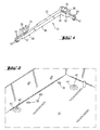
- Fig. 1 shows a support element 10 of a carrier assembly for carrying a power
- the entire support member 10 and the support surface are L-shaped, wherein one of the legs of the L-shape is significantly longer than the other leg.
- Each of the stops 24, 26 is arranged on one of the mutually perpendicular legs. The stops 24, 26 are also aligned at right angles to each other, so that they run parallel to the side edges 18, 20 of the board 12.
- a detent 28, 30 is formed, which prevents lifting of the board 12 of the support surface 22.
- Below the locking lugs 28, 30 openings 32, 34 are provided, in which for releasing a mediated by the locking lugs 28, 30 locking connection tools can be introduced.
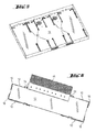
- Fig. 7 shows a sectional view of the metal bottom 14 with the formation 43 and the opening 42, in which the locking lugs 40 engage. It can be seen that the tips of the locking lugs 40 are completely sunk by the hollow formed by the back of the molding, so that the hob according to the invention can be easily mounted and / or stacked.
Landscapes
- Engineering & Computer Science (AREA)
- Chemical & Material Sciences (AREA)
- Combustion & Propulsion (AREA)
- Mechanical Engineering (AREA)
- General Engineering & Computer Science (AREA)
- Physics & Mathematics (AREA)
- Electromagnetism (AREA)
- Cookers (AREA)
- Baking, Grill, Roasting (AREA)
- Mounting Of Printed Circuit Boards And The Like (AREA)
- Shielding Devices Or Components To Electric Or Magnetic Fields (AREA)
- Packaging Of Annular Or Rod-Shaped Articles, Wearing Apparel, Cassettes, Or The Like (AREA)
Abstract
Description
Die Erfindung betrifft eine Trägeranordnung mit wenigstens einem elektrisch isolierenden Stützelement zum Abstützen einer Platine auf einem Boden und in ein Kochfeld mit einer solchen Trägeranordnung.The invention relates to a carrier arrangement with at least one electrically insulating support element for supporting a circuit board on a floor and in a hob with such a carrier arrangement.
Insbesondere in Induktionskochfeldern wird die zum Betreiben der Induktoren notwenige Leistungselektronik zusammen mit Kühlelementen auf großflächige Platinen montiert. Diese Platinen werden über Trägeranordnungen mit wenigstens einem elektrisch isolierenden Stützelement in einen Metallboden eines Kochfeldgehäuses abgestützt. Die bislang verwendeten Stützelemente umfassen neben einer Auflagefläche, auf der die Platine aufliegt, auch vier seitliche Anschläge, die eine Bewegungsfreiheit der Platine in der parallel zur Auflagefläche verlaufenden Ebene begrenzen. Diese Stützelemente sind daher ebenso großflächig wie die Platine und sind an die große Form der Platine angepasst. Für unterschiedliche Baureihen eines Kochfelds und/oder konstruktive Änderungen in der Form der Platine muss das Stützelement angepasst werden. Die Trägervorrichtung macht das Kochfeld in konstruktiver Hinsicht unflexibel und führt zu hohen Entwicklungskosten.In particular in induction hobs, the power electronics necessary for operating the inductors are mounted together with cooling elements on large-area circuit boards. These boards are supported via carrier arrangements with at least one electrically insulating support element in a metal bottom of a hob housing. The support elements used hitherto comprise not only a support surface on which rests the board, but also four lateral stops, which limit freedom of movement of the board in the plane extending parallel to the support surface. These support elements are therefore just as large as the board and are adapted to the large shape of the board. For different series of a hob and / or structural changes in the shape of the board, the support element must be adjusted. The carrier device makes the hob structurally inflexible and leads to high development costs.
Der Erfindung liegt insbesondere die Aufgabe zugrunde, eine flexible und an verschiedene Platinenform und Platinengrößen anpassbare Trägeranordnung bereitzustellen und ein Kochfeld mit einer derart verbesserten Trägeranordnung auszustatten.The invention is in particular the object of providing a flexible and adaptable to various board shape and board sizes carrier assembly and equip a hob with such an improved carrier assembly.
Die Aufgabe wird insbesondere durch eine Trägeranordnung mit den Merkmalen des Anspruchs 1 gelöst. Vorteilhafte Ausgestaltungen und Weiterbildungen ergeben sich aus den Unteransprüchen.The object is achieved in particular by a carrier arrangement having the features of
Die Erfindung geht aus von einer Trägeranordnung mit wenigstens einem elektrisch isolierenden Stützelement zum Abstützen einer Platine auf einem Boden, insbesondere aus Metall. Das Stützelement kann insbesondere aus Kunststoff gefertigt sein.The invention is based on a carrier arrangement with at least one electrically insulating support element for supporting a circuit board on a floor. in particular of metal. The support element may in particular be made of plastic.
Es wird vorgeschlagen, dass das Stützelement genau einen Eckbereich der Platine umgreift, in dem zwei Seitenkanten der Platine aufeinandertreffen. Im Vergleich zu Stützelementen, die die Platine vollständig umgeben, ist so eine besonders flexible an die Größe und Form anpassbare Trägeranordnung erreichbar. Jede zumindest im Wesentlichen rechtwinkelige, insbesondere rechteckige Platine kann einfach abgestützt werden, indem an jede der Ecken ein Stützelement gesetzt wird. Das Stützelement bildet demnach eine Art Winkelteil, das die Platine an einer Ecke bzw. in dem Eckbereich abstützt.It is proposed that the support element encompasses exactly one corner area of the board, in which two side edges of the board meet. In comparison to support elements which completely surround the circuit board, a particularly flexible carrier arrangement which can be adapted to the size and shape can thus be achieved. Each at least substantially rectangular, in particular rectangular board can be easily supported by a support element is placed at each of the corners. The support element thus forms a kind of angle part, which supports the board at a corner or in the corner area.
Ferner wird vorgeschlagen, dass das Stützelement eine Auflagefläche und wenigstens zwei senkrecht zur Auflagefläche ausgerichtete Anschläge zum Begrenzen einer Bewegungsfreiheit der Platine in eine Richtung parallel zur Auflagefläche umfasst. Dadurch kann die Platine einfach montiert und sicher gehalten werden.It is also proposed that the support element comprises a support surface and at least two stops aligned perpendicular to the support surface for limiting a freedom of movement of the circuit board in a direction parallel to the support surface. This allows the board to be easily mounted and securely held.
Eine sichere Befestigung der Platine kann erreicht werden, wenn das Stützelement eine Struktur zum Fixieren der Platine in einer von der Auflagefläche abgewandten Richtung umfasst. Die Struktur kann insbesondere eine Rastnase umfassen, die ein Abheben der Platine von der Auflagefläche verhindert.A secure attachment of the board can be achieved if the support element comprises a structure for fixing the board in a direction facing away from the support surface direction. The structure may in particular comprise a detent which prevents the board from lifting off the support surface.
Die Anschläge des Stützelements können in einer vorteilhaften Ausgestaltung eine Rastnase umfassen, so dass die Trägeranordnung die Platine in allen Richtungen formschlüssig halten kann. In einer besonders vorteilhaften Ausgestaltung der Erfindung umfasst die Auflagefläche und/oder wenigstens einer der Anschläge unterhalb der Rastnase eine Öffnung. In diese Öffnung kann ein Werkzeug zum Lösen der Rastverbindung eingeführt werden.The stops of the support member may comprise a locking lug in an advantageous embodiment, so that the support assembly can hold the board in all directions form-fitting manner. In a particularly advantageous embodiment of the invention, the support surface and / or at least one of the stops below the locking lug comprises an opening. In this opening, a tool for releasing the locking connection can be introduced.
Die Verbindung mit dem Metallboden kann sicher und einfach hergestellt werden, wenn das Stützelement an einer der Auflagefläche abgewandten Seite wenigstens ein Formschlusselement zum Eingriff in eine entsprechende Ausnehmung im Metallboden umfasst. Dieses Formschlusselement kann in einer besonders vorteilhaften Ausgestaltung der Erfindung eine Rastnase zum Hintergreifen eines Rands einer Öffnung im Metallboden umfassen. Diese Öffnung kann in eine Erhebung bzw. Ausformung im Metallboden eingearbeitet sein, so dass die Rastelemente des Stützelements eine Rückseite des Metallbodens nicht überragen. Die Rastnase an der Unterseite des Stützelements kann in einer besonders vorteilhaften Ausgestaltung der Erfindung an einen parallel zu der Auflagefläche elastischen Federschenkel des Stützelements angeformt sein. Eine sichere Rastverbindung kann ermöglicht werden, wenn die Trägeranordnung wenigstens ein Paar von in entgegengesetzte Richtungen ausgerichteten Rastnasen umfasst, die insbesondere an parallel verlaufenden Federschenkel angeformt sein können.The connection to the metal floor can be made safely and easily if the support element on a side facing away from the support surface at least a positive locking element for engagement in a corresponding recess in the metal bottom comprises. In a particularly advantageous embodiment of the invention, this form-fitting element may comprise a latching nose for engaging behind an edge of an opening in the metal floor. This opening can be incorporated in a survey or molding in the metal floor, so that the locking elements of the support member does not project beyond a back of the metal floor. The locking lug on the underside of the support member may be formed in a particularly advantageous embodiment of the invention to a parallel to the support surface elastic spring leg of the support member. A secure latching connection can be made possible if the carrier arrangement comprises at least one pair of latching lugs aligned in opposite directions, which can in particular be formed on parallel spring legs.
Zum Halten einer rechteckigen Platine kann die Trägeranordnung insbesondere vier gleichartige Stützelemente zum Halten der vier Ecken einer einzigen Platine umfassen. Als gleichartig sollen in diesem Zusammenhang, insbesondere Stützelemente bezeichnet werden, deren Formen durch Spiegelungen auseinander hervorgehen.For holding a rectangular board, the support arrangement may in particular comprise four similar support elements for holding the four corners of a single board. As similar should be referred to in this context, in particular support elements whose shapes emerge apart by reflections.
Die erfindungsgemäße Trägeranordnung ist wegen ihrer Flexibilität und hohen Kosteneffizienz insbesondere zum Halten einer Platine geeignet, welche die Leistungselektronik zum Betreiben von Induktionsheizelementen trägt. Solche Platinen tragen häufig auch vergleichsweise schwere Kühlelemente, so dass ein sicherer Halt bei gleichzeitig hoher Kosteneffizienz besonders wichtig ist.Because of its flexibility and high cost efficiency, the carrier arrangement according to the invention is particularly suitable for holding a circuit board which carries the power electronics for operating induction heating elements. Such boards often carry comparatively heavy cooling elements, so that a secure hold at the same time high cost efficiency is particularly important.
Weitere vorteilhafte Merkmale ergeben sich aus der folgenden Figurenbeschreibung. Die Figurenbeschreibung betrifft ein Ausführungsbeispiel der Erfindung und enthält wie auch die Ansprüche und die Figuren zahlreiche Merkmale in einer speziellen Kombination, die der Fachmann sinnvoller Weise auch einzeln betrachtet und zur weiteren Kombination zusammenfasst.Further advantageous features will become apparent from the following description of the figures. The description of the figures relates to an exemplary embodiment of the invention and, like the claims and the figures, contains numerous features in a special combination, which the skilled person also sensibly considers individually and summarizes for further combination.
Dabei zeigen:
- Fig. 1
- ein Stützelement einer Trägeranordnung zum Abstützen einer Platine auf einem Metallboden nach einer ersten Ausgestaltung der Erfindung,
- Fig. 2
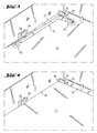
- einen Metallboden eines Kochfeldgehäuses eines Induk- tionskochfelds mit mehreren Löchern zum Fixieren eines Stützelements gemäß
Fig. 1 , - Fig. 3
- das in dem Metallboden nach
Fig. 2 eingesetzte Stütz- element gemäßFig. 1 , - Fig. 4
- die Anordnung aus
Fig. 3 mit einer eingesetzten Platine, - Fig. 5
- eine schematische Darstellung eines Metallbodens mit 16 Stützelementen zum Tragen von insgesamt 4 Platinen ei- nes Induktionskochfelds,
- Fig. 6
- eine Platine mit vier Stützelementen einer Trägeranord- nung und einem Kühlelement und
- Fig. 7
- eine Schnittdarstellung eines erfindungsgemäßen Stütz- elements und eines Metallbodens.
- Fig. 1
- a support element of a support arrangement for supporting a circuit board on a metal floor according to a first embodiment of the invention,
- Fig. 2
- a metal bottom of a cooktop housing an induction cooktop with a plurality of holes for fixing a support member according to
Fig. 1 . - Fig. 3
- in the metal floor
Fig. 2 used support element according toFig. 1 . - Fig. 4
- the arrangement
Fig. 3 with an inserted board, - Fig. 5
- a schematic representation of a metal floor with 16 support elements for supporting a total of 4 boards of an induction hob,
- Fig. 6
- a board with four support elements of a carrier arrangement and a cooling element and
- Fig. 7
- a sectional view of a support element according to the invention and a metal floor.
elektronik-Platine 12 (
Das gesamte Stützelement 10 und die Auflagefläche sind L-förmig ausgebildet, wobei einer der Schenkel der L-Form deutlich länger ist als der andere Schenkel. Jeder der Anschläge 24, 26 ist an einem der rechtwinklig zueinander verlaufenden Schenkel angeordnet. Die Anschläge 24, 26 sind ebenfalls rechtwinkelig zueinander ausgerichtet, so dass sie parallel zu den Seitenkanten 18, 20 der Platine 12 verlaufen. An jedem der Anschläge 24, 26 ist eine Rastnase 28, 30 angeformt, die ein Abheben der Platine 12 von der Auflagefläche 22 verhindert. Unterhalb der Rastnasen 28, 30 sind jeweils Öffnungen 32, 34 vorgesehen, in welche zum Lösen einer durch die Rastnasen 28, 30 vermittelten Rastverbindung Werkzeuge eingeführt werden können.The
An einer der Auflagefläche 22 abgewandten Rückseite des Stützelements 10 ist dieses mit verschiedenen Formschlusselementen zum Herstellen einer formschlüssigen Verbindung mit dem Metallboden 14 ausgestattet. Die Formschlusselemente umfassen drei Stifte 36 zum Eingreifen in Bohrungen 38 (
- 1010
- Stützelementsupport element
- 1212
- Platinecircuit board
- 1414
- Metallbodenmetal floor
- 1616
- Eckbereichcorner
- 1818
- Seitenkanteside edge
- 2020
- Seitenkanteside edge
- 2222
- Auflageflächebearing surface
- 2424
- Anschlagattack
- 2626
- Anschlagattack
- 2828
- Rastnaselocking lug
- 3030
- Rastnaselocking lug
- 3232
- Öffnungopening
- 3434
- Öffnungopening
- 3636
- Stiftepencils
- 3838
- Bohrungdrilling
- 4040
- Rastnaselocking lug
- 4242
- Öffnungopening
- 4343
- Ausformungformation
- 4444
- Federschenkelspring leg
- 4646
- Kühlelementcooling element
Claims (13)
dadurch gekennzeichnet, dass das Stützelement (10) genau einen Eckbereich (16) der Platine (12) umgreift, in dem zwei Seitenkanten (18, 20) der Platine (12) aufeinandertreffen.Carrier arrangement with at least one electrically insulating support element (10) for supporting a circuit board (12) on a floor (14),
characterized in that the support element (10) engages exactly one corner region (16) of the board (12) in which two side edges (18, 20) of the board (12) meet.
Applications Claiming Priority (1)
| Application Number | Priority Date | Filing Date | Title |
|---|---|---|---|
| ES200930208A ES2386227B1 (en) | 2009-05-26 | 2009-05-26 | SUPPORT PROVISION OF A PLATE FOR AN INDUCTION COOKING FIELD AND SUCH COOKING FIELD. |
Publications (3)
| Publication Number | Publication Date |
|---|---|
| EP2256416A2 true EP2256416A2 (en) | 2010-12-01 |
| EP2256416A3 EP2256416A3 (en) | 2012-07-25 |
| EP2256416B1 EP2256416B1 (en) | 2015-01-14 |
Family
ID=42732487
Family Applications (1)
| Application Number | Title | Priority Date | Filing Date |
|---|---|---|---|
| EP10161620.9A Active EP2256416B1 (en) | 2009-05-26 | 2010-04-30 | Support assembly |
Country Status (2)
| Country | Link |
|---|---|
| EP (1) | EP2256416B1 (en) |
| ES (2) | ES2386227B1 (en) |
Cited By (5)
| Publication number | Priority date | Publication date | Assignee | Title |
|---|---|---|---|---|
| EP2498577A3 (en) * | 2011-03-10 | 2013-04-17 | BSH Bosch und Siemens Hausgeräte GmbH | Assembly for a hob and induction hob with such an assembly |
| EP2703724A1 (en) * | 2012-09-03 | 2014-03-05 | BSH Bosch und Siemens Hausgeräte GmbH | Device for a domestic appliance |
| EP3029381A1 (en) | 2014-12-03 | 2016-06-08 | BSH Hausgeräte GmbH | Hotplate device |
| EP3076754A1 (en) * | 2015-03-30 | 2016-10-05 | Whirlpool Corporation | Induction cooking appliance and method for its assembling |
| DE102016202983B4 (en) | 2015-03-18 | 2024-03-14 | BSH Hausgeräte GmbH | Hob device |
Family Cites Families (9)
| Publication number | Priority date | Publication date | Assignee | Title |
|---|---|---|---|---|
| GB2100853B (en) * | 1981-06-23 | 1985-02-06 | Bosch Siemens Hausgeraete | Kitchen installation with built-in cooker hob |
| JPH0235902B2 (en) * | 1982-07-22 | 1990-08-14 | Matsushita Electric Ind Co Ltd | KANETSUCHORIKI |
| DE10003410A1 (en) * | 2000-01-27 | 2001-08-16 | Aeg Hausgeraete Gmbh | Household appliance, in particular household cooking appliance |
| DE10015973B4 (en) * | 2000-03-30 | 2007-04-12 | AEG Hausgeräte GmbH | Household appliance, in particular household cooking appliance |
| DE202004008515U1 (en) * | 2004-05-26 | 2004-09-23 | BSH Bosch und Siemens Hausgeräte GmbH | Induction cool top platform for a domestic cooker hob has a cool top platform plate and an inductor fitted underneath in a housing with a base and radiation heating elements in the housing |
| DE102005008901A1 (en) * | 2005-02-26 | 2006-08-31 | Electrolux Home Products Corporation N.V. | hob |
| JP4382731B2 (en) * | 2005-09-28 | 2009-12-16 | エヌイーシーコンピュータテクノ株式会社 | Printed circuit board holding mechanism |
| KR20080078760A (en) * | 2007-02-24 | 2008-08-28 | 엘지전자 주식회사 | Induction heating device |
| ES2336408B1 (en) * | 2008-02-22 | 2011-02-10 | Bsh Electrodomesticos España, S.A. | DOMESTIC DEVICE WITH A USER INTERFACE SENSITIVE TO CONTACT. |
-
2009
- 2009-05-26 ES ES200930208A patent/ES2386227B1/en not_active Revoked
-
2010
- 2010-04-30 EP EP10161620.9A patent/EP2256416B1/en active Active
- 2010-04-30 ES ES10161620.9T patent/ES2528423T3/en active Active
Non-Patent Citations (1)
| Title |
|---|
| None |
Cited By (9)
| Publication number | Priority date | Publication date | Assignee | Title |
|---|---|---|---|---|
| EP2498577A3 (en) * | 2011-03-10 | 2013-04-17 | BSH Bosch und Siemens Hausgeräte GmbH | Assembly for a hob and induction hob with such an assembly |
| ES2401261R1 (en) * | 2011-03-10 | 2013-04-25 | Bsh Electrodomesticos Espana | Arrangement for a cooking field, and induction cooking field with a corresponding arrangement |
| EP2703724A1 (en) * | 2012-09-03 | 2014-03-05 | BSH Bosch und Siemens Hausgeräte GmbH | Device for a domestic appliance |
| EP3029381A1 (en) | 2014-12-03 | 2016-06-08 | BSH Hausgeräte GmbH | Hotplate device |
| DE102016202983B4 (en) | 2015-03-18 | 2024-03-14 | BSH Hausgeräte GmbH | Hob device |
| EP3076754A1 (en) * | 2015-03-30 | 2016-10-05 | Whirlpool Corporation | Induction cooking appliance and method for its assembling |
| US20160295644A1 (en) * | 2015-03-30 | 2016-10-06 | Whirlpool Corporation | Induction cooking appliance and method for its assembly |
| US10349469B2 (en) * | 2015-03-30 | 2019-07-09 | Whirlpool Corporation | Induction cooking appliance and method for its assembly |
| US11369009B2 (en) * | 2015-03-30 | 2022-06-21 | Whirlpool Corporation | Induction cooking appliance and method for its assembly |
Also Published As
| Publication number | Publication date |
|---|---|
| ES2528423T3 (en) | 2015-02-09 |
| EP2256416B1 (en) | 2015-01-14 |
| EP2256416A3 (en) | 2012-07-25 |
| ES2386227B1 (en) | 2013-06-24 |
| ES2386227A1 (en) | 2012-08-13 |
Similar Documents
| Publication | Publication Date | Title |
|---|---|---|
| EP2427032B1 (en) | Hotplate device | |
| EP2256416B1 (en) | Support assembly | |
| EP2703724B1 (en) | Device for a cooking hob and method for assembling a device for a cooking hob | |
| DE3513910C2 (en) | Solar panel | |
| EP3257121B1 (en) | Arrangement of multiple latching feet for an assembly | |
| EP2602556A2 (en) | Hotplate device | |
| DE102017126532A1 (en) | Printed circuit board assembly of at least two printed circuit boards | |
| DE102018000786A1 (en) | Housing mounting arrangement | |
| EP2036409A1 (en) | Screening element for electronic units | |
| DE102016122388A1 (en) | Luminous element and arrangement with a luminous element | |
| EP2703725A2 (en) | Hotplate device | |
| EP0465693B1 (en) | Electrical insulating printed circuit board with integrated cooling means | |
| WO2016008905A1 (en) | Display device comprising a display and household appliance comprising said display device | |
| DE7015344U (en) | CARD HOLDER FOR CARDS WITH ELECTRIC CIRCUITS. | |
| DE102014221785A1 (en) | Household appliance with an input device comprising a flexible film | |
| WO2019072987A1 (en) | Electronics housing and subrack | |
| EP2703726A1 (en) | Hotplate device | |
| DE102012112393B4 (en) | Electrical assembly | |
| EP2645002A2 (en) | Household operating device | |
| DE102012101829A1 (en) | Induction hob used in kitchen, has control and power electronic unit that is provided with contact device whose contact region is arranged within aperture above supporting metal sheet | |
| CN209303835U (en) | A kind of chamfer machining auxiliary device | |
| DE112017004078T5 (en) | maker | |
| DE102008017776A1 (en) | Cooking hob housing containing device for cooker has spring element made in one with cooking hob housing | |
| EP3339724B1 (en) | Luminaire with mounting track and fastening element for a circuit board | |
| DE102016213049A1 (en) | Arrangement and reduction of the vibration behavior of electronic components |
Legal Events
| Date | Code | Title | Description |
|---|---|---|---|
| PUAI | Public reference made under article 153(3) epc to a published international application that has entered the european phase |
Free format text: ORIGINAL CODE: 0009012 |
|
| AK | Designated contracting states |
Kind code of ref document: A2 Designated state(s): AT BE BG CH CY CZ DE DK EE ES FI FR GB GR HR HU IE IS IT LI LT LU LV MC MK MT NL NO PL PT RO SE SI SK SM TR |
|
| AX | Request for extension of the european patent |
Extension state: AL BA ME RS |
|
| PUAL | Search report despatched |
Free format text: ORIGINAL CODE: 0009013 |
|
| AK | Designated contracting states |
Kind code of ref document: A3 Designated state(s): AT BE BG CH CY CZ DE DK EE ES FI FR GB GR HR HU IE IS IT LI LT LU LV MC MK MT NL NO PL PT RO SE SI SK SM TR |
|
| AX | Request for extension of the european patent |
Extension state: AL BA ME RS |
|
| RIC1 | Information provided on ipc code assigned before grant |
Ipc: F24C 15/08 20060101AFI20120621BHEP Ipc: F24C 7/08 20060101ALI20120621BHEP Ipc: F24C 15/10 20060101ALI20120621BHEP |
|
| 17P | Request for examination filed |
Effective date: 20130125 |
|
| 17Q | First examination report despatched |
Effective date: 20131009 |
|
| GRAP | Despatch of communication of intention to grant a patent |
Free format text: ORIGINAL CODE: EPIDOSNIGR1 |
|
| INTG | Intention to grant announced |
Effective date: 20140903 |
|
| GRAS | Grant fee paid |
Free format text: ORIGINAL CODE: EPIDOSNIGR3 |
|
| GRAA | (expected) grant |
Free format text: ORIGINAL CODE: 0009210 |
|
| AK | Designated contracting states |
Kind code of ref document: B1 Designated state(s): AT BE BG CH CY CZ DE DK EE ES FI FR GB GR HR HU IE IS IT LI LT LU LV MC MK MT NL NO PL PT RO SE SI SK SM TR |
|
| REG | Reference to a national code |
Ref country code: GB Ref legal event code: FG4D Free format text: NOT ENGLISH |
|
| REG | Reference to a national code |
Ref country code: CH Ref legal event code: EP |
|
| REG | Reference to a national code |
Ref country code: ES Ref legal event code: FG2A Ref document number: 2528423 Country of ref document: ES Kind code of ref document: T3 Effective date: 20150209 |
|
| REG | Reference to a national code |
Ref country code: IE Ref legal event code: FG4D Free format text: LANGUAGE OF EP DOCUMENT: GERMAN |
|
| REG | Reference to a national code |
Ref country code: AT Ref legal event code: REF Ref document number: 707266 Country of ref document: AT Kind code of ref document: T Effective date: 20150215 |
|
| REG | Reference to a national code |
Ref country code: DE Ref legal event code: R096 Ref document number: 502010008723 Country of ref document: DE Effective date: 20150226 |
|
| REG | Reference to a national code |
Ref country code: CH Ref legal event code: PFA Owner name: BSH HAUSGERAETE GMBH, DE Free format text: FORMER OWNER: BSH BOSCH UND SIEMENS HAUSGERAETE GMBH, DE |
|
| RAP2 | Party data changed (patent owner data changed or rights of a patent transferred) |
Owner name: BSH HAUSGERAETE GMBH |
|
| REG | Reference to a national code |
Ref country code: FR Ref legal event code: PLFP Year of fee payment: 6 |
|
| REG | Reference to a national code |
Ref country code: NL Ref legal event code: VDEP Effective date: 20150114 |
|
| REG | Reference to a national code |
Ref country code: DE Ref legal event code: R081 Ref document number: 502010008723 Country of ref document: DE Owner name: BSH HAUSGERAETE GMBH, DE Free format text: FORMER OWNER: BSH BOSCH UND SIEMENS HAUSGERAETE GMBH, 81739 MUENCHEN, DE Effective date: 20150409 |
|
| REG | Reference to a national code |
Ref country code: ES Ref legal event code: PC2A Owner name: BSH HAUSGERATE GMBH Effective date: 20150529 |
|
| REG | Reference to a national code |
Ref country code: LT Ref legal event code: MG4D |
|
| PG25 | Lapsed in a contracting state [announced via postgrant information from national office to epo] |
Ref country code: HR Free format text: LAPSE BECAUSE OF FAILURE TO SUBMIT A TRANSLATION OF THE DESCRIPTION OR TO PAY THE FEE WITHIN THE PRESCRIBED TIME-LIMIT Effective date: 20150114 Ref country code: FI Free format text: LAPSE BECAUSE OF FAILURE TO SUBMIT A TRANSLATION OF THE DESCRIPTION OR TO PAY THE FEE WITHIN THE PRESCRIBED TIME-LIMIT Effective date: 20150114 Ref country code: SE Free format text: LAPSE BECAUSE OF FAILURE TO SUBMIT A TRANSLATION OF THE DESCRIPTION OR TO PAY THE FEE WITHIN THE PRESCRIBED TIME-LIMIT Effective date: 20150114 Ref country code: LT Free format text: LAPSE BECAUSE OF FAILURE TO SUBMIT A TRANSLATION OF THE DESCRIPTION OR TO PAY THE FEE WITHIN THE PRESCRIBED TIME-LIMIT Effective date: 20150114 Ref country code: BG Free format text: LAPSE BECAUSE OF FAILURE TO SUBMIT A TRANSLATION OF THE DESCRIPTION OR TO PAY THE FEE WITHIN THE PRESCRIBED TIME-LIMIT Effective date: 20150414 Ref country code: NO Free format text: LAPSE BECAUSE OF FAILURE TO SUBMIT A TRANSLATION OF THE DESCRIPTION OR TO PAY THE FEE WITHIN THE PRESCRIBED TIME-LIMIT Effective date: 20150414 |
|
| PG25 | Lapsed in a contracting state [announced via postgrant information from national office to epo] |
Ref country code: PL Free format text: LAPSE BECAUSE OF FAILURE TO SUBMIT A TRANSLATION OF THE DESCRIPTION OR TO PAY THE FEE WITHIN THE PRESCRIBED TIME-LIMIT Effective date: 20150114 Ref country code: NL Free format text: LAPSE BECAUSE OF FAILURE TO SUBMIT A TRANSLATION OF THE DESCRIPTION OR TO PAY THE FEE WITHIN THE PRESCRIBED TIME-LIMIT Effective date: 20150114 Ref country code: IS Free format text: LAPSE BECAUSE OF FAILURE TO SUBMIT A TRANSLATION OF THE DESCRIPTION OR TO PAY THE FEE WITHIN THE PRESCRIBED TIME-LIMIT Effective date: 20150514 Ref country code: LV Free format text: LAPSE BECAUSE OF FAILURE TO SUBMIT A TRANSLATION OF THE DESCRIPTION OR TO PAY THE FEE WITHIN THE PRESCRIBED TIME-LIMIT Effective date: 20150114 Ref country code: GR Free format text: LAPSE BECAUSE OF FAILURE TO SUBMIT A TRANSLATION OF THE DESCRIPTION OR TO PAY THE FEE WITHIN THE PRESCRIBED TIME-LIMIT Effective date: 20150415 |
|
| REG | Reference to a national code |
Ref country code: DE Ref legal event code: R097 Ref document number: 502010008723 Country of ref document: DE |
|
| PG25 | Lapsed in a contracting state [announced via postgrant information from national office to epo] |
Ref country code: CZ Free format text: LAPSE BECAUSE OF FAILURE TO SUBMIT A TRANSLATION OF THE DESCRIPTION OR TO PAY THE FEE WITHIN THE PRESCRIBED TIME-LIMIT Effective date: 20150114 Ref country code: DK Free format text: LAPSE BECAUSE OF FAILURE TO SUBMIT A TRANSLATION OF THE DESCRIPTION OR TO PAY THE FEE WITHIN THE PRESCRIBED TIME-LIMIT Effective date: 20150114 Ref country code: EE Free format text: LAPSE BECAUSE OF FAILURE TO SUBMIT A TRANSLATION OF THE DESCRIPTION OR TO PAY THE FEE WITHIN THE PRESCRIBED TIME-LIMIT Effective date: 20150114 Ref country code: RO Free format text: LAPSE BECAUSE OF FAILURE TO SUBMIT A TRANSLATION OF THE DESCRIPTION OR TO PAY THE FEE WITHIN THE PRESCRIBED TIME-LIMIT Effective date: 20150114 Ref country code: SK Free format text: LAPSE BECAUSE OF FAILURE TO SUBMIT A TRANSLATION OF THE DESCRIPTION OR TO PAY THE FEE WITHIN THE PRESCRIBED TIME-LIMIT Effective date: 20150114 |
|
| PLBE | No opposition filed within time limit |
Free format text: ORIGINAL CODE: 0009261 |
|
| STAA | Information on the status of an ep patent application or granted ep patent |
Free format text: STATUS: NO OPPOSITION FILED WITHIN TIME LIMIT |
|
| REG | Reference to a national code |
Ref country code: FR Ref legal event code: CD Owner name: BSH HAUSGERATE GMBH, DE Effective date: 20151022 |
|
| PG25 | Lapsed in a contracting state [announced via postgrant information from national office to epo] |
Ref country code: MC Free format text: LAPSE BECAUSE OF FAILURE TO SUBMIT A TRANSLATION OF THE DESCRIPTION OR TO PAY THE FEE WITHIN THE PRESCRIBED TIME-LIMIT Effective date: 20150114 Ref country code: LU Free format text: LAPSE BECAUSE OF FAILURE TO SUBMIT A TRANSLATION OF THE DESCRIPTION OR TO PAY THE FEE WITHIN THE PRESCRIBED TIME-LIMIT Effective date: 20150430 |
|
| REG | Reference to a national code |
Ref country code: CH Ref legal event code: PL |
|
| 26N | No opposition filed |
Effective date: 20151015 |
|
| PG25 | Lapsed in a contracting state [announced via postgrant information from national office to epo] |
Ref country code: IT Free format text: LAPSE BECAUSE OF FAILURE TO SUBMIT A TRANSLATION OF THE DESCRIPTION OR TO PAY THE FEE WITHIN THE PRESCRIBED TIME-LIMIT Effective date: 20150114 |
|
| REG | Reference to a national code |
Ref country code: IE Ref legal event code: MM4A |
|
| PG25 | Lapsed in a contracting state [announced via postgrant information from national office to epo] |
Ref country code: CH Free format text: LAPSE BECAUSE OF NON-PAYMENT OF DUE FEES Effective date: 20150430 Ref country code: LI Free format text: LAPSE BECAUSE OF NON-PAYMENT OF DUE FEES Effective date: 20150430 |
|
| PG25 | Lapsed in a contracting state [announced via postgrant information from national office to epo] |
Ref country code: SI Free format text: LAPSE BECAUSE OF FAILURE TO SUBMIT A TRANSLATION OF THE DESCRIPTION OR TO PAY THE FEE WITHIN THE PRESCRIBED TIME-LIMIT Effective date: 20150114 |
|
| REG | Reference to a national code |
Ref country code: FR Ref legal event code: PLFP Year of fee payment: 7 |
|
| PG25 | Lapsed in a contracting state [announced via postgrant information from national office to epo] |
Ref country code: IE Free format text: LAPSE BECAUSE OF NON-PAYMENT OF DUE FEES Effective date: 20150430 |
|
| REG | Reference to a national code |
Ref country code: AT Ref legal event code: MM01 Ref document number: 707266 Country of ref document: AT Kind code of ref document: T Effective date: 20150430 |
|
| PG25 | Lapsed in a contracting state [announced via postgrant information from national office to epo] |
Ref country code: AT Free format text: LAPSE BECAUSE OF NON-PAYMENT OF DUE FEES Effective date: 20150430 |
|
| PG25 | Lapsed in a contracting state [announced via postgrant information from national office to epo] |
Ref country code: MT Free format text: LAPSE BECAUSE OF FAILURE TO SUBMIT A TRANSLATION OF THE DESCRIPTION OR TO PAY THE FEE WITHIN THE PRESCRIBED TIME-LIMIT Effective date: 20150114 |
|
| REG | Reference to a national code |
Ref country code: FR Ref legal event code: PLFP Year of fee payment: 8 |
|
| PG25 | Lapsed in a contracting state [announced via postgrant information from national office to epo] |
Ref country code: HU Free format text: LAPSE BECAUSE OF FAILURE TO SUBMIT A TRANSLATION OF THE DESCRIPTION OR TO PAY THE FEE WITHIN THE PRESCRIBED TIME-LIMIT; INVALID AB INITIO Effective date: 20100430 Ref country code: SM Free format text: LAPSE BECAUSE OF FAILURE TO SUBMIT A TRANSLATION OF THE DESCRIPTION OR TO PAY THE FEE WITHIN THE PRESCRIBED TIME-LIMIT Effective date: 20150114 |
|
| PG25 | Lapsed in a contracting state [announced via postgrant information from national office to epo] |
Ref country code: CY Free format text: LAPSE BECAUSE OF FAILURE TO SUBMIT A TRANSLATION OF THE DESCRIPTION OR TO PAY THE FEE WITHIN THE PRESCRIBED TIME-LIMIT Effective date: 20150114 |
|
| PG25 | Lapsed in a contracting state [announced via postgrant information from national office to epo] |
Ref country code: BE Free format text: LAPSE BECAUSE OF NON-PAYMENT OF DUE FEES Effective date: 20150430 Ref country code: PT Free format text: LAPSE BECAUSE OF FAILURE TO SUBMIT A TRANSLATION OF THE DESCRIPTION OR TO PAY THE FEE WITHIN THE PRESCRIBED TIME-LIMIT Effective date: 20150514 |
|
| PG25 | Lapsed in a contracting state [announced via postgrant information from national office to epo] |
Ref country code: TR Free format text: LAPSE BECAUSE OF FAILURE TO SUBMIT A TRANSLATION OF THE DESCRIPTION OR TO PAY THE FEE WITHIN THE PRESCRIBED TIME-LIMIT Effective date: 20150114 |
|
| REG | Reference to a national code |
Ref country code: FR Ref legal event code: PLFP Year of fee payment: 9 |
|
| PG25 | Lapsed in a contracting state [announced via postgrant information from national office to epo] |
Ref country code: MK Free format text: LAPSE BECAUSE OF FAILURE TO SUBMIT A TRANSLATION OF THE DESCRIPTION OR TO PAY THE FEE WITHIN THE PRESCRIBED TIME-LIMIT Effective date: 20150114 |
|
| REG | Reference to a national code |
Ref country code: DE Ref legal event code: R084 Ref document number: 502010008723 Country of ref document: DE |
|
| PGFP | Annual fee paid to national office [announced via postgrant information from national office to epo] |
Ref country code: FR Payment date: 20230417 Year of fee payment: 14 Ref country code: ES Payment date: 20230517 Year of fee payment: 14 |
|
| PGFP | Annual fee paid to national office [announced via postgrant information from national office to epo] |
Ref country code: GB Payment date: 20230420 Year of fee payment: 14 |
|
| PGFP | Annual fee paid to national office [announced via postgrant information from national office to epo] |
Ref country code: DE Payment date: 20240430 Year of fee payment: 15 |