EP2256238B2 - Thread trapper device for a spindle of a spinning or thread machine - Google Patents
Thread trapper device for a spindle of a spinning or thread machine Download PDFInfo
- Publication number
- EP2256238B2 EP2256238B2 EP10004384.3A EP10004384A EP2256238B2 EP 2256238 B2 EP2256238 B2 EP 2256238B2 EP 10004384 A EP10004384 A EP 10004384A EP 2256238 B2 EP2256238 B2 EP 2256238B2
- Authority
- EP
- European Patent Office
- Prior art keywords
- nipping
- yarn
- elements
- load
- spindle
- Prior art date
- Legal status (The legal status is an assumption and is not a legal conclusion. Google has not performed a legal analysis and makes no representation as to the accuracy of the status listed.)
- Active
Links
Images


Classifications
-
- D—TEXTILES; PAPER
- D01—NATURAL OR MAN-MADE THREADS OR FIBRES; SPINNING
- D01H—SPINNING OR TWISTING
- D01H1/00—Spinning or twisting machines in which the product is wound-up continuously
- D01H1/14—Details
- D01H1/38—Arrangements for winding reserve lengths of yarn on take-up packages or spindles, e.g. transfer tails
-
- B—PERFORMING OPERATIONS; TRANSPORTING
- B65—CONVEYING; PACKING; STORING; HANDLING THIN OR FILAMENTARY MATERIAL
- B65H—HANDLING THIN OR FILAMENTARY MATERIAL, e.g. SHEETS, WEBS, CABLES
- B65H65/00—Securing material to cores or formers
-
- B—PERFORMING OPERATIONS; TRANSPORTING
- B65—CONVEYING; PACKING; STORING; HANDLING THIN OR FILAMENTARY MATERIAL
- B65H—HANDLING THIN OR FILAMENTARY MATERIAL, e.g. SHEETS, WEBS, CABLES
- B65H2701/00—Handled material; Storage means
- B65H2701/30—Handled filamentary material
- B65H2701/31—Textiles threads or artificial strands of filaments
Definitions
- the invention relates to a thread clamping device for a spindle of a spinning or twisting machine with a receptacle for attaching the thread clamping device to the spindle, with two mutually movable clamping elements for clamping a thread, with at least one loading element for closing the clamping elements with a loading force, and at least one Relief element for generating a load force opposing the relieving force, wherein the relief element is movable in the thread clamping device under centrifugal force with rotating spindle and wherein the clamping elements can be opened by the unloading force.
- a thread clamping device of this type is by the WO 2007/131562 A1 State of the art.
- the loading element which causes the clamping of the thread is formed in the known thread clamping device by a spring.
- a plurality of relief elements are arranged in the form of balls, which are radially movable and are guided in half-shell-like guides.
- the guides for the balls are designed so that the clamping elements for the thread open and close during a radial movement of the balls.
- the WO 2007065703 A2 relates to a thread clamping device for underwinding threads on spindles of a ring spinning or ring twisting machine, wherein between a clamping ring and a radially projecting collar on the spindle an axial, between a defined by the system to the clamping ring clamping position and an open position slidable clamping sleeve is provided.
- the clamping sleeve is assigned for the axial movement of an actuating device which cooperate with radially extending means on the clamping sleeve.
- the clamping sleeve are assigned elements for fixing their position at least in the clamping position.
- the actuating elements and / or the radially projecting means are held on the clamping sleeve radially to each spindle axis elastically to each other and are provided in both relative directions of movement with radially effective ramps. Magnets or spring push buttons are used to fix the clamping sleeve and thus to clamp the thread.
- magnets are provided as loading elements.
- the magnets load the movable clamping elements by their attraction, thereby causing the clamping of the thread. Since the attraction of the magnets greatly reduced with increasing distance of the clamping elements, a very high unloading force, ie a high spindle speed is required to open the thread clamping device.
- the invention has for its object to provide an improved thread clamping device.
- the relief element can exert different levels of relief forces, depending on which position it is in a thread clamping device can create that opens at a first spindle speed and at a second, different from the first spindle speed closes. Due to the variable unloading forces no magnets in the thread clamping device are required.
- the loading force of the at least one loading element can be higher in the opened state of the clamping elements than in the closed state of the clamping elements. This makes it possible to achieve the advantage that the clamping force of a thicker thread is greater than the clamping force of a thinner thread.
- all load elements by very inexpensive spring elements be formed.
- a closed state of the clamping elements and a second position of a relief element is associated with an open state of the clamping elements a first position of a relief element, wherein the relief element in the first position with closed clamping elements a low unloading force and in the second position open clamping elements high discharge force can be generated.
- This comparison is made at a predetermined and kept constant speed of the spindle.
- This embodiment has the advantage that the clamping elements open in the acceleration phase of the spindle only at a high spindle speed and close again in the deceleration phase at a low spindle speed. The opening and closing of the thread clamping device happens when the unloading force and the loading force are in equilibrium.
- the relief element can take two positions in the thread clamping device, in which it generates different relief forces, there are two limit speeds, in which the unloading force and load force are in equilibrium.
- a relief element for opening the clamping elements from the first position to the second position movable, and falls below a lower limit than the lower limit speed is a relief element for closing the clamping elements of the second position back into the first position movable. Since only a low unloading force at a predefined spindle speed can be generated by the relief element in the first position, a higher spindle speed is required conversely until the unloading force is sufficient to release the loading force and bring the clamping elements into the open state.
- the relief element In the deceleration phase of the spindle, the relief element is in the second position and generates accordingly - at the same speed - a higher unloading force.
- the spindle speed can therefore be lowered to the lower limit speed without closing the clamping elements. Only when falling below the lower limit speed, the unloading force falls below the loading force, and leads to a closing of the clamping elements.
- a relief element is formed by a substantially radially movable centrifugal force body.
- a centrifugal body is advantageously formed by a ball.
- the centrifugal body are assigned at least two contact surfaces.
- a first contact surface is associated with the first position of the centrifugal force body and a second contact surface with the second position of the centrifugal force body.
- the contact surfaces are at a different radius, which is defined by the distance of the contact surface to the center line of the receptacle for attaching the thread clamping device to the spindle. Since the centrifugal body moves radially from the first position to the second position and thereby opens the clamping elements, it is advantageous to arrange the contact surface assigned to the first position to a smaller radius than the contact surface assigned to the second position.
- a tangent applied at the contact point between a centrifugal force body and a contact surface, seen in the axial section of the thread clamping device has an angle to the center line of the receptacle, and a tangent is present at a contact surface lying on a small radius, which has a small angle to the center line of the receptacle, and that at a lying on a large radius abutment surface a tangent is present, which has a large angle to the center line of the receptacle.
- the angle between the tangent and the center line determines the size of the unloading force with the same centrifugal force of the relief element.
- a very simple thread clamping device can be created in which different relief forces can be generated by a relief element at a definable spindle speed.
- the upper and lower limit speed can be adapted in a very simple manner by the geometry of the contact surfaces to the requirements.
- On expensive magnets can be dispensed with.
- An additional assembly step for the attachment of the magnets in the thread clamping device can be omitted.
- An inventive thread clamping device can thus be produced in small quantities with little effort.
- the tangent applied at the point of contact intersects the midline.
- the tangent lies in the axial section plane of the receptacle. This results in a particularly good conversion of the centrifugal force generated by the centrifugal force in one of the loading force opposing unloading force.
- the low angle is between 0 ° and 20 ° and is particularly preferably in the range of 5 ° to 10 °.
- the large angle is advantageously between 60 ° and 80 ° and is particularly preferably in the range of 60 ° to 75 °.
- a contact surface lying on a small radius may have a region which, viewed in axial section, encloses a small angle with the center line of the receptacle.
- a contact surface lying on a large radius can have a region which, viewed in axial section, encloses a large angle with the center line of the receptacle. Areas of the contact surfaces that run straight in axial section leave make it very easy. Also, the unloading force generated by the centrifugal body is substantially constant over the rectilinear region of the contact surface, so that the influence of manufacturing tolerances on the upper and lower limit speed can be reduced. In an area extending in a straight line contact surface, the angle between the contact surface and center line corresponds exactly to the angle between the center line and a tangent applied to the contact surface of the centrifugal body tangent.
- a contact surface for a centrifugal body is arranged on a deformable by centrifugal force component of the thread clamping device.
- the centrifugal body and the deformable by centrifugal force component have a contact point in which a tangent can be applied.
- This embodiment has the advantage that the angle of the tangent to the central axis of the recording changes during the acceleration phase of the spindle. At low spindle speeds, the angle of the tangent to the center line is very small, so that a high upper limit speed is reached by the additional component, in which open the clamping elements.
- the deformable by centrifugal force component is preferably formed by a ring.
- the center of the ring is preferably on the center line of the receptacle.
- the ring may advantageously consist of a rubber-elastic material.
- the ring is preferably arranged so that it does not hinder the movement of the centrifugal body when closing the clamping elements.
- FIG. 1 a spindle 1 of a spinning or twisting machine is shown.
- the spindle 1 consists of a rotating upper part 2 and a non-rotating bearing housing 3, which is fixedly mounted on a spindle bank, not shown.
- the upper part 2 has a co-rotating shaft 4 which is mounted in the bearing housing 3 in a neck bearing 5 and a footrest, not shown.
- the upper part 2 contains a whorl 6, via which it can be driven by a belt 7.
- the thread clamping device 8 is mounted with a receptacle 9 on the spindle upper part 2.
- the thread clamping device 8 is preferably releasably attached to the upper part 2 in order to be easily replaceable in the event of a defect.
- the upper part 2 can receive above the thread clamping device 8, a spool sleeve, not shown, on which the yarn produced is wound up into a coil.
- the Aufwindevorgang is carried out in a known manner by means of a raised and lowered ring rail, which extends over a plurality of juxtaposed in the machine spindles 1.
- Each spindle 1 is associated with a spinning ring, also not shown, on which a rotor rotates in a known manner, which gives the thread a rotation during operation and guides it to the spool.
- the thread clamping device 8 consists of a sleeve-shaped base body 10 which contains the receptacle 9 for the spindle 1. On the main body 10, an axially displaceable sleeve 11 is arranged. On the main body 10 and on the sleeve 11, a respective clamping element 12 and 13 is arranged. The clamping elements 12 and 13 include clamping surfaces 14 and 15, which may form a gap 16 for clamping a thread. The thread to be clamped is also called "underwind thread". The opened gap 16 between the clamping elements 12 and 13 is in FIG. 2 recognizable.
- the thread clamping device 8 includes a loading element 17 in the form of a spring. The loading element 17 generates a loading force that presses the clamping element 13 on the sleeve 11 against the clamping element 12 on the base body 10, so that an underwinding thread between the clamping surfaces 14 and 15 can be clamped.
- the movement of the sleeve 11 during opening and closing of the clamping elements 12, 13 is ensured by two guides 41 and 42.
- a first guide in the region of the clamping element 13 is arranged.
- a second guide 42 is spaced as far as possible from the first guide 41.
- the guide 41 and the guide 42 are arranged so that the loading element 17 and the relief elements 18 seen in axial section between the two guides 41, 42 are located.
- the spring 17 is guided and centered by the base body 10.
- the thread clamping device 8 also includes a plurality of relief elements 18 for generating a load force opposing the load force.
- a plurality of relief elements 18 for generating a load force opposing the load force.
- two relief elements 18 are shown. It can be arranged evenly distributed on the circumference of the thread clamping device 8 several relief elements 18.
- the relief element 18 is formed by a substantially radially movable centrifugal force body 19 in the form of a sphere.
- the ball is preferably made of steel.
- the relief element 18 is in a first position.
- the centrifugal body 19 is guided in a guide 20 in the main body 10.
- the centrifugal body 19 is associated with a first bearing surface 21.
- the contact surface 21 is arranged on the sleeve 11. Under centrifugal force with rotating spindle 1, the ball 19 applies to the contact surface 21 at.
- the contact surface 21 includes a small angle A with the center line 23 of the receptacle 9 a. By the angle A, the ball 19 generates a force in the axial direction of the center line 23 on the sleeve 11, which is opposite to the loading force of the spring 17.
- the state of the thread clamping device 8 with open clamping elements 12, 13 is in FIG. 2 recognizable.
- the centrifugal body 19 are in the second position and between the clamping surfaces 14 and 15, the gap 16 is opened. In this position, the centrifugal body 19 is associated with a second bearing surface 22 on the sleeve 11, which has an angle B to the center line 23 of the receptacle 9. The angle B is greater than the angle A.
- the centrifugal force generated by the ball 19 at a given spindle speed in this second position is slightly larger, since the distance of the ball to the rotation axis 23 is slightly larger, the unloading force is the Ball 19 on the sleeve 11 due to the larger angle B much larger than in the first position.
- the thread clamping device 8 closes when it falls below the upper limit speed at which the thread clamping device 8 had opened, not yet again. Only when falling below a lower limit speed, the relief force decreases so far that the discharge force falls below the loading force of the spring 17 and the sleeve 11 is pressed by the spring 17 back up.
- the loading element 17 closes the clamping elements 12, 13 and the ball 19 moves back to the first position, see FIG. 1 ,
- FIG. 3 is again the area around the ball 19 shown as a relief element 18 enlarged. It can be seen that the ball 19 rests against the guide 20 of the main body 10 and on the contact surface 21 of the sleeve 11. Due to the angle A of the contact surface 21 to the center line 23 is formed in the contact point 24 between the centrifugal body 19 and the contact surface 21 of the clamping force opposing unloading force.
- the contact surface 21 has a region extending in a straight line in axial section.
- the angle A of the contact surface 21 is thus identical to that of a tangent applied to the ball 19 at the contact point 24.
- the second contact surface 22 has a large angle B to the center line 23.
- the angle B is substantially greater than the angle A. This angle difference is achieved that the thread clamping device 8 opens at a high spindle speed, and closes only at a much lower spindle speed again.
- the thread clamping device 8 closes and the underwinding thread is clamped between the clamping elements 12 and 13. Then the spindle is stopped and the full cop is pulled up from the upper part 2. The yarn end coming from the stretching or delivery unit remains clamped when pulling off the full cop in the thread clamping device 8 and the thread is separated between cop and thread clamping device 8.
- the machine is started again. During the acceleration of the spindle 1, the ring rail is already raised again to a position so that the thread is wound onto the seated on the upper part 2 sleeve.
- the thread clamping device 8 opens again and the thread end clamped in the gap 16 is ejected.
- the lower limit speed is very low, for example of the order of about 1,000 to 2,000 l / min.
- the design of the contact surfaces 21 and 22 can be varied. In the FIGS. 4 to 8 some advantageous variants are shown.
- FIG. 6 an advantageous variant is shown, in which the contact surface 21 and the contact surface 22 are already curved. It can thereby achieve a particularly gentle transition of the ball 19.
- the position of the ball 19 is shown with closed thread clamping device.
- the right part of the FIG. 6 shows the ball 19 with open thread clamping device 8.
- the tangent applied at the contact point 24 27 and its angle A to the center line 23 prevail.
- the angle B of a tangent 28 in the contact point between the ball 19 and bearing surface 22 is relevant.
- the angle A is preferably in the range between 5 ° and 10 °, particularly preferably about 6 °.
- the angle B is advantageously in the range of 60 ° to 75 °, and in particular about 65 °.
- FIG. 7 a variant is shown in which the contact surface 21 has a slight elevation.
- the tangent 27 at the contact point 24 thereby has a very small angle A to the center line 23. This makes it possible to achieve a relatively high upper limit speed for opening the thread clamping device.
- the sleeve 11 of the thread clamping device 8 contains a component 29 that can be deformed by the action of centrifugal force.
- the contact surface 21, against which the centrifugal force element 19 rests when the thread clamping device 8 is closed, is arranged on the deformable component 29.
- the tangent 27 applied in the contact point 24 in turn has a small angle A to the center line 23.
- the deformable component 29 is advantageously formed by a ring 30.
- the center of the ring 30 lies on the center line 23 of the receptacle.
- the ring 30 is made of a rubber-elastic material. The ring 30 causes the thread clamping device 8 opens only at a high upper limit speed.
- the spindle speed must become so high that the ring 30 widens due to the action of centrifugal force and thereby enables the ball 19 to change its position.
- the deformable component 29 is not a hindrance to the moving from the second to the first position ball 19.
- a corresponding arrangement of a ring 30 may in the embodiment according to FIG. 8 even the angle A of the tangent 27 to be reduced to a negative value, so that at the beginning of the acceleration phase of the centrifugal body 19, the clamping force of the clamping elements 12, 13 amplified and thereby the clamping action of the thread clamping device 8, especially with thick threads, further improved.
- the angle A increases steadily until the ball 19 finally pushes over the ring 30 over.
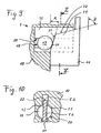
- FIGS. 9 and 10 an embodiment of a thread clamping device 8 is shown, in which the stroke of the sleeve 11 is greater than the diameter of the balls 19.
- two contact surfaces 21 and 22 are provided on the sleeve, which have a different angle A and B to the center line 23 of the spindle 1 have.
- the contact surfaces 21 and 22 are arranged on a radially inwardly projecting web 51.
- the web 51 protrudes into a recess 52 of the base body 10.
- the web 51 is arranged so that the ball 19 is centrally supported.
- the guide 20 for the ball 19 in the main body 10 is formed so that the ball 19 is guided by two segment-shaped guide surfaces 53 and in the radial direction from the illustrated first position to a second position similar to the illustration in FIG. 2 can move.
- the guide surfaces 53 are formed by cutouts of peripheral surfaces of a cylinder.
- the guide 20 and the contact surfaces 21, 22 arranged symmetrically to the ball center. The ball 19 is thereby guided very precisely, so that they do not jam in their radial movement.
- FIGS. 3 to 8 illustrated embodiments of the contact surfaces 21, 22 in one embodiment according to the FIGS. 9 and 10 deploy.
Description
Die Erfindung betrifft eine Fadenklemmeinrichtung für eine Spindel einer Spinn- oder Zwirnmaschine mit einer Aufnahme zur Anbringung der Fadenklemmeinrichtung an der Spindel, mit zwei gegeneinander beweglichen Klemmelementen zur Klemmung eines Fadens, mit wenigstens einem Belastungselement zum Schließen der Klemmelemente mit einer Belastungskraft, und mit wenigstens einem Entlastungselement zum Erzeugen einer der Belastungskraft entgegengerichteten Entlastungskraft, wobei das Entlastungselement in der Fadenklemmeinrichtung unter Fliehkrafteinwirkung bei rotierender Spindel beweglich ist und wobei die Klemmelemente durch die Entlastungskraft öffenbar sind.The invention relates to a thread clamping device for a spindle of a spinning or twisting machine with a receptacle for attaching the thread clamping device to the spindle, with two mutually movable clamping elements for clamping a thread, with at least one loading element for closing the clamping elements with a loading force, and at least one Relief element for generating a load force opposing the relieving force, wherein the relief element is movable in the thread clamping device under centrifugal force with rotating spindle and wherein the clamping elements can be opened by the unloading force.
Eine Fadenklemmeinrichtung dieser Art ist durch die
Die
Aus der
Da sich die Anziehungskraft der Magnete bei größer werdendem Klemmspalt reduziert, reduziert sich auch die Klemmkraft, je dicker der zu klemmende Faden ist. Gerade bei dickeren Fäden wird aufgrund einer höheren Reißfestigkeit des Fadens jedoch eine verstärkte Klemmkraft in der Fadenklemmeinrichtung gefordert. Außerdem sind Magnete teure Komponenten, insbesondere wenn sie wie im vorliegenden Fall eine hohe Magnetkraft aufweisen müssen und gleichzeitig unempfindlich gegen Vibrationen sein müssen.Since the attraction of the magnets reduces with increasing nip, the clamping force, the thicker the thread to be clamped is reduced. Especially with thicker threads, however, a stronger clamping force in the thread clamping device is required due to a higher tensile strength of the thread. In addition, magnets are expensive components, especially if they must have a high magnetic force as in the present case and at the same time must be insensitive to vibration.
Der Erfindung liegt die Aufgabe zugrunde, eine verbesserte Fadenklemmeinrichtung zu schaffen.The invention has for its object to provide an improved thread clamping device.
Die Aufgabe wird gemäß Anspruch 1 gelöst.The problem is solved according to
Dadurch dass bei einer definierten und konstant gehaltenen Spindeldrehzahl das Entlastungselement unterschiedlich große Entlastungskräfte ausüben kann, je nachdem, in welcher Position es sich befindet, lässt sich eine Fadenklemmeinrichtung schaffen, die sich bei einer ersten Spindeldrehzahl öffnet und bei einer zweiten, von der ersten verschiedenen Spindeldrehzahl schließt. Durch die veränderlichen Entlastungskräfte sind keine Magnete in der Fadenklemmeinrichtung erforderlich. Die Belastungskraft des wenigstens einen Belastungselementes kann im geöffneten Zustand der Klemmelemente höher als im geschlossenen Zustand der Klemmelemente sein. Hierdurch lässt sich der Vorteil erreichen, dass die Klemmkraft eines dickeren Fadens größer als die Klemmkraft eines dünneren Fadens ist. Während eines Kopswechselvorganges können so auch dicke Garne oder Zwirne sicher in der Fadenklemmeinrichtung gehalten werden. Trotzdem können alle Belastungselemente durch sehr preisgünstige Federelemente gebildet werden.Characterized that at a defined and kept constant spindle speed, the relief element can exert different levels of relief forces, depending on which position it is in a thread clamping device can create that opens at a first spindle speed and at a second, different from the first spindle speed closes. Due to the variable unloading forces no magnets in the thread clamping device are required. The loading force of the at least one loading element can be higher in the opened state of the clamping elements than in the closed state of the clamping elements. This makes it possible to achieve the advantage that the clamping force of a thicker thread is greater than the clamping force of a thinner thread. During a Kopswechselvorganges so thick yarns or threads can be held securely in the thread clamping device. Nevertheless, all load elements by very inexpensive spring elements be formed.
In vorteilhafter Ausgestaltung ist vorgesehen, dass einer ersten Position eines Entlastungselementes ein geschlossener Zustand der Klemmelemente und einer zweiten Position eines Entlastungselementes ein geöffneter Zustand der Klemmelemente zugeordnet ist, wobei vom Entlastungselement in der ersten Position bei geschlossenen Klemmelementen eine niedrige Entlastungskraft und in der zweiten Position bei geöffneten Klemmelementen eine hohe Entlastungskraft erzeugbar ist. Dieser Vergleich wird bei einer vorgegebenen und konstantgehaltenen Drehzahl der Spindel vorgenommen. Diese Ausgestaltung hat den Vorteil, dass sich die Klemmelemente in der Beschleunigungsphase der Spindel erst bei einer hohen Spindeldrehzahl öffnen und in der Verzögerungsphase bei einer niedrigen Spindeldrehzahl wieder schließen. Das Öffnen und Schließen der Fadenklemmeinrichtung geschieht, wenn sich die Entlastungskraft und die Belastungskraft im Gleichgewicht befinden. Dadurch dass das Entlastungselement zwei Positionen in der Fadenklemmeinrichtung einnehmen kann, in denen es unterschiedliche Entlastungskräfte erzeugt, gibt es zwei Grenzdrehzahlen, bei der Entlastungskraft und Belastungskraft im Gleichgewicht sind. Vorteilhafterweise ist bei Überschreiten einer oberen Grenzdrehzahl der Spindel ein Entlastungselement zum Öffnen der Klemmelemente von der ersten Position in die zweite Position bewegbar, und bei Unterschreiten einer unterhalb der oberen Grenzdrehzahl liegenden unteren Grenzdrehzahl ist ein Entlastungselement zum Schließen der Klemmelemente von der zweiten Position wieder in die erste Position bewegbar. Da vom Entlastungselement in der ersten Position nur eine niedrige Entlastungskraft bei einer vordefinierten Spindeldrehzahl erzeugbar ist, ist im Umkehrschluss eine höhere Spindeldrehzahl erforderlich, bis die Entlastungskraft ausreicht, die Belastungskraft aufzuheben und die Klemmelemente in den geöffneten Zustand zu bringen. In der Verzögerungsphase der Spindel befindet sich das Entlastungselement in der zweiten Position und erzeugt dementsprechend - bei gleicher Drehzahl - eine höhere Entlastungskraft. Die Spindeldrehzahl kann also bis zu der unteren Grenzdrehzahl gesenkt werden, ohne dass sich die Klemmelemente schließen. Erst bei Unterschreiten der unteren Grenzdrehzahl unterschreitet die Entlastungskraft die Belastungskraft, und führt zu einem Schließen der Klemmelemente.In an advantageous embodiment it is provided that a closed state of the clamping elements and a second position of a relief element is associated with an open state of the clamping elements a first position of a relief element, wherein the relief element in the first position with closed clamping elements a low unloading force and in the second position open clamping elements high discharge force can be generated. This comparison is made at a predetermined and kept constant speed of the spindle. This embodiment has the advantage that the clamping elements open in the acceleration phase of the spindle only at a high spindle speed and close again in the deceleration phase at a low spindle speed. The opening and closing of the thread clamping device happens when the unloading force and the loading force are in equilibrium. The fact that the relief element can take two positions in the thread clamping device, in which it generates different relief forces, there are two limit speeds, in which the unloading force and load force are in equilibrium. Advantageously, when an upper limit rotational speed of the spindle is exceeded, a relief element for opening the clamping elements from the first position to the second position movable, and falls below a lower limit than the lower limit speed is a relief element for closing the clamping elements of the second position back into the first position movable. Since only a low unloading force at a predefined spindle speed can be generated by the relief element in the first position, a higher spindle speed is required conversely until the unloading force is sufficient to release the loading force and bring the clamping elements into the open state. In the deceleration phase of the spindle, the relief element is in the second position and generates accordingly - at the same speed - a higher unloading force. The spindle speed can therefore be lowered to the lower limit speed without closing the clamping elements. Only when falling below the lower limit speed, the unloading force falls below the loading force, and leads to a closing of the clamping elements.
Zur Vermeidung von Unwuchten an der Spindel ist es vorteilhaft, mehrere Entlastungselemente am Umfang der Fadenklemmeinrichtung anzuordnen. Bevorzugt wird ein Entlastungselement durch einen im Wesentlichen radial beweglichen Fliehkraftkörper gebildet. Ein Fliehkraftkörper wird vorteilhafterweise durch eine Kugel gebildet.To avoid imbalances on the spindle, it is advantageous to arrange a plurality of relief elements on the circumference of the thread clamping device. Preferably, a relief element is formed by a substantially radially movable centrifugal force body. A centrifugal body is advantageously formed by a ball.
Dem Fliehkraftkörper sind wenigstens zwei Anlageflächen zugeordnet. Eine erste Anlagefläche ist der ersten Position des Fliehkraftkörpers und eine zweite Anlagefläche der zweiten Position des Fliehkraftkörpers zugeordnet. Dabei liegen die Anlageflächen auf einem unterschiedlichen Radius, der durch den Abstand der Anlagefläche zu der Mittellinie der Aufnahme zur Anbringung der Fadenklemmeinrichtung an der Spindel definiert wird. Da sich der Fliehkraftkörper von der ersten Position radial in die zweite Position bewegt und dabei die Klemmelemente öffnet, ist es vorteilhaft, die der ersten Position zugeordnete Anlagefläche auf einem kleineren Radius anzuordnen als die der zweiten Position zugeordnete Anlagefläche.The centrifugal body are assigned at least two contact surfaces. A first contact surface is associated with the first position of the centrifugal force body and a second contact surface with the second position of the centrifugal force body. The contact surfaces are at a different radius, which is defined by the distance of the contact surface to the center line of the receptacle for attaching the thread clamping device to the spindle. Since the centrifugal body moves radially from the first position to the second position and thereby opens the clamping elements, it is advantageous to arrange the contact surface assigned to the first position to a smaller radius than the contact surface assigned to the second position.
Erfindungsgemäß ist vorgesehen, dass eine im Berührpunkt zwischen einem Fliehkraftkörper und einer Anlagefläche angelegte Tangente - im Axialschnitt der Fadenklemmeinrichtung gesehen - einen Winkel zur Mittellinie der Aufnahme aufweist, und das an einer auf einem geringen Radius liegenden Anlagefläche eine Tangente vorhanden ist, die einen geringen Winkel zur Mittellinie der Aufnahme aufweist, und dass an einer auf einem großen Radius liegenden Anlagefläche eine Tangente vorhanden ist, die einen großen Winkel zur Mittellinie der Aufnahme aufweist. Der Winkel zwischen der Tangente und der Mittellinie bestimmt die Größe der Entlastungskraft bei gleicher Fliehkraft des Entlastungselementes. Durch diese Ausgestaltung lässt sich eine sehr einfache Fadenklemmeinrichtung schaffen, bei der von einem Entlastungselement bei einer definierbaren Spindeldrehzahl unterschiedliche Entlastungskräfte erzeugbar sind. In Abstimmung mit der Masse der Fliehkraftkörper lässt sich die obere und untere Grenzdrehzahl in sehr einfacher Weise durch die Geometrie der Anlageflächen an die Erfordernisse anpassen. Auf teure Magnete kann verzichtet werden. Auch ein zusätzlicher Montageschritt für die Anbringung der Magnete in der Fadenklemmeinrichtung kann entfallen. Eine erfindungsgemäße Fadenklemmeinrichtung lässt sich somit auch in großen Stückzahlen mit wenig Aufwand herstellen.According to the invention, a tangent applied at the contact point between a centrifugal force body and a contact surface, seen in the axial section of the thread clamping device, has an angle to the center line of the receptacle, and a tangent is present at a contact surface lying on a small radius, which has a small angle to the center line of the receptacle, and that at a lying on a large radius abutment surface a tangent is present, which has a large angle to the center line of the receptacle. The angle between the tangent and the center line determines the size of the unloading force with the same centrifugal force of the relief element. With this configuration, a very simple thread clamping device can be created in which different relief forces can be generated by a relief element at a definable spindle speed. In coordination with the mass of the centrifugal body, the upper and lower limit speed can be adapted in a very simple manner by the geometry of the contact surfaces to the requirements. On expensive magnets can be dispensed with. An additional assembly step for the attachment of the magnets in the thread clamping device can be omitted. An inventive thread clamping device can thus be produced in small quantities with little effort.
Es ist vorteilhaft, wenn die im Berührpunkt angelegte Tangente die Mittellinie schneidet. Besonders bevorzugt liegt die Tangente in der Axialschnitt-Ebene der Aufnahme. Hierdurch erfolgt eine besonders gute Umwandlung der durch den Fliehkraftkörper erzeugten Fliehkraft in eine der Belastungskraft entgegengerichtete Entlastungskraft. Der geringe Winkel beträgt zwischen 0° und 20° und liegt besonders bevorzugt im Bereich von 5° bis 10°. Der große Winkel beträgt vorteilhaft zwischen 60° und 80° und liegt besonders bevorzugt im Bereich von 60° bis 75°.It is advantageous if the tangent applied at the point of contact intersects the midline. Particularly preferably, the tangent lies in the axial section plane of the receptacle. This results in a particularly good conversion of the centrifugal force generated by the centrifugal force in one of the loading force opposing unloading force. The low angle is between 0 ° and 20 ° and is particularly preferably in the range of 5 ° to 10 °. The large angle is advantageously between 60 ° and 80 ° and is particularly preferably in the range of 60 ° to 75 °.
In weiterer Ausgestaltung kann es vorteilhaft sein, dass eine auf einem geringen Radius liegende Anlagefläche einen Bereich aufweist, der - im Axialschnitt gesehen - einen geringen Winkel mit der Mittellinie der Aufnahme einschließt. Eine auf einem großen Radius liegende Anlagefläche kann einen Bereich aufweisen der - im Axialschnitt gesehen - einen großen Winkel mit der Mittellinie der Aufnahme einschließt. Bereiche der Anlageflächen, die im Axialschnitt gradlinig verlaufen, lassen sich besonders einfach herstellen. Auch ist die vom Fliehkraftkörper erzeugte Entlastungskraft über den gradlinig verlaufenden Bereich der Anlagefläche im Wesentlichen konstant, so dass der Einfluss von Fertigungstoleranzen auf die obere und untere Grenzdrehzahl verringert werden kann. Bei einer in einem Bereich gradlinig verlaufenden Anlagefläche entspricht der Winkel zwischen Anlagefläche und Mittellinie genau dem Winkel zwischen der Mittellinie und einer im Berührpunkt des Fliehkraftkörpers an der Anlagefläche angelegten Tangente.In a further embodiment, it may be advantageous for a contact surface lying on a small radius to have a region which, viewed in axial section, encloses a small angle with the center line of the receptacle. A contact surface lying on a large radius can have a region which, viewed in axial section, encloses a large angle with the center line of the receptacle. Areas of the contact surfaces that run straight in axial section leave make it very easy. Also, the unloading force generated by the centrifugal body is substantially constant over the rectilinear region of the contact surface, so that the influence of manufacturing tolerances on the upper and lower limit speed can be reduced. In an area extending in a straight line contact surface, the angle between the contact surface and center line corresponds exactly to the angle between the center line and a tangent applied to the contact surface of the centrifugal body tangent.
Um eine reibungslose Bewegung des Fliehkraftkörpers in radialer Richtung zu gewährleisten, kann es vorteilhaft sein, dass zwischen der auf einem geringen Radius liegenden Anlagefläche und der auf einem großen Radius liegenden Anlagefläche eine Anlagefläche vorhanden ist, deren Winkel zu der Mittellinie sich mit zunehmendem Radius stetig vergrößert.In order to ensure a smooth movement of the centrifugal body in the radial direction, it may be advantageous that between the lying on a small radius contact surface and lying on a large radius contact surface, a contact surface is present whose angle to the center line increases steadily with increasing radius ,
Es kann vorteilhaft sein, dass eine Anlagefläche für einen Fliehkraftkörper an einer durch Fliehkrafteinwirkung verformbaren Komponente der Fadenklemmeinrichtung angeordnet ist. Der Fliehkraftkörper und die durch Fliehkrafteinwirkung verformbare Komponente weisen einen Berührpunkt auf, in dem eine Tangente anlegbar ist. Diese Ausgestaltung hat den Vorteil, dass sich der Winkel der Tangente zur Mittelachse der Aufnahme während der Beschleunigungsphase der Spindel verändert. Bei niedrigen Spindeldrehzahlen ist der Winkel der Tangente zur Mittelinie sehr klein, so dass durch die Zusatzkomponente eine hohe obere Grenzdrehzahl erreichbar ist, bei der sich die Klemmelemente öffnen. Die durch Fliehkrafteinwirkung verformbare Komponente ist dabei bevorzugt durch einen Ring gebildet. Der Mittelpunkt des Rings liegt bevorzugt auf der Mittellinie der Aufnahme. Der Ring kann vorteilhaft aus einem gummielastischen Material bestehen. Der Ring ist bevorzugt so angeordnet, dass er die Bewegung des Fliehkraftkörpers beim Schließen der Klemmelemente nicht behindert.It may be advantageous that a contact surface for a centrifugal body is arranged on a deformable by centrifugal force component of the thread clamping device. The centrifugal body and the deformable by centrifugal force component have a contact point in which a tangent can be applied. This embodiment has the advantage that the angle of the tangent to the central axis of the recording changes during the acceleration phase of the spindle. At low spindle speeds, the angle of the tangent to the center line is very small, so that a high upper limit speed is reached by the additional component, in which open the clamping elements. The deformable by centrifugal force component is preferably formed by a ring. The center of the ring is preferably on the center line of the receptacle. The ring may advantageously consist of a rubber-elastic material. The ring is preferably arranged so that it does not hinder the movement of the centrifugal body when closing the clamping elements.
Weitere Vorteile und Merkmale der Erfindung ergeben sich aus der nachfolgenden Beschreibung einiger Ausführungsbeispiele.Further advantages and features of the invention will become apparent from the following description of some embodiments.
Es zeigen:
-
Figur 1 -
Figur 2Spindel aus Figur 1 mit geöffneter Fadenklemmeinrichtung, -
Figur 3 den mit III gekennzeichneten Bereich der Figur 1 in vergrößerter Darstellung, -
Figuren 4bis 8Figur 3 bei anders ausgestalteten Fadenklemmeinrichtungen, -
Figur 9Figur 3 auf eine abgewandelte Ausgestaltung einer Fadenklemmeinrichtung, -
Figur 10Figur 9 geschnittene Ansicht.
-
FIG. 1 a partially sectioned axial view of an enlarged illustrated spindle, with a closed thread clamping device, -
FIG. 2 the same spindleFIG. 1 with opened thread clamping device, -
FIG. 3 the area marked III in FIG. 1 in an enlarged view, -
FIGS. 4 to 8 Similar viewsFIG. 3 in differently configured thread clamping devices, -
FIG. 9 a view similarFIG. 3 to a modified embodiment of a thread clamping device, -
FIG. 10 one along the section XX of theFIG. 9 cut view.
In
Oberhalb des Wirtels 6 ist eine Fadenklemmeinrichtung 8 angeordnet. Die Fadenklemmeinrichtung 8 ist mit einer Aufnahme 9 an dem Spindeloberteil 2 angebracht. Die Fadenklemmeinrichtung 8 ist bevorzugt lösbar am Oberteil 2 befestigt, um im Falle eines Defektes leicht austauschbar zu sein. Das Oberteil 2 kann oberhalb der Fadenklemmeinrichtung 8 eine nicht dargestellte Spulenhülse aufnehmen, auf welcher der erzeugte Faden zu einer Spule aufgewunden wird. Der Aufwindevorgang wird bekannter Weise mittels einer heb- und senkbaren Ringbank durchgeführt, die sich über eine Vielzahl von nebeneinander in der Maschine angeordneten Spindeln 1 erstreckt. Jeder Spindel 1 ist ein ebenfalls nicht dargestellter Spinnring zugeordnet, auf dem in bekannter Weise ein Läufer umläuft, der bei Betrieb dem Faden eine Drehung erteilt und ihn auf die Spule führt.Above the whorl 6 a
Die Fadenklemmeinrichtung 8 besteht aus einem hülsenförmigen Grundkörper 10, der die Aufnahme 9 für die Spindel 1 enthält. Auf dem Grundkörper 10 ist eine axial verschiebbare Hülse 11 angeordnet. Am Grundkörper 10 und an der Hülse 11 ist jeweils ein Klemmelement 12 und 13 angeordnet. Die Klemmelemente 12 und 13 enthalten Klemmflächen 14 und 15, die einen Spalt 16 zur Klemmung eines Fadens bilden können. Der zu klemmende Faden wird auch als "Unterwindefaden" bezeichnet. Der geöffnete Spalt 16 zwischen den Klemmelementen 12 und 13 ist in
Die Bewegung der Hülse 11 beim Öffnen und Schließen der Klemmelemente 12, 13 wird durch zwei Führungen 41 und 42 gewährleistet. Damit die Hülse 11 präzise auf dem Grundkörper 10 geführt ist, ist eine erste Führung im Bereich des Klemmelementes 13 angeordnet. Eine zweite Führung 42 ist möglichst weit von der ersten Führung 41 beabstandet. Die Führung 41 und die Führung 42 sind so angeordnet, dass sich das Belastungselement 17 und die Entlastungselemente 18 im Axialschnitt gesehen zwischen den beiden Führungen 41, 42 befinden. Zur Minimierung von unerwünschten Unwuchten an der Fadenklemmeinrichtung 8 ist die Feder 17 durch den Grundkörper 10 geführt und zentriert.The movement of the
Die Fadenklemmeinrichtung 8 enthält außerdem mehrere Entlastungselemente 18 zum Erzeugen einer der Belastungskraft entgegengerichteten Entlastungskraft. In den
In dem in
Der Zustand der Fadenklemmeinrichtung 8 mit geöffneten Klemmelementen 12, 13 ist in
In
Zur Verdeutlichung wird der Ablauf beim Betrieb einer Spindel 1 mit einer erfindungsgemäßen Fadenklemmeinrichtung 8 noch einmal chronologisch beschrieben. Während des Spinn- oder Zwirnvorgangs mit Betriebsdrehzahl, die beispielsweise 20.000 1/min beträgt, ist die Fadenklemmeinrichtung 8 geöffnet. Der Spalt 16 ist leer. Der Faden wird auf die Hülse aufgewunden, die sich auf den Oberteil 2 der Spindel 1 befindet. Vor einem Kopswechsel-Vorgang, bei dem die volle Spule bzw. der volle Kops gegen eine leere Hülse ausgetauscht wird, wird die Ringbank mit dem Ring in eine Position gefahren, dass sich der Faden in den Spalt 16 einlegt. Bei diesem sogenannten Unterwindevorgang des Fadens wird die Drehzahl der Spindel 1 reduziert. Wenn die Spindeldrehzahl den unteren Grenzwert unterschreitet, schließt sich die Fadenklemmeinrichtung 8 und der Unterwindefaden wird zwischen den Klemmelementen 12 und 13 geklemmt. Anschließend wird die Spindel angehalten und der volle Kops wird nach oben vom Oberteil 2 abgezogen. Das vom Streck- oder Lieferwerk kommende Fadenende bleibt beim Abziehen des vollen Kopses in der Fadenklemmeinrichtung 8 geklemmt und der Faden wird zwischen Kops und Fadenklemmeinrichtung 8 getrennt. Nach dem Aufsetzen einer leeren Hülse auf das Oberteil 2 wird die Maschine wieder angefahren. Während des Beschleunigens der Spindel 1 wird die Ringbank bereits wieder in eine Position hochgefahren, so dass der Faden auf die auf dem Oberteil 2 sitzende Hülse aufgewickelt wird. Überschreitet die Spindeldrehzahl einen oberen Grenzwert, öffnet sich die Fadenklemmeinrichtung 8 wieder und das im Spalt 16 geklemmte Fadenende wird herausgeschleudert. Um einen sicheren und zuverlässigen Betrieb während eines Kopswechsel-Vorgangs sicherzustellen, ist es vorteilhaft, wenn die untere Grenzdrehzahl sehr niedrig liegt, beispielsweise in der Größenordnung von etwa 1.000 bis 2.000 1/min. Beim Einlegen des Unterwindefadens in den Spalt 16 ist es wichtig, dass der Faden zum einen sicher im Spalt 16 liegt, um zuverlässig geklemmt werden zu können, aber andererseits darf der Faden den Grundkörper 10 der Fadenklemmeinrichtung nicht mehr als 360° umschlingen, damit sich das Fadenende später auch wieder leicht aus den Klemmelementen 12 und 13 herauslöst. Ein Einlegen des Unterwindefadens in den Spalt 16 lässt sich präziser und einfacher realisieren, wenn die Spindeldrehzahl möglichst gering ist. Deshalb ist es wichtig, dass die Fadenklemmeinrichtung 8 bei möglichst geringer unterer Grenzdrehzahl schließt. Im Gegensatz dazu ist es in der Beschleunigungsphase der Spindel sehr vorteilhaft, wenn die obere Grenzdrehzahl, bei der sich die Fadenklemmeinrichtung 8 wieder öffnet, bei einer möglichst hohen Spindeldrehzahl, beispielsweise in der Größenordnung von 10.000 1/min, befindet. Das zwischen den Klemmelementen 12 und 13 eingeklemmte Ende des Unterwindefadens wird dadurch so lange sicher in der Fadenklemmeinrichtung 8 gehalten, bis genügend Windungen auf der leeren Hülse aufgewunden sind. Fehlfunktionen und Fadenbrüche beim Kopswechsel lassen sich so sehr stark verringern.To clarify the sequence when operating a
Zur weiteren Optimierung der Fadenklemmeinrichtung 8 lässt sich die Gestaltung der Anlageflächen 21 und 22 variieren. In den
Bei der Variante in
In
Da die Auflageflächen 21 und 22 in den
In
In
Bei den in den
In den
Selbstverständlich lassen sich auch die in den
Claims (12)
- Yarn nipping device for a spindle (1) of a spinning or twisting machine comprising a receptacle (9) for mounting the yarn nipping device (8) on the spindle (1), comprising two nipping elements (12, 13) movable in opposite directions to one another for nipping a yarn, also comprising at least one loading element (17) for closing the nipping elements by means of a loading force, also comprising at least one load-relieving element (18) for generating a relieving force which acts in opposite direction to the direction of the loading force, wherein the at least one load-relieving element (18) is movable in the yarn nipping device under centrifugal force when the spindle (1) is rotating, wherein the nipping elements (12, 13) can be opened by means of the load-relieving force, wherein at least two positions are assigned to at least one load-relieving element (18) in the yarn nipping device (8) and at a definable spindle speed different load-relieving forces are generable by the load-relieving element (18) depending on said position, wherein a load-relieving element (18) is formed by an essentially radially movable centrifugal force body (19), wherein at least two supporting surfaces (21, 22) are assigned to the centrifugal force body (19), wherein the supporting surfaces (21, 22) lie on different radii, which are formed by the distance of the supporting surface (21; 22) to the centre line (23) of the receptacle (9) for mounting the yarn nipping device (8) on the spindle (1), wherein a tangent (27; 28) drawn in a contact point (24) between a centrifugal force body (19) and a supporting surface (21; 22) - as seen in axial section of the yarn nipping device (8) - forms an angle (A; B) in relation to the centre line (23) of the receptacle (9), wherein a tangent (27) is formed on a supporting surface (21) lying on a lesser radius, said tangent (27) forming a small angle (A) in relation to the centre line (23) of the receptacle (9) and wherein a tangent (28) is formed on a supporting surface (22) lying on a larger radius, which tangent (28) forms a large angle (B) in relation to the centre line (23) of the receptacle (8) characterized in that the small angle (A) is between 0° and 20°.
- Yarn nipping device according to claim 1, wherein a closed state of the nipping elements (12, 13) is assigned to a first position of a load-relieving element (18), and an opened state of the nipping elements (12, 13) is assigned to a second position of a load-relieving element (18), whereby the load-relieving element (18) can generate a low level of load-relieving force in the first position when the nipping elements (12, 13) are closed, and can generate a high level of load-relieving force in the second position when the nipping elements (12, 13) are open.
- Yarn nipping device according to claim 1 or 2, wherein the loading force of the at least one loading element (17) is greater in the open state of the nipping elements (12, 13) than in the closed state of the nipping elements (12, 13).
- Yarn nipping device according to claim 3, wherein all loading elements (17) take the form of spring elements.
- Yarn nipping device according to any one of the claims 1 to 4, wherein when an upper threshold speed of the spindle (1) is exceeded, a load-relieving element (18) for opening the nipping elements (12, 13) is movable from the first position into the second position, and wherein when the threshold speed falls below a low threshold lower than the upper threshold speed, a load-relieving element (18) for closing the nipping elements (12, 13) is movable from the second position into the first position.
- Yarn nipping device according to any one of the claims 1 to 5, wherein a number of load-relieving elements (18) are arranged on the circumference of the yarn nipping device (8).
- Yarn nipping device according to any one of the claims 1 to 6, wherein the centrifugal force body being preferably formed by a ball (19).
- Yarn nipping device according to claim 1, wherein a supporting surface (21) lying on a lesser radius comprises an area which, as seen in axial section, encompasses a small angle (A) in relation to the centre line (23) of the receptacle (9).
- Yarn nipping device according to claim 1 or 8, wherein a supporting surface (22) lying on a larger radius comprises an area which, as seen in axial section, forms a large angle (B) with the centre line (23) of the receptacle (9).
- Yarn nipping device according to any one of the claims 8 or 9, wherein between the supporting surface (21) lying on a lesser radius and the supporting surface (22) lying on a larger radius, a supporting surface 26 exists whose angle in relation to the centre line (23) of the receptacle (9) increases consistently with increasing radius.
- Yarn nipping device according to any one of the claims 1, 8, 9 or 10, wherein a supporting surface (21) for a centrifugal force body (19) is assigned to a component (29) of the yarn nipping device (8), said component (29) being deformable by centrifugal force action.
- Yarn nipping device according to claim 11, wherein the component (29) which is deformable by centrifugal force action takes the form of a ring (30) the ring (30) is being preferably made of a flexible rubber material.
Applications Claiming Priority (1)
| Application Number | Priority Date | Filing Date | Title |
|---|---|---|---|
| DE200910023644 DE102009023644A1 (en) | 2009-05-25 | 2009-05-25 | Thread clamping device for a spindle of a spinning or twisting machine |
Publications (3)
| Publication Number | Publication Date |
|---|---|
| EP2256238A1 EP2256238A1 (en) | 2010-12-01 |
| EP2256238B1 EP2256238B1 (en) | 2014-05-07 |
| EP2256238B2 true EP2256238B2 (en) | 2018-11-14 |
Family
ID=42651398
Family Applications (1)
| Application Number | Title | Priority Date | Filing Date |
|---|---|---|---|
| EP10004384.3A Active EP2256238B2 (en) | 2009-05-25 | 2010-04-26 | Thread trapper device for a spindle of a spinning or thread machine |
Country Status (4)
| Country | Link |
|---|---|
| EP (1) | EP2256238B2 (en) |
| JP (1) | JP2010270430A (en) |
| CN (1) | CN101899730B (en) |
| DE (1) | DE102009023644A1 (en) |
Families Citing this family (6)
| Publication number | Priority date | Publication date | Assignee | Title |
|---|---|---|---|---|
| DE102008058655B4 (en) * | 2008-11-22 | 2019-01-10 | Saurer Spinning Solutions Gmbh & Co. Kg | clamping device |
| DE102011076744A1 (en) * | 2011-05-31 | 2012-12-06 | Maschinenfabrik Rieter Ag | Thread clamping device for a spinning or twisting spindle |
| DE102013020470A1 (en) * | 2013-12-03 | 2015-06-03 | Saurer Components Gmbh | Clamping device for clamping a thread on a spindle of a spinning or twisting machine and spinning or twisting machine |
| CN108138385B (en) * | 2015-11-06 | 2020-12-04 | Ate私有企业有限责任公司 | Clamping device in winding and method for clamping yarn |
| DE102017103754A1 (en) * | 2017-02-23 | 2018-08-23 | Maschinenfabrik Rieter Ag | Clamping device, spindle with a clamping device and method for producing a clamping device |
| CN111676555A (en) * | 2020-06-08 | 2020-09-18 | 山东祥瑞祥纺织有限公司 | Application of variable count in automatic doffing link of yarn with density of more than 59tex |
Family Cites Families (9)
| Publication number | Priority date | Publication date | Assignee | Title |
|---|---|---|---|---|
| JPH0315562Y2 (en) * | 1988-08-31 | 1991-04-04 | ||
| DE19628826A1 (en) | 1996-07-17 | 1998-01-22 | Lieser Gmbh Beteiligungsgesell | Clamp unit for yarns for spindles |
| JPH10140427A (en) * | 1996-11-05 | 1998-05-26 | Howa Mach Ltd | Method for stopping ring spinning frame and ring spinning frame |
| IT1299011B1 (en) * | 1997-06-06 | 2000-02-07 | Novibra Gmbh | SPINDLE FOR A RENDER OR RING MACHINE |
| DE19746819A1 (en) * | 1997-10-23 | 1999-04-29 | Novibra Gmbh | Control of under-winding of waste on self-cleaning ring spindle |
| JP2001316948A (en) * | 2000-05-11 | 2001-11-16 | Howa Mach Ltd | Method for stopping ring spinning loom and ring spinning loom |
| DE102005061043A1 (en) * | 2005-12-08 | 2007-06-14 | König, Günter | Thread clamping device for underwinding threads on spindles of a ring spinning or ring twisting machine |
| DE102006022484B4 (en) * | 2006-05-13 | 2017-04-27 | Saurer Components Gmbh | clamping device |
| DE102008058655B4 (en) * | 2008-11-22 | 2019-01-10 | Saurer Spinning Solutions Gmbh & Co. Kg | clamping device |
-
2009
- 2009-05-25 DE DE200910023644 patent/DE102009023644A1/en not_active Withdrawn
-
2010
- 2010-04-26 EP EP10004384.3A patent/EP2256238B2/en active Active
- 2010-05-19 JP JP2010114891A patent/JP2010270430A/en active Pending
- 2010-05-25 CN CN201010189342.4A patent/CN101899730B/en active Active
Also Published As
| Publication number | Publication date |
|---|---|
| CN101899730A (en) | 2010-12-01 |
| EP2256238A1 (en) | 2010-12-01 |
| DE102009023644A1 (en) | 2010-12-02 |
| EP2256238B1 (en) | 2014-05-07 |
| CN101899730B (en) | 2015-06-24 |
| JP2010270430A (en) | 2010-12-02 |
Similar Documents
| Publication | Publication Date | Title |
|---|---|---|
| EP2256238B2 (en) | Thread trapper device for a spindle of a spinning or thread machine | |
| EP2189408B1 (en) | Clamping device | |
| EP2024265B1 (en) | Clamping device | |
| EP2530041B1 (en) | Yarn nipping device for a spinning or twisting spindle | |
| EP2881351A1 (en) | Clamping device for clamping a thread on a spindle of a spinning or twisting machine, and spinning or twisting machine | |
| WO2005115896A1 (en) | Winding machine | |
| DE7331545U (en) | DEVICE FOR TRANSFERRING THREADS IN RING SPINNING MACHINES | |
| CH706759A1 (en) | Shielding element for spindle to retain thread fastened at spindle rail of spinning machine to spin e.g. thread, has drive element connected with shaft, and recess provided at end turned away to ring rail over portion of circumference | |
| EP3260406B1 (en) | Thread clamping device | |
| EP1957697A2 (en) | Thread clamping device for lower winding threads on spindles of a ring spinning frame or ring twisting frame | |
| EP2157217B1 (en) | Clamping device | |
| EP0775769A1 (en) | Device for clamping an underwinding yarn at a spindle of a spinning or twisting machine | |
| DE19705872A1 (en) | Ring spinner yarn balloon limit | |
| DE3025470A1 (en) | OPEN-END SPIDING METHOD AND DEVICE FOR CARRYING OUT THIS METHOD | |
| WO2022008724A1 (en) | Method and apparatus for introducing a false twist, and spinning machine | |
| DE741581C (en) | Spindle for spinning and twisting machines | |
| DE4206030C2 (en) | Centrifuge spinning device with means for piecing | |
| DE2653697C2 (en) | Device for ring spinning or ring twisting | |
| EP0458088A1 (en) | Yarn severing device for a spindle of a spinning or twisting machine | |
| DE4021272C2 (en) | Double-wire twisting spindle with a thread brake arranged above the thread storage disc in the area of the hollow spindle axis | |
| DE1760458A1 (en) | Process for severing threads underneath spindles and spindle for carrying out the process | |
| EP3029185A1 (en) | Multi-thread yarn spindle for yarn twisting machine | |
| DE19820211C1 (en) | Bobbin yarn underwinding clamp | |
| CH692663A5 (en) | Spindle for a spinning or ring twisting machine. | |
| DE3732967C2 (en) |
Legal Events
| Date | Code | Title | Description |
|---|---|---|---|
| PUAI | Public reference made under article 153(3) epc to a published international application that has entered the european phase |
Free format text: ORIGINAL CODE: 0009012 |
|
| AK | Designated contracting states |
Kind code of ref document: A1 Designated state(s): AT BE BG CH CY CZ DE DK EE ES FI FR GB GR HR HU IE IS IT LI LT LU LV MC MK MT NL NO PL PT RO SE SI SK SM TR |
|
| AX | Request for extension of the european patent |
Extension state: AL BA ME RS |
|
| 17P | Request for examination filed |
Effective date: 20110218 |
|
| 17Q | First examination report despatched |
Effective date: 20111102 |
|
| GRAP | Despatch of communication of intention to grant a patent |
Free format text: ORIGINAL CODE: EPIDOSNIGR1 |
|
| INTG | Intention to grant announced |
Effective date: 20131206 |
|
| GRAS | Grant fee paid |
Free format text: ORIGINAL CODE: EPIDOSNIGR3 |
|
| GRAA | (expected) grant |
Free format text: ORIGINAL CODE: 0009210 |
|
| AK | Designated contracting states |
Kind code of ref document: B1 Designated state(s): AT BE BG CH CY CZ DE DK EE ES FI FR GB GR HR HU IE IS IT LI LT LU LV MC MK MT NL NO PL PT RO SE SI SK SM TR |
|
| REG | Reference to a national code |
Ref country code: GB Ref legal event code: FG4D Free format text: NOT ENGLISH |
|
| REG | Reference to a national code |
Ref country code: AT Ref legal event code: REF Ref document number: 666790 Country of ref document: AT Kind code of ref document: T Effective date: 20140515 |
|
| REG | Reference to a national code |
Ref country code: IE Ref legal event code: FG4D Free format text: LANGUAGE OF EP DOCUMENT: GERMAN |
|
| REG | Reference to a national code |
Ref country code: DE Ref legal event code: R096 Ref document number: 502010006850 Country of ref document: DE Effective date: 20140618 |
|
| REG | Reference to a national code |
Ref country code: NL Ref legal event code: VDEP Effective date: 20140507 |
|
| REG | Reference to a national code |
Ref country code: LT Ref legal event code: MG4D |
|
| PG25 | Lapsed in a contracting state [announced via postgrant information from national office to epo] |
Ref country code: LT Free format text: LAPSE BECAUSE OF FAILURE TO SUBMIT A TRANSLATION OF THE DESCRIPTION OR TO PAY THE FEE WITHIN THE PRESCRIBED TIME-LIMIT Effective date: 20140507 Ref country code: NO Free format text: LAPSE BECAUSE OF FAILURE TO SUBMIT A TRANSLATION OF THE DESCRIPTION OR TO PAY THE FEE WITHIN THE PRESCRIBED TIME-LIMIT Effective date: 20140807 Ref country code: IS Free format text: LAPSE BECAUSE OF FAILURE TO SUBMIT A TRANSLATION OF THE DESCRIPTION OR TO PAY THE FEE WITHIN THE PRESCRIBED TIME-LIMIT Effective date: 20140907 Ref country code: CY Free format text: LAPSE BECAUSE OF FAILURE TO SUBMIT A TRANSLATION OF THE DESCRIPTION OR TO PAY THE FEE WITHIN THE PRESCRIBED TIME-LIMIT Effective date: 20140507 Ref country code: FI Free format text: LAPSE BECAUSE OF FAILURE TO SUBMIT A TRANSLATION OF THE DESCRIPTION OR TO PAY THE FEE WITHIN THE PRESCRIBED TIME-LIMIT Effective date: 20140507 Ref country code: GR Free format text: LAPSE BECAUSE OF FAILURE TO SUBMIT A TRANSLATION OF THE DESCRIPTION OR TO PAY THE FEE WITHIN THE PRESCRIBED TIME-LIMIT Effective date: 20140808 |
|
| PG25 | Lapsed in a contracting state [announced via postgrant information from national office to epo] |
Ref country code: HR Free format text: LAPSE BECAUSE OF FAILURE TO SUBMIT A TRANSLATION OF THE DESCRIPTION OR TO PAY THE FEE WITHIN THE PRESCRIBED TIME-LIMIT Effective date: 20140507 Ref country code: ES Free format text: LAPSE BECAUSE OF FAILURE TO SUBMIT A TRANSLATION OF THE DESCRIPTION OR TO PAY THE FEE WITHIN THE PRESCRIBED TIME-LIMIT Effective date: 20140507 Ref country code: SE Free format text: LAPSE BECAUSE OF FAILURE TO SUBMIT A TRANSLATION OF THE DESCRIPTION OR TO PAY THE FEE WITHIN THE PRESCRIBED TIME-LIMIT Effective date: 20140507 Ref country code: LV Free format text: LAPSE BECAUSE OF FAILURE TO SUBMIT A TRANSLATION OF THE DESCRIPTION OR TO PAY THE FEE WITHIN THE PRESCRIBED TIME-LIMIT Effective date: 20140507 Ref country code: PL Free format text: LAPSE BECAUSE OF FAILURE TO SUBMIT A TRANSLATION OF THE DESCRIPTION OR TO PAY THE FEE WITHIN THE PRESCRIBED TIME-LIMIT Effective date: 20140507 |
|
| PG25 | Lapsed in a contracting state [announced via postgrant information from national office to epo] |
Ref country code: PT Free format text: LAPSE BECAUSE OF FAILURE TO SUBMIT A TRANSLATION OF THE DESCRIPTION OR TO PAY THE FEE WITHIN THE PRESCRIBED TIME-LIMIT Effective date: 20140908 |
|
| PG25 | Lapsed in a contracting state [announced via postgrant information from national office to epo] |
Ref country code: DK Free format text: LAPSE BECAUSE OF FAILURE TO SUBMIT A TRANSLATION OF THE DESCRIPTION OR TO PAY THE FEE WITHIN THE PRESCRIBED TIME-LIMIT Effective date: 20140507 Ref country code: EE Free format text: LAPSE BECAUSE OF FAILURE TO SUBMIT A TRANSLATION OF THE DESCRIPTION OR TO PAY THE FEE WITHIN THE PRESCRIBED TIME-LIMIT Effective date: 20140507 Ref country code: SK Free format text: LAPSE BECAUSE OF FAILURE TO SUBMIT A TRANSLATION OF THE DESCRIPTION OR TO PAY THE FEE WITHIN THE PRESCRIBED TIME-LIMIT Effective date: 20140507 Ref country code: RO Free format text: LAPSE BECAUSE OF FAILURE TO SUBMIT A TRANSLATION OF THE DESCRIPTION OR TO PAY THE FEE WITHIN THE PRESCRIBED TIME-LIMIT Effective date: 20140507 |
|
| REG | Reference to a national code |
Ref country code: DE Ref legal event code: R026 Ref document number: 502010006850 Country of ref document: DE |
|
| PLBI | Opposition filed |
Free format text: ORIGINAL CODE: 0009260 |
|
| PG25 | Lapsed in a contracting state [announced via postgrant information from national office to epo] |
Ref country code: NL Free format text: LAPSE BECAUSE OF FAILURE TO SUBMIT A TRANSLATION OF THE DESCRIPTION OR TO PAY THE FEE WITHIN THE PRESCRIBED TIME-LIMIT Effective date: 20140507 |
|
| 26 | Opposition filed |
Opponent name: SAURER COMPONENTS GMBH Effective date: 20150131 |
|
| PLAX | Notice of opposition and request to file observation + time limit sent |
Free format text: ORIGINAL CODE: EPIDOSNOBS2 |
|
| REG | Reference to a national code |
Ref country code: DE Ref legal event code: R026 Ref document number: 502010006850 Country of ref document: DE Effective date: 20150131 |
|
| PLBB | Reply of patent proprietor to notice(s) of opposition received |
Free format text: ORIGINAL CODE: EPIDOSNOBS3 |
|
| PLAS | Information related to reply of patent proprietor to notice(s) of opposition deleted |
Free format text: ORIGINAL CODE: EPIDOSDOBS3 |
|
| PLBB | Reply of patent proprietor to notice(s) of opposition received |
Free format text: ORIGINAL CODE: EPIDOSNOBS3 |
|
| PG25 | Lapsed in a contracting state [announced via postgrant information from national office to epo] |
Ref country code: SI Free format text: LAPSE BECAUSE OF FAILURE TO SUBMIT A TRANSLATION OF THE DESCRIPTION OR TO PAY THE FEE WITHIN THE PRESCRIBED TIME-LIMIT Effective date: 20140507 |
|
| PG25 | Lapsed in a contracting state [announced via postgrant information from national office to epo] |
Ref country code: LU Free format text: LAPSE BECAUSE OF FAILURE TO SUBMIT A TRANSLATION OF THE DESCRIPTION OR TO PAY THE FEE WITHIN THE PRESCRIBED TIME-LIMIT Effective date: 20150426 Ref country code: MC Free format text: LAPSE BECAUSE OF FAILURE TO SUBMIT A TRANSLATION OF THE DESCRIPTION OR TO PAY THE FEE WITHIN THE PRESCRIBED TIME-LIMIT Effective date: 20140507 |
|
| GBPC | Gb: european patent ceased through non-payment of renewal fee |
Effective date: 20150426 |
|
| REG | Reference to a national code |
Ref country code: IE Ref legal event code: MM4A |
|
| PG25 | Lapsed in a contracting state [announced via postgrant information from national office to epo] |
Ref country code: GB Free format text: LAPSE BECAUSE OF NON-PAYMENT OF DUE FEES Effective date: 20150426 |
|
| REG | Reference to a national code |
Ref country code: FR Ref legal event code: ST Effective date: 20151231 |
|
| PG25 | Lapsed in a contracting state [announced via postgrant information from national office to epo] |
Ref country code: FR Free format text: LAPSE BECAUSE OF NON-PAYMENT OF DUE FEES Effective date: 20150430 |
|
| PG25 | Lapsed in a contracting state [announced via postgrant information from national office to epo] |
Ref country code: IE Free format text: LAPSE BECAUSE OF NON-PAYMENT OF DUE FEES Effective date: 20150426 |
|
| REG | Reference to a national code |
Ref country code: AT Ref legal event code: MM01 Ref document number: 666790 Country of ref document: AT Kind code of ref document: T Effective date: 20150426 |
|
| PLAB | Opposition data, opponent's data or that of the opponent's representative modified |
Free format text: ORIGINAL CODE: 0009299OPPO |
|
| PG25 | Lapsed in a contracting state [announced via postgrant information from national office to epo] |
Ref country code: AT Free format text: LAPSE BECAUSE OF NON-PAYMENT OF DUE FEES Effective date: 20150426 |
|
| R26 | Opposition filed (corrected) |
Opponent name: SAURER COMPONENTS GMBH Effective date: 20150131 |
|
| PG25 | Lapsed in a contracting state [announced via postgrant information from national office to epo] |
Ref country code: MT Free format text: LAPSE BECAUSE OF FAILURE TO SUBMIT A TRANSLATION OF THE DESCRIPTION OR TO PAY THE FEE WITHIN THE PRESCRIBED TIME-LIMIT Effective date: 20140507 |
|
| PG25 | Lapsed in a contracting state [announced via postgrant information from national office to epo] |
Ref country code: BG Free format text: LAPSE BECAUSE OF FAILURE TO SUBMIT A TRANSLATION OF THE DESCRIPTION OR TO PAY THE FEE WITHIN THE PRESCRIBED TIME-LIMIT Effective date: 20140507 Ref country code: SM Free format text: LAPSE BECAUSE OF FAILURE TO SUBMIT A TRANSLATION OF THE DESCRIPTION OR TO PAY THE FEE WITHIN THE PRESCRIBED TIME-LIMIT Effective date: 20140507 Ref country code: HU Free format text: LAPSE BECAUSE OF FAILURE TO SUBMIT A TRANSLATION OF THE DESCRIPTION OR TO PAY THE FEE WITHIN THE PRESCRIBED TIME-LIMIT; INVALID AB INITIO Effective date: 20100426 |
|
| PG25 | Lapsed in a contracting state [announced via postgrant information from national office to epo] |
Ref country code: BE Free format text: LAPSE BECAUSE OF NON-PAYMENT OF DUE FEES Effective date: 20150430 |
|
| PG25 | Lapsed in a contracting state [announced via postgrant information from national office to epo] |
Ref country code: MK Free format text: LAPSE BECAUSE OF FAILURE TO SUBMIT A TRANSLATION OF THE DESCRIPTION OR TO PAY THE FEE WITHIN THE PRESCRIBED TIME-LIMIT Effective date: 20140507 |
|
| PUAH | Patent maintained in amended form |
Free format text: ORIGINAL CODE: 0009272 |
|
| STAA | Information on the status of an ep patent application or granted ep patent |
Free format text: STATUS: PATENT MAINTAINED AS AMENDED |
|
| REG | Reference to a national code |
Ref country code: CH Ref legal event code: AELC |
|
| 27A | Patent maintained in amended form |
Effective date: 20181114 |
|
| AK | Designated contracting states |
Kind code of ref document: B2 Designated state(s): AT BE BG CH CY CZ DE DK EE ES FI FR GB GR HR HU IE IS IT LI LT LU LV MC MK MT NL NO PL PT RO SE SI SK SM TR |
|
| REG | Reference to a national code |
Ref country code: DE Ref legal event code: R102 Ref document number: 502010006850 Country of ref document: DE |
|
| PGFP | Annual fee paid to national office [announced via postgrant information from national office to epo] |
Ref country code: CZ Payment date: 20230322 Year of fee payment: 14 |
|
| P01 | Opt-out of the competence of the unified patent court (upc) registered |
Effective date: 20230329 |
|
| PGFP | Annual fee paid to national office [announced via postgrant information from national office to epo] |
Ref country code: IT Payment date: 20230428 Year of fee payment: 14 Ref country code: DE Payment date: 20230426 Year of fee payment: 14 Ref country code: CH Payment date: 20230502 Year of fee payment: 14 |
|
| PGFP | Annual fee paid to national office [announced via postgrant information from national office to epo] |
Ref country code: TR Payment date: 20230413 Year of fee payment: 14 |