EP2254745B1 - Procédé de production d'un tube multicouche en matière plastique, et tube en matière plastique fabriqué suivant ce procédé - Google Patents
Procédé de production d'un tube multicouche en matière plastique, et tube en matière plastique fabriqué suivant ce procédé Download PDFInfo
- Publication number
- EP2254745B1 EP2254745B1 EP09717650.7A EP09717650A EP2254745B1 EP 2254745 B1 EP2254745 B1 EP 2254745B1 EP 09717650 A EP09717650 A EP 09717650A EP 2254745 B1 EP2254745 B1 EP 2254745B1
- Authority
- EP
- European Patent Office
- Prior art keywords
- plastic
- tube
- layer
- layers
- carrier component
- Prior art date
- Legal status (The legal status is an assumption and is not a legal conclusion. Google has not performed a legal analysis and makes no representation as to the accuracy of the status listed.)
- Not-in-force
Links
Images
Classifications
-
- B—PERFORMING OPERATIONS; TRANSPORTING
- B29—WORKING OF PLASTICS; WORKING OF SUBSTANCES IN A PLASTIC STATE IN GENERAL
- B29D—PRODUCING PARTICULAR ARTICLES FROM PLASTICS OR FROM SUBSTANCES IN A PLASTIC STATE
- B29D23/00—Producing tubular articles
- B29D23/001—Pipes; Pipe joints
-
- B—PERFORMING OPERATIONS; TRANSPORTING
- B29—WORKING OF PLASTICS; WORKING OF SUBSTANCES IN A PLASTIC STATE IN GENERAL
- B29C—SHAPING OR JOINING OF PLASTICS; SHAPING OF MATERIAL IN A PLASTIC STATE, NOT OTHERWISE PROVIDED FOR; AFTER-TREATMENT OF THE SHAPED PRODUCTS, e.g. REPAIRING
- B29C63/00—Lining or sheathing, i.e. applying preformed layers or sheathings of plastics; Apparatus therefor
- B29C63/02—Lining or sheathing, i.e. applying preformed layers or sheathings of plastics; Apparatus therefor using sheet or web-like material
- B29C63/04—Lining or sheathing, i.e. applying preformed layers or sheathings of plastics; Apparatus therefor using sheet or web-like material by folding, winding, bending or the like
- B29C63/08—Lining or sheathing, i.e. applying preformed layers or sheathings of plastics; Apparatus therefor using sheet or web-like material by folding, winding, bending or the like by winding helically
- B29C63/10—Lining or sheathing, i.e. applying preformed layers or sheathings of plastics; Apparatus therefor using sheet or web-like material by folding, winding, bending or the like by winding helically around tubular articles
-
- F—MECHANICAL ENGINEERING; LIGHTING; HEATING; WEAPONS; BLASTING
- F16—ENGINEERING ELEMENTS AND UNITS; GENERAL MEASURES FOR PRODUCING AND MAINTAINING EFFECTIVE FUNCTIONING OF MACHINES OR INSTALLATIONS; THERMAL INSULATION IN GENERAL
- F16L—PIPES; JOINTS OR FITTINGS FOR PIPES; SUPPORTS FOR PIPES, CABLES OR PROTECTIVE TUBING; MEANS FOR THERMAL INSULATION IN GENERAL
- F16L9/00—Rigid pipes
- F16L9/12—Rigid pipes of plastics with or without reinforcement
- F16L9/121—Rigid pipes of plastics with or without reinforcement with three layers
-
- F—MECHANICAL ENGINEERING; LIGHTING; HEATING; WEAPONS; BLASTING
- F16—ENGINEERING ELEMENTS AND UNITS; GENERAL MEASURES FOR PRODUCING AND MAINTAINING EFFECTIVE FUNCTIONING OF MACHINES OR INSTALLATIONS; THERMAL INSULATION IN GENERAL
- F16L—PIPES; JOINTS OR FITTINGS FOR PIPES; SUPPORTS FOR PIPES, CABLES OR PROTECTIVE TUBING; MEANS FOR THERMAL INSULATION IN GENERAL
- F16L9/00—Rigid pipes
- F16L9/16—Rigid pipes wound from sheets or strips, with or without reinforcement
-
- B—PERFORMING OPERATIONS; TRANSPORTING
- B29—WORKING OF PLASTICS; WORKING OF SUBSTANCES IN A PLASTIC STATE IN GENERAL
- B29C—SHAPING OR JOINING OF PLASTICS; SHAPING OF MATERIAL IN A PLASTIC STATE, NOT OTHERWISE PROVIDED FOR; AFTER-TREATMENT OF THE SHAPED PRODUCTS, e.g. REPAIRING
- B29C53/00—Shaping by bending, folding, twisting, straightening or flattening; Apparatus therefor
- B29C53/56—Winding and joining, e.g. winding spirally
- B29C53/58—Winding and joining, e.g. winding spirally helically
- B29C53/581—Winding and joining, e.g. winding spirally helically using sheets or strips consisting principally of plastics material
-
- B—PERFORMING OPERATIONS; TRANSPORTING
- B29—WORKING OF PLASTICS; WORKING OF SUBSTANCES IN A PLASTIC STATE IN GENERAL
- B29C—SHAPING OR JOINING OF PLASTICS; SHAPING OF MATERIAL IN A PLASTIC STATE, NOT OTHERWISE PROVIDED FOR; AFTER-TREATMENT OF THE SHAPED PRODUCTS, e.g. REPAIRING
- B29C53/00—Shaping by bending, folding, twisting, straightening or flattening; Apparatus therefor
- B29C53/56—Winding and joining, e.g. winding spirally
- B29C53/58—Winding and joining, e.g. winding spirally helically
- B29C53/60—Winding and joining, e.g. winding spirally helically using internal forming surfaces, e.g. mandrels
-
- B—PERFORMING OPERATIONS; TRANSPORTING
- B29—WORKING OF PLASTICS; WORKING OF SUBSTANCES IN A PLASTIC STATE IN GENERAL
- B29C—SHAPING OR JOINING OF PLASTICS; SHAPING OF MATERIAL IN A PLASTIC STATE, NOT OTHERWISE PROVIDED FOR; AFTER-TREATMENT OF THE SHAPED PRODUCTS, e.g. REPAIRING
- B29C55/00—Shaping by stretching, e.g. drawing through a die; Apparatus therefor
- B29C55/02—Shaping by stretching, e.g. drawing through a die; Apparatus therefor of plates or sheets
- B29C55/04—Shaping by stretching, e.g. drawing through a die; Apparatus therefor of plates or sheets uniaxial, e.g. oblique
-
- B—PERFORMING OPERATIONS; TRANSPORTING
- B29—WORKING OF PLASTICS; WORKING OF SUBSTANCES IN A PLASTIC STATE IN GENERAL
- B29C—SHAPING OR JOINING OF PLASTICS; SHAPING OF MATERIAL IN A PLASTIC STATE, NOT OTHERWISE PROVIDED FOR; AFTER-TREATMENT OF THE SHAPED PRODUCTS, e.g. REPAIRING
- B29C66/00—General aspects of processes or apparatus for joining preformed parts
- B29C66/70—General aspects of processes or apparatus for joining preformed parts characterised by the composition, physical properties or the structure of the material of the parts to be joined; Joining with non-plastics material
- B29C66/73—General aspects of processes or apparatus for joining preformed parts characterised by the composition, physical properties or the structure of the material of the parts to be joined; Joining with non-plastics material characterised by the intensive physical properties of the material of the parts to be joined, by the optical properties of the material of the parts to be joined, by the extensive physical properties of the parts to be joined, by the state of the material of the parts to be joined or by the material of the parts to be joined being a thermoplastic or a thermoset
- B29C66/731—General aspects of processes or apparatus for joining preformed parts characterised by the composition, physical properties or the structure of the material of the parts to be joined; Joining with non-plastics material characterised by the intensive physical properties of the material of the parts to be joined, by the optical properties of the material of the parts to be joined, by the extensive physical properties of the parts to be joined, by the state of the material of the parts to be joined or by the material of the parts to be joined being a thermoplastic or a thermoset characterised by the intensive physical properties of the material of the parts to be joined
- B29C66/7311—Thermal properties
- B29C66/73111—Thermal expansion coefficient
-
- B—PERFORMING OPERATIONS; TRANSPORTING
- B29—WORKING OF PLASTICS; WORKING OF SUBSTANCES IN A PLASTIC STATE IN GENERAL
- B29K—INDEXING SCHEME ASSOCIATED WITH SUBCLASSES B29B, B29C OR B29D, RELATING TO MOULDING MATERIALS OR TO MATERIALS FOR MOULDS, REINFORCEMENTS, FILLERS OR PREFORMED PARTS, e.g. INSERTS
- B29K2023/00—Use of polyalkenes or derivatives thereof as moulding material
- B29K2023/04—Polymers of ethylene
- B29K2023/06—PE, i.e. polyethylene
-
- B—PERFORMING OPERATIONS; TRANSPORTING
- B29—WORKING OF PLASTICS; WORKING OF SUBSTANCES IN A PLASTIC STATE IN GENERAL
- B29K—INDEXING SCHEME ASSOCIATED WITH SUBCLASSES B29B, B29C OR B29D, RELATING TO MOULDING MATERIALS OR TO MATERIALS FOR MOULDS, REINFORCEMENTS, FILLERS OR PREFORMED PARTS, e.g. INSERTS
- B29K2023/00—Use of polyalkenes or derivatives thereof as moulding material
- B29K2023/10—Polymers of propylene
- B29K2023/12—PP, i.e. polypropylene
-
- B—PERFORMING OPERATIONS; TRANSPORTING
- B29—WORKING OF PLASTICS; WORKING OF SUBSTANCES IN A PLASTIC STATE IN GENERAL
- B29K—INDEXING SCHEME ASSOCIATED WITH SUBCLASSES B29B, B29C OR B29D, RELATING TO MOULDING MATERIALS OR TO MATERIALS FOR MOULDS, REINFORCEMENTS, FILLERS OR PREFORMED PARTS, e.g. INSERTS
- B29K2105/00—Condition, form or state of moulded material or of the material to be shaped
- B29K2105/06—Condition, form or state of moulded material or of the material to be shaped containing reinforcements, fillers or inserts
- B29K2105/12—Condition, form or state of moulded material or of the material to be shaped containing reinforcements, fillers or inserts of short lengths, e.g. chopped filaments, staple fibres or bristles
-
- B—PERFORMING OPERATIONS; TRANSPORTING
- B29—WORKING OF PLASTICS; WORKING OF SUBSTANCES IN A PLASTIC STATE IN GENERAL
- B29K—INDEXING SCHEME ASSOCIATED WITH SUBCLASSES B29B, B29C OR B29D, RELATING TO MOULDING MATERIALS OR TO MATERIALS FOR MOULDS, REINFORCEMENTS, FILLERS OR PREFORMED PARTS, e.g. INSERTS
- B29K2995/00—Properties of moulding materials, reinforcements, fillers, preformed parts or moulds
- B29K2995/0037—Other properties
- B29K2995/005—Oriented
-
- B—PERFORMING OPERATIONS; TRANSPORTING
- B29—WORKING OF PLASTICS; WORKING OF SUBSTANCES IN A PLASTIC STATE IN GENERAL
- B29L—INDEXING SCHEME ASSOCIATED WITH SUBCLASS B29C, RELATING TO PARTICULAR ARTICLES
- B29L2023/00—Tubular articles
- B29L2023/22—Tubes or pipes, i.e. rigid
Definitions
- the present invention relates to a method for producing a multilayer pipe made of plastic, comprising the application of at least one plastic strip to a carrier component made of plastic, wherein the at least one plastic strip is welded after application to the carrier component, wherein serving as a support member is a cylindrical tube core, on the at least a reinforcing layer comprising the at least one plastic strip is applied, which consists of a plastic having a negative coefficient of thermal expansion, wherein the at least one plastic strip is wound at an angle of 45 ° to the tube axis or flat on the cylindrical tube core and the at least one plastic tape by drawing has received an orientation in at least one direction.
- plastic pipes compared to metallic pipes have the disadvantage that they have a relatively high thermal expansion.
- the coefficients of thermal expansion of the plastics used in pipeline construction polyethylene and polypropylene at 0.2 mm / mK and 0.18 mm / mK are at about ten times compared with the thermal expansion coefficient of metals such as aluminum or copper (0.02 or 0.017 mm / mK).
- axial compensators are still used for recording changes in length in the tube axis, which can absorb only longitudinal forces in conjunction with tie rods.
- lateral expansion joints to accommodate movements in the axial direction and transverse to the tube axis.
- Angularkompensatoren be used as joint components for the compensation of large changes in length in planar and spatial piping systems, wherein the change in length is compensated by an angling of pipe sections.
- the EP-A-0 311 400 describes a method for producing a multilayer pipe made of plastic comprising the application of at least one plastic strip on a support member made of plastic, wherein the Kunststoffban is welded after application to the support member.
- the tube is made here on a core of steel, the tube being cast using two components, namely a synthetic resin and carbon fibers for reinforcement in a mold. It is thus a discontinuous production process, by means of which only pipes of finite length can be produced. For a cost-effective continuous production of endless tubes, the known method is therefore not suitable.
- carbon fibers are embedded in the plastic during manufacture, a tube produced in this way is not material homogenous.
- the object of the present invention is to provide a method for producing a multilayer pipe made of plastic, which allows the production of plastic pipes with reduced axial thermal expansion.
- the degree of stretching of the at least one applied oriented plastic strip and the angle at which the at least one plastic strip is wound onto the cylindrical tube core are selected such that the axial stress component of the reinforcing layer or the sum of the axial stress components of the reinforcing layers when heated the axial stress component of the tube core layer or the sum of the axial stress components of the tube core layer and optionally further tube layers at least partially compensated, wherein the at least one plastic strip comprises at least one layer of a highly oriented plastic in at least one direction and the at least one plastic strip and the cylindrical tube core of a chemically similar Plastic exist.
- the thickness ratio of the individual tube layers is selected such that the axial stress component of the reinforcing layer or the sum of the axial stress components of the reinforcing layers when heated, the axial stress component of the tube core layer or, if there are more tube layers, the sum of the axial stress components the tube core layer and the further tube layers at least partially compensated.
- “Further tube layers” in the sense of the preceding definition are understood to mean tube layers which are not part of the tube core, which is assumed to be applied later, for example as cover layers or cladding layers which cover one or more reinforcement layers or else as intermediate layers these "further tube layers” consist of materials which have a positive thermal expansion coefficient, so that their contribution to a "theoretical" increase in length of the pipeline through the reinforcement layers must be compensated.
- the tube core are applied to the reinforcing layers, already consist of several layers.
- the thickness ratio of the individual tube layers to each other and / or the degree of stretching of an applied oriented plastic tape and / or the angle at which a plastic tape is applied to the tube core, in particular wound are selected such that the axial stress component of the reinforcing layer or the sum of the axial stress components of the reinforcing layers when heated in the amount of approximately the axial stress component of the pipe core layer or the sum of the axial stress components of the pipe core layer and optionally further pipe layers corresponds, but with opposite signs.
- the stress components can almost completely compensate, so that the plastic pipe has no or no significant axial length expansion when heated.
- the first parameter is the respective thickness (material thickness) of the reinforcing layer in relation to the core layer. For example, if the negative thermal expansion of a wound reinforcing layer is insufficient, one can wind another reinforcing layer over the first, thus increasing the overall layer thickness of the reinforcing layers. It is important that the reinforcing layers are each materially connected to the core tube or each other, so that there is no release effects due to shear forces due to the different axial stresses of the layers occurring when heated. Of course you can also choose different thickness oriented stretched reinforcing bands as needed.
- a second parameter is the angle to the tube axis, with which a reinforcing strip is spirally wound onto the tube core.
- the flatter this angle is, the stronger the contribution of the spirally wound strip into the resulting axial component.
- the component in the axial direction of the tube is equal to the cos 45 ° multiplied by the length of the wound tape, that is, the effective component in the axial direction of the negative thermal expansion
- the resulting voltage corresponds to approximately 0.7 times the effective in the tape direction of the reinforcing tape component.
- At an angle of 60 ° to the pipe axis however, only the factor 0.5 would be given. A flatter angle thus leads to a higher contribution to the compensation of the length expansion of the core layer.
- the degree of stretching plays a role in the production of an oriented reinforcing tape.
- the higher this degree of stretching the higher the tendency for such a reinforcing tape to contract when heated.
- a correspondingly higher axial stress component is thus achieved at a higher degree of stretching, which acts on a contraction, so that one can compensate for the tendency of the core layer to expand to a greater extent.
- a reduction in the total axial length increase of the multilayer plastic pipe when heated can be achieved if the plastic of the at least one plastic strip has a negative thermal expansion (contracts when exposed to heat).
- the positive thermal expansion (ie the expected expansion upon heating) of the tubular core (carrier component) can be fully or partially compensated.
- the average thermal expansion of the entire component is then in any case lower than that of a comparable component, which consists only of the material of the carrier component.
- the aforesaid parameters are chosen so that the axial length increase of the tube when heated approaches zero, when the stress component of the core tube is tended to be fully compensated for by expansion by suitable reinforcing layers.
- the negative thermal expansion of the plastic of the at least one plastic strip is reversible, that is to say that the plastic expands again on cooling.
- the desired effect of the averaged reduced thermal expansion occurs again and again upon heating, since during cooling the component returns to its original dimensions.
- the material of the carrier component contracts during cooling, while the material of the plastic strip applied to the carrier component expands.
- plastics are used for the plastic strip, which are highly oriented in at least one direction.
- orientation in at least one extension direction of such a plastic tape can be achieved, for example, by stretching before application.
- a cold drawing can be made after the extrusion.
- cold drawing is meant a stretching which can be carried out at a temperature which is higher than the room temperature, but which takes place somewhat below the melting temperature of the plastic of the plastic strip.
- temperatures are selected which are in a temperature range of between about 10 ° and about 50 °, more preferably between about 10 ° and about 20 ° below the melting temperature of the plastic.
- the invention is used in plastic pipes, that is, the support member is tubular (cylindrical tube core) and on such a tubular support member, a plastic tape is wound or laid with the desired properties in terms of thermal expansion.
- the support member is tubular (cylindrical tube core)
- a plastic tape is wound or laid with the desired properties in terms of thermal expansion.
- at least two layers of stretched plastic strips oriented in at least one direction can successively overlap one another be applied to the support member. These two layers can be wound, for example, in the opposite direction of rotation on the support member.
- the angle to the tube axis should be comparatively flat.
- bands (or only a band) of plastic in the longitudinal direction (axial direction) are placed on the support member to then be subsequently welded to the plastic of the support member, so that there is a homogeneous composite material. If not spirally wound but placed in the axial direction, the cos of the angle is equal to 1, so that the contraction of the reinforcing strip is fully incorporated into the axial
- the values for the respective thermal expansion of the carrier component on the one hand and applied tape or tapes on the other hand should be selected so that the desired effect of reducing the thermal expansion of the component to be produced is achieved as well as possible.
- at least one plastic band is selected from a plastic with a thermal expansion such that the (theoretical) increase in length of the support member after application of the plastic tape to the support member is largely compensated for heating by the (theoretical) contraction of the reinforcing tape. In fact, it is then no longer an axial length increase, but it will be generated in the individual layers only mutually compensating stress components.
- plastic tapes are successively applied to a carrier component, wherein the plastic tapes may optionally have a different orientation
- a plurality of successively applied plastic tapes are each selected from plastics with thermal expansion such that the (theoretical) increase in length of the support member when heated by the majority of applied plastic bands is largely compensated.
- the method according to the invention therefore makes it possible to produce tubular components which, compared with conventional plastic pipes, have a greatly reduced thermal expansion or even virtually no thermal expansion at all (length change on heating).
- the present invention furthermore relates to plastic components which have been produced by a method of the type mentioned herein.
- the present invention relates in particular to tubular components made of plastic produced by a process according to the invention, which are constructed in a material-homogenous or largely material-homogeneous manner.
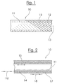
- FIG. 1 The illustration shows a simplified schematic view of a plastic tube, which is designated overall by the reference numeral 10.
- the plastic tube 10 is shown here in an intermediate phase of the production. It is a first of the first steps still two-layer plastic pipe, which is prepared starting from a prepared in a first process step tubular support 11, which is prepared for example by a conventional method by extrusion from a plastic such as a polyolefin ,
- the tubular support 11 may consist of a plastic without orientation.
- bands 12 are wound from a oriented in one direction plastic, in particular at a relatively shallow angle to the tube axis 13 as in FIG. 1 shown.
- the bands 12 are spirally wound around the tubular support 11, such that respective adjacent bands 12 abut one another, that is, are arranged in abutment.
- These bands 12 may consist of a chemically similar plastic as the carrier 11, for example also of a polyolefin, in particular of the same polyolefin as the carrier.
- the tapes are orientated in at least one direction by being previously drawn, for which they are heated to a temperature which is a little below the melting temperature of the particular plastic and then pulled so that they expand. This is done for example by means of an arrangement of rollers comprising pairs of rollers which run at different speeds and transport the belt so that it is stretched in the longitudinal direction.
- the thus obtained oriented strips 12 are wound from plastic onto the tubular support and then welded to it firmly, which can be done for example by means of laser radiation.
- a solid composite is created with a then two-layer tube from the carrier and the second outer layer formed from the bands. Due to the stretching, the bands have a different thermal expansion than the support tube. When heated, they have a tendency to pull together.
- the support tube (pipe core) 11 consists of a non-oriented ordinary plastic, which expands comparatively strong when heated.
- the effect is that the increase in length of the tubular support 11 (the core tube) is compensated by the decrease in length of the outer layer formed from the bands 12, so that the total tube has a lower thermal expansion than a plastic tube, which consists solely of a plastic of the type used in the support tube 11, or no thermal expansion in the axial direction (in the length direction) at all.
- FIG. 1 tube shown coated in a further operation with a third outer layer of plastic, which is for example extruded onto the formed from the bands 12 middle layer.
- This third layer serves primarily to create a pipe with a uniform smooth surface, which is needed, for example, to interconnect such pipes by means of sleeves or other connecting elements.
- the surface of the two-layer pipe after winding and welding the bands 12, however, is not sufficiently flat.
- the third layer then forms a final covering layer of the tube.
- This third layer may for example consist of a non-oriented plastic, which then again has a length extension when heated as a conventional plastic.
- FIG. 2 shows the longitudinal section through such a three-layer tube 10 according to the present invention after the winding and welding of the bands 12 and after the application of the third outer layer 17.
- This tube then consists of the inner layer 11, which is formed from the support tube 11, from a second middle layer 14, which has been formed from the previously applied bands, and from the third outer cover layer 17, which has subsequently been extruded, for example.
- the arrows 15 and 16 and 18 indicate that the inner layer 11 tries to expand in the longitudinal direction when heated, while the middle layer 14 has a tendency to shrink in length when heated, and the outer layer 17 in turn tends to elongate. As a result, corresponding voltage components are generated, which compensate each other.
- the particular advantage of the method according to the invention is that in this way material-homogeneous plastic pipes with reduced thermal expansion are obtainable, wherein the middle oriented layer 14 can compensate for the thermal expansion of the other two layers 11 and 17.
Claims (13)
- Procédé pour la fabrication d'un tube multicouches en matière plastique comprenant l'application d'au moins une bande en matière plastique sur un composant support en matière plastique, dans lequel, après l'application, cette au moins une bande en matière plastique est soudée avec le composant support, dans lequel un noyau de tube cylindrique (11) sert de composant support sur lequel on applique au moins une couche de renforcement comprenant cette au moins une bande en matière plastique (12), laquelle se compose d'une matière plastique qui présente un coefficient de dilatation thermique négatif, dans lequel cette au moins une bande en matière plastique (12) est enroulée selon un angle de 45° par rapport à l'axe de tube, ou de manière plus plate, sur le noyau de tube cylindrique (11) et cette au moins une bande en matière plastique (12) ayant obtenu une orientation dans au moins une direction grâce à un étirage, dans lequel le degré d'étirage de cette au moins une bande en matière plastique (12) orientée et appliquée et l'angle selon lequel cette au moins une bande en matière plastique est enroulée sur le noyau de tube cylindrique (11) sont choisis d'une manière telle, que la composante de contrainte axiale de la couche de renforcement ou la somme des composantes de contraintes axiales des couches de renforcement compense en cas d'échauffement la composante de contrainte axiale de la couche de noyau de tube ou la somme des composantes de contrainte axiales de la couche de noyau de tube et le cas échéant d'autres couches de tube de façon au moins partielle,
dans lequel cette au moins une bande en matière plastique (12) comprend au moins une couche d'une matière plastique à haut degré d'orientation dans au moins une direction, et cette au moins une bande en matière plastique (12) et le noyau de tube cylindrique (11) se composant d'une matière plastique chimiquement similaire. - Procédé selon la revendication 1, caractérisé en ce que le rapport des épaisseurs entre les couches de tube individuelles est choisi d'une manière telle, que la composante de contrainte axiale de la couche de renforcement ou la somme des composantes de contrainte axiales des couches de renforcement compense, en cas d'échauffement, la composante de contrainte axiale de la couche de noyau de tube ou la somme des composantes de contrainte axiales de la couche de noyau de tube et le cas échéant d'autres couches de tube de façon au moins partielle.
- Procédé selon la revendication 1 ou 2, caractérisé en ce que la dilatation thermique négative de la matière plastique de cette au moins une bande en matière plastique (12) est réversible, à savoir que la matière plastique se dilate de nouveau en cas de refroidissement.
- Procédé selon l'une des revendications 1 à 3, caractérisé en ce que cette au moins une bande en matière plastique (12) a obtenu une orientation dans au moins une direction grâce à un étirage à froid après l'extrusion de la bande de matière plastique, lequel s'effectue de préférence dans une plage de températures comprise entre près de 10° et près de 50°, également de préférence comprise entre près de 10° et près de 20° en-deçà de la température de fusion de la matière plastique.
- Procédé selon l'une des revendications 1 à 4, caractérisé en ce qu'au moins une bande de matière plastique (12) est enroulée sur le composant support en forme de tube (11) et est ensuite soudée de manière fixe avec le composant support en forme de tube sans ce faisant annuler l'orientation de la bande en matière plastique (12) concernant sa direction en longueur.
- Procédé selon l'une des revendications 1 à 5, caractérisé en ce qu'au moins deux couches de bandes en matière plastique (12) étirées, orientées dans au moins une direction sont appliquées successivement en se recouvrant les unes les autres sur le composant support (11) et sont soudées de manière fixe avec le composant support.
- Procédé selon la revendication 6, caractérisé en ce qu'au moins deux couches de bandes en matière plastique (12) étirées, orientées dans au moins une direction sont enroulées successivement en se recouvrant les unes les autres sur le composant support en forme de tube (11) et sont ensuite respectivement soudées de manière fixe avec le composant support en forme de tube ou la couche de renforcement située en-dessous.
- Procédé selon la revendication 7, caractérisé en ce qu'au moins deux couches de bandes en matière plastique (12) étirées, orientées dans au moins une direction sont enroulées successivement respectivement selon un angle par rapport à l'axe de tube (13) dans le sens de rotation contraire en se recouvrant les unes les autres sur le support en forme de tube (11).
- Procédé selon l'une des revendications 1 à 4, caractérisé en ce qu'au moins une bande en matière plastique (12) est apposée sensiblement en direction en longueur sur la surface du composant support (11) en forme de tube et est soudée avec le composant support.
- Procédé selon l'une des revendications 1 à 9, caractérisé en ce que cette au moins une bande en matière plastique (12) et le noyau de tube cylindrique (11) servant de composant support se composent de la même matière plastique.
- Tube multicouches en matière plastique, caractérisé en ce que celui-ci a été fabriqué selon un procédé avec les caractéristiques de l'une des revendications 1 à 10.
- Tube selon la revendication 11, caractérisé en ce que celui-ci est configuré, avec une homogénéité des matériaux ou de manière essentiellement à homogénéité des matériaux, à base de matières plastiques chimiquement identiques ou similaires.
- Tube selon l'une des revendications 11 ou 12, caractérisé en ce que celui-ci est un tube en matière plastique à au moins trois couches dont la couche du milieu (14) compense au moins partiellement la composante de contrainte axiale de la couche intérieure (11) et/ou de la couche extérieure en cas d'échauffement (17).
Applications Claiming Priority (2)
| Application Number | Priority Date | Filing Date | Title |
|---|---|---|---|
| DE102008012924A DE102008012924A1 (de) | 2008-03-06 | 2008-03-06 | Verfahren zur Herstellung eines Bauteils aus Kunststoff sowie nach diesem Verfahren hergestelltes Kunststoffbauteil |
| PCT/EP2009/052569 WO2009109609A1 (fr) | 2008-03-06 | 2009-03-05 | Procédé de production d'un tube multicouche en matière plastique, et tube en matière plastique fabriqué suivant ce procédé |
Publications (2)
| Publication Number | Publication Date |
|---|---|
| EP2254745A1 EP2254745A1 (fr) | 2010-12-01 |
| EP2254745B1 true EP2254745B1 (fr) | 2016-09-14 |
Family
ID=40823271
Family Applications (1)
| Application Number | Title | Priority Date | Filing Date |
|---|---|---|---|
| EP09717650.7A Not-in-force EP2254745B1 (fr) | 2008-03-06 | 2009-03-05 | Procédé de production d'un tube multicouche en matière plastique, et tube en matière plastique fabriqué suivant ce procédé |
Country Status (4)
| Country | Link |
|---|---|
| EP (1) | EP2254745B1 (fr) |
| DE (1) | DE102008012924A1 (fr) |
| PL (1) | PL2254745T3 (fr) |
| WO (1) | WO2009109609A1 (fr) |
Families Citing this family (5)
| Publication number | Priority date | Publication date | Assignee | Title |
|---|---|---|---|---|
| DE102010018799B4 (de) * | 2010-04-29 | 2015-06-18 | Semperit Ag Holding | Rohrförmiger Körper zur Förderung von festen, flüssigen und/oder gasförmigen Stoffen |
| DE102011108603A1 (de) | 2011-07-27 | 2013-01-31 | Friatec Aktiengesellschaft | Verbundkomponenten-Koppelsystem und Verfahren zum Vorbereiten der Kopplung einer Verbundkomponente an eine weitere Komponente |
| DE102013113664A1 (de) | 2013-12-06 | 2015-06-11 | Andreas Bersch | Kunststoffrohr und Herstellverfahren hierfür |
| JP2017506723A (ja) | 2013-12-06 | 2017-03-09 | タッペ,ミカエル | 合成材料管およびその製造方法 |
| DE102014111458A1 (de) | 2014-08-12 | 2016-02-18 | Norma Germany Gmbh | Fluidleitung |
Family Cites Families (4)
| Publication number | Priority date | Publication date | Assignee | Title |
|---|---|---|---|---|
| GB882736A (en) * | 1958-07-28 | 1961-11-22 | Polyymer Corp | Nylon tubing with braided cover and method of making same |
| CA1311595C (fr) * | 1987-10-09 | 1992-12-22 | David R. Nelson | Procede de fabrication de tuyau de materiau composite et materiel connexe |
| EP1314923B1 (fr) * | 2000-08-29 | 2006-07-26 | Sekisui Chemical Co., Ltd. | Tube haute pression composite et son procede de fabrication |
| ITTO20011161A1 (it) * | 2001-12-12 | 2003-06-12 | Fiatavio Spa | Metodo per la realizzazione di un involucro coibentato per un propulsore a razzo, ed involucro coibentato per un propulsore a razzo realizza |
-
2008
- 2008-03-06 DE DE102008012924A patent/DE102008012924A1/de not_active Withdrawn
-
2009
- 2009-03-05 WO PCT/EP2009/052569 patent/WO2009109609A1/fr active Application Filing
- 2009-03-05 PL PL09717650T patent/PL2254745T3/pl unknown
- 2009-03-05 EP EP09717650.7A patent/EP2254745B1/fr not_active Not-in-force
Also Published As
| Publication number | Publication date |
|---|---|
| WO2009109609A1 (fr) | 2009-09-11 |
| PL2254745T3 (pl) | 2017-03-31 |
| DE102008012924A1 (de) | 2009-09-10 |
| EP2254745A1 (fr) | 2010-12-01 |
Similar Documents
| Publication | Publication Date | Title |
|---|---|---|
| DE3135966C2 (de) | Verfahren zur Herstellung mehrschichtiger Schraubennahtrohre | |
| EP2254745B1 (fr) | Procédé de production d'un tube multicouche en matière plastique, et tube en matière plastique fabriqué suivant ce procédé | |
| DE2733048A1 (de) | Rohrverbindung und verfahren zu ihrer herstellung | |
| WO2000073695A1 (fr) | Tube d'acier thermo-isole pour canalisations de grands fonds, et son procede de production | |
| DE10009305A1 (de) | Leitungsrohr mit Rissstopper und Verfahren zur Herstellung eines solchen Leitungsrohrs | |
| DE2923544C2 (de) | Verfahren zur Herstellung eines Verbundrohres | |
| EP0111169A2 (fr) | Tube multicouche | |
| DE4323838A1 (de) | Verfahren zur Herstellung eines mehrschichtigen Leitungsrohres | |
| DE3104161A1 (de) | Kunststoffschlauch oder kunststoffrohr fuer den transport korrosionsfoerdernder medien | |
| DE19953737C1 (de) | Mehrschichtverbundrohr | |
| DE3023214A1 (de) | Verfahren zur herstellung eines verbundrohres | |
| EP2925463B2 (fr) | Procédé de production d'une gaine multicouches, gaine et installation de climatisation équipée d'une telle gaine | |
| DE2166791A1 (de) | Verfahren zum herstellen von rohren aus kunststoff-metall-laminaten | |
| EP0691193B1 (fr) | Procédé pour la fabrication continue d'un tube composite constitué d'un tube métallique et d'une tube intérieur en matière plastique | |
| EP3067607B1 (fr) | Conduite en acier comprenant une enveloppe de ballast et procede de production d'une telle conduite | |
| DE102008038039A1 (de) | Mehrschicht-Verbundrohr mit einer Polyvinylidenfluorid-Innenschicht | |
| DE3225869A1 (de) | Vorrichtung zur herstellung eines leitungsrohres aus kunststoff | |
| WO2008028866A1 (fr) | Procédé de fabrication d'une pièce cylindrique en forme de boudin | |
| EP1361038B1 (fr) | Méthode et procédé pour produire un tube composite | |
| DE102018132949A1 (de) | Rohr aus Stahl mit einer Kunststoffummantelung als Schutzschicht gegen mechanische Beschädigungen, Herstellverfahren hierzu und Rohrleitung hieraus | |
| EP1039200A2 (fr) | Tuyau composite metallo-plastique | |
| DE2650508A1 (de) | Rohr zur herstellung von unter druck stehenden fluessigkeiten fuehrenden leitungen | |
| EP3530434B1 (fr) | Procédé d'enrobage ultérieur d'une pièce tubulaire | |
| DE202022102049U1 (de) | Fernwärmerohre für die grabenlose Verlegung | |
| DE10334865B4 (de) | Verfahren zum Herstellen eines Wärmedämmschlauches |
Legal Events
| Date | Code | Title | Description |
|---|---|---|---|
| PUAI | Public reference made under article 153(3) epc to a published international application that has entered the european phase |
Free format text: ORIGINAL CODE: 0009012 |
|
| 17P | Request for examination filed |
Effective date: 20100901 |
|
| AK | Designated contracting states |
Kind code of ref document: A1 Designated state(s): AT BE BG CH CY CZ DE DK EE ES FI FR GB GR HR HU IE IS IT LI LT LU LV MC MK MT NL NO PL PT RO SE SI SK TR |
|
| AX | Request for extension of the european patent |
Extension state: AL BA RS |
|
| DAX | Request for extension of the european patent (deleted) | ||
| 17Q | First examination report despatched |
Effective date: 20120920 |
|
| GRAP | Despatch of communication of intention to grant a patent |
Free format text: ORIGINAL CODE: EPIDOSNIGR1 |
|
| INTG | Intention to grant announced |
Effective date: 20160323 |
|
| GRAS | Grant fee paid |
Free format text: ORIGINAL CODE: EPIDOSNIGR3 |
|
| GRAA | (expected) grant |
Free format text: ORIGINAL CODE: 0009210 |
|
| RAP1 | Party data changed (applicant data changed or rights of an application transferred) |
Owner name: EGEPLAST INTERNATIONAL GMBH |
|
| AK | Designated contracting states |
Kind code of ref document: B1 Designated state(s): AT BE BG CH CY CZ DE DK EE ES FI FR GB GR HR HU IE IS IT LI LT LU LV MC MK MT NL NO PL PT RO SE SI SK TR |
|
| REG | Reference to a national code |
Ref country code: GB Ref legal event code: FG4D Free format text: NOT ENGLISH |
|
| REG | Reference to a national code |
Ref country code: CH Ref legal event code: EP |
|
| REG | Reference to a national code |
Ref country code: IE Ref legal event code: FG4D Free format text: LANGUAGE OF EP DOCUMENT: GERMAN |
|
| REG | Reference to a national code |
Ref country code: AT Ref legal event code: REF Ref document number: 828453 Country of ref document: AT Kind code of ref document: T Effective date: 20161015 |
|
| REG | Reference to a national code |
Ref country code: DE Ref legal event code: R096 Ref document number: 502009013090 Country of ref document: DE |
|
| REG | Reference to a national code |
Ref country code: NL Ref legal event code: FP |
|
| REG | Reference to a national code |
Ref country code: LT Ref legal event code: MG4D |
|
| REG | Reference to a national code |
Ref country code: NO Ref legal event code: T2 Effective date: 20160914 |
|
| PG25 | Lapsed in a contracting state [announced via postgrant information from national office to epo] |
Ref country code: LT Free format text: LAPSE BECAUSE OF FAILURE TO SUBMIT A TRANSLATION OF THE DESCRIPTION OR TO PAY THE FEE WITHIN THE PRESCRIBED TIME-LIMIT Effective date: 20160914 Ref country code: FI Free format text: LAPSE BECAUSE OF FAILURE TO SUBMIT A TRANSLATION OF THE DESCRIPTION OR TO PAY THE FEE WITHIN THE PRESCRIBED TIME-LIMIT Effective date: 20160914 Ref country code: HR Free format text: LAPSE BECAUSE OF FAILURE TO SUBMIT A TRANSLATION OF THE DESCRIPTION OR TO PAY THE FEE WITHIN THE PRESCRIBED TIME-LIMIT Effective date: 20160914 |
|
| PG25 | Lapsed in a contracting state [announced via postgrant information from national office to epo] |
Ref country code: ES Free format text: LAPSE BECAUSE OF FAILURE TO SUBMIT A TRANSLATION OF THE DESCRIPTION OR TO PAY THE FEE WITHIN THE PRESCRIBED TIME-LIMIT Effective date: 20160914 Ref country code: LV Free format text: LAPSE BECAUSE OF FAILURE TO SUBMIT A TRANSLATION OF THE DESCRIPTION OR TO PAY THE FEE WITHIN THE PRESCRIBED TIME-LIMIT Effective date: 20160914 Ref country code: GR Free format text: LAPSE BECAUSE OF FAILURE TO SUBMIT A TRANSLATION OF THE DESCRIPTION OR TO PAY THE FEE WITHIN THE PRESCRIBED TIME-LIMIT Effective date: 20161215 Ref country code: SE Free format text: LAPSE BECAUSE OF FAILURE TO SUBMIT A TRANSLATION OF THE DESCRIPTION OR TO PAY THE FEE WITHIN THE PRESCRIBED TIME-LIMIT Effective date: 20160914 |
|
| PG25 | Lapsed in a contracting state [announced via postgrant information from national office to epo] |
Ref country code: RO Free format text: LAPSE BECAUSE OF FAILURE TO SUBMIT A TRANSLATION OF THE DESCRIPTION OR TO PAY THE FEE WITHIN THE PRESCRIBED TIME-LIMIT Effective date: 20160914 Ref country code: EE Free format text: LAPSE BECAUSE OF FAILURE TO SUBMIT A TRANSLATION OF THE DESCRIPTION OR TO PAY THE FEE WITHIN THE PRESCRIBED TIME-LIMIT Effective date: 20160914 |
|
| PG25 | Lapsed in a contracting state [announced via postgrant information from national office to epo] |
Ref country code: BG Free format text: LAPSE BECAUSE OF FAILURE TO SUBMIT A TRANSLATION OF THE DESCRIPTION OR TO PAY THE FEE WITHIN THE PRESCRIBED TIME-LIMIT Effective date: 20161214 Ref country code: PT Free format text: LAPSE BECAUSE OF FAILURE TO SUBMIT A TRANSLATION OF THE DESCRIPTION OR TO PAY THE FEE WITHIN THE PRESCRIBED TIME-LIMIT Effective date: 20170116 Ref country code: CZ Free format text: LAPSE BECAUSE OF FAILURE TO SUBMIT A TRANSLATION OF THE DESCRIPTION OR TO PAY THE FEE WITHIN THE PRESCRIBED TIME-LIMIT Effective date: 20160914 Ref country code: IS Free format text: LAPSE BECAUSE OF FAILURE TO SUBMIT A TRANSLATION OF THE DESCRIPTION OR TO PAY THE FEE WITHIN THE PRESCRIBED TIME-LIMIT Effective date: 20170114 Ref country code: SK Free format text: LAPSE BECAUSE OF FAILURE TO SUBMIT A TRANSLATION OF THE DESCRIPTION OR TO PAY THE FEE WITHIN THE PRESCRIBED TIME-LIMIT Effective date: 20160914 |
|
| REG | Reference to a national code |
Ref country code: DE Ref legal event code: R097 Ref document number: 502009013090 Country of ref document: DE |
|
| PLBE | No opposition filed within time limit |
Free format text: ORIGINAL CODE: 0009261 |
|
| STAA | Information on the status of an ep patent application or granted ep patent |
Free format text: STATUS: NO OPPOSITION FILED WITHIN TIME LIMIT |
|
| PG25 | Lapsed in a contracting state [announced via postgrant information from national office to epo] |
Ref country code: DK Free format text: LAPSE BECAUSE OF FAILURE TO SUBMIT A TRANSLATION OF THE DESCRIPTION OR TO PAY THE FEE WITHIN THE PRESCRIBED TIME-LIMIT Effective date: 20160914 |
|
| 26N | No opposition filed |
Effective date: 20170615 |
|
| PG25 | Lapsed in a contracting state [announced via postgrant information from national office to epo] |
Ref country code: MC Free format text: LAPSE BECAUSE OF FAILURE TO SUBMIT A TRANSLATION OF THE DESCRIPTION OR TO PAY THE FEE WITHIN THE PRESCRIBED TIME-LIMIT Effective date: 20160914 Ref country code: SI Free format text: LAPSE BECAUSE OF FAILURE TO SUBMIT A TRANSLATION OF THE DESCRIPTION OR TO PAY THE FEE WITHIN THE PRESCRIBED TIME-LIMIT Effective date: 20160914 |
|
| REG | Reference to a national code |
Ref country code: IE Ref legal event code: MM4A |
|
| REG | Reference to a national code |
Ref country code: FR Ref legal event code: ST Effective date: 20171130 |
|
| PG25 | Lapsed in a contracting state [announced via postgrant information from national office to epo] |
Ref country code: LU Free format text: LAPSE BECAUSE OF NON-PAYMENT OF DUE FEES Effective date: 20170305 Ref country code: FR Free format text: LAPSE BECAUSE OF NON-PAYMENT OF DUE FEES Effective date: 20170331 |
|
| PG25 | Lapsed in a contracting state [announced via postgrant information from national office to epo] |
Ref country code: IE Free format text: LAPSE BECAUSE OF NON-PAYMENT OF DUE FEES Effective date: 20170305 |
|
| PG25 | Lapsed in a contracting state [announced via postgrant information from national office to epo] |
Ref country code: MT Free format text: LAPSE BECAUSE OF FAILURE TO SUBMIT A TRANSLATION OF THE DESCRIPTION OR TO PAY THE FEE WITHIN THE PRESCRIBED TIME-LIMIT Effective date: 20160914 |
|
| PGFP | Annual fee paid to national office [announced via postgrant information from national office to epo] |
Ref country code: CH Payment date: 20190320 Year of fee payment: 11 Ref country code: IT Payment date: 20190325 Year of fee payment: 11 Ref country code: GB Payment date: 20190320 Year of fee payment: 11 Ref country code: PL Payment date: 20190301 Year of fee payment: 11 Ref country code: NO Payment date: 20190325 Year of fee payment: 11 |
|
| PGFP | Annual fee paid to national office [announced via postgrant information from national office to epo] |
Ref country code: AT Payment date: 20190321 Year of fee payment: 11 Ref country code: NL Payment date: 20190320 Year of fee payment: 11 Ref country code: BE Payment date: 20190320 Year of fee payment: 11 |
|
| PG25 | Lapsed in a contracting state [announced via postgrant information from national office to epo] |
Ref country code: HU Free format text: LAPSE BECAUSE OF FAILURE TO SUBMIT A TRANSLATION OF THE DESCRIPTION OR TO PAY THE FEE WITHIN THE PRESCRIBED TIME-LIMIT; INVALID AB INITIO Effective date: 20090305 |
|
| PGFP | Annual fee paid to national office [announced via postgrant information from national office to epo] |
Ref country code: DE Payment date: 20190401 Year of fee payment: 11 |
|
| PG25 | Lapsed in a contracting state [announced via postgrant information from national office to epo] |
Ref country code: CY Free format text: LAPSE BECAUSE OF NON-PAYMENT OF DUE FEES Effective date: 20160914 |
|
| PG25 | Lapsed in a contracting state [announced via postgrant information from national office to epo] |
Ref country code: MK Free format text: LAPSE BECAUSE OF FAILURE TO SUBMIT A TRANSLATION OF THE DESCRIPTION OR TO PAY THE FEE WITHIN THE PRESCRIBED TIME-LIMIT Effective date: 20160914 |
|
| PG25 | Lapsed in a contracting state [announced via postgrant information from national office to epo] |
Ref country code: TR Free format text: LAPSE BECAUSE OF FAILURE TO SUBMIT A TRANSLATION OF THE DESCRIPTION OR TO PAY THE FEE WITHIN THE PRESCRIBED TIME-LIMIT Effective date: 20160914 |
|
| REG | Reference to a national code |
Ref country code: DE Ref legal event code: R119 Ref document number: 502009013090 Country of ref document: DE |
|
| REG | Reference to a national code |
Ref country code: NO Ref legal event code: MMEP |
|
| REG | Reference to a national code |
Ref country code: CH Ref legal event code: PL |
|
| REG | Reference to a national code |
Ref country code: NL Ref legal event code: MM Effective date: 20200401 |
|
| REG | Reference to a national code |
Ref country code: AT Ref legal event code: MM01 Ref document number: 828453 Country of ref document: AT Kind code of ref document: T Effective date: 20200305 |
|
| REG | Reference to a national code |
Ref country code: BE Ref legal event code: MM Effective date: 20200331 |
|
| PG25 | Lapsed in a contracting state [announced via postgrant information from national office to epo] |
Ref country code: NL Free format text: LAPSE BECAUSE OF NON-PAYMENT OF DUE FEES Effective date: 20200401 |
|
| PG25 | Lapsed in a contracting state [announced via postgrant information from national office to epo] |
Ref country code: CH Free format text: LAPSE BECAUSE OF NON-PAYMENT OF DUE FEES Effective date: 20200331 Ref country code: NO Free format text: LAPSE BECAUSE OF NON-PAYMENT OF DUE FEES Effective date: 20200331 Ref country code: LI Free format text: LAPSE BECAUSE OF NON-PAYMENT OF DUE FEES Effective date: 20200331 Ref country code: AT Free format text: LAPSE BECAUSE OF NON-PAYMENT OF DUE FEES Effective date: 20200305 Ref country code: DE Free format text: LAPSE BECAUSE OF NON-PAYMENT OF DUE FEES Effective date: 20201001 |
|
| PG25 | Lapsed in a contracting state [announced via postgrant information from national office to epo] |
Ref country code: BE Free format text: LAPSE BECAUSE OF NON-PAYMENT OF DUE FEES Effective date: 20200331 |
|
| GBPC | Gb: european patent ceased through non-payment of renewal fee |
Effective date: 20200305 |
|
| PG25 | Lapsed in a contracting state [announced via postgrant information from national office to epo] |
Ref country code: GB Free format text: LAPSE BECAUSE OF NON-PAYMENT OF DUE FEES Effective date: 20200305 |
|
| PG25 | Lapsed in a contracting state [announced via postgrant information from national office to epo] |
Ref country code: IT Free format text: LAPSE BECAUSE OF NON-PAYMENT OF DUE FEES Effective date: 20200305 |
|
| PG25 | Lapsed in a contracting state [announced via postgrant information from national office to epo] |
Ref country code: PL Free format text: LAPSE BECAUSE OF NON-PAYMENT OF DUE FEES Effective date: 20200305 |