EP2254542B1 - Adaptateur de fiole - Google Patents
Adaptateur de fiole Download PDFInfo
- Publication number
- EP2254542B1 EP2254542B1 EP20090712800 EP09712800A EP2254542B1 EP 2254542 B1 EP2254542 B1 EP 2254542B1 EP 20090712800 EP20090712800 EP 20090712800 EP 09712800 A EP09712800 A EP 09712800A EP 2254542 B1 EP2254542 B1 EP 2254542B1
- Authority
- EP
- European Patent Office
- Prior art keywords
- vial
- approximately
- vial adaptor
- adaptor
- opening
- Prior art date
- Legal status (The legal status is an assumption and is not a legal conclusion. Google has not performed a legal analysis and makes no representation as to the accuracy of the status listed.)
- Active
Links
- 230000000149 penetrating effect Effects 0.000 claims abstract description 226
- 239000012530 fluid Substances 0.000 claims description 46
- 230000004888 barrier function Effects 0.000 claims description 23
- 239000012528 membrane Substances 0.000 claims description 21
- 238000004891 communication Methods 0.000 claims description 16
- 239000000356 contaminant Substances 0.000 claims description 8
- 239000012080 ambient air Substances 0.000 claims 2
- 230000001419 dependent effect Effects 0.000 claims 1
- 239000000463 material Substances 0.000 description 55
- 239000003814 drug Substances 0.000 description 23
- 125000006850 spacer group Chemical group 0.000 description 23
- 239000000853 adhesive Substances 0.000 description 13
- 230000001070 adhesive effect Effects 0.000 description 13
- 229940079593 drug Drugs 0.000 description 11
- 239000000126 substance Substances 0.000 description 10
- 230000035515 penetration Effects 0.000 description 8
- 239000004033 plastic Substances 0.000 description 8
- 229920003023 plastic Polymers 0.000 description 8
- 241000894006 Bacteria Species 0.000 description 7
- 238000011109 contamination Methods 0.000 description 7
- 229920001971 elastomer Polymers 0.000 description 7
- 244000052616 bacterial pathogen Species 0.000 description 6
- 239000011888 foil Substances 0.000 description 6
- 238000004519 manufacturing process Methods 0.000 description 6
- 241000700605 Viruses Species 0.000 description 5
- 230000001154 acute effect Effects 0.000 description 5
- 238000000034 method Methods 0.000 description 5
- -1 polypropylene Polymers 0.000 description 5
- 238000007789 sealing Methods 0.000 description 5
- 239000008186 active pharmaceutical agent Substances 0.000 description 4
- 229910052751 metal Inorganic materials 0.000 description 4
- 239000002184 metal Substances 0.000 description 4
- 229920000515 polycarbonate Polymers 0.000 description 4
- 230000007480 spreading Effects 0.000 description 4
- 239000011521 glass Substances 0.000 description 3
- 230000002209 hydrophobic effect Effects 0.000 description 3
- 239000007788 liquid Substances 0.000 description 3
- 230000007246 mechanism Effects 0.000 description 3
- 241001631457 Cannula Species 0.000 description 2
- 239000004425 Makrolon Substances 0.000 description 2
- 229910052782 aluminium Inorganic materials 0.000 description 2
- XAGFODPZIPBFFR-UHFFFAOYSA-N aluminium Chemical compound [Al] XAGFODPZIPBFFR-UHFFFAOYSA-N 0.000 description 2
- 230000008901 benefit Effects 0.000 description 2
- 239000002131 composite material Substances 0.000 description 2
- 230000008878 coupling Effects 0.000 description 2
- 238000010168 coupling process Methods 0.000 description 2
- 238000005859 coupling reaction Methods 0.000 description 2
- 238000013461 design Methods 0.000 description 2
- 238000001746 injection moulding Methods 0.000 description 2
- 238000012986 modification Methods 0.000 description 2
- 230000004048 modification Effects 0.000 description 2
- 239000004417 polycarbonate Substances 0.000 description 2
- 229920001296 polysiloxane Polymers 0.000 description 2
- 229920001343 polytetrafluoroethylene Polymers 0.000 description 2
- 239000004810 polytetrafluoroethylene Substances 0.000 description 2
- 230000008569 process Effects 0.000 description 2
- 230000001105 regulatory effect Effects 0.000 description 2
- 239000007779 soft material Substances 0.000 description 2
- 239000004743 Polypropylene Substances 0.000 description 1
- 239000003708 ampul Substances 0.000 description 1
- 239000005388 borosilicate glass Substances 0.000 description 1
- 229920005549 butyl rubber Polymers 0.000 description 1
- 239000002775 capsule Substances 0.000 description 1
- 230000000994 depressogenic effect Effects 0.000 description 1
- 239000000428 dust Substances 0.000 description 1
- 238000000605 extraction Methods 0.000 description 1
- 238000003780 insertion Methods 0.000 description 1
- 230000037431 insertion Effects 0.000 description 1
- 238000002483 medication Methods 0.000 description 1
- 201000002266 mite infestation Diseases 0.000 description 1
- 239000013618 particulate matter Substances 0.000 description 1
- 229920001084 poly(chloroprene) Polymers 0.000 description 1
- 229920001155 polypropylene Polymers 0.000 description 1
- 239000011148 porous material Substances 0.000 description 1
- 239000000843 powder Substances 0.000 description 1
- 239000012858 resilient material Substances 0.000 description 1
- 230000000717 retained effect Effects 0.000 description 1
- 238000013519 translation Methods 0.000 description 1
Images


Classifications
-
- A—HUMAN NECESSITIES
- A61—MEDICAL OR VETERINARY SCIENCE; HYGIENE
- A61J—CONTAINERS SPECIALLY ADAPTED FOR MEDICAL OR PHARMACEUTICAL PURPOSES; DEVICES OR METHODS SPECIALLY ADAPTED FOR BRINGING PHARMACEUTICAL PRODUCTS INTO PARTICULAR PHYSICAL OR ADMINISTERING FORMS; DEVICES FOR ADMINISTERING FOOD OR MEDICINES ORALLY; BABY COMFORTERS; DEVICES FOR RECEIVING SPITTLE
- A61J1/00—Containers specially adapted for medical or pharmaceutical purposes
- A61J1/14—Details; Accessories therefor
- A61J1/20—Arrangements for transferring or mixing fluids, e.g. from vial to syringe
- A61J1/2096—Combination of a vial and a syringe for transferring or mixing their contents
-
- A—HUMAN NECESSITIES
- A61—MEDICAL OR VETERINARY SCIENCE; HYGIENE
- A61J—CONTAINERS SPECIALLY ADAPTED FOR MEDICAL OR PHARMACEUTICAL PURPOSES; DEVICES OR METHODS SPECIALLY ADAPTED FOR BRINGING PHARMACEUTICAL PRODUCTS INTO PARTICULAR PHYSICAL OR ADMINISTERING FORMS; DEVICES FOR ADMINISTERING FOOD OR MEDICINES ORALLY; BABY COMFORTERS; DEVICES FOR RECEIVING SPITTLE
- A61J1/00—Containers specially adapted for medical or pharmaceutical purposes
- A61J1/14—Details; Accessories therefor
- A61J1/20—Arrangements for transferring or mixing fluids, e.g. from vial to syringe
- A61J1/2003—Accessories used in combination with means for transfer or mixing of fluids, e.g. for activating fluid flow, separating fluids, filtering fluid or venting
- A61J1/2006—Piercing means
- A61J1/201—Piercing means having one piercing end
-
- A—HUMAN NECESSITIES
- A61—MEDICAL OR VETERINARY SCIENCE; HYGIENE
- A61J—CONTAINERS SPECIALLY ADAPTED FOR MEDICAL OR PHARMACEUTICAL PURPOSES; DEVICES OR METHODS SPECIALLY ADAPTED FOR BRINGING PHARMACEUTICAL PRODUCTS INTO PARTICULAR PHYSICAL OR ADMINISTERING FORMS; DEVICES FOR ADMINISTERING FOOD OR MEDICINES ORALLY; BABY COMFORTERS; DEVICES FOR RECEIVING SPITTLE
- A61J1/00—Containers specially adapted for medical or pharmaceutical purposes
- A61J1/14—Details; Accessories therefor
- A61J1/20—Arrangements for transferring or mixing fluids, e.g. from vial to syringe
- A61J1/2003—Accessories used in combination with means for transfer or mixing of fluids, e.g. for activating fluid flow, separating fluids, filtering fluid or venting
- A61J1/2048—Connecting means
- A61J1/2055—Connecting means having gripping means
-
- A—HUMAN NECESSITIES
- A61—MEDICAL OR VETERINARY SCIENCE; HYGIENE
- A61J—CONTAINERS SPECIALLY ADAPTED FOR MEDICAL OR PHARMACEUTICAL PURPOSES; DEVICES OR METHODS SPECIALLY ADAPTED FOR BRINGING PHARMACEUTICAL PRODUCTS INTO PARTICULAR PHYSICAL OR ADMINISTERING FORMS; DEVICES FOR ADMINISTERING FOOD OR MEDICINES ORALLY; BABY COMFORTERS; DEVICES FOR RECEIVING SPITTLE
- A61J1/00—Containers specially adapted for medical or pharmaceutical purposes
- A61J1/14—Details; Accessories therefor
- A61J1/20—Arrangements for transferring or mixing fluids, e.g. from vial to syringe
- A61J1/2003—Accessories used in combination with means for transfer or mixing of fluids, e.g. for activating fluid flow, separating fluids, filtering fluid or venting
- A61J1/2068—Venting means
- A61J1/2075—Venting means for external venting
-
- A—HUMAN NECESSITIES
- A61—MEDICAL OR VETERINARY SCIENCE; HYGIENE
- A61J—CONTAINERS SPECIALLY ADAPTED FOR MEDICAL OR PHARMACEUTICAL PURPOSES; DEVICES OR METHODS SPECIALLY ADAPTED FOR BRINGING PHARMACEUTICAL PRODUCTS INTO PARTICULAR PHYSICAL OR ADMINISTERING FORMS; DEVICES FOR ADMINISTERING FOOD OR MEDICINES ORALLY; BABY COMFORTERS; DEVICES FOR RECEIVING SPITTLE
- A61J1/00—Containers specially adapted for medical or pharmaceutical purposes
- A61J1/14—Details; Accessories therefor
- A61J1/20—Arrangements for transferring or mixing fluids, e.g. from vial to syringe
- A61J1/2003—Accessories used in combination with means for transfer or mixing of fluids, e.g. for activating fluid flow, separating fluids, filtering fluid or venting
- A61J1/2079—Filtering means
- A61J1/2082—Filtering means for gas filtration
-
- A—HUMAN NECESSITIES
- A61—MEDICAL OR VETERINARY SCIENCE; HYGIENE
- A61M—DEVICES FOR INTRODUCING MEDIA INTO, OR ONTO, THE BODY; DEVICES FOR TRANSDUCING BODY MEDIA OR FOR TAKING MEDIA FROM THE BODY; DEVICES FOR PRODUCING OR ENDING SLEEP OR STUPOR
- A61M5/00—Devices for bringing media into the body in a subcutaneous, intra-vascular or intramuscular way; Accessories therefor, e.g. filling or cleaning devices, arm-rests
- A61M5/14—Infusion devices, e.g. infusing by gravity; Blood infusion; Accessories therefor
- A61M5/162—Needle sets, i.e. connections by puncture between reservoir and tube ; Connections between reservoir and tube
Definitions
- This invention relates generally to medical connectors through which fluids flow, and in particular, to medical connectors for use with medicament vials.
- Vials or ampules are routinely used in hospitals and other medical settings for storing medications in the form of liquids and powders, as well as in other forms such as capsules. Vials can have a tubular shape or a bottle-like shape with a neck, but are available in a variety of other shapes as well. Vials are typically made from glass, such as borosilicate glass, but can be made from any desired material such as polypropylene or any other suitable glass or plastic. The glass can be colorless or colored, typically amber, depending on the application and medication stored. Vials are available in a range of opening sizes. For example, vials are commercially available having 8 mm, 11 mm, 13 mm, 17 mm, 20 mm, and 28 mm opening sizes, among others.
- vials have a stopper (or sometimes referred to herein as septa or septum) to sealingly close the opening in the vial.
- a stopper or sometimes referred to herein as septa or septum
- Metal foil such as from aluminum, can be crimped or wrapped around the upper portion of the vial to secure the stopper to the vial in such a manner that an airtight seal can be created between the septum and the vial.
- the metal foil, or cap, as the term is used herein, can also prevent tampering and contamination of the vial.
- Some stoppers or septa permit easy access to the medication or other contents within the vial without requiring the user to remove the cap from the vial. Septa also provide the benefit of helping to protect the contents of the vial from contamination from bacteria, germs, viruses, or other contaminants.
- the soft material allows a medical syringe or spike to penetrate the septa and allows the septa to sealingly close around the cannula of the medical syringe or spike to prevent leakage or contamination.
- Septa can be partially or fully coated with a more durable material such as polytetrafluoroethylene (PTFE) for added durability.
- PTFE polytetrafluoroethylene
- the closure of the septum can be temporarily opened, pierced, or moved to allow fluid to flow from the vial through the cannula of the syringe or other connector.
- the cannula can be withdrawn from the septum and the soft material of the septum will typically reseal itself after the desired amount of medication is drawn through the cannula and the connector is removed.
- septa may vary from one vial to the next, due to the different sizes and configurations of the vials or septa, it may be difficult for a single vial adaptor to be optimally designed to work most effectively with a broad range of vial sizes and configurations. Thus, there is a need for a vial adaptor that is adaptable for a wide mange of vial sizes and configurations.
- vial adaptors and metal cannula syringes suffer from other drawbacks, including potentially exposing the syringe/vial adaptor user and recipient of the medicine to the harmful substances that are sometimes contained in the vials, either through inhalation or skin contact.
- US 2007/106244 , WO 2005/105014 & US 2003/153895 disclose vial adaptors.
- the adaptors are configured to attach to multiple types and/or sizes of vials. It is contemplated that the features of the various embodiments disclosed herein are combinable to form additional embodiments. Such combinations are within the scope of this disclosure.
- the present invention relates to a vial adaptor comprising a base comprising a first surface and a second surface an interface portion extending from said first surface , and a penetrating portion extending from said second surface, said base further comprising a shroud extending from said second surface and spaced apart from and surrounding at least a portion of said penetrating portion, said shroud comprising at least one deflectable tab wherein said at least one deflectable tab deflects about an axis of deflection extending generally parallel to a centerline axis through the penetrating portion .
- Some embodiments comprise a vial adaptor configured to be attachable to a vial so as to be in an operable position wherein contents of the vial can be removed through the vial adaptor, the vial having an opening and a seal wherein the seal defines a fluid barrier surface.
- the vial adaptor comprises a base comprising a first surface and a second surface a penetrating portion extending from said second surface.
- the penetrating portion may comprise an outer surface and a distal end portion, the penetrating portion being configured to be inserted through the seal in the vial past the fluid barrier surface so as to be positioned within an interior space of the vial.
- the vial adaptor also includes an interface portion extending from the first surface of the base and at least one deflectable tab, which may comprise a proximal end, a distal end, and a protruding portion, the proximal end being supported by the body portion and the distal end being unrestrained so as to allow at least the distal end of the tab to be deflectable away from the penetrating portion, the tab being bendable about an axis that is generally parallel with a centerline axis through the penetrating portion.
- the vial adaptor also comprises a first opening disposed axially through at least a portion of the interface portion and a second opening disposed axially through the penetrating portion, wherein the second opening comprises a first end portion and a second end portion and is configured such that the first end portion is in communication with the first opening and the second end portion passes through the outer surface of the penetrating portion.
- the operable position of the vial adaptor has a position of the vial adaptor relative to the vial where the second end portion of the second opening is positioned within the interior space of the vial.
- the operable position of the vial adaptor can be defined as the position of the vial adaptor relative to the vial when the second end portion of the second opening is positioned within the interior space of the vial.
- the vial adaptor can be configured to provide support to the vial in at least the axial direction so as to bias the vial adaptor at least a predetermined axial position relative to the vial such that the second end portion of the second opening is located within the interior space of the vial and at least one tab being configured to bias the vial adaptor to a predetermined axial position relative to the fluid barrier surface so as to minimize the distance between the second end portion of the second opening and the fluid barrier surface for a wide range of vial sizes.
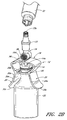
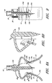
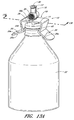
- Figure 1 is a perspective view of an arrangement of a vial adaptor.
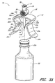
- Figure 2A is a perspective view of the arrangement of the vial adaptor of Figure 1 attached to a vial.
- Figure 2B is a perspective view of another arrangement of a vial adaptor attached to a vial.
- Figures 3A-3C are perspective views of the arrangement of the vial
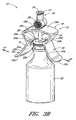
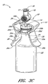
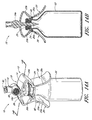
- Figures 3A-3C are perspective views of the arrangement of the vial adaptor of Figure 1 , depicting the vial adaptor being inserted into a vial.
- Figure 4 is a top view of the arrangement of the vial adaptor of Figure 1 .
- Figure 5 is a bottom view of the arrangement of the vial adaptor of Figure 1
- Figure 6 is a side view of the arrangement of the vial adaptor of Figure 1 from line 6-6 in Figure 4 .
- Figure 7 is a side view of the arrangement of the vial adaptor of Figure 1
- Figure 7 is a side view of the arrangement of the vial adaptor of Figure 1 from line 7-7 in Figure 4 .
- Figure 8A is section view of the arrangement of the vial adaptor of Figure 1 taken along the line 8A-8A in Figure 4 .
- Figure 8B is an enlarged section view of a portion of the arrangement of [0025]
- Figure 8B is an enlarged section view of a portion of the arrangement of the vial adaptor of Figure 1 generally defined by the curve 8B-8B in Figure 8A .
- Figure 9 is a section view of the arrangement of the vial adaptor of Figure 1 taken along the line 9-9 in Figure 4 .
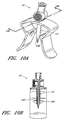
- Figure 10A is a perspective view of another arrangement of a vial adaptor.
- Figure 10B is section view of the arrangement of the vial adaptor of Figure 10A taken along the line 10B-10B in Figure 10A .
- Figure 11A is a perspective view of the arrangement of the vial adaptor of Figure 1 inserted into a 20 mm vial.
- Figure 11B is a section view of the arrangement of the vial adaptor of Figure 1 inserted into a 20 mm vial, taken along the line 11B-11B in Figure 11A .
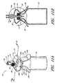
- Figure 11C is an enlarged section view of the arrangement of the vial adaptor of Figure 1 inserted into a 20 mm vial, taken along curve 11C-11C in Figure 11B .
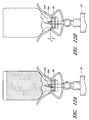
- Figure 12A is a side view of the arrangement of the vial adaptor of Figure 1 inserted into a 20 mm vial, with a portion of the 20 mm vial and a fluid occupying the majority of the volume within the vial shown in dashed lines for clarity.
- Figure 12B is a side view of the arrangement of the vial adaptor of Figure 1 inserted into a 20 mm vial, with a portion of the 20 mm vial and a fluid occupying the volume within the vial shown in dashed lines for clarity.
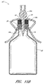
- Figure 13A is a perspective view of the arrangement of the vial adaptor of Figure 1 inserted into a 28 mm vial.
- Figure 13B is a section view of the arrangement of the vial adaptor of [0035]
- Figure 13B is a section view of the arrangement of the vial adaptor of Figure 1 inserted into a 28 mm vial, taken along the line 13B-13B in Figure 13A .
- Figure 13C is an enlarged section view of a portion of the arrangement of the vial adaptor of Figure 1 inserted into a 28 mm vial, taken along curve 13C-13C in Figure 13B .
- Figure 14A is a perspective view of the arrangement of the vial adaptor of
- Figure 14A is a perspective view of the arrangement of the vial adaptor of Figure 1 inserted into a 13 mm vial.
- Figure 14B is a section view of the arrangement of the vial adaptor of Figure 1 inserted into a 13 mm vial, taken along the line 14B-14B in Figure 14A .
- Figure 15A is a perspective view of another arrangement of a vial adaptor inserted into a 13 mm vial.
- Figure 15B is a section view of the arrangement the vial adaptor of Figure 15A inserted into a 13 mm vial, taken along the line 15B-15B in Figure 15A .
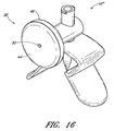
- Figure 16 is a perspective view of another arrangement of a vial adaptor.
- Figure 17 is an exploded perspective view of the arrangement of the vial adaptor shown in Figure 16 .
- Figure 18 is an exploded perspective view of some of the components of the arrangement of the filter member shown in Figure 16 .
- Figure 19 is a top view of the arrangement of the filter member shown in Figure 16 .
- Figure 20 is a section view of the arrangement of the filter member shown in Figure 16 , taken through line 20-20 in Figure 19 .
- Figure 21 is a perspective view of an embodiment of a vial adaptor.
- Figure 22 is another perspective view of the embodiment of the vial adaptor shown in Figure 21 .
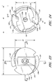
- Figure 23 is a top view of the embodiment of the vial adaptor shown in Figure 21 .
- Figure 24 is a bottom view of the embodiment of the vial adaptor shown in Figure 21 .
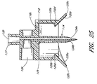
- Figure 25 is a section view of the embodiment of the vial adaptor shown in Figure 21 , taken through line 25-25 in Figure 23 .
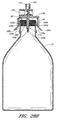
- Figure 26A is a perspective view of the embodiment of the vial adaptor of Figure 21 inserted into a 20 mm vial.
- Figure 26B is a section view of the embodiment of the vial adaptor of Figure 21 inserted into a 20 mm vial, taken through the axial centerline of the embodiment of the vial adaptor.
- Figure 27 is an exploded perspective view of the embodiment of the vial adaptor shown in Figure 21 having an embodiment of a filter member.
- Figure 28A is a perspective view of the embodiment of the vial adaptor of Figure 21 inserted into a 28 mm vial.
- Figure 28B is a section view of the embodiment of the vial adaptor of Figure 21 inserted into a 28 mm vial, taken along the line 28B-28B in Figure 28A .
- vial adaptors can have thicker cannulas and some degree of shielding of the cannulas to reduce the risk of the user inadvertently puncturing his or her skin.
- some vial adaptors can be designed to be removably supported by the lip or end portion of the vial so that the vial adaptor can be axially as well as radially secured by the vial.
- the medication can be withdrawn through an open end of the cannula.
- the vial is turned upside down so that the stopper end is oriented downward, allowing the medication to be withdrawn from the vial with only minimal penetration of the cannula through the septum.
- the depth of the cannula into the vial i.e., the length of the cannula that has penetrated past the inside, planar surface of the septum or stopper
- the medication With the vial in the upside down orientation, i.e., such that the stopper or septum side is facing downward, the medication will accumulate above the inside surface of the septum such that the end of the cannula can be positioned very close to the inside surface of the septum to extract as much medication as possible from the vial.
- some arrangements of the vial adaptor described herein achieve this for a wide range of vial sizes.
- Figure 1 is a perspective view of an arrangement of a vial adaptor 10 comprising a body portion 12, a penetrating portion 14, and an interface portion 16.
- the vial adaptor 10 can be formed without a penetrating portion 14, and can be used to seal an open vial that has already been opened or for which the septum or seal has been damaged or removed.
- the body portion 12 can comprise a central portion 18 (that can be curved) and one or more tabs 20 (which can be opposing) attached to the central portion 18.
- Each of the tabs 20 can be supported at a proximal end of the tab 20 by the central portion 18 of the body portion 12.
- the distal end of the tabs 20 can each be unrestrained so as to allow the tab to deflect outward.
- Figure 2A is a perspective view of the vial adaptor 10 of Figure 1 attached to a vial 22.
- the body portion 12, including the central portion 18 and tabs 20, can help removably secure the vial adaptor 10 to the outside surface of the vial 22 and can help facilitate the removal of the vial adaptor 10 from the vial 22, as will be discussed in greater detail below.
- the body portion 12 can define only one tab 20, as opposed to a pair of opposing tabs 20, the single tab being configured to removably secure the vial adaptor 10 to the outside surface of the vial 22 and to facilitate the removal of the vial adaptor 10 from the vial 22.
- the single tab 20 described above can be of any suitable configuration, including those set forth herein.
- the penetrating portion 14 can be supported by the body portion 12. As illustrated in Figure 1 , the penetrating portion 14 can project downward from the bottom or first surface 18a of the central portion 18 of the body portion 12.
- the penetrating portion 14 can comprise a cannula with a cylindrical outer surface 14a, an end portion 14b that can be configured to penetrate through a septum or stopper, and one or more axial openings 24 therethrough.
- the end portion 14b can be pointed (as illustrated), can be rounded or dulled, or can comprise any suitable shape.
- the penetrating portion 14 can have an opening 24a axially therethrough.
- the opening 24a can be configured to permit the contents of the vial 22 to be extracted therethrough.
- the vial adaptor 10 can have only one, or can have any number of openings 24 therethrough.
- the penetrating portion 14 can also have another opening 24b axially therethrough, for example as illustrated in Figures 5 , 6 , and 9 .
- the vial 22 can comprise a foil cap 26 that can be made from aluminum or any other suitable material.
- the term vial is meant to refer to the vial, the seal, the cap, and/or any other components or features associated with the vial. For convenience of illustration, the cap 26 has been omitted from some of the figures herein.
- the penetrating portion 14 can be inserted through a septum or stopper 28, or any other object that is typically used to seal the opening in the vial 22, by pushing the penetrating portion 14 of the vial adaptor 10 against the stopper 28 until the penetrating portion 14 protrudes through the stopper 28, as shown in Figure 2A .
- the term cap refers to the upper portion of the vial that secures a penetrable portion and can include the foil (metal or otherwise) that can be wrapped around the upper portion of the vial to secure the stopper to the vial and prevent tampering and contamination.
- the openings 24a, 24b can be positioned inside the vial 22 below the bottom surface of the stopper 28 so as to be in communication with the inside volume of the vial.
- the penetrating portion 14 can define a circular cross-section.
- the penetrating portion 14 can define an ovular, triangular, square, rectangular, or any other suitably shaped cross-section.
- a result of having a triangular, square, or other non-smoothly shaped cross-section can be that the penetrating portion can engage with the cap 26 or stopper 28 of the vial to inhibit the vial adaptor 10 from twisting or rotating relative to the vial.
- the cross-section of the penetrating portion 14 can be substantially smaller than its length.
- the cross-section of the penetrating portion 16 can be less than approximately 1/4th of its length.
- the cross-section of the penetrating portion 16 can be less than approximately 1/8th of its length, than approximately 1/10 th of its length.
- the cross-section of the penetrating portion 14 can define a diameter or size that can be approximately 5 mm.
- the penetrating portion 14 can define a cross-sectional diameter or size that can range from approximately 1 mm to approximately 4 mm, or from approximately 4 mm to approximately 7 mm, or from approximately 7 mm to approximately 10 mm.
- the penetrating portion 14 can define a relatively large cross-sectional diameter or size, the frictional force of the seal from the stopper 28 around the outer surface 14a of the penetrating portion 14 can provide some axial support to the vial adaptor 10 so as to inhibit the axial movement of the vial adaptor 10 relative to the vial 22.
- the outer surface 14a of the penetrating portion 14 can comprise features such as, but not limited to, ribs or striations that can be oriented perpendicular to the longitudinal axis of the penetrating portion 14, to increase the axial support provided by the stopper 28 to the penetrating portion 14.
- the vial adaptor 10 can be configured so as to control the depth of the end portion 14b of the penetrating portion 14 relative to the bottom surface of the cap 26 so as to increase or maximize the amount of fluid that can be withdrawn from the vial 22 when the vial is in a cap down orientation, even when used with a range of different vial sizes.
- the penetrating portion 14 can define a length (i.e., the distance from the first surface 18a to the end portion 14b of the penetrating portion 14) that can be approximately 20 mm. In some arrangements, the length of the penetrating portion 14 can be from approximately 12 mm to approximately 17 mm, or from approximately 17 mm to approximately 22 mm, or from approximately 22 mm to approximately 27 mm or from or to any value in these ranges.
- the penetrating portion 14 can define a length that can be approximately 60% of the diameter of the largest sized vial that the vial adaptor 10 is intended to be inserted into. In some arrangements, the penetrating portion 14 can define a length that can be from approximately 40% to approximately 65%, or from approximately 65% to approximately 90%, or from approximately 90% to approximately 125% of the approximate diameter of the largest sized vial that the vial adaptor 10 is intended to be inserted into.
- the penetrating portion 14 is not limited to the specific ranges of lengths, diameters, or other configurations described above.
- the penetrating portion 14 can be of any size or configuration that is suitable for the vial or vials for which the vial adaptor 10 is intended to be used.
- the interface portion 16 can be supported by the body portion 12. As illustrated in Figure 1 , the interface portion 16 can project upward from the upper or second surface 18b of the central portion 18 of the body portion 12. In some arrangements, the interface portion 16 can comprise a cylindrical outer surface and a third opening 30 axially disposed through at least a portion of the interface portion 16. In the illustrated arrangement, as most clearly shown in Figures 4 and 9 , the opening 30 can be in fluid communication with the opening 24a such that the contents of the vial 22 can pass from the opening 24a through the third opening 30. In some arrangements, the opening 30 can be sealed or sealable.
- any of a variety of suitable means for sealably closing the interface portion 16 of the vial adaptor 10 can be used to prevent the contents of the vial 22 from flowing out of the vial 22 when the vial adaptor 10 is inserted therein, as well as to seal the vial adaptor 10 and vial 22 from contamination from bacteria, germs, or other contaminants.
- the closing means or mechanisms can function to prevent and/or impede the contents of the vial 22 from escaping from or entering into the vial, while allowing the contents of the vial 22 to flow through the vial adaptor 10 when the closing means is opened or engaged with a corresponding male tipped connector or syringe or otherwise.
- terms such as “closed” or “sealed” should be understood as obstructions or barriers to fluid flow. These terms should not be understood to require that a particular structure or configuration achieves a complete fluid closure in all circumstances.
- the interface portion 16 can be configured to be connectable with any suitable medical connector or fluid flow connector, such as, without limitation, a male Luer connector.
- the interface portion 16 can comprise a flange, protrusions (which can be opposing), or threads 17 to aid in coupling the vial adaptor 10 with the medical connector, a medical device, or other instrument.
- the interface portion 16 can define a generally smooth cylindrical surface without such flange, protrusions, or threads.
- the medical connector, a medical device, or other instrument can be secured to the interface portion 16 with adhesive or any other bonding or adhesive material.
- the interface portion 16 can be configured to accept any suitable medical connector, such as a syringe 32 or sealable medical connector 33, or other connectors capable of sealing upon removal of a medical device therefrom.
- a syringe 32 or sealable medical connector 33 or other connectors capable of sealing upon removal of a medical device therefrom.
- the flange 17 can be sized and configured to accept the Clave® connector, available from ICU Medical, Inc. of San Clemente, California. Certain features of the Clave® connector are disclosed in U.S. Pat. No. 5,685,866 . Connectors of many other varieties, including other needleless connectors, can also be used.
- the medical connector 33 can be any suitable device, currently available or later developed.
- the medical connector 33 can have a sealable end portion 33a.
- the connector 33 can be sealable so that a user or practitioner can clean or swab the surface thereof without contaminating the contents of the vial.
- a sealable female end can also prevent the contents of the vial from leaking when the vial adaptor 10 is attached thereto. This can be particularly important in the field of oncology, where many of the fluids that are contained in the vials can be very harmful if touched or inhaled. Further, the sealable female end can prevent foreign substances, various airborne viruses, bacteria, dust, spores, molds, and other unsanitary and harmful debris or contaminants from entering of the vial.
- the sealable end portion 33a can comprise a soft or rigid poppet that can be depressed by a syringe or other suitable male medical implement. In some arrangements, the sealable end portion 33a can comprise a deformable rubber barrier having a slit, or other self-sealing mechanism incorporated therein.
- the medical connector 33 or a portion of the medical connector 33 can be integrally formed with the vial adaptor 10. In some arrangements, the syringe 32 or a portion of the syringe 32 can be integrally formed with the vial adaptor 10. In some arrangements, the syringe 32 or female connector 33 can be separately formed and can be removably or fixedly attached to the vial adaptor 10.
- the vial adaptor 10 can be positioned above the top of the stopper 28 of the vial 22 so that the axial center of the penetrating portion 14 is approximately aligned with the axial center of the rubber septum or stopper 28 (as indicated by the centerline C).
- the penetrating portion 14 can be introduced into the stopper 28, as illustrated in Figure 3B .
- the stopper 28 of the vial 22 can eventually contact the inside surface 20a of the tabs 20. Further axial force can cause the deflectable tabs 20 to spread apart (e.g., in opposing directions as shown by arrows A1 and A2) so that the penetrating portion 14 of the vial adaptor 10 can be further inserted into the vial.
- the tabs 20 can be configured so that a user can easily spread the tabs 20 apart by grasping or otherwise exerting a force on the inside surface of the end portions 20c of the tabs 20 and deflecting the tabs 20 away from the vial.
- the vial adaptor 10 can be inserted into the vial such that the end portion 14b of the penetrating portion 14 protrudes through the stopper 28 to a sufficient distance so that the one opening 24 in the penetrating portion 14 can be in communication with the inside volume of the vial 22. In this configuration, the contents of the vial 22 can be extracted through the opening or openings 24.
- the vial adaptor 10 can be configured to control the depth of penetration of the penetrating portion 14 into the vial for a multitude of the vial sizes so as to increase or maximize the amount of medicament or other substance that can be extracted from the vial through the vial adaptor 10.
- Figures 4 and 5 depict top and bottom views of the vial adaptor 10, respectively, while Figures 6 and 7 depict side views of the vial adaptor 10, respectively, as defined in Figure 4 .
- Figures 8A and 9 depict section views of the vial adaptor 10 as defined in Figure 4 .
- the body portion 12 can comprise a pair of opposing tabs 20 attached to the central portion 18.
- the tabs 20 each can define an inside surface 20a, an abutment surface 20b, an end portion 20c, and a protruding portion 20d.
- the abutment surfaces 20b and protruding portions 20d can aid in removably securing the vial adaptor 10 to the vial 22.
- each tab 20 can be supported by and attached to the end portion 18c of the central portion 18.
- the end portion 18c can be curved, as illustrated most clearly in Figure 6 .
- the first portion of each tab 20 (i.e., the portion of each tab 20 approximately above the abutment surfaces 20b and below the end portion 18c of the central portion 18) can angle inwardly toward the penetrating portion 14.
- the first portion of each tab 20 can taper inwardly at an angle ⁇ 1 (defined in Figure 6 ) that can be approximately 45° relative to a vertical plane, or from approximately 25° to approximately 40°, or from approximately 40° to approximately 55° relative to a vertical plane.
- the length of the first portion of each tab 20 can be less than the length of the penetrating portion 14.
- the length of the first portion of each tab 20 can be less than 3/4 of the length of the penetrating portion 14, than 1/2 the length of the penetrating portion 14.
- the length of the first portion of each tab 20 can be from approximately 50% to approximately 60%, or from approximately 60% to approximately 70%, or from approximately 70% to approximately 80% of the length of the penetrating portion 14, or from or to any value within these ranges. In some embodiments, the length of the first portion of each tab 20 can be approximately 13 mm.
- the length of the first portion of each tab 20 can be from approximately 10 mm to approximately 12.5 mm, or from approximately 12.5 mm to approximately 15 mm, or from approximately 15 mm to approximately 17.5 mm or from or to any value in these ranges.
- the end portion 20c can be approximately defined as the portion of the tabs 20 below the abutment surfaces 20b.
- the length of the end portion 20c of each tab 20 can be greater than the length of the penetrating portion 14.
- the length of the end portion 20c of each tab 20 can be at least approximately 1/4 larger or at least approximately 1/2 larger than the penetrating portion.
- the length of the end portion 20c of each tab 20 can be from approximately 110% to approximately 120%, or from approximately 120% to approximately 140%, or from approximately 140% to approximately 160% of the length of the penetrating portion 14.
- the length of the end portion 20c of each tab 20 can be approximately 23 mm.
- the length of the end portion 20c can be from approximately 18 mm to approximately 22 mm, or from approximately 22 mm to approximately 26 mm, or from approximately 26 mm to approximately 30 mm or from or to any value in these ranges.
- the end portion 20c of each tab 20 can taper outwardly away from the penetrating portion 14. In some embodiments, the end portion 20c of each tab 20 can taper outwardly at an angle ⁇ 2 (defined in Figure 6 ) that can be approximately 25° relative to a vertical plane, or from approximately 15° to approximately 30°, or from approximately 30° to approximately 45° relative to a vertical plane.
- ⁇ 2 defined in Figure 6
- the tabs 20 can define generally planar side surfaces 20e that, for each tab 20, can be opposing and generally parallel to one another.
- the width of each tab 20 (represented by "W" in Figure 4 , which can be the distance between the opposing side surfaces 20e for each tab 20) can be substantially greater than the diameter or size of the cross-section of the penetrating portion 14.
- the width of each tab 20 can be at least approximately twice as large or at least approximately three times as large as the diameter or size of the cross-section of the penetrating portion.
- the width of each tab 20 can be from approximately 200% to approximately 325%, or from approximately 325% to approximately 450%, or from approximately 450% to approximately 600% of the diameter or size of the cross-section of the penetrating portion 14. In some arrangements, the width of each tab 20 can be approximately 19 mm. In some arrangements, the width of each tab 20 can be from approximately 10 mm to approximately 15 mm, or from approximately 15 mm to approximately 20 mm, or from approximately 20 mm to approximately 25 mm or from or to any value in these ranges.
- the width of each tab 20 can be based on the diameter of the largest sized vial of the vial adaptor 10 is intended to be inserted into.
- the width W of each tab 20 can be from approximately 50% to approximately 75%, or from approximately 75% to approximately 100%, or from approximately 100% to approximately 125% of the diameter of the opening of the largest sized vial that the vial adaptor 10 is intended to be inserted into.
- the thickness of the material forming each tab 20 can be significantly less than the diameter or size of the cross-section of the penetrating portion 14.
- the thickness "t" of the material forming each tab 20 can be less than approximately half than approximately one-quarter of the diameter or size of the cross-section of the penetrating portion 14.
- the thickness "t" of the material forming each tab 20 can be approximately 40% of the diameter or size of the cross-section of the penetrating portion 14, or from approximately 25% to approximately 40%, or from approximately 40% to approximately 55%, or from approximately 55% to approximately 70% of the diameter or size of the cross-section of the penetrating portion 14, or from or to any value in these ranges.
- the thickness of the material forming each tab 20 can be approximately 1.5 mm. In some embodiments, the thickness "t" of the material forming each tab 20 can be from approximately 1 mm to approximately 1.5 mm, or from approximately 1.5 mm to approximately 2 mm, or from approximately 2 mm to approximately 2.5 mm or from or to any value in these ranges.
- each tab 20 is not limited to any of the specific sizes, ranges, or configurations described above.
- Each tab 20 can have any length, taper angle, thickness, width, size or configuration that is suitable for the vial or vials for which the vial adaptor 10 is intended to be used, or for the material that is chosen for each tab 20 or for any other components or features of the vial adaptor 10.
- each tab 20 can define a different size, shape, or other configuration as compared to any other tab 20 formed on the vial adaptor.
- the central portion 18 can define two generally planar side surfaces 18d that can be opposing and generally parallel to one another.
- the width of the central portion 18 (represented by "W" in Figure 4 , which can be the distance between the opposing side surfaces 18d of the central portion 18) can be approximately 19 mm.
- the width the central portion 18 can be significantly greater than the diameter or size of the cross-section of the penetrating portion 14.
- the width of the central portion 18 can be at least approximately twice or three times as large as the diameter or size of the cross-section of the penetrating portion.
- the width of the central portion 18 can be approximately at least approximately 400% of the diameter or size of the cross-section of the penetrating portion 14. In some arrangements, the width of the central portion 18 can be from approximately 200% to approximately 325%, or from approximately 325% to approximately 450%, or from approximately 450% to approximately 600% of the diameter or size of the cross-section of the penetrating portion 14. In some arrangements, the width of the central portion 18 can be approximately 19 mm. In some arrangements, the width of the central portion 18 can be from approximately 10 mm to approximately 15 mm, or from approximately 15 mm to approximately 20 mm, or from approximately 20 mm to approximately 25 mm or from or to any value in these ranges.
- the thickness of the material forming the central portion 18 (represented by "t" in Figure 6 ) can be significantly less than the diameter or size of the cross-section of the penetrating portion 14.
- the thickness "t" of the material forming the central portion 18 can be less than approximately half than approximately three-quarters of the diameter or size of the cross-section of the penetrating portion 14.
- the thickness "t" of the material forming the central portion 18 can be approximately 40% of the diameter or size of the cross-section of the penetrating portion 14, or from approximately 25% to approximately 40%, or from approximately 40% to approximately 55%, or from approximately 55% to approximately 70% of the diameter or size of the cross-section of the penetrating portion 14, or from or to any value in these ranges.
- the thickness of the material forming the central portion 18 can be approximately 1.5 mm. In some arrangements, the thickness "t" of the material forming the central portion 18 can be from approximately 1 mm to approximately 1.5 mm, or from approximately 1.5 mm to approximately 2 mm, or from approximately 2 mm to approximately 2.5 mm or from or to any value in these ranges.
- the central portion 18 can define a curved surface (as most clearly seen in Figures 6 and 7 ).
- the radius of curvature of the central portion 18 (that can be, but is not required to be, curved) can be significantly greater than the radius of the cross-section of the penetrating portion 14.
- the radius of curvature of the central portion 18 can be approximately 3 cm.
- the radius of curvature of the central portion 18 can be from approximately 2 cm to approximately 4 cm, or from approximately 4 cm to approximately 6 cm, or from approximately 6 cm to approximately 8 cm or to or from any value within these ranges.
- the size and configuration of the central portion 18 is not limited to the specific ranges or configurations described above.
- the central portion 18 can be of any size or configuration that is suitable for the vial or vials for which the vial adaptor 10 is intended to be used, or for the material that is chosen for the central portion 18 or for any other components or features of the vial adaptor 10.
- the width and thickness, or other aspects of the size and configuration of the central portion 18, can be the same as, or different than, that of the tabs 20 formed on the vial adaptor.
- the tabs 20 can each be sized and configured such that a portion of the inside surface 20a can slidingly receive the outer, generally cylindrical surface of the stopper 28 when the vial adaptor 10 is inserted into a vial.
- the abutment surfaces 20b can each be configured to inhibit the vial adaptor 10 from moving axially away from the vial 22 when the vial adaptor 10 is inserted into the vial 22 to a sufficient distance such that the abutment surfaces 20b overlap an adjacent protruding surface or surfaces on the vial 22 or stopper 28.
- the distance D1 represents the distance between the upper inside surface 18a of the body portion 18 and the abutment surfaces 20b.
- the vial adaptor 10 in the pre-stressed state, can be sized and configured such that the distance D1 can be significantly less than the length of the penetrating portion 14.
- the distance D1 in the pre-stressed state, can be less than approximately three-quarters, than approximately half of the length of the penetrating portion 14.
- the distance D1 can be from approximately 40% to approximately 50%, or from approximately 50% to approximately 60%, or from approximately 60% to approximately 70% of the length of the penetrating portion 14.
- the vial adaptor 10 in the pre-stressed state, can be sized and configured such that the distance D1 is from approximately 7 mm to approximately 10 mm, or from approximately 10 mm to approximately 13 mm, or from approximately 13 mm to approximately 16 mm or to or from any value in these ranges.
- the vial adaptor 10 and any components or features thereof is not limited to the specific ranges or configurations described above.
- the vial adaptor 10 can be of any size or configuration that is suitable for the vial or vials for which the vial or vial adaptor 10 is intended to be used.
- the vial adaptor 10 can be configured such that the vial adaptor 10 can be attached to a wide range of vials having a wide range of cap or stopper diameters.
- the central portion 18 and tabs 20 can be configured so as to be elastically bendable or deformable by a user to attach to or fit around a wide range of vial cap diameters.
- Figure 6 which is a side view of the vial adaptor 10 in a pre-installed state (i.e., before the vial adaptor 10 is inserted into the vial 22), the protruding portions 20d on the tabs 20 of the vial adaptor 10 can define a distance therebetween (represented by distance D2).
- the distance D2 represents the length across the constricted portion of the vial adaptor 10 in the relaxed or pre-stressed state.
- the vial adaptor 10 in the pre-stressed state, can be sized and configured such that the distance D2 can be significantly less than the length of the penetrating portion 14.
- the vial adaptor 10 in the pre-installed state, can be sized and configured such that the distance D2 is less than approximately three-quarters than approximately half as large as the length of the penetrating portion 14.
- the vial adaptor 10 in the pre-stressed state, can be sized and configured such that the distance D2 is approximately 14 mm. In some arrangements, in the pre-installed state, the vial adaptor 10 can be sized and configured such that the distance D2 is from approximately 10 mm to approximately 13 mm, or from approximately 13 mm to approximately 16 mm, or from approximately 16 mm to approximately 19 mm or from or to any value in these ranges. However, the vial adaptor 10 and any components or features thereof is not limited to the specific ranges or configurations described above. The vial adaptor 10 can be of any size or configuration that is suitable for the vial or vials for which the vial adaptor 10 is intended to be attached.
- the vial adaptor 10 can be configured such that, when the vial adaptor 10 is attached to a vial, the tabs can be deflected and spread apart (either by the user grasping and deflecting the end portions 20c of the tabs 20 or from the contact between the vial and the inside surface 20a of the tabs 20) so as to accommodate a vial having a cap or stopper diameter that is larger than the distance D2 between the opposing protruding portions 20d in the relaxed state.
- the vial adaptor 10 can be sized and configured such that, when the tabs 20 are spread apart, the distance D2 between the protruding portions 20d is significantly greater than the distance D2 between the protruding portions 20d when the vial adaptor 10 is in the relaxed state.
- the vial adaptor 10 can be sized and configured such that the distance between the protruding portions 20d when the tabs 20 are fully spread apart (i.e., when the vial adaptor 10 is mounted to a vial) can be at least approximately 50% larger than the distance between the protruding portions 20d when the tabs 20 are in the relaxed state.
- the vial adaptor 10 can be sized and configured such that the distance between the protruding portions 20d when the tabs 20 are spread apart or when the vial adaptor 110 is mounted to a vial is from approximately 120% to approximately 135%, or from approximately 135% to approximately 150%, or from approximately 150% to approximately 165% or to or from any value within these ranges, of the distance between the protruding portions 20d when the tabs 20 are in the relaxed state.
- the vial adaptor 10 can be sized and configured such that, when the tabs 20 are spread apart, the distance D2 between the protruding portions 20d can be from approximately 16 mm to approximately 20 mm, or from approximately 20 mm to approximately 24 mm, or from approximately 24 mm to approximately 28 mm, or from approximately 28 mm to approximately 32 mm or from or to any value in these ranges.
- the vial adaptor 10 and any components or features thereof is not limited to the specific ranges or configurations described above.
- the vial adaptor 10 can be of any size or configuration that is suitable for the vial or vials for which the vial adaptor 10 is intended to be attached.
- each tab 20 can be configured to have an outward flare or other structure to permit the user to easily grasp and deflect each of the tabs 20 radially outward so as to deflect away from the vial and, consequently, deflect each of the protruding portions 20d radially outward away from the vial so that the abutment surfaces 20b no longer overlap the protruding surface or surfaces on the vial 22, stopper 28, or cap.
- the end portions 20c can be configured so that a user gripping or contacting the end portions 20c of the tabs 20 with one hand and holding the vial 22 with the other can exert an axial, upward force on the vial adaptor 10 relative to the vial 22 so as to remove the vial adaptor 10 from the vial 22.
- the end portion 20c of each tab 20 can comprise channels, scores, protrusions, pits, a gnurled texture, soft rubber, or any other features, materials, or textures to prevent a user's fingers or hands from slipping relative to the surface of the end portion 20c of each tab 20.
- the distal end portions of the end portions 20c can be configured to define an outwardly curved or flared surface to better enable a user to access or grasp the inside surface 20a of the tabs 20.
- the curved or flared surface of the end portions 20c of the tabs 20 better enable the user to slide his or her finger or fingers underneath the tabs 20 so that the user can exert a radially outward pressure on the tabs 20 to spread the tabs radially outward.
- the end of each end portion 20c can be rounded or curved. This can be done to eliminate or soften otherwise sharp corners.
- the central portion 18 and tabs 20 can be configured so as to elastically deform or deflect so that the protruding portions 20d deflect outwardly over a wide range of distances to enable the vial adaptor 10 to accommodate a wide range of vial sizes.
- the central portion 18 and tabs 20 can be shaped and configured and made from a material that permits a significant amount of the elastic deflection while still allowing the tabs 20 and protruding portions 20d to exert a radially inward force sufficient to adequately secure the vial adaptor 10 to the vial.
- the central portion 18 in a relaxed state (i.e. before the vial adaptor 10 is inserted into a vial), can define a curved profile, as shown most clearly in the side view of Figure 6 .
- the vial adaptor when the vial adaptor is inserted into a larger vial, such as but not limited to the 28 mm vial illustrated in Figure 13B , and the tabs 20 can be deflected radially outwardly away from the protruding portion 14, the central portion 18 can be elastically deformed so as to move toward an approximately flat profile.
- the relaxed state curvature of the central portion 18 described above can increase the flexibility of the central portion 18, can permit the protruding portions 20d to deflect or bend outwardly over a greater distance or range of distances, and also can increase the radial inward force that the tabs 20 exert on the vial when the tabs 20 are deflected outwardly so as to allow the vial adaptor 10 to be adequately secured to a vial, without increasing the thickness of the material used to form the central portion 18.
- the central portion 18 can be caused to bend so that the end portions 18c of the central portion 18 can rotate and deflect upwardly.
- the tabs 20 when the vial adaptor 10 has been inserted into a 28 mm vial, the tabs 20 are configured to deflect outwardly from the relaxed state, causing the central portion 18 to deflect to a more planar shape (i.e. such that the end portions 18c have been caused to deflect and rotate upwardly).
- the taper angle ⁇ 1 can be reduced relative to a vertical plane, which increases the distance between the opposing protruding portions 20d.
- the curvature of the central portion 18 can provide for a greater expansion of the protruding portions 20d of the tabs 20.
- the tabs 20 can be integrally formed with the central portion 18.
- the tabs 20 can be formed separately and fused, welded, or otherwise attached to the central portion 18 with adhesive or other suitable fastening substances or materials, such as, without limitation, screws, rivets, or pins.
- the central portion 18 and the tabs 20 can be configured to be bendable so as to deflect when the vial adaptor 10 is inserted over the cap portion of a vial.
- the body portion 12 can define a constricted portion such as, but not limited to, the distance between protruding portions 20d that is narrower than the diameter of the cap or neck on the vial into which the vial adaptor 10 is to be inserted, so that the tabs 20 deflect outward (as indicated by the arrows A1 and A2 in Figure 3B ) as the penetrating portion 14 is being inserted into and through the stopper 28.
- the deflected tabs 20 can each exert a radial force directed toward the axial center of the vial adaptor 10 that is commensurate with the magnitude of their deflection so that the tabs 20 exert a reactive force on the vial and/or vial cap when the vial adaptor 10 is attached to the vial.
- each of the tabs 20 can also be configured so as to align the axial centerline of the vial adaptor 10 with the axial centerline of the vial to which the vial adaptor 10 is attached.
- the tabs 20 can each have an inside surface 26a and/or a depression 34 that are configured to contact a portion of the typically cylindrical outside surface 22a of the vial 22 (shown in Figure 3A ) or the typically cylindrical outside surface of the stopper 28 (shown in Figure 3A ) or cap 26.
- the inside surface 20a and/or depressions 34 can each bias the vial 22 to remain aligned with the axial centerline of the vial adaptor 10 and can prevent the tabs 20 from sliding laterally relative to the vial 22.
- the depressions 34 can each define a first surface portion 34a that can be configured to contact a portion of the generally cylindrical outside surface 22a of the vial 22 (shown in Figure 3A ) or the cylindrical outside surface of the stopper 28 or other surface of the vial 22.
- the first surface portion 34a can define a curved surface.
- the first surface portion 34a can define two generally planar surfaces defining a "V" shaped groove, which can be configured to contact a portion of the cylindrical outside surface 22a of the vial 22 or the generally cylindrical outside surface of the stopper 28 or cap 26 (see Figure 2A ) so as to bias the tabs 20 to remain aligned with the axial centerline of the vial 22 and to inhibit the tabs 20 from sliding laterally relative to the vial 22.
- the tabs 20 can each define a pair of protrusions or bumps that can be spaced apart from one another instead of the depression 34.
- the protrusions or bumps can be configured to contact a portion of the typically cylindrical outside surface 22a of the vial 22 (shown in Figure 3A ) or the typically cylindrical outside surface of the stopper 28 (shown in Figure 3A ) or cap 26. Similar to the depressions 34 described above, among other things, the protrusions can bias the vial 22 to remain aligned with the axial centerline of the vial adaptor 10 and can prevent the tabs 20 from sliding laterally relative to the vial 22.
- the protrusions can be configured to contact a portion of the cylindrical outside surface 22a of the vial 22 or the generally cylindrical outside surface of the stopper 28 or cap 26 so as to bias the tabs 20 to remain aligned with the axial centerline of the vial 22 and to inhibit the tabs 20 from sliding laterally relative to the vial 22.
- the depressions 34 can each comprise a second surface portion 34b.
- the second surface portion 34b can be configured to interact with the planar surface or edge portion of a protruding lip portion 40 of a vial so as to bias the cap, stopper, or other protruding portion of a vial to remain positioned within the depression 34 of each tab 20 and to inhibit (but not necessarily prevent) further axial movement of the vial adaptor 10 into the vial 22.
- the outermost portion of the second surface portion 34b can contact the cap, stopper, or other protruding portion of a vial so as to inhibit the vial adaptor 10 from further penetrating into the vial.
- the first surface portion 34a can contact the cap, stopper, or other protruding portion of a vial.
- the second surface portion 34b can be used as described above to bias the vial adaptor 10 to a predetermined depth in the vial 22 so as to maximize the amount of the contents of the vial 22 that can be extracted from the vial 22.
- the second surface portion 34b can comprise two planar surfaces defining a "V" shaped groove.
- the second surface portion 34b can comprise a single planar surface that can be configured to bias the cap, stopper, or other protruding portion of a vial to remain positioned within the depression 34 of each tab 20 and to inhibit (but not necessarily prevent) further axial movement of the vial adaptor 10 into the vial.
- the second surface portion 34b can define a curved surface that can be configured to bias the cap, stopper, or other protruding portion of a vial to remain positioned within the depression 34 of each tab 20 and to inhibit (but not necessarily prevent) further translation of the vial adaptor 10 into the vial.
- the positioning of the second surface portion 34b can be used to control the depth of penetration of the penetrating portion 14 into the vial and, hence, the opening 24a relative to the stopper 28, the position of the second surface portion 34b relative to the opening 24a can be varied to enable the penetrating portion of each vial adaptor 10 to penetrate to a different distance as compared to another vial adaptor. Furthermore, the position of the second surface portion 34b relative to the inside surface 18a of the body portion 18 can be varied from one vial adaptor 10 to the next to enable each vial adaptor 10 to optimally work with a different range of vial sizes and stopper thicknesses.
- the penetrating portion 14 can comprise a cylindrical outer surface 14a and one axial openings 24 therethrough.
- the opening 24a (which is sometimes referred to herein as the first opening) can pass through the entire penetrating portion 14, body portion 12, and interface portion 16, where it can be joined so as to be in communication with the opening 30.
- the opening 24a can provide a conduit through which the contents of the vial 22 can be extracted when the vial adaptor 10 is attached to the vial 22.
- the opening 24b (which is sometimes referred to herein as the second opening) can be in fluid communication with the transverse opening 36 to provide a conduit through which air can pass to fill the vial 22 and, hence, compensate for the displaced volume of the contents of the vial 22 that can be removed through the opening 24a.
- some arrangements of the vial adaptor 10 can be formed without a second opening (e.g., the opening 24b) or separate air vent. In these arrangements, the vial adaptor 10 can have only one opening (e.g., opening 24a) through which, at a minimum, fluid or medicament or other substance can be extracted from the vial.
- the vial adaptor 10 can comprise a filter member 38 that can be configured to prevent debris from contaminating the inside of the vial 22.
- the filter member 38 can also be configured to prevent any bacteria, germs, viruses, or other contaminants from contaminating the inside of the vial 22.
- the filter member 38 can be positioned inside of, or adjacent to, the transverse opening 36 and can be held in place with adhesive or by any other suitable attachment means.
- the vial adaptor 10 can comprise a one-way valve configured to prevent the contents of the vial 22 from leaking through the transverse opening 36, but to allow air to pass into the vial 22.
- the one-way valve can be formed separate from the filter member 38 or can be formed integrally with the filter member 38.
- Figures 8A and 8B are a section view and an enlarged section of the vial adaptor 10, respectively, as defined in Figure 4 .
- the distance D3 represents the distance between the inside surface 18a of the body portion 18 and the outermost portion of the depression 34. In the illustrated arrangement, the outermost portion of the depression 34 coincides with the interconnection of the second surface portion 34b with the first surface portion 34a.
- the vial adaptor 10 in the pre-stressed state, can be sized and configured such that the distance D3 is approximately 14 mm. In some embodiments, in the pre-stressed state, the vial adaptor 10 can be sized and configured such that the distance D3 can be significantly less than the length of the penetrating portion 14.
- the distance D3 in the pre-stressed state, can be less than approximately 1/2 the length of the penetrating portion.
- the distance D3 can be from approximately 50% to approximately 60%, or from approximately 60% to approximately 70%, or from approximately 70% to approximately 80% of the length of the penetrating portion 14.
- the vial adaptor 10 in the pre-stressed state, can be sized and configured such that the distance D3 is from approximately 9 mm to approximately 12 mm, or from approximately 12 mm to approximately 15 mm, or from approximately 15 mm to approximately 18 mm or to or from any value in these ranges.
- the vial adaptor 10 and any components or features thereof is not limited to the specific ranges or configurations described above.
- the vial adaptor 10 can be of any size or configuration that is suitable for the vial or vials for which the vial or vial adaptor 10 is intended to be used.
- the distance D4 represents the distance between the outermost portion of the depression 34 of the vial adaptor 10 in the relaxed state, as described above, and the top of the opening 24b.
- the vial adaptor 10 in the pre-stressed state, can be sized and configured such that the distance D4 is approximately 35% of the length of the penetrating portion 14, or from approximately 20% to approximately 30%, or from approximately 30% to approximately 40%, or from approximately 40% to approximately 50% of the length of the penetrating portion 14.
- the vial adaptor 10 in the pre-stressed state, can be sized and configured such that the distance D4 is approximately 2 mm or from approximately 2 mm to approximately 4 mm, or from approximately 4 mm to approximately 6 mm or from or to any value in these ranges.
- the distance between the outermost portion of the depression 34 of the vial adaptor 10 in the relaxed state, as described above, and the top of the first opening 24a can be the same as any of the values or ratios of D4 discussed above.
- the vial adaptor 10 in the pre-stressed state, can be sized and configured such that the outermost portion of the depression 34 approximately coincides with, or is within approximately 2 mm of, the top of the opening 24a.
- the vial adaptor 10 and any components or features thereof is not limited to the specific ranges or configurations described above.
- the vial adaptor 10 can be of any size or configuration that is suitable for the vial or vials for which the vial adaptor 10 is intended to be used.
- distance D5 represents the distance between the inside surface 18a and the top of the opening 24a.
- the vial adaptor 10 can be sized and configured such that the distance D5 is significantly less than the length of the penetrating portion 14.
- the distance D5 can be less than approximately half of the length of the penetrating portion.
- the distance D5 can be from approximately 40% to approximately 50%, or from approximately 50% to approximately 60%, or from approximately 60% to approximately 70% of the length of the penetrating portion 14.
- the vial adaptor 10 can be sized and configured such that the distance D5 is equal to approximately 12 mm.
- the vial adaptor 10 can be sized and configured such that the distance D5 is approximately 9 mm or from approximately 9 mm to approximately 11 mm, or from approximately 11 mm to approximately 13 mm, or from approximately 13 mm to approximately 15 mm or from or to any value in these ranges.
- the vial adaptor 10 and any components or features thereof is not limited to the specific ranges or configurations described above.
- the vial adaptor 10 can be of any size or configuration that is suitable for the vial or vials for which the vial adaptor 10 is intended to be used.
- the position of the abutment surfaces 20b relative to the inside surface 18a of the body portion 18 can be varied from one vial adaptor 10 to the next (see distance D1 in Figure 7 ). Further, the position of the distal end of the opening 24a relative to the inside surface 18a can be varied from one vial adaptor 10 to the next (see distance D5 above in Figure 7 ). Accordingly, the position of the abutment surfaces 20b relative to position of the opening 24a can be varied from one vial adaptor 10 to the next.
- distance D6 represents the distance between the abutment surfaces 20b and the top of the opening 24a, when the vial adaptor 10 is in a pre-installed state.
- the vial adaptor 10 in the pre-stressed state, can be sized and configured such that the distance D6 is significantly less than the length of the penetrating portion 14. For example, in some arrangements, in the pre-stressed state, the vial adaptor 10 can be sized and configured such that the distance D6 is approximately 5% of the length of the penetrating portion 14. For example, in some arrangements, in the pre-stressed state, the vial adaptor 10 can be sized and configured such that the distance D6 is from approximately 5% to approximately 10%, or from approximately 10% to approximately 15%, or from approximately 15% to approximately 20% of the length of the penetrating portion 14.
- the vial adaptor 10 in the pre-stressed state, can be sized and configured such that the distance D6 is approximately 2 mm. In some arrangements, in the pre-stressed state, the vial adaptor 10 can be sized and configured such that the distance D6 is from approximately 0.5 mm to approximately 1.5 mm, or from approximately 1.5 mm to approximately 2.5 mm, or from approximately 2.5 mm to approximately 3.5 mm or from or to any value in these ranges. However, the vial adaptor 10 and any components or features thereof is not limited to the specific ranges or configurations described above. The vial adaptor 10 can be of any size or configuration that is suitable for the vial or vials for which the vial adaptor 10 is intended to be used.
- the penetrating portion 14 can be configured such that the opening 24a terminates (i.e., passes through the wall of the penetrating portion 14) at an axial position on the penetrating portion 14 that is different than the point of termination of the opening 24b. In some arrangements, the penetrating portion 14 can be configured such that the opening 24a terminates at an axial position on the penetrating portion 14 that is closer to the inside surface 18a than the point of termination of the opening 24b. This configuration can allow air to pass through the end portion of the opening 24b at a point that is far enough removed from the opening 24a such that the air is not inadvertently drawn through the opening 24a as the contents of the vial are being extracted through the opening 24a. This configuration thus can prevent air bubbles from inadvertently entering the opening 24a when the vial is upside down and the contents of the vial are being extracted.
- the vial adaptor 10 can be sized and configured such that the end portion of the opening 24a is spaced apart from the end portion of the opening 24b.
- the vial adaptor 10 can be sized and configured such that the distance between the end portion of the opening 24a and the end portion of the opening 24b is approximately half of the diameter or size of the cross-section of the penetrating portion.
- the distance between the end of the portion of the opening 24a and the end portion of the opening 24b can be approximately 50% to approximately 65%, or from approximately 65% to approximately 80%, or from approximately 80% to approximately 95% of the diameter or size of the cross-section of the penetrating portion 14.
- the vial adaptor 10 can be sized and configured such that the end portion of the opening 24a can be approximately 1 mm away from the end portion of the opening 24b, or from approximately 1 mm to approximately 3 mm, or from approximately 3 mm to approximately 5 mm, or from approximately 5 mm to approximately 7 mm away from the end portion of the opening 24b.
- the vial adaptor 10 and any components or features thereof is not limited to the specific ranges or configurations described above.
- the vial adaptor 10 can be of any size or configuration that is suitable for the vial or vials for which the vial adaptor 10 is intended to be used.
- each of the openings 24a, 24b can be approximately aligned.
- the penetrating portion 14' can be configured such that the end portion of the opening 24a' is approximately aligned with the end portion of the opening 24b'.
- the configuration of the penetrating portion 14' illustrated in Figures 10A, 10B can be used with any vial adaptor described herein.
- Figure 11A is a perspective view of the vial adaptor 10 inserted into a 20 mm vial 22.
- Figure 11B is a section view from Figure 11A taken along the line 11B-11B in Figure 11A
- Figure 11C is an enlarged section view from Figure 11B .
- Figures 11A-11C illustrate the configuration where the penetrating portion 14 of the vial adaptor 10 has already been inserted into the vial 22.
- the vial adaptor 10 can be configured such that the vial adaptor 10 is biased to affect the depth of the penetrating portion 14 into the vial 22.
- the protruding portions 20d can be biased to move into the space between the protruding lip portion 40 and the adjacent protruding lip portion 41.
- the protruding portions 20d can be biased to move into the space between a protruding lip portion and an adjacent planar surface of a stopper or cap, or other object attached to the vial. This can occur because the tabs 20 can be biased to exert a radial inward force against the vial 22, cap 26 and/or stopper 28 when the vial adaptor 10 is being attached to the vial 22.
- the tabs 20 can each contract inwardly toward their pre-stressed or pre-installed state such that the protruding portion 20d of each tab 20 moves into the necked or recessed portion of the vial 22 between the protruding lip portions 40 and 41, or between the protruding lip portion of the vial and the cap or stopper.
- the second surface portion 34b of each depression 34 can overlap an adjacent portion of the upper surface of the protruding lip portion 40 such that the vial adaptor 10 can be impeded or biased from being inserted further into the vial 22.
- the second surface portion 34b of each depression 34 can affect the depth of the penetrating portion 14 into the vial 22.
- the abutment surfaces 20b can each be configured to prevent the vial adaptor 10 from being inadvertently removed from the vial 22 when the vial adaptor 10 is inserted into a vial. In some arrangements, this can be achieved when the vial adaptor 10 overlaps and abuts a protruding surface or surfaces on the vial 22, cap 26, or stopper 28.
- the depth of the penetrating portion 14 into the vial 22 can affect the volume of the contents of the vial 22 that can be removed from the vial 22.
- the distance "X" represents the effective depth of the penetrating portion 14 into the vial 22.
- the distance X is defined as the shortest distance between the interior fluid barrier surface 28a of the stopper 28 and the distal end of the opening 24a.
- the fluid barrier surface 28a refers to the surface of the stopper or other sealing component that is most substantially exposed to the inside of the vial. In some seal arrangements, this can be a generally planar surface. In some seal arrangements, this can be a generally conical surface.
- the fluid barrier surface can be concave or convex. It is not required for purposes of this description that the fluid barrier surface provide a completely leak proof barrier to the contents of the vial.
- the phrase "fluid barrier surface" is merely used to represent the innermost surface of the cap, septum, stopper, or other sealing object that defines surface of the stopper or other seal component.
- the vial adaptor 10 can be configured so as to minimize the distance X. Therefore, in some arrangements, the vial adaptor 10 can be configured so that the distance from the fluid barrier surface 28a to the opening 24a is approximately the same when the vial adaptor 10 is attached to a wide range of vial sizes and configurations.
- Figures 12A and 12B are side views of the vial adaptor 10 inserted into a 20 mm vial.
- the contents of the vial occupy the majority of the volume of the vial 22.
- Figure 12B only a limited amount of the volume of the vial 22 is occupied with fluid or medicament.
- a portion of the vial 22 and the contents of the vial 22 are shown in dashed lines for clarity.
- the wavy line represents the break in the portion of the vial that is represented in solid lines versus the portion of the vial that is represented in dashed lines for clarity.
- the vial adaptor 10 can be configured to minimize the value of X so that the majority of the medication or contents of the vial 22 can be extracted by the vial adaptor 10.
- the abutment surfaces 20b can be disengaged from the protruding vial lips, stopper 28, or cap 26 by spreading the tabs 20 away from one another until the abutment surfaces 20b no longer overlap protruding vial lips, stopper 28, or cap 26.
- the vial adaptor 10 can then be removed by exerting an axial force on the vial adaptor 10 away from the vial 22.
- the vial adaptor 10 can be configured to minimize the distance X over a wide range of vial sizes that the vial adaptor 10 is attached to.
- the vial adaptor 10 (or any other vial adaptors disclosed herein, including but not limited to vial adaptor 110 described below) can be configured so as to be inserted into any sized vial, including but not limited to vials having an opening diameter approximately equal to 8 mm, I mm, 13 mm, 17 mm, 20 mm, 28 mm, or other available or suitable vial sizes. Any dimension, dimensional range, or configuration described in this application is meant to be exemplary, but not limiting.
- the dimensional ranges set forth herein can be scaled to permit the vial adaptor 10 to work with any suitable vial.
- the opening 24a in the penetrating portion 14 can be positioned inside the otherwise sealed space of the vial.
- the vial adaptor 10 can be inserted into a 28 mm vial 22 as shown in Figures 13A-13C , which are perspective, sectional, and enlarged section views of the vial adaptor 10 inserted into a 28 mm vial.
- the penetrating portion 14 of the vial adaptor 10 can be inserted through a cap (not shown) and/or stopper 28 on the 28 mm vial 22 so that the opening 24a (shown in dashed lines) is below the inside planar surface 28a and, hence, inside the vial 22.
- the "X" represents the distance between the fluid barrier surface 28a of the stopper 28 and the opening 24a.
- the vial adaptor 10 can be configured to limit the depth to which the engagement portion 14 of the vial adaptor 10 can penetrate through the stopper 28 of the 28 mm vial.
- the vial adaptor 10 can be configured such that, when the vial adaptor 10 is inserted into the vial 22, the penetrating portion 14 protrudes through the stopper 28 to a distance so as to increase the amount of the contents that can be removed from the vial 22.
- the inside surface 18a of the central portion 18 of the vial adaptor 10 can be curved. In some arrangements the curvature of the inside surface 18a can be sized and configured to control the depth of the penetrating portion 14 into the vial 22.
- the central portion 18 can be sized and configured such that the vial adaptor 10 can be attached to a wide range of vials 22 that have a wide range of cap or stopper diameters.
- the vial adaptor 10 can be inserted into the vial 22 until the inside surface 18a of the central portion 18 contacts the top of the cap, stopper 28, or vial 22, whichever component surface is first contacted.
- the tabs 20 can constrict around the cap, stopper 28, or protruding lip portions of the vial, such as protruding lip portion 40 in the illustrated arrangement.
- the abutment surfaces 20b can overlap with the bottom surface of the cap, stopper 28, or protruding lip portions 40 of the vial 22, thus removably securing the vial adaptor 10 to the vial 22.
- the abutment surfaces 20b can be disengaged from the cap, stopper 28, or protruding lip portion 40 of the vial 22 by spreading the tabs 20 away from one another until the abutment surfaces 20b no longer overlap the cap 28 or protruding lip portions 40.
- the vial adaptor 10 can then be removed by exerting an axial force on the vial adaptor 10 away from the vial 22.
- Figure 14A is a perspective view of the vial adaptor of Figure 1 inserted into a 13 mm vial
- Figure 14B is a section view of the vial adaptor of Figure 1 inserted into a 13 mm vial, as defined in Figure 14A .
- the vial adaptor 10 can be configured to be attached to and removed from the 13 mm vial 22 in a similar fashion as with respect to the 20 mm vial described above.
- the vial adaptor 10 can be inserted until the protruding lip portion 40 comes into contact with the depression 34, at which point the vial adaptor 10 will be inhibited or biased from penetrating further into the vial 22, and the opening 24a can be at an optimal distance from the stopper 28.
- Figure 15A is a perspective view of another arrangement of a vial adaptor 10" inserted into a 13 mm vial
- Figure 15B is section view of the vial adaptor 10" inserted into a 13 mm vial, taken along the line 15B-15B in Figure 15A
- the vial adaptor 10" can comprise any of the features or configurations described above, and can also comprise a spacer 42 that can define an axial opening therethrough through which the penetrating portion 14 of the vial adaptor 10" can pass.
- the spacer 42 can be used to increase or optimize the depth of the opening 24a below the fluid barrier surface 28a of the stopper 28, by providing a limit to which the vial adaptor 10" can penetrate into the vial 22.
- the spacer 42 can be positioned between the inside surface 18a of the central portion 18 and the top of the cap (not shown) or stopper 28.
- the spacer 42 can prevent the vial adaptor 10" from further penetration into the vial adaptor 10" in the axial direction, based on the thickness of the spacer 42.
- the spacer 42 can be sized and configured to control the depth to which the vial adaptor 10" can penetrate the vial 22 according to the size, shape, and configuration of the vial 22. Accordingly, the spacer 42 can be formed according to a widely ranging variety of sizes and shapes in accordance with the size and shape of the vial adaptor and vial, or other component, that the spacer 42 and vial adaptor 10" is to be used with and can be easily interchanged or stacked in series with one or more other spacers 42.
- the spacer 42 can be used with any suitable vial adaptor or vial, such as, but not limited, those described herein.
- the spacer 42 can be used with the configuration of the 28 mm vial illustrated in Figures 13A-13C by positioning the spacer between the top of the vial 22 (or cap or stopper 28) and the inside surface 18a, so that the depth that the penetrating portion 14 protrudes into the vial 22 can be reduced by an amount approximately equal to the thickness of the spacer 42.
- the vial adaptor 10 can sufficiently engage the cap of the vial 22 so that the abutment surfaces 20b overlap and engage an opposing face of the cap (if any), stopper 28, or vial 22, so as to prevent the vial adaptor 10 from becoming inadvertently removed from the vial 22.
- the spacer 42 can also be used to ensure a snug fit with the portion of the vial 22 that is secured between the abutment surfaces 20b and the inside surface 18a.
- the thickness of the spacer 42 in the axial direction can be from approximately 1 mm to approximately 4 mm, or from approximately 4 mm to approximately 7 mm, or from approximately 7 mm to approximately 10 mm or from or to any value in these ranges. In some arrangements, the thickness of the spacer 42 in the axial direction can be from approximately from approximately 5% to approximately 12.5%, or from approximately 12.5% to approximately 20%, or from approximately 20% to approximately 27.5% of the length of the penetrating portion 14.
- the spacer 42 is not limited to the specific ranges or configurations described above.
- the spacer 42 can be of any size or configuration that is suitable for the vial or vials for which the vial adaptor 10 is intended to be used.
- the spacer 42 can be made from any suitable material, but can be made from plastic or rubber, such as, but not limited to, silicone or neoprene. Furthermore, in some arrangements, the spacer 42 can be integrally formed with, or attached to, the inside surface 18a of the vial adaptor 10. In some arrangements, the spacer 42 can be attached to the inside surface 18a with adhesive, a hook and loop fastener, or by any suitable means.
- the body portion 12, penetrating portion 14, and interface portion 16, or any other component or components of the vial adaptors described herein can be made from any suitable material such as, but not limited to, polycarbonate or other suitable polymeric or plastic materials.
- one or more components of the vial adaptors described herein can be made from a hydrophobic material, such as Bayer Makrolon.
- the material chosen to make one or more of these components can be substantially fluid impervious and can be suitable for use with a wide range of medicaments.
- the body portion 12, penetrating portion 14, and interface portion 16 can be integrally formed in the same manufacturing step, such as in a plastic injection molding operation. In some arrangements, the body portion 12, penetrating portion 14, and interface portion 16 can be formed in separate manufacturing steps and fused, bonded, or otherwise attached together by any suitable method or with any suitable adhesive material.
- the filter member 38 can be attached to the vial adaptor 10 in a separate manufacturing step.
- the openings 24a, 24b can be formed in the vial adaptor 10 at the same time the body portion 12, penetrating portion 14, and interface portion 16 are formed, or can be formed in a subsequent step or process.
- the body portion 12, penetrating portion 14, and interface portion 16 can be made from a plastic, composite material, or other elastically deformable, semi-rigid material that is suitable for use in the medical field.
- Figure 16 is a perspective view of another embodiment of a vial adaptor 10"' having a filter member 38'.
- Figure 17 is an exploded perspective view of the embodiment of the vial adaptor 10"' shown in Figure 16 .
- the vial adaptor 10"' can be the same or similar to any other vial adaptor embodiments disclosed herein, or can have any of the features or other details of any other vial adaptor disclosed herein, including but not limited to the arrangements, of the vial adaptor 10, 10', and 10", the arrangements described below, and the arrangements of the vial adaptors incorporated herein by reference.
- Figure 18 is an exploded perspective view of some of the components of the arrangement of the filter member 38' shown in Figure 16 .
- Figure 19 is a top view of the arrangement of the filter member 38' shown in Figure 16 .
- Figure 20 is a section view of the arrangement of the filter member 38' shown in Figure 16 , taken through line 20-20 in Figure 19 .
- the vial adaptor 10'" can be configured to support a filter member 38' comprising a cover 44, a base 46, and a membrane 48.
- the cover 44 can be substantially sealingly received by the base 46 so that substantially all of the air that is permitted to flow through the filter member 38' flows through an opening 50 formed in the cover 44.
- the cover 44 can be press-fit with or otherwise attached to the base 46 using adhesive, sonic welds, or by any other similar or suitable means.
- the cover 44 can be attached to the base 46 with one or more sonic welds 52.
- the cover 44 and the base 46 can be joined together so that the annular protrusion 58 of the cover 44 is adjacent to the annular protrusion 76 on the base 46.
- the protrusion 76 can have a stepped or extended lip portion 76a that can overlap the protrusion 58 formed on the cover 44 in the assembled configuration.
- the perimeter of the filter member 38' can define a non-circular shape, such as a square, triangular, polygonal, or other suitable or desired shape.
- the diameter or area of the membrane 48 and, accordingly, the filter member 38' can be selected so that a sufficient amount of air can flow through the filter member 38' during extraction of the liquid or other substance from the vial.
- the cross-sectional area of the filter membrane 48 can be significantly larger than the cross-sectional area of the opening 36' and/or the opening 24b'.
- the cross-sectional area of the filter membrane 48 can be approximately 9 times greater than the cross-sectional area of the opening 36'. In some arrangements, the cross-sectional area of the filter membrane 48 can be between approximately 2 times greater and approximately 5 times greater, or between approximately 5 times greater and approximately 8 times greater, or between approximately 8 times greater and approximately 11 times greater than the cross-sectional area of the opening 36', or to or from any values within these ranges.
- the cross-sectional area of the filter membrane 48 can be approximately 400 times greater than the cross-sectional area of the opening 24b'. In some arrangements, the cross-sectional area of the filter membrane 48 can be between approximately 100 times greater and approximately 250 times greater, or between approximately 250 times greater and approximately 400 times greater, or between approximately 400 times greater and approximately 550 times greater than the cross-sectional area of the opening 24b', or to or from any values within these ranges.
- the membrane 48 can be configured to remove or diminish particulate matter such as dirt or other debris, germs, viruses, bacteria, and/or other forms of contamination from the air flowing into the vial adaptor 10"'.
- the membrane 48 can be formed from any suitable filter material.
- the membrane 48 can be hydrophobic and can have a mean pore size of approximately 0.1 micron, or between approximately 0.1 micron and approximately 0.5 micron.
- the cover 44 and the base 46 can be formed from any suitable material, including but not limited to any other material disclosed herein regarding any other component or feature of any arrangements of the vial adaptor disclosed herein.
- the filter member 38' can be supported by an opening 36' formed in the vial adaptor 10"'.
- a protrusion or boss 54 extending from the base 46 can be configured to be substantially sealingly received within or around the outer perimeter of the opening 36' formed in the vial adaptor 10"'.
- the boss 54 can be press-fit into the opening 36' so as to create a generally sealed connection between the boss 54 and the opening 36'.
- adhesive, welds, or other materials or features can be used to provide the connection between the boss 54 and the opening 36'.
- An opening 56 can be formed through the boss 54 so that air flowing through the opening 50 formed in the cover 44 will be filtered by the membrane 48 before flowing through the opening 56 formed in the base 46 and into the opening 36' formed in the vial adaptor 10"', as will be described in greater detail below.
- the opening 36' can be configured to be in fluid communication with the opening 24b' (which is sometimes referred to herein as the second opening) so as to provide a conduit through which air can pass to fill a vial and, hence, compensate for the displaced volume of the contents of the vial that can be removed through the vial adaptor 10"'.
- the protrusion 54 can be sized and configured to have a sufficient wall thickness and diameter to ensure that the protrusion 54 is not inadvertently broken during use by an inadvertent contact with the filter member 38'. Additionally, the size of the opening 56 formed through the protrusion 54, as well as the opening 50 formed in the cover 44, can be designed to ensure a sufficient amount of airflow through the filter member 38'. Accordingly, the diameter of the opening 36' formed in the vial adaptor 10'" can be adjusted to accommodate any desired or suitable outside diameter of the protrusion 54.
- the cover 44 can have an outer annular protrusion 58, a first inner annular protrusion 60 having one or more openings 62 therethrough, and a second inner annular protrusion 64 having one or more openings 66 therethrough.
- the annular protrusions 58, 60, 64 and the openings 62, 66 can form a volume of space 70 between the inner planar surface 72 of the cover 44 and the planar surface of the membrane 48 into which the air can flow and circulate before passing through the membrane 48.
- the base 46 can have an outer annular protrusion 76, a first inner annular protrusion 78 having one or more openings 80 therethrough, and a second inner annular protrusion 82 having one or more openings 84 therethrough.
- the annular protrusions 76, 78, 82 and the openings 80, 84 can form a volume of space 86 between the inner planar surface 88 of the base 46 and the planar surface of the membrane 48 into which the air can flow and circulate after the air has passed through the membrane 48.
- air can flow through the opening 50 formed in the cover 44 into the space 70 defined between the cover 44 and the membrane 48, through the membrane 48 into the space 86 defined between the membrane 48 and the base 46, through the opening 56 formed in the base 46, and into the opening 36' formed in the vial adaptor 10"'.
- Figures 21-22 are perspective views of an embodiment of a vial adaptor 110.
- Figures 23-24 are top and bottom views, respectively, of the embodiment of the vial adaptor 110 shown in Figure 21 .
- Figure 25 is a section view of the embodiment of the vial adaptor 110 shown in Figure 21 , taken through line 25-25 in Figure 23 .
- the vial adaptor 110 can have any of the same features, shapes, sizes, proportional relationships, configurations, or other details of any other vial adaptor disclosed herein, including but not limited to the embodiments of the vial adaptor 10, 10', 10", and 10"', and the embodiments of the vial adaptors incorporated herein by reference.
- the vial adaptor 110 can be configured such that the vial adaptor 110 is biased to affect the depth of the penetrating portion 114 into the vial.
- the vial adaptor 110 can comprise a body portion 112, a penetrating portion 114, and an interface portion 116.
- the vial adaptor 110 can be formed without a penetrating portion 114, and can be used to seal an open vial that has already been opened or for which the septum or seal has been damaged or removed.
- the body portion 112 can comprise a central or base portion 118 and one or more tabs 120 (two opposing tabs 120 being shown).
- the central portion 118 can have a top portion 118a and flange portion 118b supported by the top portion 118a.
- the flange portion 118b can be configured to obstruct or block liquid that inadvertently escapes from a vial when the vial adaptor 110 is secured thereto.
- the top portion 118a can be generally planar or curved, or can define any suitable shape.
- the tabs 120 can be supported by the flange portion 118b of the central portion 118 so that the tabs 120 are not supported directly by the top portion 118a of the central portion 118.
- the central portion 118 can have a generally ovular or elliptical shape, having a first or long dimension (represented by "DL” in Figures 23-24 ) and a second or shorter dimension (represented by "DS" in Figures 23-24 ).
- the first dimension DL can be sized to accommodate the largest vial size that the vial adaptor 110 is desired to be used with.
- the first length DL of the central portion 118 can be substantially greater than the second length DS of the central portion 118.
- first length DL of the central portion 118 can be approximately 133%, or between approximately 120% and approximately 135% or between approximately 135% and approximately 150% of the second length DS of the central portion 118 or from or to any valve within any of the ranges listed above.
- first dimension DL is approximately equal to second dimension DS.
- each of the tabs 120 can be supported at a proximal end of the tab 120 by the flange portion 118b of the central portion 118 of the body portion 112.
- each of the tabs 120 can define a generally curved or elliptical shape that, in the relaxed state of the tabs 120, can generally match the shape of the central portion 118.
- the distal end of each of the tabs 120 can each be unrestrained so as to allow each tab 120 to deflect outward in a radial direction (i.e., so that the unrestrained end portion of each tab 120 deflects away from the penetrating portion 114).
- each of the tabs 120 can be deflected about an axis that is generally parallel with the centerline axis of the adaptor 110. Configuring the tabs 120 such that their axis of deflection extends generally parallel to the axis of the penetrating portion 114 can facilitate the insertion of the vial adaptor 110 into the vial.
- the vial adaptor 110 can be configured so that one or more slots 119, 121 are formed in the flange portion 118b of the central portion 118.
- the slots 119, 121 can be formed so that the one or more tabs 120 can be deflected away from the flange portion 118b of the central portion 118 and/or the penetrating portion 114.
- a first slot 119 can be formed between each tab 120 and the flange portion 118b of the central portion 118.
- the first slot 119 can be oriented, for example, in a plane that is generally transverse to the axial centerline of the penetrating portion 114 or in a plane that forms a generally acute angle relative to the normal plane extending through axial centerline of the penetrating portion 114.
- a second slot 121 can be formed between each tab 120 and the flange portion 118b of the central portion 118.
- the second slot 120 can be oriented, for example, in a plane that is generally parallel to the axial centerline of the penetrating portion 114 or in a plane that forms a generally acute angle to the axial centerline of the penetrating portion 114.
- the flange portion 118b can define one or more surfaces that can be oriented so as to be generally parallel with the approximate axial centerline of the penetrating portion 114.
- the flange portion 118b can form a generally tube-like structure having an elliptical or ovular cross-section approximately centered about the centerline axis of the vial adapter 110.
- the cross-section of the flange portion 118b in some embodiments can be discontinuous along at least a portion of the length of the flange portion 118b.
- the flange portion 118b can be configured to define any number of suitable cross-sectional shapes, including a generally circular, square, rectangular, or polygonal cross-sectional shape.
- the flange portion 118b can be configured to define one or more generally tapered walls such that the angular orientation of at least a portion of the walls of the flange portion 118b (for example, without limitation, the portion of the walls of the flange portion 118b that support the tab or tabs 120) are not parallel with the axial centerline of the penetrating portion 114 of the vial adaptor 110.
- the flange portion 118b can be configured to define one or more walls that define an acute angle relative to the axial centerline of the penetrating portion 114.
- the flange portion 118b can be configured to define one or more generally flat or curved projections or flanges that are supported by the top portion 118a of the central portion 118 in either a parallel or angled orientation relative to the centerline axis of the vial adaptor 110.
- the one or more projections or flanges comprising the flange portion 118b can be configured to support the one or more tabs 120
- the flange portion 118b can be configured to define one or more walls that define an angle relative to the axial centerline of the penetrating portion 114 that is between approximately 0 degrees and approximately 15 degrees, or between approximately 15 degrees and approximately 30 degrees, or between approximately 30 degrees and approximately 45 degrees, or between any values within these ranges.
- the one or more tabs 120 can also be supported by the flange portion 118b at an angle relative to the axial centerline of the penetrating portion 114.
- each of the tabs 120 can be supported by the flange portion 118b so that each of the tabs 120 can be deflected about an axis that forms an acute angle relative to the approximate axial centerline of the penetrating portion 114.
- each of the tabs 120 can be deflected about an axis that forms an acute angle relative to the axial centerline axis of the penetrating portion 114 and/or the adaptor 110).
- each of the tabs 120 can be deflected about an axis that forms an angle relative to the axial centerline axis of the penetrating portion 114 and/or the adaptor 110 that is less than approximately 25 degrees, or from approximately 0 degrees (i.e., generally parallel to the axial centerline of the penetrating portion 114 and/or the vial adaptor 110) to approximately 15 degrees, or from approximately 15 degrees to approximately 30 degrees, or from approximately 30 degrees to approximately 45 degrees, or from or to any value within these ranges.
- the body portion 112 can help removably secure the vial adaptor 110 to the outside surface of a vial.
- the tabs 120 can help facilitate the removal of the vial adaptor 110 from the vial to which the adaptor 110 is connected, as will be discussed in greater detail below.
- the body portion 112 can define only one tab 120, as opposed to a pair of opposing tabs 120, the single tab being configured to removably secure the vial adaptor 110 to the outside surface of a vial and to facilitate the removal of the vial adaptor 110 from the vial.
- the single tab 120 described above can be of any suitable configuration, including those set forth in this description. Similarly, as in the other embodiments disclosed herein, in some embodiments three or more tabs 120 may be incorporated.
- the penetrating portion 114 can be supported by the body portion 112.
- the penetrating portion 114 can project downward from the bottom of the central portion 118 of the body portion 112.
- the penetrating portion 114 can comprise a cannula with a cylindrical outer surface 114a, an end portion 114b that can be configured to penetrate through a septum or stopper, and one or more axial openings 124 therethrough.
- the end portion 114b can be pointed (as illustrated), can be rounded or dulled, or can comprise any suitable shape.
- the penetrating portion 114 can have an opening 124a axially therethrough.
- the opening 124a can be configured to permit the contents of a vial to be extracted therethrough.
- the vial adaptor 110 can have only one, or can have any number of openings 124 therethrough.
- the penetrating portion 114 can also have another opening 124b axially therethrough, for example as illustrated in Figure 25 .
- the opening 124b of vial adaptor 110 can be configured to be in fluid communication with the transverse opening 136 formed in the body portion 112 of the vial adaptor 110 so as to provide a conduit through which air can pass to fill a vial and, hence, compensate for the displaced volume of the contents of the vial that can be removed through the vial adaptor 110.
- the opening 136 can be configured to support any of the filter members described herein, including but not limited the filter members 38, 38', or any other suitable filter so that contaminants are removed from the air filling the vial.
- the cross-sectional area or diameter of the opening 124a can be greater than the cross-sectional area or diameter of the opening 124b.
- the penetrating portion 114 can be inserted through a septum or stopper 28, or any other object that is typically used to seal the opening in a vial, by pushing the penetrating portion 114 of the vial adaptor 110 against the stopper of a vial until the penetrating portion 114 protrudes through the stopper, as is discussed above.
- the openings 124a, 124b can be positioned inside the vial 22 below the bottom surface of the stopper 28 so as to be in communication with the inside volume of the vial.
- the penetrating portion 114 can define a circular cross-section.
- the penetrating portion 114 can define an ovular, triangular, square, rectangular, or any other suitably shaped cross-section.
- a result of having a triangular, square, or other non-smoothly shaped cross-section is that the penetrating portion can engage with the cap 26 or stopper 28 of the vial to inhibit the vial adaptor 110 from twisting or rotating relative to the vial.
- the frictional force of the seal from the stopper 28 around the outer surface 114a of the penetrating portion 114 can provide some axial support to the vial adaptor 110 so as to inhibit the axial movement of the vial adaptor 110 relative to the vial 22.
- the outer surface 114a of the penetrating portion 114 can comprise features such as, but not limited to, ribs or striations that can be oriented perpendicular to the longitudinal axis of the penetrating portion 114, to increase the axial support provided by a stopper to the penetrating portion 114.
- the vial adaptor 110 can be configured to control the depth of the end portion 114b of the penetrating portion 114 relative to the bottom surface of a cap so as to increase or maximize the amount of fluid that can be withdrawn from a vial when the vial is in a cap down orientation, even when used with a certain range of different vial sizes.
- the interface portion 116 can be supported by the body portion 112. As illustrated in Figure 21 , the interface portion 116 can project upward from the upper surface 118a of the central portion 118 of the body portion 112. In some embodiments, the interface portion 116 can comprise a cylindrical outer surface and a third opening 130 axially disposed through at least a portion of the interface portion 116. In the illustrated embodiment, as shown for example in Figures 23 and 25 , the opening 130 can be in fluid communication with the opening 124a such that the contents of a vial can pass from the opening 124a through the opening 130 when the adaptor 110 is engaged with the vial.
- any of a variety of suitable means for sealably closing the interface portion 116 of the vial adaptor 110 can be used to prevent the contents of a vial from flowing out of the vial when the vial adaptor 110 is inserted therein, as well as to seal the vial adaptor 110 and vial from contamination from bacteria, germs, or other contaminants.
- the closing means or mechanisms can function to prevent and/or impede the contents of the vial from escaping from or entering into the vial, while allowing the contents of the vial to flow through the vial adaptor 110 when the closing means is opened or engaged with a corresponding male tipped connector or syringe or otherwise.
- the interface portion 116 can be configured to be connectable with any suitable medical connector or fluid flow connector, such as, without limitation, a male Luer connector.
- the interface portion 116 can comprise a flange, protrusions (which can be opposing), or threads 117 to aid in coupling the vial adaptor 110 with the medical connector, a medical device, or other instrument.
- the interface portion 116 can define a smooth cylindrical surface without such flange, protrusions, or threads.
- the medical connector, a medical device, or other instrument can be secured to the interface portion 116 with adhesive or any other bonding or adhesive material.
- the interface portion 116 can be configured to accept any suitable medical connector, such as a syringe or sealable medical connector, or other connectors capable of sealing upon removal of a medical device therefrom.
- the flange 117 can be sized and configured to accept the Clave® connector, available from ICU Medical, Inc. of San Clemente, California, described above. Connectors of many other varieties, including other needleless connectors, can also be used. Any such connectors can be removably attached to interface portion 116 or can be permanently bonded thereto.
- Figure 26A is a perspective view of the embodiment of the vial adaptor 110 attached to an exemplifying vial.
- Figure 26B is a section view of the embodiment of the vial adaptor 110 attached to an exemplifying vial, taken through the axial centerline of the embodiment of the vial adaptor 110.
- the vial adaptor 110 can be inserted on or attached to a vial in a similar manner relative to any of the vial adaptors disclosed herein, including but not limited to any of vial adaptors 10, 10', and 10".
- the body portion 112 can comprise a pair of opposing tabs 120 attached to the central portion 118.
- the tabs 120 each can define an inside surface 120a, an abutment surface 120b, an end portion 120c, and a protruding portion 120d.
- the abutment surfaces 120b and protruding portions 120d can aid in securing the vial adaptor 110 to the vial 22.
- the protruding portions 120d can define a generally linear shape. In some embodiments, however, the protruding portions 120d can define a generally arcuate shape, or have a v-shaped groove.
- each of the tabs 120 can be curved so as to generally match the curvature of the perimeter of the upper surface 118a of the central portion 118 of the body portion 112.
- each tab 120 can taper outwardly away from the penetrating portion 114. In some embodiments, the end portion 120c of each tab 120 can taper outwardly at an angle that can be approximately 25° relative to a vertical plane, or from approximately 25° to approximately 35°, or from approximately 35° to approximately 50° relative to a vertical plane.
- the vial adaptor 110 can be configured such that the vial adaptor 110 can be attached to a wide range of vials having a wide range of cap or stopper diameters.
- the central portion 118 and tabs 120 can be configured so as to be elastically bendable or deformable by a user to attach to or fit around a wide range of vial cap diameters.
- the position, size, and shape of the protruding portions 120d on each of the tabs 120 and the other details regarding the design of the tabs 120 can be the same as is described above with regard to the vial adaptor 10.
- the position, size, and shape of the protruding portions 120d on each of the tabs 120 and the other details regarding the design of the tabs 120 can be the same as is illustrated in and described in conjunction with Figures 6-7 .
- the vial adaptor 110 and any components or features thereof is not limited to the specific ranges or configurations described above.
- the vial adaptor 110 can be of any size or configuration that is suitable for the vial or vials for which the vial or vial adaptor 110 is intended to be used.
- the vial adaptor 110 can be inserted into a vial by positioning the vial adaptor 110 above the top of the stopper of the vial so that the axial center of the penetrating portion 114 is approximately aligned with the axial center of the rubber septum or stopper.
- the penetrating portion 114 can be introduced into the stopper 28.
- the stopper of the vial can eventually contact the inside surface 120a of the tabs 120.
- the deflectable tabs 120 can be spread apart (e.g., in opposing directions as shown by arrows A3 and A4 in Figure 24 ) so that the penetrating portion 114 of the vial adaptor 110 can be further inserted into the vial.
- the tabs 120 can be configured so that a user can easily spread the tabs 120 apart by grasping or otherwise exerting a force on the inside surface of the end portions 120c of the tabs 120 and deflecting the tabs 120 away from the vial.
- the vial adaptor 110 can be inserted into the vial such that the end portion 114b of the penetrating portion 114 protrudes through the stopper 28 to a sufficient distance so that the one or more openings 124 in the penetrating portion 114 can be in communication with the inside volume of the vial 22. In this configuration, the contents of the vial 22 can be extracted through the opening or openings 124.
- the vial adaptor 110 can be configured to control the depth of penetration of the penetrating portion 114 into the vial for a multitude of the vial sizes so as to increase or maximize the amount of medicament or other substance that can be extracted from the vial through the vial adaptor 110.
- the thickness of the material forming each tab 120 can be significantly less than the diameter or size of the cross-section of the penetrating portion 114.
- the thickness of the material forming each tab 120 can be less than approximately 1/2 than approximately 1/4 of the diameter or size of the cross-section of the penetrating portion 114.
- the thickness of the material forming each tab 120 can be approximately 40% of the diameter or size of the cross-section of the penetrating portion 114, or from approximately 25% to approximately 40%, or from approximately 40% to approximately 55%, or from approximately 55% to approximately 70% of the diameter or size of the cross-section of the penetrating portion 114, or from or to any value in these ranges.
- the thickness of the material forming each tab 120 can be approximately 1.5 mm. In some embodiments, the thickness of the material forming each tab 120 can be from approximately 1 mm to approximately 1.5 mm, or from approximately 1.5 mm to approximately 2 mm, or from approximately 2 mm to approximately 2.5 mm or from or to any value in these ranges.
- each tab 120 is not limited to any of the specific sizes, ranges, or configurations described above.
- Each tab 120 can have any length, taper angle, thickness, width, size or configuration that is suitable for the vial or vials for which the vial adaptor 110 is intended to be used, or for the material that is chosen for each tab 120 or for any other components or features of the vial adaptor 110.
- each tab 120 can define a different size, shape, or other configuration as compared to any other tab 120 formed on the vial adaptor.
- the thickness of the material forming the central portion 118 can be significantly less than the diameter or size of the cross-section of the penetrating portion 114.
- the thickness of the material forming the central portion 118 can be less than approximately half than approximately three-quarters of the diameter or size of the cross-section of the penetrating portion 114.
- the thickness of the material forming the central portion 118 can be approximately 40% of the diameter or size of the cross-section of the penetrating portion 114, or from approximately 25% to approximately 40%, or from approximately 40% to approximately 55%, or from approximately 55% to approximately 70% of the diameter or size of the cross-section of the penetrating portion 114, or from or to any value in these ranges.
- the thickness of the material forming the central portion 118 can be approximately 1.5 mm. In some embodiments, the thickness of the material forming the central portion 118 can be from approximately 1 mm to approximately 1.5 mm, or from approximately 1.5 mm to approximately 2 mm, or from approximately 2 mm to approximately 2.5 mm or from or to any value in these ranges.
- the size and configuration of the central portion 118 is not limited to the specific ranges or configurations described above.
- the central portion 118 can be of any size or configuration that is suitable for the vial or vials for which the vial adaptor 110 is intended to be used, or for the material that is chosen for the central portion 118 or for any other components or features of the vial adaptor 110.
- the width and thickness, or other aspects of the size and configuration of the central portion 118 can be the same as, or different than, that of the tabs 120 formed on the vial adaptor 110.
- the tabs 120 can each be sized and configured such that a portion of the inside surface 120a can slidingly receive the outer, generally cylindrical surface of a stopper when the vial adaptor 110 is inserted into a vial.
- the abutment surfaces 120b can each be configured to inhibit the vial adaptor 110 from moving axially away from the vial 22 when the vial adaptor 110 is inserted into the vial 22 to a sufficient distance such that the abutment surfaces 120b overlap an adjacent protruding surface or surfaces on the vial 22 or stopper 28.
- the vial adaptor 110 can be configured such that, when the vial adaptor 110 is attached to a vial, the tabs 120 can be deflected and spread apart (either by the user grasping and deflecting the end portions 120c of the tabs 120 or from the contact between the vial and the inside surface 120a of the tabs 120) so as to accommodate a vial having a cap or stopper diameter that is larger than the distance between the opposing protruding portions 120d.
- the vial adaptor 110 can be sized and configured such that, when the tabs 120 are spread apart, the distance between one or more of the protruding portions 120d is significantly greater than the distance between the protruding portions 120d when the vial adaptor 110 is in the relaxed state.
- the vial adaptor 110 can be sized and configured such that the distance between the protruding portions 120d when the tabs 120 are fully spread apart (i.e., when the vial adaptor 110 is mounted to a vial) can be at least approximately 50% larger than the distance between the protruding portions 120d when the tabs 120 are in the relaxed state.
- the vial adaptor 110 can be sized and configured such that the distance between the protruding portions 120d when the tabs 120 are spread apart or when the vial adaptor 110 is mounted to a vial is from approximately 120% to approximately 130%, or from approximately 130% to approximately 140%, or from approximately 140% to approximately 150% or to or from any value within these ranges, of the distance between the protruding portions 120d when the tabs 120 are in the relaxed state.
- the vial adaptor 110 can be sized and configured such that, when the tabs 120 are spread apart, the distance between the protruding portions 120d can be from approximately 16 mm to approximately 20 mm, or from approximately 20 mm to approximately 24 mm, or from approximately 24 mm to approximately 28 mm, or from approximately 28 mm to approximately 32 mm or from or to any value in these ranges.
- the vial adaptor 110 and any components or features thereof is not limited to the specific ranges or configurations described above.
- the vial adaptor 110 can be of any size or configuration that is suitable for the vial or vials for which the vial adaptor 110 is intended to be attached.
- the vial adaptor 110 can be configured such that at least a portion of the protruding portion 120d of one of the tabs 120 can be closer to the penetrating portion 114 than a portion of the protruding portion 120d of one or more of the other tabs 120. For some embodiments, this can depend in part on the location and orientation of the cross-sectional plane that is chosen.
- the portion of the penetrating portion 120d of the rightmost tab 120 that is shown in the cross-sectional plane can be closer to the penetrating portion 114 than the portion of the penetrating portion 120d of the leftmost tab 120 that is shown in the cross-sectional plane.
- the vial adaptor 110 can be formed such that each portion of the protruding portion 120d of each tab can be approximately equidistant from the penetrating portion 114 over a range of deflections of the tabs 120 as compared to the protruding portions 120d of the other tabs 120.
- the positioning of the protruding portions 120d relative to the inside surface 118c of the body portion 118 or relative to the openings 124 can be used to control the depth of penetration of the penetrating portion 114 into the vial and, hence, the opening 124a, relative to the stopper.
- the position of the protruding portions 120d relative to the inside surface 118c of the body portion 118 can be varied from one vial adaptor 110 to the next to enable the penetrating portion of each vial adaptor 110 to penetrate to a different distance as compared to the next.
- the vial adaptor 110 in the pre-stressed state, can be sized and configured such that the distance between the protruding portions 120d and the inside surface 118c of the body portion 118 can be significantly less than the length of the penetrating portion 114.
- the distance between the protruding portions 120d and the inside surface 118c of the body portion 118 in the pre-stressed state, can be less than approximately three-quarters, than approximately half of the length of the penetrating portion 114.
- the distance between the protruding portions 120d and the inside surface 118c of the body portion 118 can be from approximately 40% to approximately 50%, or from approximately 50% to approximately 60%, or from approximately 60% to approximately 70% of the length of the penetrating portion 114.
- the vial adaptor 110 in the pre-stressed state, can be sized and configured such that the distance between the protruding portions 120d and the inside surface 118c of the body portion 118 is from approximately 7 mm to approximately 10 mm, or from approximately 10 mm to approximately 13 mm, or from approximately 13 mm to approximately 16 mm or to or from any value in these ranges.
- the vial adaptor 110 and any components or features thereof is not limited to the specific ranges or configurations described above.
- the vial adaptor 110 can be of any size or configuration that is suitable for the vial or vials for which the vial or vial adaptor 110 is intended to be used.
- the vial adaptor 110 in the pre-stressed state, can be sized and configured such that the distance between the protruding portions 120d and the top of the opening 124a or opening 124b is approximately 60% of the length of the penetrating portion 114, or from approximately 40% to approximately 50%, or from approximately 50% to approximately 60%, or from approximately 60% to approximately 70% of the length of the penetrating portion 114.
- the vial adaptor 110 in the pre-stressed state, can be sized and configured such that the distance between the protruding portions 120d and the top of the opening 124a or opening 124b is approximately 2 mm, or from approximately 2 mm to approximately 4 mm, or from approximately 4 mm to approximately 6 mm or from or to any value in these ranges.
- each tab 120 can be configured to have an outward flare or other structure to permit the user to easily grasp and deflect each of the tabs 120 radially outward so as to deflect away from the vial and, consequently, deflect each of the protruding portions 120d radially outward away from the vial so that the abutment surfaces 120b no longer overlap the protruding surface or surfaces on the vial 22, stopper 28, or cap.
- the end portions 120c can be configured so that a user gripping or contacting the end portions 120c of the tabs 120 with one hand and holding the vial 22 with the other can exert an axial, upward force on the vial adaptor 110 relative to the vial 22 so as to remove the vial adaptor 110 from the vial 22.
- the end portion 120c of each tab 120 can comprise channels, scores, protrusions, pits, a gnurled texture, soft rubber, or any other features, materials, or textures to prevent a user's fingers or hands from slipping relative to the surface of the end portion 120c of each tab 120. Additionally, in some embodiments, the distal end portions of the end portions 120c can be configured to define an outwardly curved or flared surface to better enable a user to access or grasp the inside surface 120a of the tabs 120.
- the curved or flared surface of the end portions 120c of the tabs 120 better enable the user to slide his or her finger or fingers underneath the tabs 120 so as to exert a radially outward pressure on the tabs 120 to spread the tabs radially outward. Therefore, when a user desires to remove the vial adaptor 110 from a vial, the abutment surfaces 120b can be disengaged from the protruding vial surfaces, stopper, or cap by spreading the tabs 120 away from one another until the abutment surfaces 120b no longer overlap protruding vial surfaces, stopper, or cap. The vial adaptor 110 can then be removed by exerting an axial force on the vial adaptor 110 away from the vial. Additionally, in some embodiments, as in the illustrated embodiments, the end of each end portion 120c can be rounded or curved. This can be done to eliminate or soften otherwise sharp corners.
- the central portion 118 and tabs 120 can be configured to elastically deform or deflect so that the protruding portions 120d deflect outwardly over a wide range of distances to enable the vial adaptor 110 to accommodate a wide range of vial sizes.
- the central portion 118 and tabs 120 can be shaped and configured and made from a material that permits a significant amount of the elastic deflection while still allowing the tabs 120 and protruding portions 120d to exert a radial inward force sufficient to adequately secure the vial adaptor 110 to the vial.
- the body portion 112 can define a constricted portion such as, but not limited to, the distance between protruding portions 120d that is narrower than the diameter of the cap or neck on the vial into which the vial adaptor 110 is to be inserted, so that the tabs 120 deflect outward as the penetrating portion 114 is being inserted into and through the stopper 28. Consequently, the deflected tabs 120 can each exert a radial force directed toward the axial center of the vial adaptor 110 that is commensurate with the magnitude of their deflection so that the tabs 120 exert a reactive force on the vial and/or vial cap when the vial adaptor 110 is attached to the vial.
- a constricted portion such as, but not limited to, the distance between protruding portions 120d that is narrower than the diameter of the cap or neck on the vial into which the vial adaptor 110 is to be inserted, so that the tabs 120 deflect outward as the penetrating portion 114 is being inserted into
- the vial adaptor 110 can be configured to work with a wide range of vial sized such as, but not limited to, vials having 8 mm, 11 mm, 13 mm, 17 mm, 20 mm, and 28 mm opening sizes, among others.
- the tabs 120 can be formed from a resilient material that permits the tabs 120 to deflect outwardly to accommodate at least the range of vial sizes listed above.
- the tabs 120 can be integrally formed with the central portion 118. In some embodiments, the tabs 120 can be formed separately and fused, welded, or otherwise attached to the central portion 118 with adhesive or other suitable fastening substances or materials, such as, without limitation, screws, rivets, or pins.
- the central portion 118 can have one or more protrusions 134.
- each of the protrusions 134 can help secure the vial adaptor 110 in approximate alignment with the axial centerline of the vial to which the vial adaptor 110 is attached.
- the protrusions 134 can be configured to contact a portion of the typically cylindrical outside surface of a vial or the typically cylindrical outside surface of a stopper or cap.
- the protrusions 134 can be curved (as illustrated).
- the protrusions 134 can define two generally planar surfaces defining a "V" shaped groove, which can be configured to contact a portion of the cylindrical outside surface of a vial or the generally cylindrical outside surface of a stopper or cap so as to bias the vial adaptor 110 to remain approximately aligned with the axial centerline of the vial.
- the radius of curvature of the protrusions 134 can be significantly greater than the radius of the cross-section of the penetrating portion 114.
- the axial centerline of the protrusions 134 can be collinear with the centerline axis of the penetrating portion 114.
- the radius of curvature of the protrusions 134 can be approximately 2 cm.
- the radius of curvature of the central portion 118 can be from approximately 1 cm to approximately 2 cm, or from approximately 2 cm to approximately 3 cm, or from approximately 3 cm to approximately 4 cm or to or from any value within these ranges.
- the penetrating portion 114 can comprise a cylindrical outer surface 114a and one or more axial openings 124 therethrough.
- the opening 124a (which is sometimes referred to herein as the first opening) can pass through the entire penetrating portion 114, body portion 112, and interface portion 116, where it can be joined so as to be in communication with the opening 130.
- the opening 124a can provide a conduit through which the contents of a vial can be extracted when the vial adaptor 110 is attached to the vial.
- the opening 124b (which is sometimes referred to herein as the second opening) can be in fluid communication with the transverse opening 136 to provide a conduit through which air can pass to fill the vial and, hence, compensate for the displaced volume of the contents of the vial that can be removed through the opening 124a.
- some embodiments of the vial adaptor 110 can be formed without a second opening (e.g., the opening 124b) or separate air vent.
- the vial adaptor 110 can have only one opening (e.g., opening 124a) through which, at a minimum, fluid or medicament can be extracted from the vial.
- Figure 27 is an exploded perspective view of the vial adaptor 110 having a filter member 138.
- the filter member 138 can be configured to prevent debris from contaminating the inside of the vial. In some embodiments, the filter member 138 can also be configured to prevent any bacteria, germs, viruses, or other contaminants from entering the inside of the vial.
- the filter member 138 can be the same as or similar to the filter member 38' described above.
- the vial adaptor 110 can have a filter member assembled therewith that is the same as or similar to the filter member 38 described above.
- the filter member 138 can be positioned inside of, or adjacent to, the transverse opening 36 and can be held in place with adhesive or by any other suitable attachment means.
- the vial adaptor 110 can comprise a one-way valve configured to prevent the contents of the vial from leaking through the transverse opening 136, but to allow air to pass into the vial.
- the one-way valve can be formed separate from the filter member 138 or can be formed integrally with the filter member 138.
- the position of the abutment surfaces 120b relative to the inside surface 118c of the body portion 118 can be varied from one vial adaptor 110 to the next. Further, the position of the opening 124a relative to the inside surface 118c can be varied from one vial adaptor 110 to the next. Accordingly, the position of the abutment surfaces 120b relative to position of the opening 124a can be varied from one vial adaptor 110 to the next.
- each of the openings 124a, 124b can be approximately aligned.
- the penetrating portion 114 can be configured such that the opening 124a terminates (i.e., passes through the wall of the penetrating portion 114) at an axial position on the penetrating portion 114 that is different than the point of termination of the opening 124b.
- the penetrating portion 114 can be configured such that the opening 124a terminates at an axial position on the penetrating portion 114 that is closer to the inside surface 118a than the point of termination of the opening 124b.
- This configuration can allow air to pass through the end portion of the opening 124b at a point that is far enough removed from the opening 124a such that the air is not inadvertently drawn through the opening 124a as the contents of the vial are being extracted through the opening 124a.
- This configuration thus can prevent air bubbles from inadvertently entering the opening 124a when the vial is upside down and the contents of the vial are being extracted.
- the vial adaptor 110 can be sized and configured such that the end portion of the opening 124a is spaced apart from the end portion of the opening 124b.
- the vial adaptor 110 can be sized and configured such that the distance between the end portion of the opening 124a and the end portion of the opening 124b is from less than approximately half of the diameter or size of the cross-section of the penetrating portion.
- the distance between the end of the portion of the opening 124a and the end portion of the opening 124b can be approximately 50% to approximately 65%, or from approximately 65% to approximately 80%, or from approximately 80% to approximately 95% of the diameter or size of the cross-section of the penetrating portion 114.
- the vial adaptor 110 can be sized and configured such that the end portion of the opening 124a can be approximately 1 mm away from the end portion of the opening 124b, or from approximately 1 mm to approximately 3 mm, or from approximately 3 mm to approximately 5 mm, or from approximately 5 mm to approximately 7 mm away from the end portion of the opening 124b.
- the vial adaptor 110 and any components or features thereof is not limited to the specific ranges or configurations described above.
- the vial adaptor 110 can be of any size or configuration that is suitable for the vial or vials for which the vial adaptor 110 is intended to be used.
- the protruding portions 120d can be biased to move into the space between the protruding lip portion 40 and the adjacent protruding lip portion 41.
- the protruding portions 120d can be biased to move into the space between a protruding lip portion and an adjacent planar surface of a stopper or cap, or other object attached to the vial. This can occur because the tabs 120 can be biased to exert a radial inward force against the vial, cap, and/or stopper when the vial adaptor 110 is being attached to the vial.
- the tabs 120 can each contract inwardly toward their pre-stressed or pre-installed state such that the protruding portion 120d of each tab 120 moves into the necked or recessed portion of the vial between the protruding lip portions 40 and 41, or between the protruding lip portion of the vial and the cap or stopper.
- the abutment surfaces 120b can control the depth of the penetrating portion 114 into the vial and can prevent the vial adaptor 110 from being inadvertently removed from the vial when the vial adaptor 110 is inserted into a vial. In some embodiments, this can be achieved when the vial adaptor 110 overlaps and abuts a protruding surface or surfaces on the vial, cap, or stopper, as illustrated in Figure 26B .
- the vial adaptor 110 can be configured so as to minimize the distance between the interior fluid barrier surface of the stopper and the distal end of the opening 124a. In some embodiments, the vial adaptor 110 can be configured so that the distance from the fluid barrier surface to the opening 124a is approximately the same when the vial adaptor 110 is attached to a wide range of vial sizes and configurations.
- the vial adaptor 110 can be inserted into a 28 mm vial 22 as shown in Figures 28A , which is a perspective view of the vial adaptor 110 inserted into a 28 mm vial 22.
- Figure 28B is a section view of the vial adaptor 110 inserted into a 28 mm vial 22, taken along the line 28B-28B in Figure 28A .
- the penetrating portion 114 of the vial adaptor 110 can be inserted through a cap (not shown) and/or stopper 28 on the 28 mm vial 22 so that the opening 124a is below the inside planar surface 28a and, hence, inside the vial 22.
- the vial adaptor 110 can be configured to limit the depth to which the engagement portion 114 of the vial adaptor 110 can penetrate through the stopper 28 of the 28 mm vial.
- the vial adaptor 110 can be configured such that, when the vial adaptor 110 is inserted into the vial, the penetrating portion 114 protrudes through the stopper 28 to a distance that optimizes the amount of the contents that can be removed from the vial 22.
- the protruding portions 120d can be sized and configured to control the depth of the penetrating portion 114 into the vial 22 by, as described above, interacting with protrusions on the vial that bias or secure the vial adaptor 110 in the desired axial location.
- the vial adaptor 110 can have one or more spacers (such as, but not limited to the spacers 42 shown in Figures 15A-15B ) positioned between the central portion 118 and the vial cap 28 to control the depth of penetration of the penetrating portion 114.
- the vial adaptor 110 can be inserted into the vial 22 until the inside surface 118c of the central portion 118 contacts the top of the cap, stopper 28, or vial 22, whichever component surface is first contacted, to thus control the depth of penetration of the penetrating portion 114.
- the tabs 120 can constrict around the cap, stopper 28, or protruding lip portions of the vial 22 such as protruding lip portion 40 of the vial 22 illustrated in Figures 28A-28B . This can cause the abutment surfaces 120b to overlap with the bottom surface of the cap, stopper 28, or protruding lip portions 40 of the vial, thus removably securing the vial adaptor 110 to the vial 22.
- the abutment surfaces 120b can be disengaged from the cap, stopper 28, or protruding lip portion 40 of the vial by spreading the tabs 120 away from one another until the abutment surfaces 120b no longer overlap the cap 28 or protruding lip portions 40.
- the vial adaptor 110 can then be removed by exerting an axial force on the vial adaptor 110 away from the vial 22.
- the body portion 112, penetrating portion 114, and interface portion 116, or any other component or components of the vial adaptors described herein can be made from any suitable material such as, but not limited to, polycarbonate or other suitable polymeric or plastic materials.
- one or more components of the vial adaptors described herein can be made from a hydrophobic material, such as Bayer Makrolon. The material chosen to make one or more of these components can be substantially fluid impervious and can be suitable for use with a wide range of medicaments.
- the body portion 112, penetrating portion 114, and interface portion 116 can be integrally formed in the same manufacturing step, such as in a plastic injection molding operation. In some embodiments, the body portion 112, penetrating portion 114, and interface portion 116 can be formed in separate manufacturing steps and fused, bonded, or otherwise attached together by any suitable method or with any suitable adhesive material.
- the filter member 38 can be attached to the vial adaptor 110 in a separate manufacturing step.
- the openings 124a, 124b can be formed in the vial adaptor 110 at the same time the body portion 112, penetrating portion 114, and interface portion 116 are formed, or can be formed in a subsequent step or process.
- the body portion 112, penetrating portion 114, and interface portion 116 can be made from a plastic, composite material, or other elastically deformable, semi-rigid material that is suitable for use in the medical field.
- any vial adaptor disclosed herein can comprise any of the features, materials, sizes, geometries, or other configurations or details described in U.S. Application Publication No. US 2007/0244456 A1 (Application No. 11/414,948 ), titled "VIAL ADAPTOR FOR REGULATING PRESSURE” and filed on May 1, 2006.
Landscapes
- Health & Medical Sciences (AREA)
- Pharmacology & Pharmacy (AREA)
- Life Sciences & Earth Sciences (AREA)
- Animal Behavior & Ethology (AREA)
- General Health & Medical Sciences (AREA)
- Public Health (AREA)
- Veterinary Medicine (AREA)
- Medical Preparation Storing Or Oral Administration Devices (AREA)
Abstract
Claims (19)
- Adaptateur de fiole (110) comprenant :une base (112) comprenant une première surface (118a) et une deuxième surface (118c), une partie d'interface (116) s'étendant de ladite première surface (118a) et une partie pénétrante (114) s'étendant de ladite deuxième surface, ladite base comprenant en plus une enveloppe s'étendant de ladite deuxième surface (118c) et espacée de et entourant au moins une partie de ladite partie pénétrante, ladite enveloppe comprenant au moins un onglet apte à fléchir (120);caractérisé en ce que ledit au moins un onglet apte à fléchit (120) fléchit autour d'un axe de déflexion s'étendant généralement parallèle à un axe de ligne médiane à travers la partie pénétrante (114).
- Adaptateur de fiole (110) selon la revendication 1, configuré pour pouvoir être attaché à une fiole de manière à être dans une position opérationnelle dans laquelle le contenu de la fiole peut être retiré à travers l'adaptateur de fiole (110), la fiole ayant une ouverture et un obturateur, où l'obturateur définit une surface d'arrêt de fluide, dans lequel:la partie pénétrante (114) comprend une surface extérieure (114a) et une partie d'extrémité distale (114b), la partie pénétrant (114) étant configurée pour être introduite à travers l'obturateur dans la fiole au-delà de la surface d'arrêt de fluide de manière à être positionnée dans un espace intérieur de la fiole;le au moins un onglet apte à fléchir (120) comprend une extrémité proximale, une extrémité distale et une partie en saillie (120d), l'extrémité distale étant non restreinte de manière à permettre que l'extrémité distale au moins de l'onglet puisse fléchir à l'écart de la partie pénétrante (114);la partie d'interface (116) comprend une première ouverture (130) disposée axialement à travers au moines une partie de la partie d'interface (116); etla partie pénétrante (114) comprend une deuxième ouverture (124) disposée axialement à travers la partie pénétrante (114);et dans lequel :la deuxième ouverture (124) comprend une première partie d'extrémité et une deuxième partie d'extrémité et est configurée de sorte que la première partie d'extrémité est en communication avec la première ouverture (130) et la deuxième partie d'extrémité passe à travers la surface extérieure de la partie pénétrante (114).
- Adaptateur de fiole selon la revendication 2, dans lequel la deuxième partie d'extrémité de la deuxième ouverture est située adjacente à ou au niveau de la partie d'extrémité distale de la partie pénétrante.
- Adaptateur de fiole selon l'une quelconque des revendications 2 ou 3, dans lequel l'onglet est configuré pour incliner l'adaptateur de fiole dans une position axiale prédéterminée par rapport à la surface d'arrêt de fluide de manière à minimiser la distance entre la deuxième partie d'extrémité de la deuxième ouverture et la surface d'arrêt de fluide pour une ample gamme de tailles de fiole.
- Adaptateur de fiole selon l'une quelconque des revendications 2 à 4, dans lequel l'onglet est configuré de sorte que la partie en saillie exerce une pression dans une direction radiale sur une surface extérieure de la fiole lorsque l'adaptateur de fiole est en position opérationnelle.
- Adaptateur de fiole selon l'une quelconque des revendications 2 à 5, dans lequel chaque onglet est configuré pour entrer en contact avec une surface extérieure de la fiole et pour aligner approximativement la partie pénétrante sur l'axe de ligne médiane de la fiole au fur et à mesure que l'adaptateur de fiole est introduit dans la fiole.
- Adaptateur de fiole selon l'une quelconque des revendications précédentes, dans lequel chaque onglet définit une surface courbée.
- Adaptateur de fiole selon l'une quelconque des revendications précédentes, dans lequel chaque onglet définit une surface de forme elliptique.
- Adaptateur de fiole selon l'une quelconque des revendications précédentes, dans lequel la partie d'interface est configurée pour pouvoir être connectée à un connecteur médical, à une seringue ou à un autre instrument médical.
- Adaptateur de fiole selon l'une quelconque des revendications précédentes, dans lequel la partie d'interface peut être obturée d'une manière sélective.
- Adaptateur de fiole selon l'une quelconque des revendications précédentes, dans lequel la partie en saillie de chaque onglet est configurée pour recouvrir et engager une ou plusieurs surfaces en saillie sur la fiole de manière à empêcher le mouvement axial de l'adaptateur de fiole à l'écart de la fiole lorsque l'adaptateur de fiole est en position opérationnelle.
- Adaptateur de fiole selon l'une quelconque des revendications précédentes, dans lequel l'adaptateur de fiole peut être utilisé avec une fiole quelconque ayant une taille d'ouverture d'entre approximativement 8 mm et approximativement 28 mm de diamètre.
- Adaptateur de fiole selon l'une quelconque des revendications précédentes, dans lequel l'adaptateur de fiole peut être utilisé avec une fiole quelconque ayant une taille d'ouverture d'entre approximativement 13 mm et approximativement 28 mm de diamètre.
- Adaptateur de fiole selon l'une quelconque des revendications précédentes, dans lequel l'adaptateur de fiole comprend au moins deux onglets.
- Adaptateur de fiole selon l'une quelconque des revendications précédentes, comprenant en outre une troisième ouverture (124b) disposée axialement à travers la partie pénétrante, la troisième ouverture (124b) comprenant une première partie d'extrémité et une deuxième partie d'extrémité et étant configurée de sorte que la première partie d'extrémité de la troisième ouverture est en communication avec l'air ambiant et la deuxième partie d'extrémité de la troisième ouverture passe à travers la surface extérieure de la partie pénétrante de manière à permettre à l'air ambiant de circuler dans l'espace intérieur de la fiole lorsque l'adaptateur de fiole est en position opérationnelle.
- Adaptateur de fiole selon la revendication 15 telle que dépendante de la revendication 2, dans lequel la deuxième partie d'extrémité de la troisième ouverture est située au-dessous de la deuxième partie d'extrémité de la deuxième ouverture de manière à être plus proche de la partie d'extrémité distale de la partie pénétrante.
- Adaptateur de fiole selon la revendication 15, comprenant en outre un filtre (138) en communication avec la troisième ouverture, le filtre (138) étant configuré pour empêcher que des contaminants quelconques entrent dans la troisième ouverture.
- Adaptateur de fiole selon la revendication 17, dans lequel le filtre comprend une membrane filtre (48) qui a une superficie de section transversale qui est significativement plus grande que la superficie de section transversale de la troisième ouverture.
- Adaptateur de fiole selon l'une quelconque des revendications précédentes, comprenant en outre une fente (119) entre au moins une partie du au moins un onglet apte à fléchir et une partie de collerette (118b) de l'adaptateur de fiole, la fente (119) étant orientée dans un plan qui est transversal à l'axe de ligne médiane de la partie pénétrante.
Applications Claiming Priority (2)
| Application Number | Priority Date | Filing Date | Title |
|---|---|---|---|
| US2954208P | 2008-02-18 | 2008-02-18 | |
| PCT/US2009/034426 WO2009105489A1 (fr) | 2008-02-18 | 2009-02-18 | Adaptateur de fiole |
Publications (2)
| Publication Number | Publication Date |
|---|---|
| EP2254542A1 EP2254542A1 (fr) | 2010-12-01 |
| EP2254542B1 true EP2254542B1 (fr) | 2012-07-04 |
Family
ID=40584791
Family Applications (1)
| Application Number | Title | Priority Date | Filing Date |
|---|---|---|---|
| EP20090712800 Active EP2254542B1 (fr) | 2008-02-18 | 2009-02-18 | Adaptateur de fiole |
Country Status (7)
| Country | Link |
|---|---|
| US (1) | US8469939B2 (fr) |
| EP (1) | EP2254542B1 (fr) |
| JP (1) | JP5509097B2 (fr) |
| CA (1) | CA2715894C (fr) |
| DK (1) | DK2254542T3 (fr) |
| ES (1) | ES2389687T3 (fr) |
| WO (1) | WO2009105489A1 (fr) |
Families Citing this family (99)
| Publication number | Priority date | Publication date | Assignee | Title |
|---|---|---|---|---|
| US20070202186A1 (en) | 2006-02-22 | 2007-08-30 | Iscience Interventional Corporation | Apparatus and formulations for suprachoroidal drug delivery |
| US7547300B2 (en) | 2006-04-12 | 2009-06-16 | Icu Medical, Inc. | Vial adaptor for regulating pressure |
| IL182605A0 (en) | 2007-04-17 | 2007-07-24 | Medimop Medical Projects Ltd | Fluid control device with manually depressed actuator |
| JP2010538744A (ja) | 2007-09-18 | 2010-12-16 | メディモップ・メディカル・プロジェクツ・リミテッド | 薬剤混合注射装置 |
| NZ589151A (en) | 2008-05-14 | 2012-08-31 | J & J Solutions Inc | Systems and methods for safe medicament transport |
| WO2010022095A1 (fr) | 2008-08-20 | 2010-02-25 | Icu Medical, Inc. | Adaptateurs de flacons anti-reflux |
| US20100160889A1 (en) * | 2008-12-22 | 2010-06-24 | Baxter International Inc. | Vial access spike assembly |
| US8123736B2 (en) * | 2009-02-10 | 2012-02-28 | Kraushaar Timothy Y | Cap adapters for medicament vial and associated methods |
| US8162914B2 (en) * | 2009-02-10 | 2012-04-24 | Kraushaar Timothy Y | Cap adapters for medicament vial and associated methods |
| EP2419071B1 (fr) * | 2009-04-14 | 2016-11-02 | Yukon Medical, LLC | Dispositif de transfert de fluide |
| IL201323A0 (en) | 2009-10-01 | 2010-05-31 | Medimop Medical Projects Ltd | Fluid transfer device for assembling a vial with pre-attached female connector |
| IL202069A0 (en) | 2009-11-12 | 2010-06-16 | Medimop Medical Projects Ltd | Fluid transfer device with sealing arrangement |
| IL202070A0 (en) | 2009-11-12 | 2010-06-16 | Medimop Medical Projects Ltd | Inline liquid drug medical device |
| CN102869397B (zh) * | 2010-01-15 | 2015-10-14 | 拜耳医药保健有限公司 | 装置 |
| CN102781396B (zh) | 2010-02-24 | 2015-01-07 | 麦迪麦珀医疗工程有限公司 | 具备通气式瓶适配器的药液输送装置 |
| JP5416848B2 (ja) | 2010-02-24 | 2014-02-12 | メディモップ・メディカル・プロジェクツ・リミテッド | 通気構造体を有する流体移送アセンブリ |
| EP2959878B1 (fr) | 2010-05-27 | 2017-04-12 | J&J Solutions, Inc. | Système de transfert de fluide fermé |
| CN103200921B (zh) * | 2010-08-22 | 2015-07-08 | 惠仁医学研究院 | 适于附接至液体容器的针安全防护装置 |
| BRPI1003460B1 (pt) * | 2010-09-29 | 2015-01-06 | Norival Caetano | "bolsa para acondicionamento, reconstituição e/ou diluição de produtos de uso injetável |
| USD669980S1 (en) | 2010-10-15 | 2012-10-30 | Medimop Medical Projects Ltd. | Vented vial adapter |
| IL209290A0 (en) | 2010-11-14 | 2011-01-31 | Medimop Medical Projects Ltd | Inline liquid drug medical device having rotary flow control member |
| US9433556B2 (en) | 2010-12-30 | 2016-09-06 | Ge Healthcare Limited | Multi-vial dispensing |
| WO2012117409A1 (fr) * | 2011-02-28 | 2012-09-07 | Vhb Pharmaceuticals Private Limited | Broche de distribution exempte d'aiguille pour une administration sans danger d'un médicament |
| IL212420A0 (en) | 2011-04-17 | 2011-06-30 | Medimop Medical Projects Ltd | Liquid drug transfer assembly |
| EP2701784B1 (fr) * | 2011-04-28 | 2015-07-22 | Sanofi-Aventis Deutschland GmbH | Connexion pour dispositif médical |
| WO2012170813A1 (fr) * | 2011-06-10 | 2012-12-13 | Becton, Dickinson And Company | Fermeture de protection pour aération |
| US9220660B2 (en) * | 2011-07-15 | 2015-12-29 | Antares Pharma, Inc. | Liquid-transfer adapter beveled spike |
| ES2934668T3 (es) | 2011-08-18 | 2023-02-23 | Icu Medical Inc | Adaptadores de vial de regulación de presión |
| IL215699A0 (en) | 2011-10-11 | 2011-12-29 | Medimop Medical Projects Ltd | Liquid drug reconstitution assemblage for use with iv bag and drug vial |
| KR20140125781A (ko) | 2012-01-13 | 2014-10-29 | 아이씨유 메디칼 인코퍼레이티드 | 압력 조절 바이알 어댑터 및 방법 |
| ES2416855B1 (es) * | 2012-01-30 | 2014-10-06 | Biotechnology Institute, I Mas D, S.L. | Dispositivo adaptador para reducir o eliminar la posible contaminación bacteriana en un proceso de extracción o transferencia de componentes sanguíneos desde un contenedor |
| USD674088S1 (en) | 2012-02-13 | 2013-01-08 | Medimop Medical Projects Ltd. | Vial adapter |
| USD720451S1 (en) | 2012-02-13 | 2014-12-30 | Medimop Medical Projects Ltd. | Liquid drug transfer assembly |
| USD737436S1 (en) | 2012-02-13 | 2015-08-25 | Medimop Medical Projects Ltd. | Liquid drug reconstitution assembly |
| WO2013142618A1 (fr) | 2012-03-22 | 2013-09-26 | Icu Medical, Inc. | Adaptateurs de flacon à régulation de pression |
| WO2013150579A1 (fr) * | 2012-04-02 | 2013-10-10 | 株式会社メディカルクリエーション | Dispositif d'administration de médicament |
| WO2013150580A1 (fr) * | 2012-04-02 | 2013-10-10 | 株式会社メディカルクリエーション | Dispositif d'administration de médicament |
| WO2013150576A1 (fr) * | 2012-04-02 | 2013-10-10 | 株式会社メディカルクリエーション | Dispositif d'administration de médicament |
| IL219065A0 (en) | 2012-04-05 | 2012-07-31 | Medimop Medical Projects Ltd | Fluid transfer device with manual operated cartridge release arrangement |
| WO2013177628A1 (fr) * | 2012-05-31 | 2013-12-05 | Noble House Group Pty. Ltd. | Port d'échantillonnage |
| US9233776B2 (en) * | 2012-06-07 | 2016-01-12 | Bayer Healthcare Llc | Molecular imaging vial transport container and fluid injection system interface |
| USD769444S1 (en) * | 2012-06-28 | 2016-10-18 | Yukon Medical, Llc | Adapter device |
| CA2986962C (fr) * | 2012-07-13 | 2020-04-14 | Becton Dickinson and Company Ltd. | Dispositif d'acces a un flacon medical avec systeme d'egalisation de pression et de transfert de medicament ferme et procede l'utilisant |
| IL221635A0 (en) | 2012-08-26 | 2012-12-31 | Medimop Medical Projects Ltd | Drug vial mixing and transfer device for use with iv bag and drug vial |
| IL221634A0 (en) | 2012-08-26 | 2012-12-31 | Medimop Medical Projects Ltd | Universal drug vial adapter |
| IN2015DN02677A (fr) | 2012-09-13 | 2015-09-04 | Medimop Medical Projects Ltd | |
| USD734868S1 (en) | 2012-11-27 | 2015-07-21 | Medimop Medical Projects Ltd. | Drug vial adapter with downwardly depending stopper |
| DK2948125T3 (da) | 2013-01-23 | 2019-08-19 | Icu Medical Inc | Trykregulerende hætteglasadaptorer |
| US9089475B2 (en) | 2013-01-23 | 2015-07-28 | Icu Medical, Inc. | Pressure-regulating vial adaptors |
| IL225734A0 (en) | 2013-04-14 | 2013-09-30 | Medimop Medical Projects Ltd | A ready-to-use medicine vial device including a medicine vial closure, and a medicine vial closure for it |
| AU2014259694B2 (en) | 2013-05-03 | 2018-11-08 | Clearside Biomedical, Inc. | Apparatus and methods for ocular injection |
| CN105228676B (zh) | 2013-05-10 | 2018-01-05 | 麦迪麦珀医疗工程有限公司 | 包括具有内联干燥药物组件的小瓶转接器的医疗装置 |
| WO2015002646A1 (fr) * | 2013-07-02 | 2015-01-08 | Hoftman Mike Moshe | Dispositif pour prendre et administrer en toute sécurité des liquides par une seringue |
| EP3021814A4 (fr) | 2013-07-19 | 2017-08-09 | ICU Medical, Inc. | Systèmes et procédés de transfert de fluides à pression régulée |
| EP3027162B1 (fr) | 2013-08-02 | 2018-07-18 | J&J Solutions, Inc. D.B.A Corvida Medical | Systèmes et procédés permettant de mélanger et de transporter un médicament en toute sécurité |
| USD767124S1 (en) | 2013-08-07 | 2016-09-20 | Medimop Medical Projects Ltd. | Liquid transfer device with integral vial adapter |
| USD765837S1 (en) | 2013-08-07 | 2016-09-06 | Medimop Medical Projects Ltd. | Liquid transfer device with integral vial adapter |
| GB2533714B (en) | 2013-08-07 | 2020-04-08 | Medimop Medical Projects Ltd | Liquid transfer devices for use with infusion liquid containers |
| JP6279268B2 (ja) * | 2013-09-25 | 2018-02-14 | テルモ株式会社 | バイアルアダプタ |
| EP3157491B1 (fr) * | 2014-06-20 | 2022-06-22 | ICU Medical, Inc. | Adaptateurs pour flacons destinés à réguler la pression |
| USD757933S1 (en) | 2014-09-11 | 2016-05-31 | Medimop Medical Projects Ltd. | Dual vial adapter assemblage |
| JP6358724B2 (ja) | 2015-01-05 | 2018-07-18 | ウエスト・ファーマ.サービシーズ・イスラエル,リミテッド | 正確な使用を確保するための簡易着脱式薬瓶アダプタを有するデュアルバイアルアダプタアセンブリ |
| KR102564665B1 (ko) * | 2015-03-23 | 2023-08-08 | 가부시끼가이샤 제이엠에스 | 어댑터 |
| EP3319576B1 (fr) * | 2015-07-16 | 2019-10-02 | West Pharma. Services IL, Ltd | Dispositifs de transfert de médicament liquide pour un élément à encliqueter télescopique sécurisé sur des flacons d'injection |
| US10888496B2 (en) | 2015-09-17 | 2021-01-12 | Corvida Medical, Inc. | Medicament vial assembly |
| MX2018004626A (es) | 2015-10-13 | 2018-08-01 | J&J Solutions Inc D/B/A Corvida Medical | Equipo de formulacion automatizado para sistema cerrado para transferencia de fluidos. |
| WO2017066847A1 (fr) * | 2015-10-23 | 2017-04-27 | Chris Whelan | Capuchon de prélèvement universel |
| USD801522S1 (en) | 2015-11-09 | 2017-10-31 | Medimop Medical Projects Ltd. | Fluid transfer assembly |
| EP3380058B1 (fr) | 2015-11-25 | 2020-01-08 | West Pharma Services IL, Ltd. | Assemblage d'adaptateur de flacon double comprenant un adaptateur de flacon à médicament ayant une vanne d'accès auto-étanche |
| JP2019503256A (ja) | 2016-01-29 | 2019-02-07 | アイシーユー・メディカル・インコーポレーテッド | 圧力調節バイアルアダプタ |
| JP2019514504A (ja) | 2016-04-25 | 2019-06-06 | コスカ ファミリー リミテッド | 薬剤送達システム |
| IL245800A0 (en) | 2016-05-24 | 2016-08-31 | West Pharma Services Il Ltd | A device with two vial adapters includes two identical vial adapters |
| IL245803A0 (en) | 2016-05-24 | 2016-08-31 | West Pharma Services Il Ltd | Devices with two vial adapters include an aerated drug vial adapter and an aerated liquid vial adapter |
| IL246073A0 (en) | 2016-06-06 | 2016-08-31 | West Pharma Services Il Ltd | A fluid transport device for use with a slide-driven piston medicine pump cartridge |
| IL247376A0 (en) | 2016-08-21 | 2016-12-29 | Medimop Medical Projects Ltd | Injector assembly |
| EP3518860A4 (fr) | 2016-09-30 | 2020-06-10 | ICU Medical, Inc. | Dispositifs et procédés d'accès à un flacon à régulation de pression |
| USD832430S1 (en) | 2016-11-15 | 2018-10-30 | West Pharma. Services IL, Ltd. | Dual vial adapter assemblage |
| IL249408A0 (en) | 2016-12-06 | 2017-03-30 | Medimop Medical Projects Ltd | A device for transporting fluids for use with an infusion fluid container and a hand tool similar to a plunger to release a vial from it |
| IL251458A0 (en) | 2017-03-29 | 2017-06-29 | Medimop Medical Projects Ltd | Liquid drug delivery devices are user-operated for use in pre-prepared liquid drug delivery assemblies (rtu) |
| JP6929733B2 (ja) * | 2017-07-31 | 2021-09-01 | 大和製罐株式会社 | 容器接続具、及び、接続器具 |
| IL254802A0 (en) | 2017-09-29 | 2017-12-31 | Medimop Medical Projects Ltd | A device with two vial adapters includes two identical perforated vial adapters |
| WO2019084371A1 (fr) | 2017-10-26 | 2019-05-02 | Cook Regentec Llc | Adaptateur pour flacons et seringues |
| KR102639913B1 (ko) | 2017-11-17 | 2024-02-23 | 코스카 패밀리 리미티드 | 유체 전달 매니폴드를 위한 시스템 및 방법 |
| JP7271436B2 (ja) | 2017-11-27 | 2023-05-11 | 株式会社ヘリオス | 細胞医薬品移送方法 |
| USD903864S1 (en) | 2018-06-20 | 2020-12-01 | West Pharma. Services IL, Ltd. | Medication mixing apparatus |
| JP1630477S (fr) | 2018-07-06 | 2019-05-07 | ||
| DE102018126975A1 (de) * | 2018-10-29 | 2020-04-30 | Aesculap Ag | Behältersystem und Verfahren zur Ausbildung eines Knaufs in einem Behälter |
| USD923812S1 (en) | 2019-01-16 | 2021-06-29 | West Pharma. Services IL, Ltd. | Medication mixing apparatus |
| JP1648075S (fr) | 2019-01-17 | 2019-12-16 | ||
| PT3911292T (pt) * | 2019-01-18 | 2023-02-28 | West Pharma Services Il Ltd | Dispositivos de transferência de líquido para utilizar com garrafas de intravenoso (iv) |
| WO2020157719A1 (fr) | 2019-01-31 | 2020-08-06 | West Pharma. Services Il, Ltd | Dispositif de transfert de liquide |
| WO2020222220A1 (fr) | 2019-04-30 | 2020-11-05 | West Pharma. Services IL, Ltd. | Dispositif de transfert de liquide avec pointe iv à double lumière |
| WO2021226564A1 (fr) * | 2020-05-08 | 2021-11-11 | Koska Family Limited | Systèmes et procédés pour dispositifs d'administration médicaux multiliquides pré-remplis |
| KR102251446B1 (ko) * | 2020-05-29 | 2021-05-13 | 주식회사 엔게인 | 실린지로 의료용 약액을 수송하는 바이알 어셈블리 |
| USD956958S1 (en) | 2020-07-13 | 2022-07-05 | West Pharma. Services IL, Ltd. | Liquid transfer device |
| US11690787B2 (en) * | 2020-08-25 | 2023-07-04 | Becton, Dickinson And Company | Drug transfer adapter |
| USD992110S1 (en) | 2021-08-10 | 2023-07-11 | Koska Family Limited | Sealed fluid container |
| WO2023170680A1 (fr) | 2022-03-08 | 2023-09-14 | Equashield Medical Ltd | Station de transfert de fluide dans un système de préparation pharmaceutique robotique |
| US11975047B1 (en) * | 2022-10-28 | 2024-05-07 | Ani Pharmaceuticals, Inc. | Methods for storing and warming purified corticotropin compositions |
Family Cites Families (32)
| Publication number | Priority date | Publication date | Assignee | Title |
|---|---|---|---|---|
| US3852385A (en) | 1972-12-06 | 1974-12-03 | Med Pak Corp | Gas humidification apparatus |
| US4128098A (en) | 1976-12-06 | 1978-12-05 | American Hospital Supply Corporation | Valved spike transfer device |
| US4296786A (en) | 1979-09-28 | 1981-10-27 | The West Company | Transfer device for use in mixing a primary solution and a secondary or additive substance |
| US4759756A (en) | 1984-09-14 | 1988-07-26 | Baxter Travenol Laboratories, Inc. | Reconstitution device |
| US4675020A (en) | 1985-10-09 | 1987-06-23 | Kendall Mcgaw Laboratories, Inc. | Connector |
| JPH02503272A (ja) * | 1987-04-02 | 1990-10-11 | ディーアールジー フレックスパック リミティド | 薬剤のような材料を液体に接触させる装置 |
| US4997430A (en) | 1989-09-06 | 1991-03-05 | Npbi Nederlands Produktielaboratorium Voor Bloedtransfusieapparatuur En Infusievloeistoffen B.V. | Method of and apparatus for administering medicament to a patient |
| DE9002924U1 (fr) | 1990-03-15 | 1990-05-17 | Pharma-Gummi Wimmer West Gmbh, 5180 Eschweiler, De | |
| US5036992A (en) | 1990-03-27 | 1991-08-06 | Mouchawar Marvin L | Medicine vial cap for needleless syringe |
| JPH04227275A (ja) * | 1990-04-17 | 1992-08-17 | Lawrence A Lynn | 汎用医療コネクタ |
| US5279576A (en) | 1992-05-26 | 1994-01-18 | George Loo | Medication vial adapter |
| US5334179A (en) | 1992-10-16 | 1994-08-02 | Abbott Laboratories | Latching piercing pin for use with fluid vials of varying sizes |
| EP0692235A1 (fr) | 1994-07-14 | 1996-01-17 | International Medication Systems (U.K.) Ltd. | Dispositif mélangeur et distributeur |
| US5526853A (en) | 1994-08-17 | 1996-06-18 | Mcgaw, Inc. | Pressure-activated medication transfer system |
| US5839715A (en) | 1995-05-16 | 1998-11-24 | Alaris Medical Systems, Inc. | Medical adapter having needleless valve and sharpened cannula |
| US6666852B2 (en) | 2000-12-04 | 2003-12-23 | Bracco Diagnostics, Inc. | Axially activated vial access adapter |
| US6715520B2 (en) * | 2001-10-11 | 2004-04-06 | Carmel Pharma Ab | Method and assembly for fluid transfer |
| DE60210735T2 (de) * | 2001-12-17 | 2007-03-29 | Bristol-Myers Squibb Co. | Transfervorrichtung sowie System mit einer Kappenanordnung, einem Behälter und der Transfervorrichtung |
| US6875205B2 (en) | 2002-02-08 | 2005-04-05 | Alaris Medical Systems, Inc. | Vial adapter having a needle-free valve for use with vial closures of different sizes |
| SI2463201T1 (sl) * | 2003-10-30 | 2014-06-30 | Teva Medical Ltd. | Naprava za varno obdelavo zdravila |
| IL161660A0 (en) | 2004-04-29 | 2004-09-27 | Medimop Medical Projects Ltd | Liquid drug delivery device |
| US20060089594A1 (en) | 2004-10-26 | 2006-04-27 | Sergio Landau | Needle-free injection device |
| FR2878737B1 (fr) | 2004-12-07 | 2007-03-16 | Maptech Soc Par Actions Simpli | Dispositif de securite pour flacon a usage medical |
| US20060184103A1 (en) * | 2005-02-17 | 2006-08-17 | West Pharmaceutical Services, Inc. | Syringe safety device |
| US7882863B2 (en) * | 2005-10-19 | 2011-02-08 | Cd Solutions, Llc | Apparatus and method for mixing and transferring medications |
| ES2496968T3 (es) | 2005-11-07 | 2014-09-22 | Industrie Borla Spa | Adaptador para frascos de manejo seguro de descarga |
| FR2894464B1 (fr) * | 2005-12-14 | 2008-09-19 | Biocorp Rech Et Dev Sa | Dispositif de connexion a fonctionnement securise entre deux recipients |
| US7981101B2 (en) * | 2005-12-30 | 2011-07-19 | Carefusion 303, Inc. | Medical vial adapter with reduced diameter cannula and enlarged vent lumen |
| FR2898812B1 (fr) | 2006-03-24 | 2008-06-13 | Technoflex Sa | Connecteur luer, connecteur medical et set de transfert comportant un tel connecteur |
| US7547300B2 (en) * | 2006-04-12 | 2009-06-16 | Icu Medical, Inc. | Vial adaptor for regulating pressure |
| ES2568265T3 (es) * | 2006-04-12 | 2016-04-28 | Icu Medical, Inc. | Adaptadores de vial y viales para regular la presión |
| US8167863B2 (en) * | 2006-10-16 | 2012-05-01 | Carefusion 303, Inc. | Vented vial adapter with filter for aerosol retention |
-
2009
- 2009-02-18 JP JP2010546962A patent/JP5509097B2/ja active Active
- 2009-02-18 ES ES09712800T patent/ES2389687T3/es active Active
- 2009-02-18 CA CA 2715894 patent/CA2715894C/fr active Active
- 2009-02-18 WO PCT/US2009/034426 patent/WO2009105489A1/fr active Application Filing
- 2009-02-18 DK DK09712800T patent/DK2254542T3/da active
- 2009-02-18 US US12/388,430 patent/US8469939B2/en active Active
- 2009-02-18 EP EP20090712800 patent/EP2254542B1/fr active Active
Also Published As
| Publication number | Publication date |
|---|---|
| WO2009105489A1 (fr) | 2009-08-27 |
| DK2254542T3 (da) | 2012-10-15 |
| ES2389687T3 (es) | 2012-10-30 |
| AU2009215610A1 (en) | 2009-08-27 |
| CA2715894A1 (fr) | 2009-08-27 |
| EP2254542A1 (fr) | 2010-12-01 |
| AU2009215610B2 (en) | 2013-10-17 |
| US8469939B2 (en) | 2013-06-25 |
| CA2715894C (fr) | 2014-10-14 |
| AU2009215610A2 (en) | 2010-12-16 |
| JP2011512205A (ja) | 2011-04-21 |
| US20090216212A1 (en) | 2009-08-27 |
| JP5509097B2 (ja) | 2014-06-04 |
Similar Documents
| Publication | Publication Date | Title |
|---|---|---|
| EP2254542B1 (fr) | Adaptateur de fiole | |
| US10925807B2 (en) | Connection system for medical device components | |
| AU709438B2 (en) | Medical adapter having needleless valve and sharpened cannula | |
| JP4288742B2 (ja) | 反復使用万能栓 | |
| EP1339372B1 (fr) | Adaptateur d'acces a la fiole a activation axiale | |
| CA2681903C (fr) | Ensembles de flacon multidoses et adaptateurs pour ceux-ci | |
| JP2011509134A (ja) | 工場取り付けに適した単一型回収用スパイクユニット | |
| JP2000126307A (ja) | 多数回使用可能な自在継手 | |
| AU2009215610B9 (en) | Vial adaptor | |
| AU731365B2 (en) | Medical adapter | |
| CA3158639A1 (fr) | Plateau pour positionner une fiole medicale et un adaptateur a fiole en relation fixe et unite d'emballage comprenant le plateau | |
| NZ334332A (en) | Adapter having two shrouds surrounding a sharpened cannula except at the tip |
Legal Events
| Date | Code | Title | Description |
|---|---|---|---|
| PUAI | Public reference made under article 153(3) epc to a published international application that has entered the european phase |
Free format text: ORIGINAL CODE: 0009012 |
|
| 17P | Request for examination filed |
Effective date: 20100915 |
|
| AK | Designated contracting states |
Kind code of ref document: A1 Designated state(s): AT BE BG CH CY CZ DE DK EE ES FI FR GB GR HR HU IE IS IT LI LT LU LV MC MK MT NL NO PL PT RO SE SI SK TR |
|
| AX | Request for extension of the european patent |
Extension state: AL BA RS |
|
| 17Q | First examination report despatched |
Effective date: 20110302 |
|
| DAX | Request for extension of the european patent (deleted) | ||
| GRAP | Despatch of communication of intention to grant a patent |
Free format text: ORIGINAL CODE: EPIDOSNIGR1 |
|
| GRAS | Grant fee paid |
Free format text: ORIGINAL CODE: EPIDOSNIGR3 |
|
| GRAA | (expected) grant |
Free format text: ORIGINAL CODE: 0009210 |
|
| AK | Designated contracting states |
Kind code of ref document: B1 Designated state(s): AT BE BG CH CY CZ DE DK EE ES FI FR GB GR HR HU IE IS IT LI LT LU LV MC MK MT NL NO PL PT RO SE SI SK TR |
|
| REG | Reference to a national code |
Ref country code: GB Ref legal event code: FG4D |
|
| REG | Reference to a national code |
Ref country code: CH Ref legal event code: EP |
|
| REG | Reference to a national code |
Ref country code: AT Ref legal event code: REF Ref document number: 564843 Country of ref document: AT Kind code of ref document: T Effective date: 20120715 |
|
| REG | Reference to a national code |
Ref country code: IE Ref legal event code: FG4D |
|
| REG | Reference to a national code |
Ref country code: NL Ref legal event code: T3 |
|
| REG | Reference to a national code |
Ref country code: DE Ref legal event code: R096 Ref document number: 602009008051 Country of ref document: DE Effective date: 20120830 |
|
| REG | Reference to a national code |
Ref country code: DK Ref legal event code: T3 |
|
| REG | Reference to a national code |
Ref country code: SE Ref legal event code: TRGR |
|
| REG | Reference to a national code |
Ref country code: ES Ref legal event code: FG2A Ref document number: 2389687 Country of ref document: ES Kind code of ref document: T3 Effective date: 20121030 |
|
| REG | Reference to a national code |
Ref country code: AT Ref legal event code: MK05 Ref document number: 564843 Country of ref document: AT Kind code of ref document: T Effective date: 20120704 |
|
| PG25 | Lapsed in a contracting state [announced via postgrant information from national office to epo] |
Ref country code: SI Free format text: LAPSE BECAUSE OF FAILURE TO SUBMIT A TRANSLATION OF THE DESCRIPTION OR TO PAY THE FEE WITHIN THE PRESCRIBED TIME-LIMIT Effective date: 20120704 |
|
| REG | Reference to a national code |
Ref country code: LT Ref legal event code: MG4D Effective date: 20120704 |
|
| PG25 | Lapsed in a contracting state [announced via postgrant information from national office to epo] |
Ref country code: HR Free format text: LAPSE BECAUSE OF FAILURE TO SUBMIT A TRANSLATION OF THE DESCRIPTION OR TO PAY THE FEE WITHIN THE PRESCRIBED TIME-LIMIT Effective date: 20120704 Ref country code: FI Free format text: LAPSE BECAUSE OF FAILURE TO SUBMIT A TRANSLATION OF THE DESCRIPTION OR TO PAY THE FEE WITHIN THE PRESCRIBED TIME-LIMIT Effective date: 20120704 Ref country code: LT Free format text: LAPSE BECAUSE OF FAILURE TO SUBMIT A TRANSLATION OF THE DESCRIPTION OR TO PAY THE FEE WITHIN THE PRESCRIBED TIME-LIMIT Effective date: 20120704 Ref country code: IS Free format text: LAPSE BECAUSE OF FAILURE TO SUBMIT A TRANSLATION OF THE DESCRIPTION OR TO PAY THE FEE WITHIN THE PRESCRIBED TIME-LIMIT Effective date: 20121104 Ref country code: NO Free format text: LAPSE BECAUSE OF FAILURE TO SUBMIT A TRANSLATION OF THE DESCRIPTION OR TO PAY THE FEE WITHIN THE PRESCRIBED TIME-LIMIT Effective date: 20121004 Ref country code: BE Free format text: LAPSE BECAUSE OF FAILURE TO SUBMIT A TRANSLATION OF THE DESCRIPTION OR TO PAY THE FEE WITHIN THE PRESCRIBED TIME-LIMIT Effective date: 20120704 Ref country code: AT Free format text: LAPSE BECAUSE OF FAILURE TO SUBMIT A TRANSLATION OF THE DESCRIPTION OR TO PAY THE FEE WITHIN THE PRESCRIBED TIME-LIMIT Effective date: 20120704 Ref country code: CY Free format text: LAPSE BECAUSE OF FAILURE TO SUBMIT A TRANSLATION OF THE DESCRIPTION OR TO PAY THE FEE WITHIN THE PRESCRIBED TIME-LIMIT Effective date: 20120704 |
|
| PG25 | Lapsed in a contracting state [announced via postgrant information from national office to epo] |
Ref country code: LV Free format text: LAPSE BECAUSE OF FAILURE TO SUBMIT A TRANSLATION OF THE DESCRIPTION OR TO PAY THE FEE WITHIN THE PRESCRIBED TIME-LIMIT Effective date: 20120704 Ref country code: PT Free format text: LAPSE BECAUSE OF FAILURE TO SUBMIT A TRANSLATION OF THE DESCRIPTION OR TO PAY THE FEE WITHIN THE PRESCRIBED TIME-LIMIT Effective date: 20121105 Ref country code: PL Free format text: LAPSE BECAUSE OF FAILURE TO SUBMIT A TRANSLATION OF THE DESCRIPTION OR TO PAY THE FEE WITHIN THE PRESCRIBED TIME-LIMIT Effective date: 20120704 Ref country code: GR Free format text: LAPSE BECAUSE OF FAILURE TO SUBMIT A TRANSLATION OF THE DESCRIPTION OR TO PAY THE FEE WITHIN THE PRESCRIBED TIME-LIMIT Effective date: 20121005 |
|
| PG25 | Lapsed in a contracting state [announced via postgrant information from national office to epo] |
Ref country code: EE Free format text: LAPSE BECAUSE OF FAILURE TO SUBMIT A TRANSLATION OF THE DESCRIPTION OR TO PAY THE FEE WITHIN THE PRESCRIBED TIME-LIMIT Effective date: 20120704 Ref country code: RO Free format text: LAPSE BECAUSE OF FAILURE TO SUBMIT A TRANSLATION OF THE DESCRIPTION OR TO PAY THE FEE WITHIN THE PRESCRIBED TIME-LIMIT Effective date: 20120704 Ref country code: CZ Free format text: LAPSE BECAUSE OF FAILURE TO SUBMIT A TRANSLATION OF THE DESCRIPTION OR TO PAY THE FEE WITHIN THE PRESCRIBED TIME-LIMIT Effective date: 20120704 |
|
| PLBE | No opposition filed within time limit |
Free format text: ORIGINAL CODE: 0009261 |
|
| STAA | Information on the status of an ep patent application or granted ep patent |
Free format text: STATUS: NO OPPOSITION FILED WITHIN TIME LIMIT |
|
| PG25 | Lapsed in a contracting state [announced via postgrant information from national office to epo] |
Ref country code: SK Free format text: LAPSE BECAUSE OF FAILURE TO SUBMIT A TRANSLATION OF THE DESCRIPTION OR TO PAY THE FEE WITHIN THE PRESCRIBED TIME-LIMIT Effective date: 20120704 |
|
| 26N | No opposition filed |
Effective date: 20130405 |
|
| PG25 | Lapsed in a contracting state [announced via postgrant information from national office to epo] |
Ref country code: BG Free format text: LAPSE BECAUSE OF FAILURE TO SUBMIT A TRANSLATION OF THE DESCRIPTION OR TO PAY THE FEE WITHIN THE PRESCRIBED TIME-LIMIT Effective date: 20121004 |
|
| REG | Reference to a national code |
Ref country code: DE Ref legal event code: R097 Ref document number: 602009008051 Country of ref document: DE Effective date: 20130405 |
|
| PG25 | Lapsed in a contracting state [announced via postgrant information from national office to epo] |
Ref country code: MC Free format text: LAPSE BECAUSE OF NON-PAYMENT OF DUE FEES Effective date: 20130228 |
|
| REG | Reference to a national code |
Ref country code: CH Ref legal event code: PL |
|
| PG25 | Lapsed in a contracting state [announced via postgrant information from national office to epo] |
Ref country code: LI Free format text: LAPSE BECAUSE OF NON-PAYMENT OF DUE FEES Effective date: 20130228 Ref country code: CH Free format text: LAPSE BECAUSE OF NON-PAYMENT OF DUE FEES Effective date: 20130228 |
|
| PG25 | Lapsed in a contracting state [announced via postgrant information from national office to epo] |
Ref country code: MT Free format text: LAPSE BECAUSE OF FAILURE TO SUBMIT A TRANSLATION OF THE DESCRIPTION OR TO PAY THE FEE WITHIN THE PRESCRIBED TIME-LIMIT Effective date: 20120704 |
|
| PG25 | Lapsed in a contracting state [announced via postgrant information from national office to epo] |
Ref country code: TR Free format text: LAPSE BECAUSE OF FAILURE TO SUBMIT A TRANSLATION OF THE DESCRIPTION OR TO PAY THE FEE WITHIN THE PRESCRIBED TIME-LIMIT Effective date: 20120704 |
|
| PG25 | Lapsed in a contracting state [announced via postgrant information from national office to epo] |
Ref country code: MK Free format text: LAPSE BECAUSE OF FAILURE TO SUBMIT A TRANSLATION OF THE DESCRIPTION OR TO PAY THE FEE WITHIN THE PRESCRIBED TIME-LIMIT Effective date: 20120704 Ref country code: LU Free format text: LAPSE BECAUSE OF NON-PAYMENT OF DUE FEES Effective date: 20130218 Ref country code: HU Free format text: LAPSE BECAUSE OF FAILURE TO SUBMIT A TRANSLATION OF THE DESCRIPTION OR TO PAY THE FEE WITHIN THE PRESCRIBED TIME-LIMIT; INVALID AB INITIO Effective date: 20090218 |
|
| REG | Reference to a national code |
Ref country code: FR Ref legal event code: PLFP Year of fee payment: 8 |
|
| REG | Reference to a national code |
Ref country code: FR Ref legal event code: PLFP Year of fee payment: 9 |
|
| REG | Reference to a national code |
Ref country code: FR Ref legal event code: PLFP Year of fee payment: 10 |
|
| PGFP | Annual fee paid to national office [announced via postgrant information from national office to epo] |
Ref country code: DK Payment date: 20230213 Year of fee payment: 15 |
|
| PGFP | Annual fee paid to national office [announced via postgrant information from national office to epo] |
Ref country code: SE Payment date: 20230110 Year of fee payment: 15 Ref country code: IT Payment date: 20230110 Year of fee payment: 15 |
|
| P01 | Opt-out of the competence of the unified patent court (upc) registered |
Effective date: 20230530 |
|
| PGFP | Annual fee paid to national office [announced via postgrant information from national office to epo] |
Ref country code: FR Payment date: 20231229 Year of fee payment: 16 |
|
| PGFP | Annual fee paid to national office [announced via postgrant information from national office to epo] |
Ref country code: NL Payment date: 20240108 Year of fee payment: 16 |
|
| PGFP | Annual fee paid to national office [announced via postgrant information from national office to epo] |
Ref country code: IE Payment date: 20240103 Year of fee payment: 16 Ref country code: ES Payment date: 20240306 Year of fee payment: 16 |
|
| PGFP | Annual fee paid to national office [announced via postgrant information from national office to epo] |
Ref country code: DE Payment date: 20231229 Year of fee payment: 16 Ref country code: GB Payment date: 20240108 Year of fee payment: 16 |