EP2254397A2 - Verfahren und Anordnung zur Anzeige der korrekten Installation einer einschiebaren Einheit eines Telekommunikations-Geräts - Google Patents
Verfahren und Anordnung zur Anzeige der korrekten Installation einer einschiebaren Einheit eines Telekommunikations-Geräts Download PDFInfo
- Publication number
- EP2254397A2 EP2254397A2 EP10162401A EP10162401A EP2254397A2 EP 2254397 A2 EP2254397 A2 EP 2254397A2 EP 10162401 A EP10162401 A EP 10162401A EP 10162401 A EP10162401 A EP 10162401A EP 2254397 A2 EP2254397 A2 EP 2254397A2
- Authority
- EP
- European Patent Office
- Prior art keywords
- plug
- unit
- distance
- frame
- indication
- Prior art date
- Legal status (The legal status is an assumption and is not a legal conclusion. Google has not performed a legal analysis and makes no representation as to the accuracy of the status listed.)
- Granted
Links
Images


Classifications
-
- H—ELECTRICITY
- H05—ELECTRIC TECHNIQUES NOT OTHERWISE PROVIDED FOR
- H05K—PRINTED CIRCUITS; CASINGS OR CONSTRUCTIONAL DETAILS OF ELECTRIC APPARATUS; MANUFACTURE OF ASSEMBLAGES OF ELECTRICAL COMPONENTS
- H05K7/00—Constructional details common to different types of electric apparatus
- H05K7/14—Mounting supporting structure in casing or on frame or rack
-
- H—ELECTRICITY
- H05—ELECTRIC TECHNIQUES NOT OTHERWISE PROVIDED FOR
- H05K—PRINTED CIRCUITS; CASINGS OR CONSTRUCTIONAL DETAILS OF ELECTRIC APPARATUS; MANUFACTURE OF ASSEMBLAGES OF ELECTRICAL COMPONENTS
- H05K7/00—Constructional details common to different types of electric apparatus
- H05K7/14—Mounting supporting structure in casing or on frame or rack
- H05K7/1401—Mounting supporting structure in casing or on frame or rack comprising clamping or extracting means
- H05K7/1414—Mounting supporting structure in casing or on frame or rack comprising clamping or extracting means with power interlock
-
- H—ELECTRICITY
- H01—ELECTRIC ELEMENTS
- H01R—ELECTRICALLY-CONDUCTIVE CONNECTIONS; STRUCTURAL ASSOCIATIONS OF A PLURALITY OF MUTUALLY-INSULATED ELECTRICAL CONNECTING ELEMENTS; COUPLING DEVICES; CURRENT COLLECTORS
- H01R13/00—Details of coupling devices of the kinds covered by groups H01R12/70 or H01R24/00 - H01R33/00
- H01R13/66—Structural association with built-in electrical component
- H01R13/70—Structural association with built-in electrical component with built-in switch
- H01R13/703—Structural association with built-in electrical component with built-in switch operated by engagement or disengagement of coupling parts, e.g. dual-continuity coupling part
-
- H—ELECTRICITY
- H01—ELECTRIC ELEMENTS
- H01R—ELECTRICALLY-CONDUCTIVE CONNECTIONS; STRUCTURAL ASSOCIATIONS OF A PLURALITY OF MUTUALLY-INSULATED ELECTRICAL CONNECTING ELEMENTS; COUPLING DEVICES; CURRENT COLLECTORS
- H01R13/00—Details of coupling devices of the kinds covered by groups H01R12/70 or H01R24/00 - H01R33/00
- H01R13/66—Structural association with built-in electrical component
- H01R13/70—Structural association with built-in electrical component with built-in switch
- H01R13/703—Structural association with built-in electrical component with built-in switch operated by engagement or disengagement of coupling parts, e.g. dual-continuity coupling part
- H01R13/7035—Structural association with built-in electrical component with built-in switch operated by engagement or disengagement of coupling parts, e.g. dual-continuity coupling part comprising a separated limit switch
Definitions
- the invention relates to a method and arrangement for indicating correct installation of a plug-in unit of a telecommunications device.
- the invention also relates to a plug-in unit for a telecommunications device.
- telecommunications devices such as routers, bridges and switches are comprised of a frame of a telecommunication device and plug-in units installed in plug-in unit slots in said frame.
- Electric connectors in a plug-in unit make galvanic contacts with corresponding electric connectors in the frame when the plug-in unit is inserted in the plug-in unit slot in said frame.
- the frame may have wirings such that plug-in units installed in said frame form a full mesh network or such that plug-in units installed in said frame are connected to a central element of the telecommunications device which may comprise one or more plug-in units installed in said frame or which may be a functional component integrally built in said frame.
- the invention is directed to a novel arrangement for indicating correct installation of a plug-in unit of a telecommunications device.
- An arrangement according to the invention comprises at least one distance indicator located in said plug-in unit and adapted to produce an indication for correct installation of said plug-in unit in response to a situation in which the distance of said distance indicator from a wall of the frame of said telecommunications device is smaller than a predetermined threshold value, where said distance indicator is capable of producing said indication without a need for a galvanically conducted electric current between said distance indicator and said frame of the telecommunications device.
- Said predetermined threshold value is chosen such that when said distance indicator produces said indication, reliable galvanic contacts will have been formed in the electric connectors between said plug-in unit and said frame.
- Said distance indicator may be e.g. an electromechanical limit switch adapted to produce said indication in response to a situation in which said plug-in unit is inserted so far towards the wall of the frame of the telecommunications device that reliable galvanic contacts will have been formed in the electric connectors between said plug-in unit and said frame.
- Said distance indicator may also comprise, for example, a capacitive distance sensor, magnetic distance sensor or a distance sensor based on a beam of light.
- the invention is also directed to a novel method for indicating correct installation of a plug-in unit of a telecommunications device.
- a method according to the invention there is produced, using at least one distance indicator located in said plug-in unit, an indication for correct installation of said plug-in unit in response to a situation where the distance of said distance indicator from a wall of the frame of said telecommunications device is smaller than a predetermined threshold value, where said distance indicator is capable of producing said indication without a need for a galvanically conducted electric current between said distance indicator and said frame of the telecommunications device.
- a plug-in unit for a telecommunications device.
- a plug-in unit according to the invention comprises at least one distance indicator adapted to produce an indication for correct installation of said plug-in unit in response to a situation where the distance of said distance indicator from a wall of the frame of said telecommunications device is smaller than a predetermined threshold value, where said distance indicator being capable of producing said indication without a need for a galvanically conducted electric current between said distance indicator and said frame of the telecommunications device.
- Fig. 1a shows a telecommunications device with a frame 101 and plug-in units installed therein, some of which are designated by numbers 102, 103, 104, and 105.
- Each plug-in unit is installed in the frame by pushing the plug-in unit in a plug-in unit slot in the frame in the negative z direction of the coordinate system 150.
- the frame may have, for example, wirings such that plug-in units installed in said frame form a full mesh network or such that plug-in units installed in said frame are connected to a central element of the telecommunications device which may comprise one or more plug-in units installed in said frame or which may be a functional component integrally built in said frame. Said wirings are typically located on the backplane of the frame.
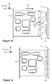
- Fig. 1b shows a plug-in unit 102 of the telecommunications device depicted in Fig. 1a and a detail of the frame 101.
- the plug-in unit 102 there are electric connectors 112, 113, 114, and 115 the contact parts of which make galvanic contacts with the contact parts of electric connectors 116, 117, 118, and 119 in the backplane of the frame when the plug-in unit 102 is inserted in its place along the direction of the arrow 120, i.e. the negative z direction of the coordinate system 150.
- Fig. 1c shows a situation where the plug-in unit 102 has been installed in the frame 101.
- the plug-in unit 102 has an arrangement according to an embodiment of the invention for indicating correct installation of a plug-in unit.
- Said arrangement comprises a distance indicator 106 located at the edge 109 of the plug-in unit and adapted to produce an indication for correct installation of the plug-in unit in response to a situation where the distance of the distance indicator from a wall 107 of the frame 101 is smaller than a predetermined threshold value.
- the distance indicator 106 is an electromechanical limit switch adapted to produce said indication in response to a situation where a first part 110 of said limit switch has contacted the wall 107 of the frame and said first part has travelled a predetermined distance in relation to a second part 111 of said limit switch, which second part is fixed relative to the plug-in unit 102.
- the distance indicator 106 is thus capable of producing said indication without a need for a galvanically conducted electric current between the distance indicator 106 and frame 101.
- Information represented by said indication can be output for example by using an indicator light or some other arrangement perceptible to the installer. It is also possible to feed the information represented by said indication into a network management system, for instance.
- Fig. 2 shows a plug-in unit 202 according to an embodiment of the invention and a detail of a frame 201 of a telecommunications device.
- the plug-in unit may include processor equipment to handle data communications. Said processor equipment may be adapted to support the functionality of at least one of the following, for example: IP (Internet Protocol) router, ATM (Asynchronous Transfer Mode) switch, Ethernet switch, and MPLS (Multi Protocol Label Switching) switch.
- IP Internet Protocol
- ATM Asynchronous Transfer Mode
- Ethernet switch Ethernet switch
- MPLS Multi Protocol Label Switching
- the plug-in unit may also be a power supply unit, for example, in which case it might not include processor equipment to handle data communications.
- the plug-in unit includes distance indicators 206 and 208 which are electromechanical switches located at a distance from each other at opposite ends of the edge 209 of the plug-in unit as shown in Fig. 2 .
- Each distance indicator is adapted to produce an indication for correct installation of the plug-in unit in response to a situation where the distance of the distance indicator from a wall 207 of the frame 201 of said telecommunications device is smaller than a predetermined threshold value.
- the plug-in unit has an electric circuit adapted to indicate correct installation of said plug-in unit if and only if both distance indicators 206 and 208 indicate correct installation of the plug-in unit. It is also possible to have more than two distance indicators in the plug-in unit.
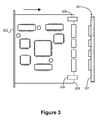
- Fig. 3 shows a plug-in unit 302 according to an embodiment of the invention and a detail of a frame 301 of a telecommunications device.
- the plug-in unit includes distance indicators 306 and 308 which are capacitive distance sensors located at a distance from each other at opposite ends of the edge 309 of the plug-in unit.
- Each distance indicator is adapted to produce an indication for correct installation of the plug-in unit in response to a situation where the distance of the distance indicator from a wall 307 of the frame 301 of said telecommunications device is smaller than a predetermined threshold value.
- the plug-in unit has an electric circuit adapted to indicate correct installation of said plug-in unit if and only if both distance indicators 306 and 308 indicate correct installation of the plug-in unit.
- the distance indicator in the plug-in unit may also be a magnetic distance sensor, distance sensor based on a beam of light or some other distance sensor suitable for the purpose.
- a distance sensor based on a beam of light for instance, need not be located at the edge of the plug-in unit as in the embodiment examples depicted in Figs. 1b, 1c , 2 , and 3 .
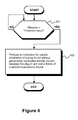
- Fig. 4 shows as a flow diagram a method according to an embodiment of the invention for indicating correct installation of a plug-in unit of a telecommunications device.
- the method includes step 402 to produce an indication, using at least one distance indicator located in said plug-in unit, for correct installation of said plug-in unit if the distance of said distance indicator from a wall of the frame of said telecommunications device is smaller than a predetermined threshold value, condition step 401.
- the distance indicator used in the method is capable of producing said indication without a need for a galvanically conducted electric current between the distance indicator and frame of the telecommunications device.
- the indication is produced by an electromechanical limit switch in response to a situation where the plug-in unit has been pushed towards said wall of the frame of the telecommunications device, a first part of said limit switch has contacted the wall, and said first part has travelled a predetermined distance in relation to a second part of said limit switch, which second part is fixed relative to the plug-in unit.
- the indication is produced using a capacitive distance sensor.
- an indication of correct installation of said plug-in unit is produced if each of the distance indicators, which are located in said plug-in unit at a distance from each other, indicates correct installation of said plug-in unit.
Landscapes
- Engineering & Computer Science (AREA)
- Microelectronics & Electronic Packaging (AREA)
- Details Of Connecting Devices For Male And Female Coupling (AREA)
Applications Claiming Priority (1)
| Application Number | Priority Date | Filing Date | Title |
|---|---|---|---|
| FI20095565A FI20095565A7 (fi) | 2009-05-22 | 2009-05-22 | Menetelmä ja järjestely tietoliikennelaitteen pistoyksikön asennuksen oikeellisuuden ilmaisemiseksi, sekä tietoliikennelaitteen pistoyksikkö |
Publications (3)
| Publication Number | Publication Date |
|---|---|
| EP2254397A2 true EP2254397A2 (de) | 2010-11-24 |
| EP2254397A3 EP2254397A3 (de) | 2016-10-26 |
| EP2254397B1 EP2254397B1 (de) | 2018-02-14 |
Family
ID=40680745
Family Applications (1)
| Application Number | Title | Priority Date | Filing Date |
|---|---|---|---|
| EP10162401.3A Active EP2254397B1 (de) | 2009-05-22 | 2010-05-10 | Verfahren und Anordnung zur Anzeige der korrekten Installation einer einschiebaren Einheit eines Telekommunikations-Geräts |
Country Status (4)
| Country | Link |
|---|---|
| US (1) | US8373426B2 (de) |
| EP (1) | EP2254397B1 (de) |
| CN (1) | CN101895040B (de) |
| FI (1) | FI20095565A7 (de) |
Cited By (3)
| Publication number | Priority date | Publication date | Assignee | Title |
|---|---|---|---|---|
| EP2661163A1 (de) * | 2012-05-03 | 2013-11-06 | Tellabs Oy | Ausrüstung und Steckereinheit der Ausrüstung |
| US9267981B2 (en) | 2012-05-03 | 2016-02-23 | Coriant Oy | Equipment provided with one or more plug-in units |
| US9377500B2 (en) | 2012-05-28 | 2016-06-28 | Coriant Oy | Equipment and a plug-in unit of the equipment |
Families Citing this family (1)
| Publication number | Priority date | Publication date | Assignee | Title |
|---|---|---|---|---|
| US9280920B2 (en) | 2013-04-17 | 2016-03-08 | Lenovo Enterprise Solutions (Singapore) Pte. Ltd. | Status indicating retractable connection label assembly |
Family Cites Families (7)
| Publication number | Priority date | Publication date | Assignee | Title |
|---|---|---|---|---|
| FR2567331B1 (fr) * | 1984-07-09 | 1987-06-26 | Vibrachoc Sa | Dispositif de visualisation de l'enfichage de connecteurs electriques sur un plateau d'aeronef |
| FR2580434B1 (fr) * | 1985-04-12 | 1987-05-15 | Vibrachoc Sa | Dispositif de visualisation de l'enfichage d'un boitier d'equipement electronique sur un plateau d'aeronef |
| US5530302A (en) * | 1994-01-13 | 1996-06-25 | Network Systems Corporation | Circuit module with hot-swap control circuitry |
| JP2954576B1 (ja) * | 1998-06-29 | 1999-09-27 | 三菱電機株式会社 | 挿抜装置及び電子機器システム |
| US7321313B1 (en) * | 2003-07-30 | 2008-01-22 | Tellabs Operations, Inc. | Electronic insertion/extraction cycle counter and logger device |
| JP2007087072A (ja) | 2005-09-21 | 2007-04-05 | Toshiba Corp | 電子機器 |
| JP2008147286A (ja) | 2006-12-07 | 2008-06-26 | Yokogawa Electric Corp | 電子機器 |
-
2009
- 2009-05-22 FI FI20095565A patent/FI20095565A7/fi not_active Application Discontinuation
-
2010
- 2010-05-10 EP EP10162401.3A patent/EP2254397B1/de active Active
- 2010-05-11 US US12/777,291 patent/US8373426B2/en active Active
- 2010-05-14 CN CN201010180920.8A patent/CN101895040B/zh active Active
Non-Patent Citations (1)
| Title |
|---|
| None |
Cited By (4)
| Publication number | Priority date | Publication date | Assignee | Title |
|---|---|---|---|---|
| EP2661163A1 (de) * | 2012-05-03 | 2013-11-06 | Tellabs Oy | Ausrüstung und Steckereinheit der Ausrüstung |
| US9267981B2 (en) | 2012-05-03 | 2016-02-23 | Coriant Oy | Equipment provided with one or more plug-in units |
| US9459306B2 (en) | 2012-05-03 | 2016-10-04 | Coriant Oy | Equipment and a plug-in unit of the equipment |
| US9377500B2 (en) | 2012-05-28 | 2016-06-28 | Coriant Oy | Equipment and a plug-in unit of the equipment |
Also Published As
| Publication number | Publication date |
|---|---|
| US20100295561A1 (en) | 2010-11-25 |
| FI20095565L (fi) | 2010-11-23 |
| FI20095565A0 (fi) | 2009-05-22 |
| EP2254397A3 (de) | 2016-10-26 |
| EP2254397B1 (de) | 2018-02-14 |
| US8373426B2 (en) | 2013-02-12 |
| CN101895040A (zh) | 2010-11-24 |
| CN101895040B (zh) | 2014-10-15 |
| FI20095565A7 (fi) | 2010-11-23 |
Similar Documents
| Publication | Publication Date | Title |
|---|---|---|
| US8197280B2 (en) | Smart cable provisioning for a patch cord management system | |
| US8164907B2 (en) | Communications device having structures for connecting to detachably installable power supply units | |
| US8373426B2 (en) | Method and arrangement for indicating correct installation of plug-in unit of telecommunications device | |
| CN103181030B (zh) | 电气穿墙端子 | |
| CN215911371U (zh) | 数据交换设备、装置 | |
| EP2741519A1 (de) | Telekommunikationseinrichtung | |
| CN103383424B (zh) | 具有一个或多个插接式单元的设备 | |
| ATE279852T1 (de) | Aufbausystem für elektrische flachbaugruppen mit zentrierkontaktteilen an frontelementen und separaten aufnahmekontaktteilen, insbesondere mit kontaktmessern im baugruppenträger | |
| US10825633B2 (en) | Circuit board arrangement having electrical leads for holding an electrical fuse | |
| EP2669691B1 (de) | Ausrüstung und Steckereinheit der Ausrüstung | |
| EP2661163B1 (de) | Ausrüstung und Steckereinheit der Ausrüstung | |
| US20140247618A1 (en) | Electrical device | |
| KR101634125B1 (ko) | 통신장비연결용 판넬 | |
| CN101073129A (zh) | 壳体 | |
| CN215867158U (zh) | 断料检测装置和断料检测电路 | |
| US20120309223A1 (en) | Guide element for a connector device | |
| JP2002151226A (ja) | 端子接続部分の接続確認方法及び同装置 | |
| WO2018146369A1 (en) | A circuit board system and method for manufacturing the same | |
| CN117178639A (zh) | 电气模块和相关联的基架 | |
| CN112946777A (zh) | 一种服务器机柜和数据中心 | |
| CN120065069A (zh) | 电源系统和网络设备 | |
| CN101035000A (zh) | 设置于网络装置中的继电器与相关方法 | |
| ITRM20110011A1 (it) | Modulo di accesso per strisce di sezionamento di permutatori di reti telefoniche. | |
| HK1115473B (en) | Differential Current Converter |
Legal Events
| Date | Code | Title | Description |
|---|---|---|---|
| PUAI | Public reference made under article 153(3) epc to a published international application that has entered the european phase |
Free format text: ORIGINAL CODE: 0009012 |
|
| AK | Designated contracting states |
Kind code of ref document: A2 Designated state(s): AL AT BE BG CH CY CZ DE DK EE ES FI FR GB GR HR HU IE IS IT LI LT LU LV MC MK MT NL NO PL PT RO SE SI SK SM TR |
|
| AX | Request for extension of the european patent |
Extension state: BA ME RS |
|
| RAP1 | Party data changed (applicant data changed or rights of an application transferred) |
Owner name: CORIANT OY |
|
| PUAL | Search report despatched |
Free format text: ORIGINAL CODE: 0009013 |
|
| AK | Designated contracting states |
Kind code of ref document: A3 Designated state(s): AL AT BE BG CH CY CZ DE DK EE ES FI FR GB GR HR HU IE IS IT LI LT LU LV MC MK MT NL NO PL PT RO SE SI SK SM TR |
|
| AX | Request for extension of the european patent |
Extension state: BA ME RS |
|
| RIC1 | Information provided on ipc code assigned before grant |
Ipc: H05K 7/14 20060101AFI20160921BHEP |
|
| 17P | Request for examination filed |
Effective date: 20170421 |
|
| RBV | Designated contracting states (corrected) |
Designated state(s): AL AT BE BG CH CY CZ DE DK EE ES FI FR GB GR HR HU IE IS IT LI LT LU LV MC MK MT NL NO PL PT RO SE SI SK SM TR |
|
| GRAP | Despatch of communication of intention to grant a patent |
Free format text: ORIGINAL CODE: EPIDOSNIGR1 |
|
| INTG | Intention to grant announced |
Effective date: 20170915 |
|
| GRAS | Grant fee paid |
Free format text: ORIGINAL CODE: EPIDOSNIGR3 |
|
| GRAA | (expected) grant |
Free format text: ORIGINAL CODE: 0009210 |
|
| AK | Designated contracting states |
Kind code of ref document: B1 Designated state(s): AL AT BE BG CH CY CZ DE DK EE ES FI FR GB GR HR HU IE IS IT LI LT LU LV MC MK MT NL NO PL PT RO SE SI SK SM TR |
|
| REG | Reference to a national code |
Ref country code: GB Ref legal event code: FG4D |
|
| REG | Reference to a national code |
Ref country code: CH Ref legal event code: EP |
|
| REG | Reference to a national code |
Ref country code: IE Ref legal event code: FG4D |
|
| REG | Reference to a national code |
Ref country code: DE Ref legal event code: R096 Ref document number: 602010048447 Country of ref document: DE Ref country code: AT Ref legal event code: REF Ref document number: 970676 Country of ref document: AT Kind code of ref document: T Effective date: 20180315 |
|
| REG | Reference to a national code |
Ref country code: FR Ref legal event code: PLFP Year of fee payment: 9 |
|
| REG | Reference to a national code |
Ref country code: NL Ref legal event code: MP Effective date: 20180214 |
|
| REG | Reference to a national code |
Ref country code: AT Ref legal event code: MK05 Ref document number: 970676 Country of ref document: AT Kind code of ref document: T Effective date: 20180214 |
|
| PG25 | Lapsed in a contracting state [announced via postgrant information from national office to epo] |
Ref country code: CY Free format text: LAPSE BECAUSE OF FAILURE TO SUBMIT A TRANSLATION OF THE DESCRIPTION OR TO PAY THE FEE WITHIN THE PRESCRIBED TIME-LIMIT Effective date: 20180214 Ref country code: HR Free format text: LAPSE BECAUSE OF FAILURE TO SUBMIT A TRANSLATION OF THE DESCRIPTION OR TO PAY THE FEE WITHIN THE PRESCRIBED TIME-LIMIT Effective date: 20180214 Ref country code: NL Free format text: LAPSE BECAUSE OF FAILURE TO SUBMIT A TRANSLATION OF THE DESCRIPTION OR TO PAY THE FEE WITHIN THE PRESCRIBED TIME-LIMIT Effective date: 20180214 Ref country code: LT Free format text: LAPSE BECAUSE OF FAILURE TO SUBMIT A TRANSLATION OF THE DESCRIPTION OR TO PAY THE FEE WITHIN THE PRESCRIBED TIME-LIMIT Effective date: 20180214 Ref country code: ES Free format text: LAPSE BECAUSE OF FAILURE TO SUBMIT A TRANSLATION OF THE DESCRIPTION OR TO PAY THE FEE WITHIN THE PRESCRIBED TIME-LIMIT Effective date: 20180214 Ref country code: FI Free format text: LAPSE BECAUSE OF FAILURE TO SUBMIT A TRANSLATION OF THE DESCRIPTION OR TO PAY THE FEE WITHIN THE PRESCRIBED TIME-LIMIT Effective date: 20180214 Ref country code: NO Free format text: LAPSE BECAUSE OF FAILURE TO SUBMIT A TRANSLATION OF THE DESCRIPTION OR TO PAY THE FEE WITHIN THE PRESCRIBED TIME-LIMIT Effective date: 20180514 |
|
| PG25 | Lapsed in a contracting state [announced via postgrant information from national office to epo] |
Ref country code: BG Free format text: LAPSE BECAUSE OF FAILURE TO SUBMIT A TRANSLATION OF THE DESCRIPTION OR TO PAY THE FEE WITHIN THE PRESCRIBED TIME-LIMIT Effective date: 20180514 Ref country code: SE Free format text: LAPSE BECAUSE OF FAILURE TO SUBMIT A TRANSLATION OF THE DESCRIPTION OR TO PAY THE FEE WITHIN THE PRESCRIBED TIME-LIMIT Effective date: 20180214 Ref country code: LV Free format text: LAPSE BECAUSE OF FAILURE TO SUBMIT A TRANSLATION OF THE DESCRIPTION OR TO PAY THE FEE WITHIN THE PRESCRIBED TIME-LIMIT Effective date: 20180214 Ref country code: AT Free format text: LAPSE BECAUSE OF FAILURE TO SUBMIT A TRANSLATION OF THE DESCRIPTION OR TO PAY THE FEE WITHIN THE PRESCRIBED TIME-LIMIT Effective date: 20180214 Ref country code: GR Free format text: LAPSE BECAUSE OF FAILURE TO SUBMIT A TRANSLATION OF THE DESCRIPTION OR TO PAY THE FEE WITHIN THE PRESCRIBED TIME-LIMIT Effective date: 20180515 |
|
| PGFP | Annual fee paid to national office [announced via postgrant information from national office to epo] |
Ref country code: FR Payment date: 20180522 Year of fee payment: 9 |
|
| PG25 | Lapsed in a contracting state [announced via postgrant information from national office to epo] |
Ref country code: PL Free format text: LAPSE BECAUSE OF FAILURE TO SUBMIT A TRANSLATION OF THE DESCRIPTION OR TO PAY THE FEE WITHIN THE PRESCRIBED TIME-LIMIT Effective date: 20180214 Ref country code: EE Free format text: LAPSE BECAUSE OF FAILURE TO SUBMIT A TRANSLATION OF THE DESCRIPTION OR TO PAY THE FEE WITHIN THE PRESCRIBED TIME-LIMIT Effective date: 20180214 Ref country code: RO Free format text: LAPSE BECAUSE OF FAILURE TO SUBMIT A TRANSLATION OF THE DESCRIPTION OR TO PAY THE FEE WITHIN THE PRESCRIBED TIME-LIMIT Effective date: 20180214 Ref country code: AL Free format text: LAPSE BECAUSE OF FAILURE TO SUBMIT A TRANSLATION OF THE DESCRIPTION OR TO PAY THE FEE WITHIN THE PRESCRIBED TIME-LIMIT Effective date: 20180214 Ref country code: IT Free format text: LAPSE BECAUSE OF FAILURE TO SUBMIT A TRANSLATION OF THE DESCRIPTION OR TO PAY THE FEE WITHIN THE PRESCRIBED TIME-LIMIT Effective date: 20180214 |
|
| REG | Reference to a national code |
Ref country code: DE Ref legal event code: R097 Ref document number: 602010048447 Country of ref document: DE |
|
| PG25 | Lapsed in a contracting state [announced via postgrant information from national office to epo] |
Ref country code: SM Free format text: LAPSE BECAUSE OF FAILURE TO SUBMIT A TRANSLATION OF THE DESCRIPTION OR TO PAY THE FEE WITHIN THE PRESCRIBED TIME-LIMIT Effective date: 20180214 Ref country code: DK Free format text: LAPSE BECAUSE OF FAILURE TO SUBMIT A TRANSLATION OF THE DESCRIPTION OR TO PAY THE FEE WITHIN THE PRESCRIBED TIME-LIMIT Effective date: 20180214 Ref country code: SK Free format text: LAPSE BECAUSE OF FAILURE TO SUBMIT A TRANSLATION OF THE DESCRIPTION OR TO PAY THE FEE WITHIN THE PRESCRIBED TIME-LIMIT Effective date: 20180214 Ref country code: CZ Free format text: LAPSE BECAUSE OF FAILURE TO SUBMIT A TRANSLATION OF THE DESCRIPTION OR TO PAY THE FEE WITHIN THE PRESCRIBED TIME-LIMIT Effective date: 20180214 |
|
| REG | Reference to a national code |
Ref country code: CH Ref legal event code: PL |
|
| PLBE | No opposition filed within time limit |
Free format text: ORIGINAL CODE: 0009261 |
|
| STAA | Information on the status of an ep patent application or granted ep patent |
Free format text: STATUS: NO OPPOSITION FILED WITHIN TIME LIMIT |
|
| 26N | No opposition filed |
Effective date: 20181115 |
|
| GBPC | Gb: european patent ceased through non-payment of renewal fee |
Effective date: 20180514 |
|
| REG | Reference to a national code |
Ref country code: BE Ref legal event code: MM Effective date: 20180531 |
|
| PG25 | Lapsed in a contracting state [announced via postgrant information from national office to epo] |
Ref country code: MC Free format text: LAPSE BECAUSE OF FAILURE TO SUBMIT A TRANSLATION OF THE DESCRIPTION OR TO PAY THE FEE WITHIN THE PRESCRIBED TIME-LIMIT Effective date: 20180214 |
|
| REG | Reference to a national code |
Ref country code: IE Ref legal event code: MM4A |
|
| PG25 | Lapsed in a contracting state [announced via postgrant information from national office to epo] |
Ref country code: LI Free format text: LAPSE BECAUSE OF NON-PAYMENT OF DUE FEES Effective date: 20180531 Ref country code: SI Free format text: LAPSE BECAUSE OF FAILURE TO SUBMIT A TRANSLATION OF THE DESCRIPTION OR TO PAY THE FEE WITHIN THE PRESCRIBED TIME-LIMIT Effective date: 20180214 Ref country code: CH Free format text: LAPSE BECAUSE OF NON-PAYMENT OF DUE FEES Effective date: 20180531 |
|
| PG25 | Lapsed in a contracting state [announced via postgrant information from national office to epo] |
Ref country code: LU Free format text: LAPSE BECAUSE OF NON-PAYMENT OF DUE FEES Effective date: 20180510 |
|
| PG25 | Lapsed in a contracting state [announced via postgrant information from national office to epo] |
Ref country code: GB Free format text: LAPSE BECAUSE OF NON-PAYMENT OF DUE FEES Effective date: 20180514 Ref country code: IE Free format text: LAPSE BECAUSE OF NON-PAYMENT OF DUE FEES Effective date: 20180510 |
|
| PG25 | Lapsed in a contracting state [announced via postgrant information from national office to epo] |
Ref country code: BE Free format text: LAPSE BECAUSE OF NON-PAYMENT OF DUE FEES Effective date: 20180531 |
|
| PG25 | Lapsed in a contracting state [announced via postgrant information from national office to epo] |
Ref country code: MT Free format text: LAPSE BECAUSE OF NON-PAYMENT OF DUE FEES Effective date: 20180510 |
|
| PG25 | Lapsed in a contracting state [announced via postgrant information from national office to epo] |
Ref country code: TR Free format text: LAPSE BECAUSE OF FAILURE TO SUBMIT A TRANSLATION OF THE DESCRIPTION OR TO PAY THE FEE WITHIN THE PRESCRIBED TIME-LIMIT Effective date: 20180214 |
|
| PG25 | Lapsed in a contracting state [announced via postgrant information from national office to epo] |
Ref country code: PT Free format text: LAPSE BECAUSE OF FAILURE TO SUBMIT A TRANSLATION OF THE DESCRIPTION OR TO PAY THE FEE WITHIN THE PRESCRIBED TIME-LIMIT Effective date: 20180214 Ref country code: HU Free format text: LAPSE BECAUSE OF FAILURE TO SUBMIT A TRANSLATION OF THE DESCRIPTION OR TO PAY THE FEE WITHIN THE PRESCRIBED TIME-LIMIT; INVALID AB INITIO Effective date: 20100510 |
|
| PG25 | Lapsed in a contracting state [announced via postgrant information from national office to epo] |
Ref country code: FR Free format text: LAPSE BECAUSE OF NON-PAYMENT OF DUE FEES Effective date: 20190531 Ref country code: MK Free format text: LAPSE BECAUSE OF NON-PAYMENT OF DUE FEES Effective date: 20180214 |
|
| PG25 | Lapsed in a contracting state [announced via postgrant information from national office to epo] |
Ref country code: IS Free format text: LAPSE BECAUSE OF FAILURE TO SUBMIT A TRANSLATION OF THE DESCRIPTION OR TO PAY THE FEE WITHIN THE PRESCRIBED TIME-LIMIT Effective date: 20180614 |
|
| PGFP | Annual fee paid to national office [announced via postgrant information from national office to epo] |
Ref country code: DE Payment date: 20250521 Year of fee payment: 16 |