EP2254332A2 - Verteilte Netzwerkleistungsüberwachung - Google Patents
Verteilte Netzwerkleistungsüberwachung Download PDFInfo
- Publication number
- EP2254332A2 EP2254332A2 EP20100162738 EP10162738A EP2254332A2 EP 2254332 A2 EP2254332 A2 EP 2254332A2 EP 20100162738 EP20100162738 EP 20100162738 EP 10162738 A EP10162738 A EP 10162738A EP 2254332 A2 EP2254332 A2 EP 2254332A2
- Authority
- EP
- European Patent Office
- Prior art keywords
- monitoring
- results
- processor
- cable
- downstream frequency
- Prior art date
- Legal status (The legal status is an assumption and is not a legal conclusion. Google has not performed a legal analysis and makes no representation as to the accuracy of the status listed.)
- Withdrawn
Links
- 238000012544 monitoring process Methods 0.000 title claims abstract description 111
- 239000000523 sample Substances 0.000 claims abstract description 139
- 238000004891 communication Methods 0.000 claims abstract description 84
- 238000011144 upstream manufacturing Methods 0.000 claims abstract description 35
- 238000005259 measurement Methods 0.000 claims description 19
- 238000000034 method Methods 0.000 claims description 7
- 238000012937 correction Methods 0.000 claims description 6
- 230000004044 response Effects 0.000 claims description 5
- 230000002035 prolonged effect Effects 0.000 abstract description 5
- 230000015654 memory Effects 0.000 description 32
- 230000000875 corresponding effect Effects 0.000 description 18
- 238000010586 diagram Methods 0.000 description 16
- 238000004458 analytical method Methods 0.000 description 11
- 230000008859 change Effects 0.000 description 5
- 239000000835 fiber Substances 0.000 description 4
- 230000005540 biological transmission Effects 0.000 description 3
- 230000015556 catabolic process Effects 0.000 description 3
- 238000006731 degradation reaction Methods 0.000 description 3
- 238000012986 modification Methods 0.000 description 3
- 230000004048 modification Effects 0.000 description 3
- 101001091379 Homo sapiens Kallikrein-5 Proteins 0.000 description 2
- 102100034868 Kallikrein-5 Human genes 0.000 description 2
- 108700026140 MAC combination Proteins 0.000 description 2
- 239000000969 carrier Substances 0.000 description 2
- 238000012790 confirmation Methods 0.000 description 2
- 230000001419 dependent effect Effects 0.000 description 2
- 238000013461 design Methods 0.000 description 2
- 230000000694 effects Effects 0.000 description 2
- 239000000284 extract Substances 0.000 description 2
- 230000008569 process Effects 0.000 description 2
- 238000001228 spectrum Methods 0.000 description 2
- 230000009885 systemic effect Effects 0.000 description 2
- 239000004606 Fillers/Extenders Substances 0.000 description 1
- 230000009471 action Effects 0.000 description 1
- 238000006243 chemical reaction Methods 0.000 description 1
- 239000012141 concentrate Substances 0.000 description 1
- 230000008878 coupling Effects 0.000 description 1
- 238000010168 coupling process Methods 0.000 description 1
- 238000005859 coupling reaction Methods 0.000 description 1
- 238000007405 data analysis Methods 0.000 description 1
- 238000001514 detection method Methods 0.000 description 1
- 238000005538 encapsulation Methods 0.000 description 1
- 238000011156 evaluation Methods 0.000 description 1
- 230000006870 function Effects 0.000 description 1
- 238000009434 installation Methods 0.000 description 1
- 230000007774 longterm Effects 0.000 description 1
- 230000007257 malfunction Effects 0.000 description 1
- 230000000737 periodic effect Effects 0.000 description 1
- 238000012545 processing Methods 0.000 description 1
- 238000013139 quantization Methods 0.000 description 1
- 238000012360 testing method Methods 0.000 description 1
Images




Classifications
-
- H—ELECTRICITY
- H04—ELECTRIC COMMUNICATION TECHNIQUE
- H04N—PICTORIAL COMMUNICATION, e.g. TELEVISION
- H04N17/00—Diagnosis, testing or measuring for television systems or their details
- H04N17/004—Diagnosis, testing or measuring for television systems or their details for digital television systems
-
- H—ELECTRICITY
- H04—ELECTRIC COMMUNICATION TECHNIQUE
- H04N—PICTORIAL COMMUNICATION, e.g. TELEVISION
- H04N7/00—Television systems
- H04N7/10—Adaptations for transmission by electrical cable
- H04N7/102—Circuits therefor, e.g. noise reducers, equalisers, amplifiers
- H04N7/104—Switchers or splitters
-
- H—ELECTRICITY
- H04—ELECTRIC COMMUNICATION TECHNIQUE
- H04N—PICTORIAL COMMUNICATION, e.g. TELEVISION
- H04N21/00—Selective content distribution, e.g. interactive television or video on demand [VOD]
- H04N21/60—Network structure or processes for video distribution between server and client or between remote clients; Control signalling between clients, server and network components; Transmission of management data between server and client, e.g. sending from server to client commands for recording incoming content stream; Communication details between server and client
- H04N21/61—Network physical structure; Signal processing
- H04N21/6106—Network physical structure; Signal processing specially adapted to the downstream path of the transmission network
- H04N21/6118—Network physical structure; Signal processing specially adapted to the downstream path of the transmission network involving cable transmission, e.g. using a cable modem
-
- H—ELECTRICITY
- H04—ELECTRIC COMMUNICATION TECHNIQUE
- H04N—PICTORIAL COMMUNICATION, e.g. TELEVISION
- H04N21/00—Selective content distribution, e.g. interactive television or video on demand [VOD]
- H04N21/60—Network structure or processes for video distribution between server and client or between remote clients; Control signalling between clients, server and network components; Transmission of management data between server and client, e.g. sending from server to client commands for recording incoming content stream; Communication details between server and client
- H04N21/61—Network physical structure; Signal processing
- H04N21/6156—Network physical structure; Signal processing specially adapted to the upstream path of the transmission network
- H04N21/6168—Network physical structure; Signal processing specially adapted to the upstream path of the transmission network involving cable transmission, e.g. using a cable modem
-
- H—ELECTRICITY
- H04—ELECTRIC COMMUNICATION TECHNIQUE
- H04N—PICTORIAL COMMUNICATION, e.g. TELEVISION
- H04N21/00—Selective content distribution, e.g. interactive television or video on demand [VOD]
- H04N21/60—Network structure or processes for video distribution between server and client or between remote clients; Control signalling between clients, server and network components; Transmission of management data between server and client, e.g. sending from server to client commands for recording incoming content stream; Communication details between server and client
- H04N21/63—Control signaling related to video distribution between client, server and network components; Network processes for video distribution between server and clients or between remote clients, e.g. transmitting basic layer and enhancement layers over different transmission paths, setting up a peer-to-peer communication via Internet between remote STB's; Communication protocols; Addressing
- H04N21/647—Control signaling between network components and server or clients; Network processes for video distribution between server and clients, e.g. controlling the quality of the video stream, by dropping packets, protecting content from unauthorised alteration within the network, monitoring of network load, bridging between two different networks, e.g. between IP and wireless
- H04N21/64723—Monitoring of network processes or resources, e.g. monitoring of network load
Definitions
- FIG. 1 is a block diagram showing an example of such a network.
- a national head end may include elements such as VOD servers, servers for receiving and encapsulating programming content, management servers, etc.
- the national head end communicates with multiple regional head ends over a national backbone network, with the regional head ends also including facilities for VOD and programming reception/encapsulation.
- Each regional head end communicates over a regional access network with multiple hubs.
- Each hub includes a cable modem termination system (CMTS), devices for quadrature amplitude modulation/demodulation (QAM), and other elements.
- CMTS cable modem termination system
- QAM quadrature amplitude modulation/demodulation
- the fiber optic portion of the HFC access network includes multiple nodes on a fiber optic ring.
- the coaxial portion of the HFC access network includes coaxial feeder lines extending from those nodes. Drop coaxial cables extend from taps in the feeder cables and connect to the subscriber premises. Amplifiers are distributed along the coaxial feeder cables. Alternating current (AC) power may also be input into the feeder cables so as to provide a power source for the amplifiers.
- FIG. 1 only shows a very small part of the coaxial portion of an HFC network associated with a single hub. In actuality, the coaxial cable plants associated with hubs may be the largest part of the system, and there may be many subscribers receiving service through a particular hub.
- Communication through a coaxial cable can be affected in many ways.
- temperature changes can affect signal quality in coaxial cables.
- signal quality measurements from the coaxial part of an HFC network can be very useful.
- Existing test equipment is relatively expensive, and in many cases a field service technician must be dispatched to take measurements.
- Some set top boxes and cable modems can measure certain signal parameters, but only over a few channels at a time and at relatively infrequent intervals.
- signal measurements from inside a subscriber premises may not be indicative of a network problem. For example, signal degradation within a subscriber location could be affected by a splitter or other subscriber-installed component and not by a systemic network condition.
- a probe that can be installed in a desired location in an access network.
- a probe can be installed in a coaxial cable plant of an access network.
- the probe is configured to monitor one or more communication parameters on one or more downstream frequency channels carried on a physical medium such as a coaxial cable. Results of repeated monitoring are stored over a predetermined period. At the conclusion of the monitoring period, data reports reflecting the stored results are transmitted in upstream frequency channels carried on the same medium.
- the probe can also be configured to send immediate messages if a parameter exceeds predefined limits.
- the probe can store a plurality of monitoring programs and can be reprogrammed remotely.
- the probe is contained within a cable tap. Numerous probes can be deployed throughout a coaxial cable plant so as to provide monitoring data from each of many locations over a prolonged period.
- coaxial cable plant refers to the portion of an access network that transmits signals over coaxial cable.
- Some of the parameters measured by the probes are indicative of signal quality in the coaxial cable plant (e.g., RF signal level, modulation error ratio, etc.).
- Some parameters are indicative of whether a particular data payload (e.g., data for one or more programming services such as HBO, ESPN, etc.; a specific advertisement; a governmentally-required emergency message; etc.) has been transmitted.
- Each probe is coupled to a coaxial cable, monitors signals on that cable, and reports monitoring data upstream over the same coaxial cable.
- the probes in at least some embodiments are relatively inexpensive and automated, they can be widely deployed and provide data over prolonged periods of time.
- the probes can also be remotely controlled and/or reprogrammed to provide specific data when needed.
- the probes are sized and configured for attachment to one of the drop outputs of a cable tap. In other embodiments, the probes are housed within a tap.
- coaxial cable carries communications in frequencies that may be as low as 5 MHz and as high as 1002 MHZ (or higher).
- frequency channels in the lower portion of the available frequency spectrum are used to carry upstream communications from subscriber devices to the hub.
- Higher frequency channels are used to carry downstream communications from the hub to subscriber devices.
- the downstream frequency channels usually have bandwidths of 6 MHz or 8 MHz, although upstream channels may use narrower bands.
- most upstream and downstream communications with a subscriber device over a coaxial cable are in accordance with the set of standards known as
- DOCSIS Data over Cable Service Interface Specifications
- downstream 6 MHz or 8 MHz channels can be distributed between 108 MHz and 1002 MHz and upstream channels are located between 5 MHz and 42 (or 85) MHz. Frequency channels between these two regions are used for non-DOCSIS communications (e.g., legacy analog CATV programming).
- Upstream frequency channels and at least the downstream frequency channels above 108 MHz are typically modulated using quadrature amplitude modulation (QAM).
- QAM quadrature amplitude modulation
- Downstream frequency channels can be used to communicate many types of data.
- some downstream channels may be used to send generic user data payloads (e.g., data from an Internet site to which a subscriber has navigated, an email, a downloaded file, etc.) to a subscriber cable modem (CM) for further communication to a home computer.
- CM subscriber cable modem
- some downstream channels may be used to transmit digital video data payloads to a subscriber set top box (STB) for ultimate display on a television.
- STB subscriber set top box
- Some channels may transmit several types of data by, e.g., interspersing packets containing digital video with packets containing generic user data.
- MPEG Moving Picture Expert Group
- PID packet identifier
- MAC media access control
- FIG. 2 is a block diagram of a monitoring probe 10 according to at least some embodiments.
- Probe 10 connects to a coaxial cable over a hardware interface 11.
- hardware interface 11 is a standard coaxial cable coupler that can be directly connected to a drop output of a cable tap.
- probe 10 is part of a coaxial cable tap and monitors downstream frequency channels carried by a feeder coaxial cable connected to a forward RF input of the tap.
- Hardware interface 11 is connected to a diplexer 12 that allows downstream signals to pass into probe 10 and upstream signals to pass out of probe 10.
- Downstream signals flow from diplexer 12 to a wideband tuner 14.
- tuner 14 forwards a signal for the tuned frequency channel.
- tuner 14 is a single wideband tuner that is able to selectively tune to any frequency channel between 108 MHz and 1002 MHz.
- tuner 14 is able to tune to channels below 108 MHz and/or above 1002 MHz.
- tuner 14 can be replaced with multiple tuners that tune across narrower bands.
- main processor 15 is a single application specific integrated circuit (ASIC) having signal analysis circuits and programmable logic for performing operations as described herein. These circuits and logic are represented by functional blocks 16 through 18 for purposes of explanation. Controller 16 contains logic for executing instructions that control the operation of main processor 15 and tuner 14. Controller 16 also executes instructions to perform more advanced signal and/or data analysis. For example, and as described below, controller 16 is in some embodiments configured to examine specific data fields within a MPEG transport packet or a digital video payload packet and determine if specific packets have been received. In addition to hardwired instructions, controller 16 reads instructions stored in one or more memories 19 or 20 and executes those instructions.
- ASIC application specific integrated circuit
- Memories 19 and 20 may include non-volatile read-only memory (ROM), volatile random access memory (RAM) and non-volatile read/write memory (e.g., FLASH memory).
- ROM read-only memory
- RAM volatile random access memory
- FLASH memory non-volatile read/write memory
- Fully and/or partially programmable microprocessor circuits for performing the herein-described operations of controller 16 (and other portions of main processor 15) are either known in the art or can be readily constructed by persons of ordinary skill in the art once such persons are provided with the information contained herein.
- the tuner 14, diplexer 12 and/or memory 20 may be included on the same ASIC chip with main processor 15.
- the signal from tuner 14 is initially processed by DOCSIS PHY/MAC sub-processor 17.
- SUB-processor 17 includes a demodulator and processes the QAM physical (PHY) and DOCSIS media access control (MAC) layers.
- DOCSIS PHY/MAC sub-processor 17 demodulates QAM signals, performs forward error correction (FEC) decoding and deinterleaving, reads MPEG transport stream headers to identify packets as DOCSIS MAC packets or digital video packets, extracts DOCSIS MAC payloads from MPEG packets containing DOCSIS MAC payloads, reads MAC headers and MAC management messages, etc.
- FEC forward error correction
- DOCSIS PHY/MAC sub-processor 17 With regard to upstream communications from probe 10, DOCSIS PHY/MAC sub-processor 17 generates MAC management messages according to the DOCSIS MAC protocol, encapsulates data for transmission upstream according to the DOCSIS MAC protocol, performs error correction coding and interleaving, performs QAM modulation, etc.
- DOCSIS PHY and MAC operations that are performed by a DOCSIS-compliant subscriber device are defined by the applicable DOCSIS standards, including but not limited to the following: DOCSIS 3.0 Physical Layer Specification (CM-SP-PHYv3.0-I07-080522); DOCSIS 3.0 MAC and Upper Layer Protocols Interface Specification (CM-SP-MULPIv3.0-I08-080522); and Downstream RF Interface Specification (CM-SP-DRFI-I06-080215).
- DOCSIS PHY/MAC sub-processor 17 is configured to perform all PHY and MAC operations that a conventional DOCSIS-compliant CM or STB can perform.
- DOCSIS PHY/MAC sub-processor 17 measures some of the signal quality and other communications parameters, discussed in more detail below, for the tuned frequency channel. Sub-processor 17 then communicates these measurements and other data to controller 16 so that controller 16 may, e.g., store such data in memory 19 and/or memory 20 for additional analysis and/or later communication upstream. As represented by the double-headed arrow connecting blocks 16 and 17, sub-processor 17 also receives data and control signals from controller 16.
- the control signals and data sent to sub-processor 17 by controller 16 could include instructions to provide certain data or signal measurements, data and instructions to transmit that data in an upstream message, etc.
- DOCSIS PHY/MAC sub-processor 17 also outputs a demodulated signal for additional analysis in signal analysis sub-processor 18, which includes additional circuits and logic for performing analyses to obtain desired data about downstream signals.
- signal analysis sub-processor 18 may in some embodiments be dedicated to certain types of signal measurements that fall outside of normal DOCSIS PHY/MAC processing. Measurements and other data from signal analysis sub-processor 18 are provided to controller 16, which may store such measurements and data in memory 19 or memory 20 for additional analysis and/or later communication upstream.
- main processor 15 In addition to receiving and analyzing downstream communications, main processor 15 sends reporting data and other communications upstream. Examples of such upstream communications, which pass from main processor 15 to diplexer 12 and hardware interface 11, are described below.
- probe 10 includes a power supply circuit 23 that provides electrical operating power to main processor 15 and tuner 14.
- Power supply circuit 23 receives input power from a power source and converts that power to an appropriate form for main processor 15 and tuner 14. Power supply and conversion circuits are known in the art and thus are not further described herein. In some embodiments, and as explained below, circuit 23 receives input power from the AC power supplied in a coaxial feeder cable. In other embodiments, a probe power supply circuit may receive incoming power from a battery, from a conventional AC line source, or from some other source.
- Probe 10 is configurable to measure or otherwise evaluate numerous signal, data and other communication parameters. Examples of such parameters are provided below. Circuits and logic for analyzing signals and data to measure or otherwise evaluate such parameters are known in the art or would be readily apparent to persons of ordinary skill in the art in view of the description provided herein.
- probe 10 is configured to monitor RF signal level on all downstream QAM channels on a regular basis.
- RF signal strength in a coaxial cable plant is typically measured in decibel millivolts (dBmV), with 0 dBmV defined to represent a 1 mV signal on a 75 Ohm cable.
- RF signal level data can be extremely useful in many situations.
- cable modems can tolerate an input signal between - 15 dBmV and +15 dBmV, but performance is not uniform over this range. Optimal performance is often realized with input RF levels held between -6 dBmV to +15 dBmV.
- Coaxial cable attenuates higher frequency carriers less than lower frequency carriers. So as to attain the correct signal level at the subscriber premises, coaxial feeder amplifiers and fiber nodes have both upstream and downstream PADs (passive attenuation devices) and equalizers to adjust signal level in different frequency ranges.
- PADs passive attenuation devices
- directional couplers and taps in the coaxial cable plant can also be chosen so as to have directional split and tap values that help keep the signal level reaching a subscriber premises at the correct level.
- Obtaining repeated RF signal levels on multiple frequency channels, from numerous locations in a coaxial cable plant, and over a prolonged period can provide data that is extremely useful for adjustment of PADs and equalizers and for adding (or replacing) taps, couplers, splitters and other components in the coaxial plant.
- Additional parameters that can be measured by probe 10 for some or all channels include modulation error ratio (MER), FEC codeword error rate, signal to noise ratio (SNR), PLL lock, quantization noise (QN), and center frequency variation.
- MER measures cluster variance (in dB) caused by a transmit waveform. MER includes effects of intersymbol interference, phase noise other transmitter degradations.
- FEC codeword error rate represents a ratio of the number of uncorrectable code words to the total number of code words sent without errors, with corrected errors and with uncorrectable errors.
- SNR which represents the ratio (in dB) of usable signal to noise, can be defined and measured in any of various ways that are known in the art.
- PLL (phased lock loop) lock is a measurement of the ability of probe 10 to lock onto a carrier frequency for a given channel.
- QN represents is a measure of the relative noise figure when modulating a carrier.
- Center frequency variation represents the amount by which a particular frequency channel has varied from its assigned location in the downstream spectrum.
- the above parameters are only some of the parameters that can be monitored by probe 10 according to various embodiments.
- Other examples of parameters that can be monitored by probe 10 include bit error rate (BER), the percentage of bits that have errors relative to the total number of bits received, and carrier-to-noise ratio (CNR), a ratio of signal power to noise power in the defined measurement bandwidth.
- BER bit error rate
- CNR carrier-to-noise ratio
- Still another example includes errors in the program clock reference (PCR) in digital video MPEG packet streams which are measured by DOCSIS PHY/MAC sub-processor 17.
- probe 10 is also configurable to monitor the QAM constellation on a selected channel and to send a report providing a snapshot of the constellation.
- probe 10 is configured to compare a QAM constellation snapshot to a pattern stored in memory 20 and to report if the snapshot varies from the pattern by a predetermined amount.
- probe 10 may also be configurable to monitor payload-specific communication parameters.
- MPEG video packets can be examined to determine if digital watermarks or other data is present. In this manner, probe 10 can determine if particular content (e.g., an advertisement) has been broadcast.
- a cable company may sell advertising directed to localized markets. Content monitoring by multiple probes 10 located throughout coaxial plant portions of a cable system can provide data to confirm that advertising was broadcast at desired times, on the desired channel(s), and in the desired locations.
- a probe may be further configured to record selected MPEG frames (e.g., selected I-frames and/or P-Frames) to provide additional confirmation of advertisement transmission. In such cases these frames could be recorded within probe 10 and transmitted upstream to a central server or other location for storage. Subsequently, an operator could spot check the stored frames to ensure that such frames were detected and recorded at the appropriate time as required by the advertisement.
- selected MPEG frames e.g., selected I-frames and/or P-Frames
- probe 10 could also be configured to monitor DOCSIS set-top gateway (DSG) data and confirm that the proper services are being transmitted on the proper channels.
- DSG DOCSIS set-top gateway
- DOCSIS PHY/MAC sub-processor 17 could receive and decode DSG tunnels and extract payload data (e.g., SCTE 65 system information, SCTE 18 emergency alerts, etc.) to verify that such data has been sent and received within the plant.
- payload data e.g., SCTE 65 system information, SCTE 18 emergency alerts, etc.
- probe 10 could be configured to monitor the MPEG layer integrity of digital video and detect dropped packets, macroblocking (also known as “tiling") and other types of service degradation. Additionally, probe 10 could monitor program clock reference (PCR) stamps to ensure completeness of programs, monitor program identifiers (PIDs) to ensure continuity, and monitor other MPEG-specific information to ensure correct transmission of video streams.
- PCR program clock reference
- PIDs monitor program identifiers
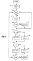
- FIG. 6 is a flow chart for an algorithm of a program by which controller 16 monitors various communication parameters and stores results of that monitoring for later reporting.
- FIG. 6 is merely one example of an algorithm by which controller 16 might operate. Numerous other algorithms are performed in other embodiments. Indeed, and as explained below, probe 10 may store multiple different programs and may change programs in response to commands or upon occurrence of certain conditions.
- the algorithm of FIG. 6 begins at the Start/Reset block and continues to block 200.
- controller 16 initializes variables to be used in the program.
- the "CHAN" variable has values corresponding to monitored downstream frequency channels.
- the variable "PARAM" has values corresponding to parameters monitored by probe 10.
- FIG. 8 is an example of a program data table 400 showing channels and parameters monitored (or monitorable) by probe 10 according to at least some embodiments.
- the actual number of monitored channels will depend on the configuration of a particular network and/or on the programming of probe 10. In some cases, 10 or more channels will be monitored as part of a monitoring program. However, the number of channels on which parameters are monitored during execution of a given program could exceed 20, 50, or more channels. In some embodiments, all channels in the plant could be monitored.
- the cells in the next column of table 400 contain data that is used by controller 16 to identify the center frequency (CF) and bandwidth (BW) for the channels on the corresponding rows.
- center frequency values are shown generically as "F” with a subscript matching the value of the CHAN variable on the same row.
- bandwidth values are shown generically as "B” with a subscript matching the CHAN variable value of the CHAN variable on the same row.
- many of the channels will have the same value for B (e.g., 6 MHz for a DOCSIS downstream channel).
- values for F and B can be reprogrammed so as to change monitored channels.
- a null value e.g., all 0-bits
- for the F and/or B variable(s) could be used to indicate that a channel is the last in the list.
- Each of the remaining columns of table 400 corresponds to a different one of the communication parameters that can be monitored by probe 10.
- probe 10 is configurable to monitor an arbitrary number p of communication parameters.
- Each of the cells in the PARAM value columns contains a time value representing a number of system clock increments or other suitable time units.
- the time values are represented generically by cell entries in the form "T( ⁇ 1st no.>, ⁇ 2d no.>)", where ⁇ 1st no.> corresponds to the CHAN value for the cell row and ⁇ 2d no.> corresponds to the PARAM value for the cell column (i.e., T(CHAN,PARAM)).
- T(CHAN,PARAM) For each (CHAN,PARAM) value pair, table 400 stores a time T that represents how often probe 10 is to monitor the corresponding parameter on the corresponding channel.
- T(2,3) might be a specific number (e.g., a number of system clock periods equal to one hour).
- controller 10 is configured to recognize a specific null time value (e.g., all 1-bits) as an indicator that a parameter is not to be monitored on the current channel. This permits configuration of probe 10 to monitor some, none, or all of the communication parameters for any given channel and with any desired rate of repeated monitoring.
- T(0,0), T(1,0), T(2,0), T(3,0) and T(4,0) is set to a number of time units corresponding to one hour
- the value of T(0,1) is set to a number of time units corresponding to 3 hours
- the value of T(1,1) and the value of T(2,1) are set to a number of time units corresponding to 1.5 hours
- all other T values in table 400 are set to the null value.
- the F and/or B value for channel 5 could also be set to a null value to indicate that only 5 channels are to be monitored, in which case the T values for channels 5 through c are irrelevant.
- controller 16 proceeds from block 200 to block 202 and determines if the value of T(CHAN,PARAM) has expired. In some embodiments, controller 16 makes this determination by comparing a current system clock value with a system clock value stored with the result of the last monitoring of the current parameter (i.e., the parameter corresponding to the current PARAM value) on the current channel (i.e., the channel with the frequency and bandwidth corresponding to the current CHAN value). If controller 16 determines in block 202 that T(CHAN,PARAM) has not expired or that T(CHAN,PARAM) is the null value, controller 16 advances on the "no" branch to block 210, which block is discussed below.
- controller 16 advances on the "yes" branch to block 204.
- controller 16 tunes tuner 14 to the frequency and bandwidth corresponding to the F and B values associated with the current CHAN value. Controller 16 then monitors the current parameter (e.g., by receiving data from DOCSIS PHY/MAC sub-processor 17 and/or signal analysis sub-processor 18 and/or analyzing said received data) and stores the result with the current system timestamp. For some parameters, controller 16 may cause tuner 14 ( FIG. 2 ) to dwell on the current channel for a relatively prolonged period (e.g., several seconds or several minutes) so as to make the necessary evaluation. The data stored for a monitoring result will depend on the parameter being monitored.
- the stored monitoring result is a numeric value representing a measurement.
- the monitoring result may be a simple binary indication that a particular condition did or did not occur (e.g., that a specific advertisement was transmitted).
- more detailed data may be stored (e.g., a QAM constellation snapshot, the contents of a transmitted data packet).
- Controller 16 then proceeds from block 204 to block 206.
- controller 16 determines if the monitoring result for the parameter just monitored exceeds a predefined acceptable limit. This limit could also be stored in table 400 ( FIG. 8 ) or elsewhere in memory. For some parameters, this limit may represent a value that indicates serious systemic problems that should be immediately reported. For example, a cable system operator may determine that an RF signal level deviation of more than +/- 6 dBmV from an expected long term average indicates that immediate attention is needed. For some parameters, a null value may be assigned to the acceptable limit so as to indicate that no immediate reporting is needed regardless of the current monitoring result. If controller 16 determines in block 206 that the current parameter is out of limits, controller 16 proceeds to block 208 and transmits an immediate upstream datagram reporting the parameter.
- controller 16 determines if it has received a system interrupt message indicating that the current execution of the program corresponding to the FIG. 6 algorithm should be suspended.
- controller 16 maintains one or more queues into which interrupt messages can be placed. Such interrupts can be received in downstream messages addressed to probe 10, can be generated by programs executing on separate programming threads in main processor 15, can be hardware-generated interrupts, or can be generated in any of various other manners. If no interrupts are in the interrupt queue(s), controller 16 returns to block 202 on the "no" branch from block 222, and the algorithm of FIG. 6 is repeated. If one or more interrupts have been received, controller 16 proceeds to block 224 to service the interrupt(s).
- FIG. 7 is a flow chart showing an algorithm for interrupt servicing according to at least some embodiments.
- controller 16 de-queues the oldest interrupt message in the queue (which queue may be a first-in first out queue).
- controller determines if the de-queued interrupt message indicates that it is time to transmit a report on an upstream channel so as to provide monitored parameter data stored at block 204 during successive loops through the FIG. 6 algorithm.
- data for the results of routine parameter monitoring is accumulated by probe 10 in memory 20 and transmitted periodically (e.g., daily) at off-peak times.
- a report of monitoring results could include 24 RF level measurements for each of channels 0-4 at hourly increments, 8 MER measurements for channel 0 at 3-hour increments, and 16 MER measurements for each of channels 1 and 2 at 1.5-hour increments.
- controller 16 proceeds to block 305 on the "yes" branch, where the report is prepared and sent. In some embodiments, and so as to conserve memory at probe 10, controller 16 is configured to erase stored monitoring data after receiving confirmation that the report was successfully received. From block 305, controller 16 proceeds to block 315. Block 315 is explained below.
- controller 16 determines whether the de-queued interrupt message is an indication that a new program is ready for download to probe 10.
- memory 19 and/or memory 20 in some embodiments stores multiple programs executable by controller 16. Those programs can be stored in memory after installation of probe 10 by transmitting downstream data packets addressed to probe 10. If the de-queued interrupt message indicates that new programming is ready for download, controller 16 proceeds to block 307. In block 307, controller 16 downloads the new program(s) by, e.g., sending an upstream message indicating the probe is ready for download and then receiving additional downstream messages containing the new program(s).
- a new program may, for example, be a new table that is similar to table 400 of FIG. 8 , but with different values in one or more cells. In this manner, probe 10 can store multiple monitoring programs by storing multiple versions of table 400.
- a new program may be an instruction to modify one or more cell values in an existing table 400 previously stored in memory.
- the new program may be a modification to the monitoring routine represented by FIG. 6 , or may be an entirely new monitoring routine.
- controller 16 proceeds to block 308 and determines if a newly downloaded program includes instructions to immediately execute the new program. If so, controller 16 proceeds on the "yes" branch to block 310 and executes the new program.
- the new program may include an instruction to return to the algorithm of FIG. 7 , may include an instruction to return to or restart the algorithm of FIG. 6 , may include an instruction to start another program, may run until probe 10 receives another type of interrupt message, etc. If controller 16 determines in block 308 that there is no instruction to immediately execute the newly-downloaded program, controller 16 proceeds to block 315.
- controller 16 determines if the de-queued interrupt message is an instruction to begin executing a program that is already stored in memory 19 or memory 20 of probe 10.
- memory 20 stores a variety of tables similar to table 400 of FIG. 8 , but which contain different T values and/or different F and B values.
- a cable system operator may wish probes in a certain region to concentrate monitoring activities on certain parameters and at certain times as reflected in a different table.
- Probe 10 may also store instructions corresponding to multiple monitoring routines, with some of those routines having algorithms that differ from that shown in FIG. 6 or in FIG. 7 . If the de-queued interrupt does indicate that another program should be started, controller 16 proceeds on the "yes" branch to block 314 and begins executing the specified program by changing to a different program table and/or changing monitoring routine.
- the program specified in block 313 may include an instruction to return to the algorithm of FIG. 7 , may include an instruction to return to or restart the algorithm of FIG. 6 , may include an instruction to start another program, may run until probe 10 receives another type of interrupt message, etc.
- controller 16 determines in block 313 that there is no instruction to start a specified program, controller 16 proceeds to determine if the de-queued interrupt message indicates another type of action to be taken. The presence of additional decisional blocks and corresponding actions is indicated generically in FIG. 7 with a vertical ellipsis following block 313. Ultimately, and assuming that the algorithm of FIG. 7 has not been terminated to start a new program (i.e., in block 310, block 314 or in another block between blocks 313 and 315), controller 16 reaches decisional block 315. If controller 16 determines in block 315 that there are additional interrupt messages in the queue, controller 16 returns to block 301 on the "yes" branch. Otherwise, controller 16 proceeds on the "no" branch to block 316 and returns to block 202 of the algorithm of FIG. 6 .
- controller 17 may service interrupts.
- other algorithms are employed and/or interrupts are prioritized in different manners.
- controller 16 is in some embodiments configured to maintain several interrupt queues of differing priorities. All interrupts in the highest priority queue are serviced, followed by interrupts in the next highest priority queue, etc.
- interrupt decision block is shown in FIG. 6 , similar decision blocks could be distributed at numerous other points through the algorithm.
- probe 10 can also be configured (or reconfigured) to monitor any combination of communication parameters on any desired schedule.
- RF signal level is monitored hourly for each channel.
- a separate program can be activated (or downloaded and activated) to limit monitoring to PLL lock, MER and FEC codeword error on certain problematic channels.
- probe 10 is configured to automatically change to a different monitoring program upon determining that a parameter is out of acceptable limits or on detection of some other predetermined condition.
- a time T stored in table 400 may also (or alternatively) include a specific time and/or date on which monitoring of a particular communication parameter is to begin.
- table 400 may store data indicating that a probe is to begin monitoring parameter p at a particular time on a particular day and to continue monitoring that parameter every 30 minutes thereafter.
- table 400 may store data indicating that a probe is to begin monitoring parameter p at a first time on a particular day and to continue monitoring that parameter every 10 seconds until a second time on that same day.
- Downstream messages to probe 10 and upstream messages from probe 10 can be formulated as DOCSIS MAC management messages and appropriate values assigned to one or more fields so as to mark messages as a program download, an instruction to change programs, an emergency parameter report, a routine monitoring report, etc. Additional types of instructions can also be provided to probe 10 in a downstream message (e.g., to change upstream channels used by probe 10 for reporting).
- FIG. 9 is a block diagram showing one example of a manner in which multiple probes such as probe 10 can be deployed in a coaxial plant of a cable system.
- FIG. 9 shows a portion of a coaxial cable plant emanating from a single node of a single hub in a cable system similar to that of FIG. 1 .
- Numerous probes are deployed throughout continuing portions of the cable plant represented with ellipses, and additional probes are similarly deployed in the parts of the coaxial cable plant emanating from other nodes.
- Probes are similarly deployed in the coaxial cable plants associated with other hubs.
- Some of the probes are included in taps (such as tap 50 of FIG. 3 ), some are included within in-line probes such as in FIG.
- Probes could also be incorporated into other components (e.g., within a node, within a line extender, within an amplifier, etc.).
- the number of probes located in a coaxial cable plant can vary in different embodiments. In at least some embodiments, for example, a probe is located after every amplifier in a coaxial cable plant. In embodiments, a probe is deployed at or near every amplifier or equalizer in the coaxial plant, and/or in every run of feeder cable over 3000 feet in length. In still other implementations, the portion of a coaxial plant associated with each node has four or more probes deployed in that coaxial plant portion.
- Monitoring data from the probes can be periodically reported to a central collection point and/or can be reported on demand. That collection point can be in the hub (e.g., incorporated into a CMTS), or monitoring data can be forwarded from a hub to another location (e.g., a management server) that collects monitoring data for multiple hubs.
- the monitoring data can be used to periodically evaluate system performance, to quickly detect equipment malfunctions, to diagnose reported problems, to determine if advertising or other content has been transmitted where and when intended, etc.
- monitoring data from probes is also used to remotely adjust amplifiers, equalizers and PADs within a coaxial cable plant.
- a probe may include a temperature sensor to provide temperature data for calibration of the probe and/or for adjustment PADs, equalizers or other components to account for temperature-dependent effects on coaxial cable lines.
- the temperature sensor can also be periodically monitored and the results communicated to the central collection point.
- FIG. 10 is a block diagram of a probe 510 according to some additional embodiments, and which could be used in any of the implementations described above in connection with probes 10 or 110.
- Probe 510 is similar to probe 10, except that probe 510 is configured to simultaneously monitor communication parameters on each of multiple frequency channels.
- tuner 514 outputs a signal corresponding to multiple tuned frequencies (e.g., 4 or more frequency channels).
- Those tuned frequencies are input to DOCSIS PHY/MAC processor 517, which includes multiple demodulators and other circuitry to process signals on all of the tuned frequencies in parallel.
- Data is output from DOCSIS PHY/MAC sub-processor to controller 516 and to signal analysis sub-processor 518, which operate similar to controller 16 and signal analysis sub-processor 18 of probe 10.
- controller 516 may execute multiple instances of the algorithms described above in separate programming threads (e.g., a separate thread for each tuned frequency channel).
- Power supply circuit 523, hardware interface 511, diplexer 512, memory 520 and memory 519 are respectively similar to circuit 23, hardware interface 11, diplexer 12, memory 20 and memory 19 of probe 10, except that memory 519 and/or memory 520 may store additional data and instructions corresponding to parallel monitoring of simultaneous channels.
- the components shown in block 515 and/or in other blocks of FIG. 10 may be included on a single ASIC or may be distributed across multiple ASICs.
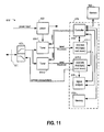
- FIG. 11 is a block diagram of a probe 610 according to some further embodiments, and which could be used in any of the implementations described above in connection with probes 10 or 110.
- Probe 610 is similar to probe 510, except that multiple tuners 614-1 and 614-2 are included to support parallel monitoring of even more frequency channels, and multiple DOCSIS PHY/MAC sub-processors 617-1 and 617-2 are included to provide additional demodulators and other circuitry to monitor additional channels in parallel.
- Remaining elements in FIG. 11 are similar to elements in FIG. 10 having a similar reference number offset by 100, except that controller 616 may execute additional program threads and memory 619 and/or memory 620 may store additional data and instructions corresponding to parallel monitoring of additional channels.
- additional tuners, DOCSIS PHY/MAC processors and/or other components may be included to further increase the number of channels that can be monitored in parallel.
- embodiments of the invention include one or more tangible machine-readable storage media storing instructions that, when executed by one or more processors or other devices, cause a probe to carry out operations such as are described herein.
- the embodiments discussed herein were chosen and described in order to explain the principles and the nature of various embodiments and their practical application to enable one skilled in the art to utilize the present invention in various embodiments and with various modifications as are suited to the particular use contemplated.
- the features of the embodiments described herein may be combined in all possible combinations of methods, apparatus, modules, systems, and machine readable media.
Landscapes
- Engineering & Computer Science (AREA)
- Multimedia (AREA)
- Signal Processing (AREA)
- Computer Networks & Wireless Communication (AREA)
- Computer Security & Cryptography (AREA)
- Health & Medical Sciences (AREA)
- Biomedical Technology (AREA)
- General Health & Medical Sciences (AREA)
- Two-Way Televisions, Distribution Of Moving Picture Or The Like (AREA)
- Small-Scale Networks (AREA)
Applications Claiming Priority (1)
| Application Number | Priority Date | Filing Date | Title |
|---|---|---|---|
| US12/469,168 US20100299713A1 (en) | 2009-05-20 | 2009-05-20 | Distributed Network Performance Monitoring |
Publications (2)
| Publication Number | Publication Date |
|---|---|
| EP2254332A2 true EP2254332A2 (de) | 2010-11-24 |
| EP2254332A3 EP2254332A3 (de) | 2014-11-05 |
Family
ID=42690239
Family Applications (1)
| Application Number | Title | Priority Date | Filing Date |
|---|---|---|---|
| EP10162738.8A Withdrawn EP2254332A3 (de) | 2009-05-20 | 2010-05-12 | Verteilte Netzwerkleistungsüberwachung |
Country Status (3)
| Country | Link |
|---|---|
| US (2) | US20100299713A1 (de) |
| EP (1) | EP2254332A3 (de) |
| CA (1) | CA2704091A1 (de) |
Families Citing this family (11)
| Publication number | Priority date | Publication date | Assignee | Title |
|---|---|---|---|---|
| US20100299713A1 (en) | 2009-05-20 | 2010-11-25 | Comcast Cable Communications, Llc | Distributed Network Performance Monitoring |
| US8660437B1 (en) | 2010-11-24 | 2014-02-25 | Emcore Corporation | Minimizing distortion due to wavelength dependent loss in WDM optical networks |
| US20120226842A1 (en) * | 2011-03-02 | 2012-09-06 | Research In Motion Limited, an Ontario, Canada corporation | Enhanced prioritising and unifying interrupt controller |
| US9021086B2 (en) * | 2011-10-21 | 2015-04-28 | Comcast Cable Communications, Llc | System and method for network management |
| US9386606B2 (en) * | 2014-09-03 | 2016-07-05 | Motorola Solutions, Inc. | Methods and systems for embedding supplementary data channel in LTE-based communication systems |
| US9571826B1 (en) | 2014-11-05 | 2017-02-14 | CSC Holdings, LLC | Integrated diagnostic and debugging of regional content distribution systems |
| US9800489B1 (en) * | 2014-12-17 | 2017-10-24 | Amazon Technologies, Inc. | Computing system monitor auditing |
| US10129102B2 (en) | 2016-05-11 | 2018-11-13 | Spirent Communications, Inc. | Service based testing |
| US10448007B2 (en) * | 2015-07-28 | 2019-10-15 | Spirent Communications, Inc. | Discovery and identification of layer 2 coax problems in MoCA networks |
| US11258679B2 (en) | 2015-07-28 | 2022-02-22 | Spirent Communications, Inc. | Systems and methods for automated testing of MoCA networks |
| WO2025259450A1 (en) * | 2024-05-31 | 2025-12-18 | Ppc Broadband, Inc. | Test probe for a cable tap comprising an inductance for minimising signal degradation |
Family Cites Families (40)
| Publication number | Priority date | Publication date | Assignee | Title |
|---|---|---|---|---|
| GB1554411A (en) * | 1975-08-09 | 1979-10-17 | Communications Patents Ltd | Control systems |
| US6650761B1 (en) * | 1999-05-19 | 2003-11-18 | Digimarc Corporation | Watermarked business cards and methods |
| US6411725B1 (en) * | 1995-07-27 | 2002-06-25 | Digimarc Corporation | Watermark enabled video objects |
| US5872588A (en) * | 1995-12-06 | 1999-02-16 | International Business Machines Corporation | Method and apparatus for monitoring audio-visual materials presented to a subscriber |
| US5862451A (en) * | 1996-01-22 | 1999-01-19 | Motorola, Inc. | Channel quality management in a cable telephony system |
| US6044090A (en) * | 1996-12-30 | 2000-03-28 | Motorola, Inc. | Method and apparatus for channel management in a communication system |
| JPH11308135A (ja) * | 1998-04-24 | 1999-11-05 | Sony Corp | 受信機 |
| ATE412289T1 (de) * | 1998-10-30 | 2008-11-15 | Broadcom Corp | Kabelmodemsystem |
| US6598232B1 (en) * | 1998-11-10 | 2003-07-22 | Nortel Networks Limited | Hybrid amplifier-regenerator for optimizing cable network transmissions |
| US7421723B2 (en) * | 1999-01-07 | 2008-09-02 | Nielsen Media Research, Inc. | Detection of media links in broadcast signals |
| US8724485B2 (en) * | 2000-08-30 | 2014-05-13 | Broadcom Corporation | Home network system and method |
| US20060015904A1 (en) * | 2000-09-08 | 2006-01-19 | Dwight Marcus | Method and apparatus for creation, distribution, assembly and verification of media |
| US7865915B1 (en) * | 2001-05-23 | 2011-01-04 | Cisco Technology, Inc. | Content discovery and differential advertising in video distribution networks |
| US20030028891A1 (en) * | 2001-08-03 | 2003-02-06 | General Instrument Corporation | System and method for diagnosing RF signal strength at a set-top terminal |
| CN1310457C (zh) * | 2001-09-04 | 2007-04-11 | 诺基亚公司 | 用于码速率适配的方法、装置与系统 |
| US20030110516A1 (en) * | 2001-10-31 | 2003-06-12 | Sony Corporation | System and method for embedding data in broadcast |
| US7162731B2 (en) * | 2002-02-07 | 2007-01-09 | Advent Networks, Inc. | Radio frequency characterization of cable plant and corresponding calibration of communication equipment communicating via the cable plant |
| US7577841B2 (en) * | 2002-08-15 | 2009-08-18 | Digimarc Corporation | Watermark placement in watermarking of time varying media signals |
| US7813957B1 (en) * | 2003-02-18 | 2010-10-12 | Microsoft Corporation | System and method for delivering payloads such as ads |
| CN1774923A (zh) * | 2003-04-17 | 2006-05-17 | 日本电信电话株式会社 | 电子水印嵌入运动图像传输系统、电子水印嵌入运动图像传输方法、信息处理装置、通信控制装置、电子水印嵌入运动图像处理程序以及存储了电子水印嵌入运动图像处理程序的存储介质 |
| US20050114879A1 (en) * | 2003-11-20 | 2005-05-26 | General Instrument Corporation | Monitoring signal quality on a cable network |
| US7895632B2 (en) * | 2004-02-12 | 2011-02-22 | Sony Corporation | Cable diagnostic and monitoring system |
| JP2006005527A (ja) * | 2004-06-16 | 2006-01-05 | Hitachi Ltd | 電子透かし埋め込みプログラム |
| US7623673B2 (en) * | 2005-03-30 | 2009-11-24 | Dolby Laboratories Licensing Corporation | Versatile watermark transport system |
| US20070058043A1 (en) * | 2005-08-30 | 2007-03-15 | Microsoft Corporation | Real-time IPTV channel health monitoring |
| US8566857B2 (en) * | 2005-09-20 | 2013-10-22 | Forefront Assets Limited Liability Company | Method, system and program product for broadcast advertising and other broadcast content performance verification utilizing digital artifacts |
| KR101233162B1 (ko) * | 2005-11-02 | 2013-02-15 | 엘지전자 주식회사 | 케이블 방송 수신 장치, 진단 정보 데이터 구조 및 진단정보 전송 방법 |
| US20070169162A1 (en) * | 2006-01-18 | 2007-07-19 | Srinivas Kola | Hierarchical communications network with upstream signal controllable from head end |
| US20090131123A1 (en) * | 2006-03-17 | 2009-05-21 | Nokia Corporation | Reduced power consumption in software radios |
| WO2007128097A1 (en) * | 2006-05-05 | 2007-11-15 | Mariner Partners, Inc. | Transient video anomaly analysis and reporting system |
| US20080080607A1 (en) * | 2006-09-29 | 2008-04-03 | Punit Shah | Dynamic equalizer algorithm in digital communication equipment for multipath compensation and interference cancellation |
| US8189651B2 (en) * | 2006-10-12 | 2012-05-29 | Pingnan Shi | Measuring Hum in a digital TV signal |
| US20080151873A1 (en) * | 2006-12-21 | 2008-06-26 | Mike Borsetti | Virtual internet protocol interconnection service |
| US8181206B2 (en) * | 2007-02-28 | 2012-05-15 | Time Warner Cable Inc. | Personal content server apparatus and methods |
| US8194657B2 (en) * | 2007-05-22 | 2012-06-05 | Actiontec Electronics, Inc. | Systems and methods for dynamic quality of service |
| JP5135943B2 (ja) * | 2007-08-09 | 2013-02-06 | 株式会社日立製作所 | 放送受信装置 |
| KR100917321B1 (ko) * | 2007-12-05 | 2009-09-14 | 한국전자통신연구원 | 케이블 모뎀을 위한 하향 서비스 플로우 분류 장치 및방법 |
| US20090164550A1 (en) * | 2007-12-20 | 2009-06-25 | Nortel Networks Limited | Media monitoring |
| US20090328119A1 (en) * | 2008-06-25 | 2009-12-31 | Alcatel Lucent | Packet Recovery Server Based Triggering Mechanism for IPTV Diagnostics |
| US20100299713A1 (en) | 2009-05-20 | 2010-11-25 | Comcast Cable Communications, Llc | Distributed Network Performance Monitoring |
-
2009
- 2009-05-20 US US12/469,168 patent/US20100299713A1/en not_active Abandoned
-
2010
- 2010-05-12 EP EP10162738.8A patent/EP2254332A3/de not_active Withdrawn
- 2010-05-13 CA CA2704091A patent/CA2704091A1/en not_active Abandoned
-
2013
- 2013-07-01 US US13/932,629 patent/US9930327B2/en active Active
Non-Patent Citations (1)
| Title |
|---|
| None |
Also Published As
| Publication number | Publication date |
|---|---|
| US20100299713A1 (en) | 2010-11-25 |
| US20130305302A1 (en) | 2013-11-14 |
| EP2254332A3 (de) | 2014-11-05 |
| US9930327B2 (en) | 2018-03-27 |
| CA2704091A1 (en) | 2010-11-20 |
Similar Documents
| Publication | Publication Date | Title |
|---|---|---|
| US9930327B2 (en) | Distributed network performance monitoring | |
| US20120213259A1 (en) | Cable modem for network measurements | |
| US9203653B2 (en) | Method and apparatus for spectrum monitoring | |
| US6757253B1 (en) | Spectrum management method for a cable data system | |
| US20070107034A1 (en) | Combination meter for evaluating video delivered via Internet protocol | |
| US7162731B2 (en) | Radio frequency characterization of cable plant and corresponding calibration of communication equipment communicating via the cable plant | |
| US8159960B2 (en) | Content processing device monitoring | |
| EP1238542B1 (de) | Überwachung der dienstgüte einer digitalen fernsehverbindung | |
| US10764532B2 (en) | Method and system for locating ingress utilizing customer premises equipment | |
| US20050114879A1 (en) | Monitoring signal quality on a cable network | |
| CA2707170A1 (en) | Testing a content-delivery system | |
| US20180367790A1 (en) | Predictive network testing | |
| US7961719B2 (en) | End of line monitor using DOCSIS | |
| US10715213B1 (en) | Leakage detection for OFDM system with fixed pilot | |
| US20090128708A1 (en) | Monitoring unit for use in a system for multimedia content distribution | |
| KR100636323B1 (ko) | 디지털 방송 수신기에서의 모드 변경 장치 및 방법 | |
| KR100844316B1 (ko) | Hfc 전송망 감시장치 | |
| JP2004350241A (ja) | 受信装置、送出装置、デジタルcatvシステム、共同受信装置および共同受信システム | |
| AU756820B2 (en) | Surveillance of the quality of service in a digital television link | |
| Wu et al. | QoS Monitoring and Troubleshooting of a Large Scale IPTV Deployment |
Legal Events
| Date | Code | Title | Description |
|---|---|---|---|
| PUAI | Public reference made under article 153(3) epc to a published international application that has entered the european phase |
Free format text: ORIGINAL CODE: 0009012 |
|
| AK | Designated contracting states |
Kind code of ref document: A2 Designated state(s): AL AT BE BG CH CY CZ DE DK EE ES FI FR GB GR HR HU IE IS IT LI LT LU LV MC MK MT NL NO PL PT RO SE SI SK SM TR |
|
| AX | Request for extension of the european patent |
Extension state: BA ME RS |
|
| PUAL | Search report despatched |
Free format text: ORIGINAL CODE: 0009013 |
|
| AK | Designated contracting states |
Kind code of ref document: A3 Designated state(s): AL AT BE BG CH CY CZ DE DK EE ES FI FR GB GR HR HU IE IS IT LI LT LU LV MC MK MT NL NO PL PT RO SE SI SK SM TR |
|
| AX | Request for extension of the european patent |
Extension state: BA ME RS |
|
| RIC1 | Information provided on ipc code assigned before grant |
Ipc: H04N 21/647 20110101ALI20141001BHEP Ipc: H04N 7/10 20060101AFI20141001BHEP Ipc: H04N 21/61 20110101ALI20141001BHEP |
|
| 17P | Request for examination filed |
Effective date: 20150428 |
|
| RBV | Designated contracting states (corrected) |
Designated state(s): AL AT BE BG CH CY CZ DE DK EE ES FI FR GB GR HR HU IE IS IT LI LT LU LV MC MK MT NL NO PL PT RO SE SI SK SM TR |
|
| STAA | Information on the status of an ep patent application or granted ep patent |
Free format text: STATUS: EXAMINATION IS IN PROGRESS |
|
| 17Q | First examination report despatched |
Effective date: 20171010 |
|
| STAA | Information on the status of an ep patent application or granted ep patent |
Free format text: STATUS: THE APPLICATION IS DEEMED TO BE WITHDRAWN |
|
| 18D | Application deemed to be withdrawn |
Effective date: 20191203 |