EP2253882A1 - Heating apparatus - Google Patents
Heating apparatus Download PDFInfo
- Publication number
- EP2253882A1 EP2253882A1 EP09716623A EP09716623A EP2253882A1 EP 2253882 A1 EP2253882 A1 EP 2253882A1 EP 09716623 A EP09716623 A EP 09716623A EP 09716623 A EP09716623 A EP 09716623A EP 2253882 A1 EP2253882 A1 EP 2253882A1
- Authority
- EP
- European Patent Office
- Prior art keywords
- flow passage
- pipe
- gas
- combustion
- uncombusted
- Prior art date
- Legal status (The legal status is an assumption and is not a legal conclusion. Google has not performed a legal analysis and makes no representation as to the accuracy of the status listed.)
- Granted
Links
Images




Classifications
-
- F—MECHANICAL ENGINEERING; LIGHTING; HEATING; WEAPONS; BLASTING
- F22—STEAM GENERATION
- F22B—METHODS OF STEAM GENERATION; STEAM BOILERS
- F22B7/00—Steam boilers of furnace-tube type, i.e. the combustion of fuel being performed inside one or more furnace tubes built-in in the boiler body
- F22B7/02—Steam boilers of furnace-tube type, i.e. the combustion of fuel being performed inside one or more furnace tubes built-in in the boiler body without auxiliary water tubes
-
- F—MECHANICAL ENGINEERING; LIGHTING; HEATING; WEAPONS; BLASTING
- F22—STEAM GENERATION
- F22B—METHODS OF STEAM GENERATION; STEAM BOILERS
- F22B37/00—Component parts or details of steam boilers
- F22B37/02—Component parts or details of steam boilers applicable to more than one kind or type of steam boiler
- F22B37/10—Water tubes; Accessories therefor
- F22B37/101—Tubes having fins or ribs
-
- F—MECHANICAL ENGINEERING; LIGHTING; HEATING; WEAPONS; BLASTING
- F22—STEAM GENERATION
- F22B—METHODS OF STEAM GENERATION; STEAM BOILERS
- F22B37/00—Component parts or details of steam boilers
- F22B37/02—Component parts or details of steam boilers applicable to more than one kind or type of steam boiler
- F22B37/10—Water tubes; Accessories therefor
- F22B37/12—Forms of water tubes, e.g. of varying cross-section
Definitions
- the present invention relates a heating apparatus for heating a fluid to be heated.
- This application claims the benefit of Japanese Patent Application 2008-053901 filed in Japan on March 4, 2008 and Japanese Patent Application 2008-053903 filed in Japan on March 4, 2008, the entire disclosure of which is incorporated by reference herein.
- a small heating apparatus may be installed for the heating of water for use in bathing or for steaming during cooking.
- a heating apparatus has been disclosed which heats water flowing in a pipe using high-temperature combustion gas produced by combustion of a fuel in the presence of combustion air to thereby evaporate the water into steam.
- the heating apparatus may be also used for heating of various liquids (a liquid to be heated) (Patent Literature 1).
- Patent Literature 1 Japanese Patent Application, First Publication No. 2007-139358
- a large combustion chamber must be provided in order to maintain the time for complete combustion within the combustion chamber.
- combustion gas has a considerably high temperature, there is the possibility that the uncombusted gas may undergo spontaneous combustion as a result of excessive heating prior to supply of the uncombusted gas to the combustion chamber and that flame propagation may occur thereby resulting in occurrence of combustion outside of the combustion chamber.
- a large amount of heat is radiated to the periphery from a large combustion chamber, and thereby results in a reduction in energy efficiency.
- the present invention is proposed in light of the above problems, and has the object of providing a heating apparatus for heating of a liquid to be heated that reduces the size of a combustion chamber, stabilizes the flame in the combustion chamber and thereby improves energy efficiency.
- the present invention is a heating apparatus for heating of a liquid to be heated including a first flow passage in which uncombusted gas that contains a combustible fuel is injected from a nozzle hole that is smaller than the flame quenching distance at a flow speed to thereby enable flame maintenance and is combusted, and thereby enables flow of combustion gas resulting from the combustion, and a second flow passage enabling flow of uncombusted gas supplied through the nozzle hole.
- the above configuration may form the second flow passage about the first flow passage.
- uncombusted gas is heated by flowing through the second flow passage formed about the first flow passage which enables flow of the combustion gas.
- the entire periphery of the second flow passage does not make contact with the first flow passage. Therefore a part of the heat amount transmitted from the combustion gas is radiated from the uncombusted gas.
- a third flow passage is surrounded by the first flow passage and enables flow of a liquid to be heated.
- a configuration in which the third flow passage is formed from an inner space of a third pipe, a configuration in which the first flow passage is formed from a space sandwiched by the third pipe and the first pipe concentrically enclosing the third pipe, and a configuration in which the second flow passage is formed from a space sandwiched by the first pipe and the second pipe concentrically enclosing the first pipe are enabled.
- a plurality of fins may be provided to project towards the first flow passage from an outer peripheral face of the third pipe.
- the third pipe is curved toward the first flow passage side and the second flow passage side at a predetermined interval.
- a configuration is possible in which the first flow passage is formed about the second flow passage, and the third flow passage enables flow of the liquid to be heated and is formed about the first flow passage.
- the first flow passage is formed about the second flow passage that enables flow of uncombusted gas, and combustion gas flows in the first flow passage.
- the uncombusted gas flowing in the second flow passage is heated by high-temperature combustion gas which flows in the first flow passage.
- a stable flame is formed by injection of uncombusted gas from the second flow passage at a flow speed enabling maintenance of a flame through a nozzle hole that is set to be smaller than the flame quenching distance.
- the third flow passage is formed about the first flow passage which enables combustion of uncombusted gas by the stable flame and flow of the uncombusted gas, and the liquid to be heated flows in the third flow passage.
- a guide portion may be provided to guide the combustion gas from the first flow passage to a region opposite the first flow passage that is a region on an outer side of the third flow passage.
- the second flow passage is configured from an inner space in the second pipe
- the first flow passage is configured from the space sandwiched by the second pipe and the first pipe that concentrically surrounds the second pipe
- the third flow passage is configured from the space sandwiched by the first pipe and the third pipe that concentrically surrounds the first pipe.
- the second flow passage is configured from an inner space in the second pipe
- the third flow passage is configured from the inner space of a plurality of fourth pipes disposed at a distance from the second pipe centering on the second pipe
- the first flow passage is configured from a space surrounded by the second pipe and the partitions closing the interval between the pairs of fourth pipes and fourth pipes.
- a first embodiment of a heating apparatus according to the present invention will be described below making reference to the figures and using an example of a small boiler.
- the dimensions of respective members have been suitably varied to a size that enables recognition of each member.
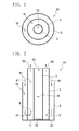
- FIG. 1 to FIG. 3 are schematic views of a small boiler B1 according to the present embodiment.
- FIG. 1 is a perspective view
- FIG. 2 is a horizontal sectional view
- FIG. 3 is a vertical sectional view.
- a small boiler B1 according to the present embodiment has a three-layered structure in which a first pipe 1 (first pipe), a second pipe 2 (second pipe), a third pipe 3 (third pipe) are disposed concentrically when viewed horizontally.
- the first pipe 1 extends in a vertical direction and the lower end 11 thereof is closed.
- a plurality of nozzle holes 12 set so that the diameter thereof is smaller than the flame quenching distance of the uncombusted gas is provided in a side partition portion near to the lower end 11.
- the first pipe 1 is formed from a material that has superior heat transmission characteristics (for example, brass or the like).
- the second pipe 2 extends vertically and concentrically surrounds the first pipe 1. A lower end 21 thereof is closed, and in the same manner as the first pipe 1, it is formed from a material having superior heat transmission characteristics.
- the third pipe 3 extends vertically and is inserted into the first pipe 1. A lower end 31 thereof is closed, and in the same manner as the first pipe 1 and the second pipe 2, the third pipe 3 is preferably formed from a material having superior heat transmission characteristics.
- An inner space in the third pipe 3 forms a water flow passage R3 (third flow passage) which enables flow of the water (liquid to be heated) W.
- the water flow passage R3 is configured from the inner space of the third pipe 3.
- a water supply portion (not shown) to supply water W to the water flow passage R3 is connected in proximity to the lower end of the water flow passage R3.
- a regulated flow amount of water W is supplied to the water flow passage R3 by the water supply portion.
- a discharge portion (not shown) is connected to enable discharge of steam produced by evaporation of water W in the water flow passage R3 in proximity to the upper end of the water flow passage R3.
- a regulated amount of steam is discharged to an external portion from the water flow passage R3 via the discharge portion.
- a space sandwiched by the third pipe 3 and the first pipe 1 forms a combustion gas flow passage R1 (first flow passage) in which s combustion of uncombusted gas G1 occurs and combustion gas G2 produced by combustion of the uncombusted gas G1 can flow.
- the combustion gas flow passage R1 is configured from a space sandwiched by the third pipe 3 and the first pipe 1 that concentrically surrounds the third pipe.
- the water flow passage R3 is surrounded by the combustion gas flow passage R1.
- a section near to the lower end of the combustion gas flow passage R1 (near to the nozzle hole 12) forms a combustion chamber K in which uncombusted gas G1 injected from the nozzle holes 12 is combusted.
- An ignition apparatus (not shown) is provided in the combustion chamber K.
- a space sandwiched by the first pipe 1 and the second pipe 2 forms the uncombusted gas flow passage R2 (second flow passage) that enables flow of uncombusted gas G1 including combustible fuel.
- the uncombusted gas flow passage R2 is configured from a space sandwiched by the first pipe 1 and the second pipe 2 that concentrically covers the first pipe 1.
- the upper end portion of the second pipe 2 is connected to an uncombusted gas supply apparatus (not shown) that supplies uncombusted gas G1 to the uncombusted gas flow passage R2.
- the uncombusted gas G1 may be a mixed gas of fuel with an oxidation agent.
- the fuel may be an oil fuel, natural gas or the like.
- firstly uncombusted gas G1 is supplied from the uncombusted gas supply apparatus that is connected to the second pipe 2 to the uncombusted gas flow passage R2.
- the uncombusted gas G1 injected from nozzle holes 12 formed in the first pipe 1 is ignited and combusted to thereby form a flame in the combustion chamber K.
- the combustion gas G2 produced by the combustion of the uncombusted gas G1 flows through the combustion gas flow passage R2 and is discharged.
- the uncombusted gas G1 heated by heat exchange with the combustion gas G2 is injected in a heated state into an inner portion of the first pipe 1 through the nozzle holes 12.
- the uncombusted gas G1 is injected from the nozzle holes 12 and combusted in the combustion chamber K.
- the nozzle holes 12 formed in the first pipe 1 are set to be smaller than the flame quenching distance of the uncombusted gas G1 in the combustion environment of the combustion chamber K, it is possible to suppress propagation of the flame to the uncombusted gas flow passage R2. Furthermore since the uncombusted gas flow passage R2 is formed about the combustion gas flow passage R1, the entire periphery of the uncombusted gas flow passage R2 does not come into contact with the combustion gas flow passage R1, and a part of the heat amount transmitted from the combustion gas G2 is radiated from the uncombusted gas G1.
- uncombusted gas G1 supplied to the combustion chamber K through the uncombusted gas flow passage R2 is heated by the combustion gas G2 flowing through the combustion gas flow passage R1 in a state in which combustion in the combustion chamber K is continuously executed. Therefore, a stable flame can be formed by a combustion chamber K which is extremely small in comparison to the combustion chamber in a conventional heating apparatus.
- Water W in the water flow passage R3 is heated and evaporated by the combustion gas G2 in the combustion gas flow passage R2 and the flame in the combustion chamber K in a state in which a stable flame is formed in the combustion chamber K and combustion is continuously executed. More specifically, heat produced by combustion is transmitted to water W through the second pipe 2 that functions as a heat exchange partition, and therefore the water W is heated and evaporates. The steam produced by evaporation of the water W is discharged to an external portion of the small boiler B1 through the discharge portion (not shown). Since the water flow passage R3 is surrounded by the combustion gas flow passage R1, a heat amount can be transmitted to the water W from the entire periphery of the water flow passage R3 and thereby enables efficient heating of the water W.
- an uncombusted gas flow passage R2 which enables flow of the uncombusted gas G1 is formed about the combustion gas flow passage R1 which enables flow of the combustion gas G2. Consequently, the entire periphery of the uncombusted gas flow passage R2 makes no contact with the combustion gas flow passage R1, and a portion of the heat amount transmitted from the combustion gas G2 is radiated from the uncombusted gas G1.
- the combustion chamber K can be made smaller due to the heating of the uncombusted gas G1, and it is possible to suppress the overheating of the uncombusted gas G1 and stabilize the flame in the combustion chamber K. Therefore the combustion chamber K can be made smaller and the flame in the combustion chamber K can be stabilized.
- FIG. 4 is a vertical sectional view of the schematic configuration of a small boiler B2 according to an embodiment.
- the small boiler B2 according to the present embodiment includes a fourth pipe 4 which concentrically surrounds the second pipe 2.
- a space sandwiched by the second pipe 2 and the fourth pipe 4 is formed as a storage portion 5 that stores water W and is connected to the water flow passage R3.
- the small boiler B2 in the present embodiment having the above configuration, although water W stored temporarily in the water storage portion 5 is supplied to the water flow passage R3, the water W receives a portion of the heat amount radiated from the uncombusted gas G1 in the storage portion 5. Consequently, the amount of heat radiated from the uncombusted gas G1 can be used to heat the water W, and therefore enables more efficient heating of the water W.
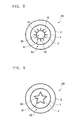
- FIG. 5 is a horizontal sectional view of the schematic configuration of a small boiler B3 according to an embodiment.
- the small boiler B3 according to the present embodiment includes a plurality of fins 10 that project towards the combustion gas flow passage R1 from an outer peripheral face of the third pipe 3.
- the fins 10 are integrally formed with the third pipe 3 and are formed from a material having superior heat transmission characteristics in the same manner as the third pipe 3.
- the fins 10 enable an increase in the heat exchanging surface area with water W flowing through the water flow passage R3 and the combustion gas G2 flowing through the combustion gas flow passage R1, and thereby enable more efficient heating of the water.
- FIG. 7 is a horizontal sectional view of the schematic configuration of a small boiler B4 according to an embodiment.
- the small boiler B4 according to the present embodiment is such that the second pipe 2 is configured in a star shape that is curved toward the combustion gas flow passage R1 and the water flow passage R3 at a fixed interval.
- the formation of the third pipe 3 into a star shape which is curved at a fixed interval enables an increase in the heat exchanging surface area with water W flowing through the water flow passage R3 and the combustion gas G2 flowing through the combustion gas flow passage R1, and thereby enables more efficient heating of the water.
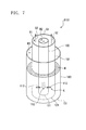
- FIG. 7 to FIG. 9 are schematic views of a small boiler B101 according to a fifth embodiment of the present invention.
- FIG. 7 is a perspective view
- FIG. 8 is a horizontal sectional view
- FIG. 9 is a vertical sectional view.
- a small boiler B101 according to the present embodiment has a three-layered structure in which a first pipe 101 (first pipe), a second pipe 102 (second pipe), a third pipe 103 (third pipe) are disposed concentrically when viewed horizontally.
- the second pipe 102 extends vertically and a lower end 111 thereof is closed. A plurality of nozzle holes 112 set so that the diameter thereof is smaller than the flame quenching distance of the uncombusted gas is provided in a side partition portion near to the lower end 111.
- the second pipe 102 is formed from a material that has superior heat transmission characteristics (for example, brass or the like).
- the inner space in the second pipe 102 forms an uncombusted gas flow passage R2 (second flow passage) which enables flow of the uncombusted gas G1 including combustible fuel. More specifically, in the small boiler B101 according to the present embodiment, the uncombusted gas flow passage R2 is configured from the inner space of the second pipe 102.
- An upper end portion of the second pipe 102 is connected to the uncombusted gas supply passage (not shown) that supplies uncombusted gas G1 to the uncombusted gas flow passage R2.
- the uncombusted gas G1 may be a mixture gas of fuel with an oxidation agent.
- the fuel may be an oil fuel, natural gas or the like.
- the first pipe 101 extends vertically and is disposed to concentrically surround the second pipe 102.
- a lower end 121 thereof is closed, and in the same manner as the second pipe 102, it is formed from a material displaying superior heat transmission characteristics.
- a space sandwiched by the first pipe 101 and the second pipe 102 forms a combustion gas flow passage R1 (first flow passage) which enables combustion of uncombusted gas G1 and enables flow of the combustion gas G2 produced by the combustion of uncombusted gas G1.
- the combustion gas flow passage R1 is configured from a space sandwiched by the second pipe 2 and the first pipe 101 that concentrically surrounds the second pipe 2.
- a section near to the lower end of the combustion gas flow passage R1 (near to the nozzle hole 112) forms a combustion chamber K in which uncombusted gas G1 injected from the nozzle holes 112 is combusted.
- An ignition apparatus (not shown) is provided in the combustion chamber K.
- the third pipe 103 extends vertically and is disposed to concentrically surround the first pipe 101. A lower end 131 thereof is closed, and it is preferred that the third pipe 3 is formed from a material displaying low heat transmission characteristics.
- a space sandwiched by the first pipe 101 and the third pipe 103 forms a water flow passage R3 (third flow passage) which enables flow of the water (liquid to be heated) W. More specifically, in the small boiler B101 according to the present embodiment, the water flow passage R3 is configured from a space sandwiched by the first pipe 101 and the third pipe 103 that concentrically surrounds the first pipe 101.
- a water supply portion for supplying water to the water flow passage R3 is connected to a section near to the lower end of the water flow passage R3, and a regulated flow amount of water W is supplied to the water flow passage R3 by the water supply portion.
- a discharge portion for discharging steam produced by evaporation of water W in the water flow passage R3 is connected in proximity to an upper end of the water flow passage R3, and a regulated flow amount of steam is discharged from the water flow passage R3 to an external portion by the discharge portion.
- firstly uncombusted gas G1 is supplied from the uncombusted gas supply apparatus that is connected to the second pipe 102 to the uncombusted gas flow passage R2.
- the uncombusted gas G1 injected from nozzle holes 112 formed in the second pipe 102 is ignited and combusted to thereby form a flame in the combustion chamber K.
- the combustion gas G2 produced by the combustion of the uncombusted gas G1 flows through the combustion gas flow passage R1 and is discharged.
- the uncombusted gas G1 heated by heat exchange with the combustion gas G2 is ejected into an outer portion of the second pipe 102 through the nozzle holes 112 in a state of being heated to almost an ignition temperature.
- the uncombusted gas G1 ejected from the nozzle holes 112 is ignited by the flame formed in the combustion chamber K, and is combusted.
- the nozzle holes 112 formed in the second pipe 102 are set to be smaller than the flame quenching distance of the uncombusted gas G1 in the combustion environment of the combustion chamber K, the flame does not propagate to the uncombusted gas flow passage R2. Consequently the flame is stabilized in the combustion chamber K, and thereby enables continuous combustion.
- uncombusted gas G1 supplied to the combustion chamber K through the uncombusted gas flow passage R2 is heated by the combustion gas G2 flowing through the combustion gas flow passage R1 in a state in which combustion in the combustion chamber K is continuously executed. Therefore, a stable flame can be formed by a combustion chamber K which is extremely small in comparison to the combustion chamber in a conventional heating apparatus.
- Water W in the water flow passage R3 is heated and evaporated by the combustion gas G2 in the combustion gas flow passage R1 and the flame in the combustion chamber K in a state in which a stable flame is formed in the combustion chamber K and combustion is continuously executed. More specifically, a heat amount of the flame and a heat amount of the combustion gas G2 are transmitted to the water W through the first pipe 101 that functions as a heat exchange partition, and therefore the water W is heated and evaporated.
- the steam produced by evaporation of the water W is discharged to an external portion of the small boiler B101 through the discharge portion (not shown).
- a combustion gas flow passage R1 in which combustion gas G2 flows is formed about the uncombusted gas flow passage R2 which enables flow of the uncombusted gas G1. Consequently, the uncombusted gas G1 flowing in the uncombusted gas flow passage R2 is heated by the combustion gas G2 that flows in the combustion gas flow passage R1. Furthermore a stable flame is formed by injection of uncombusted gas G1 from the uncombusted gas flow passage R2 at a flow speed enabling maintenance of a flame through a nozzle holes 112 that are set to be smaller than the flame quenching distance. This stable flame is enabled even when coming into direct contact with the partition face (first pipe 101) making contact with the cold liquid.
- the water flow passage R3 is formed about the combustion gas flow passage R1 which forms the stable flame and water W is supplied to the water flow passage R3.
- the water W that flows in the third flow passage is heated by direct heating of the water flow passage R3 by the stable flame. Therefore in comparison to heating the water flow passage R3 only by combustion gas G2, the amount of heat can be efficiently transmitted to the water W. Consequently, the small boiler B101 of the present embodiment enables an improvement in energy efficiency.
- the uncombusted gas G1 flowing in the combusted gas flow passage R2 is heated by high-temperature combustion gas G2 flowing in the combustion gas flow passage R1
- the heated uncombusted gas G1 is combusted by ejection from the uncombusted gas flow passage R2 at a flow speed enabling maintenance of a flame through a nozzle hole 112 that is set to be smaller than the flame quenching distance.
- the adoption of the above configuration enables sufficient heating of the uncombusted gas G1 by the high-temperature combustion gas G2, and therefore enables continuous stable combustion in a small combustion chamber K.
- the combustion chamber can be made smaller thereby enabling downsizing of the apparatus.
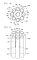
- FIG. 10 and FIG. 11 are schematic views of a small boiler B102 according to a fifth embodiment of the present invention.
- FIG. 10 is a horizontal sectional view and FIG. 11 is a perspective view.
- the uncombusted gas flow passage R2 of the small boiler B102 according to the present embodiment is configured from an inner space in the second pipe 102 in the same manner as the small boiler B101 in the fifth embodiment.
- the water flow passage R3 is configured from the inner space of a plurality of fourth pipes 104 disposed at a distance from the second pipe 102 centering on the second pipe 102
- the combustion gas flow passage R1 is configured from a space surrounded by partitions 105 closing the second pipe 102 and the space between the pairs of fourth pipes 104 and fourth pipes 104.
- the height of the partition 105 is set to be low in comparison with the height of the second pipe 102 and the fourth pipe 104.
- the space functions as a guide portion 106 for guiding the combustion gas G2 into a region on an outer side of the water flow passage R3and opposite the combustion gas flow passage R1.
- FIG. 12 is a horizontal sectional view of the schematic configuration of a small boiler according to a seventh embodiment of the present invention.
- the small boiler B103 according to the present embodiment includes a plurality of fins 110 that project towards the water flow passage R3 from an outer peripheral face of the first pipe 101.
- the fins 110 are integrally formed with the first pipe 101 and are formed from a material having superior heat transmission characteristics in the same manner as the first pipe 101.
- the fins 110 enable an increase in the heat exchanging surface area with water W flowing through the water flow passage R3 and the combustion gas G2 flowing through the combustion gas flow passage R1, and thereby enable more efficient heating of the water. Therefore energy efficiency can be further improved.
- FIG. 13 is a horizontal sectional view of the schematic configuration of a small boiler B104 according to the present embodiment.
- the small boiler B104 according to the present embodiment is such that the first pipe 1 is configured in a star shape that is curved toward the combustion gas flow passage R1 and the water flow passage R3 at a fixed interval.
- the formation of the first pipe 101 into a star shape which is curved at a fixed interval enables an increase in the heat exchanging surface area with water W flowing through the water flow passage R3 and the combustion gas G2 flowing through the combustion gas flow passage R1, and thereby enables more efficient heating of the water.
- a small boiler was described as an example of a heating apparatus.
- the present invention is not limited in this regard, and may be applied to a boiling apparatus for heating water for the purpose of making hot water, or to an apparatus heating oil or gas.
- the present invention may be applied to a large boiler, or to industrial product such as a fluidized-bed boiler using a heated powder material.
- the heating apparatus according to the present invention is applied to a recycling fluidized-bed boiler, the particle material may be transported using combustion gas.
- the external shape and sectional shape of the first pipe 1 and 101, the second pipe 2 and 102, the third pipe 3 and 103, and the fourth pipe 4 and 104 are merely exemplary, and may be configured in an arbitrary manner.
- a heating apparatus for heating a liquid to be heated enables stabilization of a flame in a combustion chamber and downsizing of the combustion chamber, in addition to improving energy efficiency.
Landscapes
- Engineering & Computer Science (AREA)
- Physics & Mathematics (AREA)
- Thermal Sciences (AREA)
- Mechanical Engineering (AREA)
- General Engineering & Computer Science (AREA)
- Chemical & Material Sciences (AREA)
- Combustion & Propulsion (AREA)
- Instantaneous Water Boilers, Portable Hot-Water Supply Apparatuses, And Control Of Portable Hot-Water Supply Apparatuses (AREA)
- Gas Burners (AREA)
- Combustion Of Fluid Fuel (AREA)
Abstract
Description
- The present invention relates a heating apparatus for heating a fluid to be heated. This application claims the benefit of Japanese Patent Application
2008-053901 2008-053903 - In an eating and drinking establishments, or in lodging facilities, a small heating apparatus may be installed for the heating of water for use in bathing or for steaming during cooking. For example, a heating apparatus has been disclosed which heats water flowing in a pipe using high-temperature combustion gas produced by combustion of a fuel in the presence of combustion air to thereby evaporate the water into steam. Furthermore in addition to production of steam or hot water, the heating apparatus may be also used for heating of various liquids (a liquid to be heated) (Patent Literature 1).
[Patent Literature 1] Japanese Patent Application, First Publication No.2007-139358 - Meanwhile, in a conventional heating apparatus, a large combustion chamber must be provided in order to maintain the time for complete combustion within the combustion chamber. As a result, it is not possible to sufficiently downsize the heating apparatus. Consequently, a stable flame can be maintained even in a small combustion chamber by performing combustion after heating uncombusted gas in advance using combustion gas. However since combustion gas has a considerably high temperature, there is the possibility that the uncombusted gas may undergo spontaneous combustion as a result of excessive heating prior to supply of the uncombusted gas to the combustion chamber and that flame propagation may occur thereby resulting in occurrence of combustion outside of the combustion chamber. Furthermore a large amount of heat is radiated to the periphery from a large combustion chamber, and thereby results in a reduction in energy efficiency.
- The present invention is proposed in light of the above problems, and has the object of providing a heating apparatus for heating of a liquid to be heated that reduces the size of a combustion chamber, stabilizes the flame in the combustion chamber and thereby improves energy efficiency.
- In order to achieve the above object, the present invention is a heating apparatus for heating of a liquid to be heated including a first flow passage in which uncombusted gas that contains a combustible fuel is injected from a nozzle hole that is smaller than the flame quenching distance at a flow speed to thereby enable flame maintenance and is combusted, and thereby enables flow of combustion gas resulting from the combustion, and a second flow passage enabling flow of uncombusted gas supplied through the nozzle hole.
- The above configuration may form the second flow passage about the first flow passage.
- According to the heating apparatus, uncombusted gas is heated by flowing through the second flow passage formed about the first flow passage which enables flow of the combustion gas. In order to form the second flow passage about the first flow passage, the entire periphery of the second flow passage does not make contact with the first flow passage. Therefore a part of the heat amount transmitted from the combustion gas is radiated from the uncombusted gas.
- In the present invention, a third flow passage is surrounded by the first flow passage and enables flow of a liquid to be heated.
- According to the heating apparatus above, a configuration in which the third flow passage is formed from an inner space of a third pipe, a configuration in which the first flow passage is formed from a space sandwiched by the third pipe and the first pipe concentrically enclosing the third pipe, and a configuration in which the second flow passage is formed from a space sandwiched by the first pipe and the second pipe concentrically enclosing the first pipe are enabled.
- In the above configuration, a plurality of fins may be provided to project towards the first flow passage from an outer peripheral face of the third pipe.
- In the above configuration, the third pipe is curved toward the first flow passage side and the second flow passage side at a predetermined interval.
- A configuration is possible in which the first flow passage is formed about the second flow passage, and the third flow passage enables flow of the liquid to be heated and is formed about the first flow passage.
- According to the heating apparatus above, the first flow passage is formed about the second flow passage that enables flow of uncombusted gas, and combustion gas flows in the first flow passage. Thus the uncombusted gas flowing in the second flow passage is heated by high-temperature combustion gas which flows in the first flow passage. Furthermore a stable flame is formed by injection of uncombusted gas from the second flow passage at a flow speed enabling maintenance of a flame through a nozzle hole that is set to be smaller than the flame quenching distance. Furthermore, the third flow passage is formed about the first flow passage which enables combustion of uncombusted gas by the stable flame and flow of the uncombusted gas, and the liquid to be heated flows in the third flow passage.
- In the above configuration, a guide portion may be provided to guide the combustion gas from the first flow passage to a region opposite the first flow passage that is a region on an outer side of the third flow passage.
- In the above configuration, the second flow passage is configured from an inner space in the second pipe, the first flow passage is configured from the space sandwiched by the second pipe and the first pipe that concentrically surrounds the second pipe, and the third flow passage is configured from the space sandwiched by the first pipe and the third pipe that concentrically surrounds the first pipe.
- In the above configuration, the second flow passage is configured from an inner space in the second pipe, the third flow passage is configured from the inner space of a plurality of fourth pipes disposed at a distance from the second pipe centering on the second pipe, and the first flow passage is configured from a space surrounded by the second pipe and the partitions closing the interval between the pairs of fourth pipes and fourth pipes.
- According to the heat apparatus in the present invention, the following excellent effects are obtained.
- (1) The second passage which enables flow of the uncombusted gas is formed about the first flow passage which enables flow of the combustion gas. Therefore although the entire periphery of the second flow passage does not come into contact with the first flow passage, a part of the heat amount transmitted from the combustion gas is radiated from the uncombusted gas. As a result, in addition to reduce the size of a combustion chamber by heating uncombusted gas, overheating of the uncombusted gas can be suppressed, and it is possible to form a stable flame in the combustion chamber. Therefore the combustion chamber in the heating apparatus that heats the liquid to be heated can be reduced in size and maintenance of a stable flame in the combustion chamber is possible.
- (2) The first passage is formed about the second flow passage which enables flow of the uncombusted gas and the combustion gas flows in the first passage. Therefore the uncombusted gas flowing in the second passage can be heated by the high-temperature combustion gas flowing in the first flow passage. Furthermore a stable flame is formed by injection of uncombusted gas from the second flow passage at a flow speed enabling maintenance of a flame through a nozzle hole that is set to be smaller than the flame quenching distance. This stable flame enables stable combustion even when coming into direct contact with the partition face making contact with the cold liquid to be heated, and enables efficient transmission of heat to the partition face. Furthermore the third flow passage is formed about the first flow passage in which the uncombusted gas is combusted by the stable flame and enables flow of the combustion gas, and the liquid to be heated flows in the third flow passage. As a result, the liquid to be heated flowing in the third flow passage is heated by direct heating of the third flow passage by the stable flame. Therefore in comparison to use of a passage for the liquid to be heated that is heated only by combustion gas, since the heat amount is effectively transmitted to the liquid to be heated, it is possible to improve the energy efficiency of the heating apparatus that heats the liquid to be heated.
- (3) Uncombusted gas flowing in the second flow passage is heated by high-temperature combustion gas flowing in the first flow passage, the heated uncombusted gas is injected from the second flow passage at a flow speed enabling maintenance of a flame through a nozzle hole that is set to be smaller than the flame quenching distance, and the uncombusted gas is combusted. Since this configuration enables sufficient heating of the uncombusted gas by the high-temperature combustion gas, there is no need for a large combustion chamber to enable stable combustion, and therefore enables continuous combustion in the microchannels of the combustion chamber. Therefore the combustion chamber can be downsized thereby enabling reduction in size of the heating apparatus.
-
-
FIG. 1 is a perspective view showing a schematic configuration of a small boiler according to a first embodiment of a heating apparatus of the present invention. -
FIG. 2 is a horizontal sectional view of the schematic configuration of the apparatus shown inFig. 1 . -
FIG. 3 is a vertical sectional view of the schematic configuration of the apparatus shown inFig. 1 . -
FIG. 4 is a vertical sectional view of the schematic configuration of the small boiler according to a second embodiment of the present invention. -
FIG. 5 is a horizontal sectional view of the schematic configuration of the small boiler according to a third embodiment of the present invention. -
FIG. 6 is a horizontal sectional view of the schematic configuration of the small boiler according to a fourth embodiment of the present invention. -
FIG. 7 is a perspective view of the schematic configuration of the small boiler according to a fifth embodiment of the present invention. -
FIG. 8 is a horizontal sectional view of the schematic configuration of the apparatus shown inFig. 7 . -
FIG. 9 is a vertical sectional view of the schematic configuration of the apparatus shown inFig. 7 . -
FIG. 10 is a horizontal sectional view of the schematic configuration of the small boiler according to a sixth embodiment of the present invention. -
FIG. 11 is a perspective view of the schematic configuration of the apparatus shown inFig. 10 . -
FIG. 12 is a horizontal sectional view of the schematic configuration of the small boiler according to a seventh embodiment of the present invention. -
FIG. 13 is a horizontal sectional view of the schematic configuration of the small boiler according to an eighth embodiment of the present invention. - A first embodiment of a heating apparatus according to the present invention will be described below making reference to the figures and using an example of a small boiler. In the figures below, the dimensions of respective members have been suitably varied to a size that enables recognition of each member.
-
FIG. 1 to FIG. 3 are schematic views of a small boiler B1 according to the present embodiment.FIG. 1 is a perspective view,FIG. 2 is a horizontal sectional view, andFIG. 3 is a vertical sectional view. As shown in these views, a small boiler B1 according to the present embodiment has a three-layered structure in which a first pipe 1 (first pipe), a second pipe 2 (second pipe), a third pipe 3 (third pipe) are disposed concentrically when viewed horizontally. - The
first pipe 1 extends in a vertical direction and thelower end 11 thereof is closed. A plurality of nozzle holes 12 set so that the diameter thereof is smaller than the flame quenching distance of the uncombusted gas is provided in a side partition portion near to thelower end 11. Thefirst pipe 1 is formed from a material that has superior heat transmission characteristics (for example, brass or the like). - The
second pipe 2 extends vertically and concentrically surrounds thefirst pipe 1. Alower end 21 thereof is closed, and in the same manner as thefirst pipe 1, it is formed from a material having superior heat transmission characteristics. - The
third pipe 3 extends vertically and is inserted into thefirst pipe 1. Alower end 31 thereof is closed, and in the same manner as thefirst pipe 1 and thesecond pipe 2, thethird pipe 3 is preferably formed from a material having superior heat transmission characteristics. - An inner space in the
third pipe 3 forms a water flow passage R3 (third flow passage) which enables flow of the water (liquid to be heated) W. More specifically, in the small boiler B1 according to the present embodiment, the water flow passage R3 is configured from the inner space of thethird pipe 3. A water supply portion (not shown) to supply water W to the water flow passage R3 is connected in proximity to the lower end of the water flow passage R3. A regulated flow amount of water W is supplied to the water flow passage R3 by the water supply portion. Furthermore a discharge portion (not shown) is connected to enable discharge of steam produced by evaporation of water W in the water flow passage R3 in proximity to the upper end of the water flow passage R3. A regulated amount of steam is discharged to an external portion from the water flow passage R3 via the discharge portion. - A space sandwiched by the
third pipe 3 and thefirst pipe 1 forms a combustion gas flow passage R1 (first flow passage) in which s combustion of uncombusted gas G1 occurs and combustion gas G2 produced by combustion of the uncombusted gas G1 can flow. More specifically, in the small boiler B1 according to the present embodiment, the combustion gas flow passage R1 is configured from a space sandwiched by thethird pipe 3 and thefirst pipe 1 that concentrically surrounds the third pipe. Furthermore the water flow passage R3 is surrounded by the combustion gas flow passage R1. A section near to the lower end of the combustion gas flow passage R1 (near to the nozzle hole 12) forms a combustion chamber K in which uncombusted gas G1 injected from the nozzle holes 12 is combusted. An ignition apparatus (not shown) is provided in the combustion chamber K. - A space sandwiched by the
first pipe 1 and thesecond pipe 2 forms the uncombusted gas flow passage R2 (second flow passage) that enables flow of uncombusted gas G1 including combustible fuel. More specifically, the uncombusted gas flow passage R2 is configured from a space sandwiched by thefirst pipe 1 and thesecond pipe 2 that concentrically covers thefirst pipe 1. The upper end portion of thesecond pipe 2 is connected to an uncombusted gas supply apparatus (not shown) that supplies uncombusted gas G1 to the uncombusted gas flow passage R2. - The uncombusted gas G1 may be a mixed gas of fuel with an oxidation agent. The fuel may be an oil fuel, natural gas or the like.
- In the small boiler B1 according to the present embodiment, firstly uncombusted gas G1 is supplied from the uncombusted gas supply apparatus that is connected to the
second pipe 2 to the uncombusted gas flow passage R2. The uncombusted gas G1 injected from nozzle holes 12 formed in thefirst pipe 1 is ignited and combusted to thereby form a flame in the combustion chamber K. Then the combustion gas G2 produced by the combustion of the uncombusted gas G1 flows through the combustion gas flow passage R2 and is discharged. - When a flame is formed in the combustion chamber K, since high-temperature combustion gas G2 flows into the combustion gas flow passage R1, the uncombusted gas G1 flowing through the uncombusted gas flow passage R2 becomes heated. More specifically, the heat amount of the combustion gas G2 is transmitted to the uncombusted gas G1 through the
first pipe 1 that functions as a heat-exchanging partition to thereby heat the uncombusted gas G1. - The uncombusted gas G1 heated by heat exchange with the combustion gas G2 is injected in a heated state into an inner portion of the
first pipe 1 through the nozzle holes 12. The uncombusted gas G1 is injected from the nozzle holes 12 and combusted in the combustion chamber K. - Since the nozzle holes 12 formed in the
first pipe 1 are set to be smaller than the flame quenching distance of the uncombusted gas G1 in the combustion environment of the combustion chamber K, it is possible to suppress propagation of the flame to the uncombusted gas flow passage R2. Furthermore since the uncombusted gas flow passage R2 is formed about the combustion gas flow passage R1, the entire periphery of the uncombusted gas flow passage R2 does not come into contact with the combustion gas flow passage R1, and a part of the heat amount transmitted from the combustion gas G2 is radiated from the uncombusted gas G1. As a result, overheating of the uncombusted gas G1 can be suppressed, and therefore propagation of the flame to the uncombusted gas flow passage R2, and spontaneous combustion of the uncombusted gas G1 can be suppressed. As a result, the flame in the combustion chamber K is stable and combustion can be continuously executed. - As described above, uncombusted gas G1 supplied to the combustion chamber K through the uncombusted gas flow passage R2 is heated by the combustion gas G2 flowing through the combustion gas flow passage R1 in a state in which combustion in the combustion chamber K is continuously executed. Therefore, a stable flame can be formed by a combustion chamber K which is extremely small in comparison to the combustion chamber in a conventional heating apparatus.
- Water W in the water flow passage R3 is heated and evaporated by the combustion gas G2 in the combustion gas flow passage R2 and the flame in the combustion chamber K in a state in which a stable flame is formed in the combustion chamber K and combustion is continuously executed. More specifically, heat produced by combustion is transmitted to water W through the
second pipe 2 that functions as a heat exchange partition, and therefore the water W is heated and evaporates. The steam produced by evaporation of the water W is discharged to an external portion of the small boiler B1 through the discharge portion (not shown). Since the water flow passage R3 is surrounded by the combustion gas flow passage R1, a heat amount can be transmitted to the water W from the entire periphery of the water flow passage R3 and thereby enables efficient heating of the water W. - According to the small boiler B1 of the present embodiment, an uncombusted gas flow passage R2 which enables flow of the uncombusted gas G1 is formed about the combustion gas flow passage R1 which enables flow of the combustion gas G2. Consequently, the entire periphery of the uncombusted gas flow passage R2 makes no contact with the combustion gas flow passage R1, and a portion of the heat amount transmitted from the combustion gas G2 is radiated from the uncombusted gas G1. As a result, the combustion chamber K can be made smaller due to the heating of the uncombusted gas G1, and it is possible to suppress the overheating of the uncombusted gas G1 and stabilize the flame in the combustion chamber K. Therefore the combustion chamber K can be made smaller and the flame in the combustion chamber K can be stabilized.
- Next, a second embodiment of the present invention will be described. In the description of the second embodiment, description of those sections which are the same as the first embodiment will be omitted or simplified.
-
FIG. 4 is a vertical sectional view of the schematic configuration of a small boiler B2 according to an embodiment. As shown in the figure, the small boiler B2 according to the present embodiment includes afourth pipe 4 which concentrically surrounds thesecond pipe 2. A space sandwiched by thesecond pipe 2 and thefourth pipe 4 is formed as a storage portion 5 that stores water W and is connected to the water flow passage R3. - According to the small boiler B2 in the present embodiment having the above configuration, although water W stored temporarily in the water storage portion 5 is supplied to the water flow passage R3, the water W receives a portion of the heat amount radiated from the uncombusted gas G1 in the storage portion 5. Consequently, the amount of heat radiated from the uncombusted gas G1 can be used to heat the water W, and therefore enables more efficient heating of the water W.
- Next, a third embodiment of the present invention will be described. In the description of the third embodiment, description of those sections which are the same as the first embodiment will be omitted or simplified.
-
FIG. 5 is a horizontal sectional view of the schematic configuration of a small boiler B3 according to an embodiment. As shown in the figure, the small boiler B3 according to the present embodiment includes a plurality offins 10 that project towards the combustion gas flow passage R1 from an outer peripheral face of thethird pipe 3. Thefins 10 are integrally formed with thethird pipe 3 and are formed from a material having superior heat transmission characteristics in the same manner as thethird pipe 3. - According to the small boiler B3 in the present embodiment that has the above configuration, the
fins 10 enable an increase in the heat exchanging surface area with water W flowing through the water flow passage R3 and the combustion gas G2 flowing through the combustion gas flow passage R1, and thereby enable more efficient heating of the water. - Next, a fourth embodiment of the present invention will be described. In the description of the fourth embodiment, description of those sections which are the same as the first embodiment will be omitted or simplified.
-
FIG. 7 is a horizontal sectional view of the schematic configuration of a small boiler B4 according to an embodiment. As shown in the figure, the small boiler B4 according to the present embodiment is such that thesecond pipe 2 is configured in a star shape that is curved toward the combustion gas flow passage R1 and the water flow passage R3 at a fixed interval. - According to the small boiler B4 in the present embodiment that has the above configuration, the formation of the
third pipe 3 into a star shape which is curved at a fixed interval enables an increase in the heat exchanging surface area with water W flowing through the water flow passage R3 and the combustion gas G2 flowing through the combustion gas flow passage R1, and thereby enables more efficient heating of the water. -
FIG. 7 to FIG. 9 are schematic views of a small boiler B101 according to a fifth embodiment of the present invention.FIG. 7 is a perspective view,FIG. 8 is a horizontal sectional view, andFIG. 9 is a vertical sectional view. As shown in these views, a small boiler B101 according to the present embodiment has a three-layered structure in which a first pipe 101 (first pipe), a second pipe 102 (second pipe), a third pipe 103 (third pipe) are disposed concentrically when viewed horizontally. - The
second pipe 102 extends vertically and alower end 111 thereof is closed. A plurality of nozzle holes 112 set so that the diameter thereof is smaller than the flame quenching distance of the uncombusted gas is provided in a side partition portion near to thelower end 111. Thesecond pipe 102 is formed from a material that has superior heat transmission characteristics (for example, brass or the like). The inner space in thesecond pipe 102 forms an uncombusted gas flow passage R2 (second flow passage) which enables flow of the uncombusted gas G1 including combustible fuel. More specifically, in the small boiler B101 according to the present embodiment, the uncombusted gas flow passage R2 is configured from the inner space of thesecond pipe 102. An upper end portion of thesecond pipe 102 is connected to the uncombusted gas supply passage (not shown) that supplies uncombusted gas G1 to the uncombusted gas flow passage R2. - The uncombusted gas G1 may be a mixture gas of fuel with an oxidation agent. The fuel may be an oil fuel, natural gas or the like.
- The
first pipe 101 extends vertically and is disposed to concentrically surround thesecond pipe 102. Alower end 121 thereof is closed, and in the same manner as thesecond pipe 102, it is formed from a material displaying superior heat transmission characteristics. A space sandwiched by thefirst pipe 101 and thesecond pipe 102 forms a combustion gas flow passage R1 (first flow passage) which enables combustion of uncombusted gas G1 and enables flow of the combustion gas G2 produced by the combustion of uncombusted gas G1. More specifically, in the small boiler B101 according to the present embodiment, the combustion gas flow passage R1 is configured from a space sandwiched by thesecond pipe 2 and thefirst pipe 101 that concentrically surrounds thesecond pipe 2. Furthermore a section near to the lower end of the combustion gas flow passage R1 (near to the nozzle hole 112) forms a combustion chamber K in which uncombusted gas G1 injected from the nozzle holes 112 is combusted. An ignition apparatus (not shown) is provided in the combustion chamber K. - The
third pipe 103 extends vertically and is disposed to concentrically surround thefirst pipe 101. Alower end 131 thereof is closed, and it is preferred that thethird pipe 3 is formed from a material displaying low heat transmission characteristics. A space sandwiched by thefirst pipe 101 and thethird pipe 103 forms a water flow passage R3 (third flow passage) which enables flow of the water (liquid to be heated) W. More specifically, in the small boiler B101 according to the present embodiment, the water flow passage R3 is configured from a space sandwiched by thefirst pipe 101 and thethird pipe 103 that concentrically surrounds thefirst pipe 101. Furthermore, a water supply portion (not shown) for supplying water to the water flow passage R3 is connected to a section near to the lower end of the water flow passage R3, and a regulated flow amount of water W is supplied to the water flow passage R3 by the water supply portion. Furthermore a discharge portion (not shown) for discharging steam produced by evaporation of water W in the water flow passage R3 is connected in proximity to an upper end of the water flow passage R3, and a regulated flow amount of steam is discharged from the water flow passage R3 to an external portion by the discharge portion. - In a small boiler B101 according to the present embodiment having the above configuration, firstly uncombusted gas G1 is supplied from the uncombusted gas supply apparatus that is connected to the
second pipe 102 to the uncombusted gas flow passage R2. The uncombusted gas G1 injected fromnozzle holes 112 formed in thesecond pipe 102 is ignited and combusted to thereby form a flame in the combustion chamber K. Then the combustion gas G2 produced by the combustion of the uncombusted gas G1 flows through the combustion gas flow passage R1 and is discharged. - When a flame is formed in the combustion chamber K, since high-temperature combustion gas G2 flows into the combustion gas flow passage R1 formed about the uncombusted gas flow passage R2, the uncombusted gas G1 flowing through the uncombusted gas flow passage R2 becomes heated. More specifically, the heat amount of the combustion gas G2 is transmitted to the uncombusted gas G1 through the
second pipe 102 that functions as a heat-exchanging partition to thereby heat the uncombusted gas G1. - The uncombusted gas G1 heated by heat exchange with the combustion gas G2 is ejected into an outer portion of the
second pipe 102 through the nozzle holes 112 in a state of being heated to almost an ignition temperature. The uncombusted gas G1 ejected from the nozzle holes 112 is ignited by the flame formed in the combustion chamber K, and is combusted. - Since the nozzle holes 112 formed in the
second pipe 102 are set to be smaller than the flame quenching distance of the uncombusted gas G1 in the combustion environment of the combustion chamber K, the flame does not propagate to the uncombusted gas flow passage R2. Consequently the flame is stabilized in the combustion chamber K, and thereby enables continuous combustion. - As described above, uncombusted gas G1 supplied to the combustion chamber K through the uncombusted gas flow passage R2 is heated by the combustion gas G2 flowing through the combustion gas flow passage R1 in a state in which combustion in the combustion chamber K is continuously executed. Therefore, a stable flame can be formed by a combustion chamber K which is extremely small in comparison to the combustion chamber in a conventional heating apparatus.
- Water W in the water flow passage R3 is heated and evaporated by the combustion gas G2 in the combustion gas flow passage R1 and the flame in the combustion chamber K in a state in which a stable flame is formed in the combustion chamber K and combustion is continuously executed. More specifically, a heat amount of the flame and a heat amount of the combustion gas G2 are transmitted to the water W through the
first pipe 101 that functions as a heat exchange partition, and therefore the water W is heated and evaporated. The steam produced by evaporation of the water W is discharged to an external portion of the small boiler B101 through the discharge portion (not shown). - According to the small boiler B101 of the present embodiment, a combustion gas flow passage R1 in which combustion gas G2 flows is formed about the uncombusted gas flow passage R2 which enables flow of the uncombusted gas G1. Consequently, the uncombusted gas G1 flowing in the uncombusted gas flow passage R2 is heated by the combustion gas G2 that flows in the combustion gas flow passage R1. Furthermore a stable flame is formed by injection of uncombusted gas G1 from the uncombusted gas flow passage R2 at a flow speed enabling maintenance of a flame through a nozzle holes 112 that are set to be smaller than the flame quenching distance. This stable flame is enabled even when coming into direct contact with the partition face (first pipe 101) making contact with the cold liquid. Furthermore the water flow passage R3 is formed about the combustion gas flow passage R1 which forms the stable flame and water W is supplied to the water flow passage R3. As a result, the water W that flows in the third flow passage is heated by direct heating of the water flow passage R3 by the stable flame. Therefore in comparison to heating the water flow passage R3 only by combustion gas G2, the amount of heat can be efficiently transmitted to the water W. Consequently, the small boiler B101 of the present embodiment enables an improvement in energy efficiency.
- According to the small boiler B101 of the present embodiment, since the uncombusted gas G1 flowing in the combusted gas flow passage R2 is heated by high-temperature combustion gas G2 flowing in the combustion gas flow passage R1, the heated uncombusted gas G1 is combusted by ejection from the uncombusted gas flow passage R2 at a flow speed enabling maintenance of a flame through a
nozzle hole 112 that is set to be smaller than the flame quenching distance. The adoption of the above configuration enables sufficient heating of the uncombusted gas G1 by the high-temperature combustion gas G2, and therefore enables continuous stable combustion in a small combustion chamber K. Thus the combustion chamber can be made smaller thereby enabling downsizing of the apparatus. - Therefore according to the small boiler B101 of the present embodiment, further downsizing of the apparatus is enabled at the same time as improvement to energy efficiency.
- Next, a sixth embodiment of the present invention will be described. In the description of the sixth embodiment, description of those sections which are the same as the fifth embodiment will be omitted or simplified.
-
FIG. 10 and FIG. 11 are schematic views of a small boiler B102 according to a fifth embodiment of the present invention.FIG. 10 is a horizontal sectional view andFIG. 11 is a perspective view. As shown in these views, the uncombusted gas flow passage R2 of the small boiler B102 according to the present embodiment is configured from an inner space in thesecond pipe 102 in the same manner as the small boiler B101 in the fifth embodiment. The water flow passage R3 is configured from the inner space of a plurality offourth pipes 104 disposed at a distance from thesecond pipe 102 centering on thesecond pipe 102, and the combustion gas flow passage R1 is configured from a space surrounded bypartitions 105 closing thesecond pipe 102 and the space between the pairs offourth pipes 104 andfourth pipes 104. - As shown in
Fig. 11 , the height of thepartition 105 is set to be low in comparison with the height of thesecond pipe 102 and thefourth pipe 104. As a result, at the upper portion of the small boiler B102, there is a space between the pairs offourth pipes 104. Thus the space functions as aguide portion 106 for guiding the combustion gas G2 into a region on an outer side of the water flow passage R3and opposite the combustion gas flow passage R1. - In the same manner as the fifth embodiment, in the small boiler B102 according to the present embodiment as configured above, uncombusted gas G1 heated by heat exchange with the combustion gas G2 is ejected into the combustion gas flow passage R1 and combusted. When combustion gas G2 is newly produced, a portion of that combustion gas G2 is circulated to the rear side (the opposite side to the combustion gas passage R1) of the
fourth pipe 104 through theguide portion 106. Thus, the entire periphery of thefourth pipe 104 can be heated by the combustion gas G2 and thereby enables more efficient heating of the water W. Therefore energy efficiency can be further improved. - Next, a seventh embodiment of the present invention will be described. In the description of the seventh embodiment, description of those sections which are the same as the fifth embodiment will be omitted or simplified.
-
FIG. 12 is a horizontal sectional view of the schematic configuration of a small boiler according to a seventh embodiment of the present invention. As shown in these views, the small boiler B103 according to the present embodiment includes a plurality offins 110 that project towards the water flow passage R3 from an outer peripheral face of thefirst pipe 101. Thefins 110 are integrally formed with thefirst pipe 101 and are formed from a material having superior heat transmission characteristics in the same manner as thefirst pipe 101. - According to the small boiler B103 in the present embodiment that has the above configuration, the
fins 110 enable an increase in the heat exchanging surface area with water W flowing through the water flow passage R3 and the combustion gas G2 flowing through the combustion gas flow passage R1, and thereby enable more efficient heating of the water. Therefore energy efficiency can be further improved. - Next, an eighth embodiment of the present invention will be described. In the description of the eighth embodiment, description of those sections which are the same as the fifth embodiment will be omitted or simplified.
-
FIG. 13 is a horizontal sectional view of the schematic configuration of a small boiler B104 according to the present embodiment. As shown in the figure, the small boiler B104 according to the present embodiment is such that thefirst pipe 1 is configured in a star shape that is curved toward the combustion gas flow passage R1 and the water flow passage R3 at a fixed interval. - According to the small boiler B104 in the present embodiment that has the above configuration, the formation of the
first pipe 101 into a star shape which is curved at a fixed interval enables an increase in the heat exchanging surface area with water W flowing through the water flow passage R3 and the combustion gas G2 flowing through the combustion gas flow passage R1, and thereby enables more efficient heating of the water. - Although the preferred embodiments of the heat apparatus according to the present invention have been described above making reference to the attached figures, the present invention, of course, is not limited to the above embodiments. The shape or combination of each constitutive member shown in the embodiments above is merely exemplary, and various modifications based on design requirements are possible within a scope that does not depart from the spirit of the invention.
- For example, in the above embodiments, a small boiler was described as an example of a heating apparatus. However the present invention is not limited in this regard, and may be applied to a boiling apparatus for heating water for the purpose of making hot water, or to an apparatus heating oil or gas. Furthermore the present invention may be applied to a large boiler, or to industrial product such as a fluidized-bed boiler using a heated powder material. Furthermore when the heating apparatus according to the present invention is applied to a recycling fluidized-bed boiler, the particle material may be transported using combustion gas.
- In the first to the eighth embodiments above, the external shape and sectional shape of the
first pipe second pipe third pipe fourth pipe - According to the present invention, a heating apparatus for heating a liquid to be heated enables stabilization of a flame in a combustion chamber and downsizing of the combustion chamber, in addition to improving energy efficiency.
Claims (9)
- A heating apparatus comprising a first flow passage in which uncombusted gas that contains a combustible fuel is injected from a nozzle hole that is smaller than the flame quenching distance at a flow speed to thereby enable flame maintenance is combusted, and thereby enables flow of combustion gas resulting from such combustion, and a second flow passage enabling flow of uncombusted gas supplied through the nozzle hole.
- The heating apparatus according to claim 1, further comprising a third flow passage surrounded by the first flow passage and enabling flow of the liquid to be heated, and wherein the second flow passage is formed about the first flow passage.
- The heating apparatus according to claim 2, wherein the third flow passage is configured from an inner space of a third pipe, the first flow passage is configured from a space sandwiched by the third pipe and the first pipe concentrically enclosing the third pipe, and the second flow passage is configured from a space sandwiched by the first pipe and the second pipe concentrically enclosing the first pipe.
- The heating apparatus according to claim 3, wherein a plurality of fins is configured to project towards the first flow passage from an outer peripheral face of the third pipe.
- The heating apparatus according to claim 3, wherein the third pipe is curved toward the first flow passage side and the second flow passage side at a predetermined interval.
- The heating apparatus according to claim 3 comprising the second flow passage, the first flow passage formed about the second flow passage, and the third flow passage enables flow of the liquid to be heated and is formed about the first flow passage.
- The heating apparatus according to claim 6, wherein a guide portion guides the combustion gas from the first flow passage to a region opposite the first flow passage and being on an outer side of the third flow passage.
- The heating apparatus according to claim 6 or claim 7, wherein the second flow passage is configured from an inner space in the second pipe, the first flow passage is configured from the space sandwiched by the second pipe and the first pipe that concentrically surrounds the second pipe, and the third flow passage is configured from the space sandwiched by the first pipe and the third pipe that concentrically surrounds the first pipe.
- The heating apparatus according to claim 6 or claim 7, wherein the second flow passage is configured from an inner space of the second pipe, the third flow passage is configured from the inner space of a plurality of fourth pipes disposed at a distance from the second pipe centering on the second pipe, and the first flow passage is configured from a space surrounded by the second pipe and the partitions closing the interval between the pairs of fourth pipes and fourth pipes.
Applications Claiming Priority (3)
| Application Number | Priority Date | Filing Date | Title |
|---|---|---|---|
| JP2008053903A JP5211765B2 (en) | 2008-03-04 | 2008-03-04 | Heating device |
| JP2008053901A JP5211764B2 (en) | 2008-03-04 | 2008-03-04 | Heating device |
| PCT/JP2009/054076 WO2009110509A1 (en) | 2008-03-04 | 2009-03-04 | Heating apparatus |
Publications (3)
| Publication Number | Publication Date |
|---|---|
| EP2253882A1 true EP2253882A1 (en) | 2010-11-24 |
| EP2253882A4 EP2253882A4 (en) | 2014-02-19 |
| EP2253882B1 EP2253882B1 (en) | 2016-05-25 |
Family
ID=41056062
Family Applications (1)
| Application Number | Title | Priority Date | Filing Date |
|---|---|---|---|
| EP09716623.5A Not-in-force EP2253882B1 (en) | 2008-03-04 | 2009-03-04 | Heating apparatus |
Country Status (9)
| Country | Link |
|---|---|
| US (1) | US20110005470A1 (en) |
| EP (1) | EP2253882B1 (en) |
| KR (1) | KR101319950B1 (en) |
| CN (1) | CN101965481B (en) |
| BR (1) | BRPI0908046A2 (en) |
| CA (1) | CA2717301C (en) |
| RU (1) | RU2482388C2 (en) |
| TW (1) | TW200946838A (en) |
| WO (1) | WO2009110509A1 (en) |
Families Citing this family (5)
| Publication number | Priority date | Publication date | Assignee | Title |
|---|---|---|---|---|
| JP5526408B2 (en) | 2010-01-19 | 2014-06-18 | 国立大学法人東北大学 | Fuel property determination method and fuel property determination device |
| JP5453221B2 (en) * | 2010-11-18 | 2014-03-26 | 国立大学法人東北大学 | Combustion experiment equipment |
| US9920648B2 (en) * | 2011-09-07 | 2018-03-20 | Eric William Newcomb | Concentric three chamber heat exchanger |
| EP3523866A4 (en) | 2016-10-06 | 2020-04-01 | Foresight Energy Ltd. | SYSTEM AND METHOD FOR MANAGING A POWER DISTRIBUTION NETWORK |
| CN112407346B (en) * | 2020-11-12 | 2022-07-19 | 中国空间技术研究院 | Thermal test method and device for metal fiber surface combustion structure |
Family Cites Families (28)
| Publication number | Priority date | Publication date | Assignee | Title |
|---|---|---|---|---|
| US1752905A (en) * | 1926-04-13 | 1930-04-01 | Jackson Boilers Ltd | Water boiler |
| US2060139A (en) * | 1928-04-21 | 1936-11-10 | Cleveland Heater Co | Liquid heater |
| US1837597A (en) * | 1930-04-22 | 1931-12-22 | Robert B Thomas | Water heater |
| DE2227392C2 (en) * | 1972-06-06 | 1983-01-13 | Motan Gmbh, 7972 Isny | Water heater |
| JPS53127001U (en) * | 1977-03-18 | 1978-10-09 | ||
| US4723513A (en) * | 1986-01-30 | 1988-02-09 | Lochinvar Water Heater Corporation | Gas water heater/boiler |
| US5188042A (en) * | 1991-04-18 | 1993-02-23 | Praxair Technology, Inc. | Fluid waste burner system |
| CN2163938Y (en) * | 1993-05-13 | 1994-05-04 | 覃超中 | Multi-functional efficient water heater |
| US5441546A (en) * | 1993-11-08 | 1995-08-15 | Moard; David | Apparatus and method for decreasing nitrogen oxide emissions from internal combustion power sources |
| DE4431185A1 (en) * | 1994-09-01 | 1996-03-07 | Siemens Ag | Continuous steam generator |
| JPH09203501A (en) * | 1996-01-26 | 1997-08-05 | Nippon Furnace Kogyo Kaisha Ltd | Small once-through boiler |
| JP3815887B2 (en) * | 1998-07-08 | 2006-08-30 | 大阪瓦斯株式会社 | Hybrid catalytic combustion device |
| JP2000055302A (en) * | 1998-08-04 | 2000-02-22 | Osaka Gas Co Ltd | Boiler |
| CA2303654C (en) * | 1999-05-12 | 2008-01-22 | State Industries, Inc. | Water heater |
| RU2196278C2 (en) * | 2000-04-05 | 2003-01-10 | Каменских Геннадий Георгиевич | Flame-tube boiler |
| US6321743B1 (en) * | 2000-06-29 | 2001-11-27 | Institute Of Gas Technology | Single-ended self-recuperated radiant tube annulus system |
| JP2002168405A (en) * | 2000-11-30 | 2002-06-14 | Asahi Kosoku Insatsu Kk | Superheated steam generator and treating device utilizing superheated steam |
| US20030075843A1 (en) * | 2001-08-29 | 2003-04-24 | Empco (Canada) Ltd. | Multi-purpose, multi-oxy-fuel, power burner/injector/oxygen lance device |
| GB0130380D0 (en) * | 2001-12-19 | 2002-02-06 | Bg Intellectual Pty Ltd | A heat appliance |
| RU2216696C1 (en) * | 2002-10-30 | 2003-11-20 | Федеральное государственное унитарное предприятие Конструкторское бюро химавтоматики | Mobile heat generator |
| US20040139929A1 (en) * | 2003-01-16 | 2004-07-22 | Scott Nightlinger | Dual function high efficiency water heater |
| RU2253067C1 (en) * | 2003-09-22 | 2005-05-27 | Гоман Вячеслав Григорьевич | Heating device |
| JP2005164119A (en) * | 2003-12-02 | 2005-06-23 | Samson Co Ltd | Boiler with heat absorbing fin intersecting combustion gas flow |
| US20070012426A1 (en) * | 2005-07-14 | 2007-01-18 | Pratt & Whitney Canada Corp. | High efficiency high turbulence heat exchanger |
| JP4674152B2 (en) | 2005-11-21 | 2011-04-20 | 大阪瓦斯株式会社 | Boiler equipment |
| JP2007163006A (en) * | 2005-12-13 | 2007-06-28 | Samson Co Ltd | Boiler with fin for heat absorption |
| JP4494346B2 (en) * | 2006-02-10 | 2010-06-30 | 株式会社Ihi | Combustion heater |
| US7770394B2 (en) * | 2007-12-13 | 2010-08-10 | Chevron U.S.A. Inc. | Remote power-generating assembly |
-
2009
- 2009-03-02 TW TW098106625A patent/TW200946838A/en unknown
- 2009-03-04 KR KR1020107019898A patent/KR101319950B1/en not_active Expired - Fee Related
- 2009-03-04 US US12/919,836 patent/US20110005470A1/en not_active Abandoned
- 2009-03-04 BR BRPI0908046-5A patent/BRPI0908046A2/en not_active IP Right Cessation
- 2009-03-04 EP EP09716623.5A patent/EP2253882B1/en not_active Not-in-force
- 2009-03-04 CA CA2717301A patent/CA2717301C/en not_active Expired - Fee Related
- 2009-03-04 CN CN200980107579.9A patent/CN101965481B/en not_active Expired - Fee Related
- 2009-03-04 WO PCT/JP2009/054076 patent/WO2009110509A1/en not_active Ceased
- 2009-03-04 RU RU2010137815/06A patent/RU2482388C2/en not_active IP Right Cessation
Also Published As
| Publication number | Publication date |
|---|---|
| CN101965481B (en) | 2016-05-04 |
| US20110005470A1 (en) | 2011-01-13 |
| RU2482388C2 (en) | 2013-05-20 |
| RU2010137815A (en) | 2012-04-10 |
| EP2253882A4 (en) | 2014-02-19 |
| KR20100120203A (en) | 2010-11-12 |
| CA2717301C (en) | 2013-07-30 |
| CN101965481A (en) | 2011-02-02 |
| CA2717301A1 (en) | 2009-09-11 |
| BRPI0908046A2 (en) | 2015-08-11 |
| TW200946838A (en) | 2009-11-16 |
| EP2253882B1 (en) | 2016-05-25 |
| WO2009110509A1 (en) | 2009-09-11 |
| KR101319950B1 (en) | 2013-10-21 |
Similar Documents
| Publication | Publication Date | Title |
|---|---|---|
| EP2253882B1 (en) | Heating apparatus | |
| CN104136843B (en) | Utilize the mobile heating unit of liquid fuel operation | |
| RU188647U1 (en) | HYDROGEN OXYGEN STEAM HEATER | |
| US8746184B2 (en) | Steam boiler with radiants | |
| KR20200043646A (en) | Pintle injector with cooling fuel nozzle and liquid rocket having the same | |
| CN110678706A (en) | Water storage boiler with vortex guide | |
| JP7112267B2 (en) | Gas combustion device and vacuum water heater | |
| RU2290327C1 (en) | Heater | |
| JP5553654B2 (en) | Low NOx burner and gas water heater using the same | |
| RO132209B1 (en) | Overheated-steam generator | |
| KR100583472B1 (en) | Hot water boiler | |
| JP5211765B2 (en) | Heating device | |
| RU2221935C2 (en) | Method of operation of jet heat-liberating plant and jet heat-liberating plant for implementing proposed method | |
| JP5211764B2 (en) | Heating device | |
| JP2007120839A (en) | Multitubular once-through boiler | |
| RU2539243C2 (en) | Vortex hydrogen-oxygen combustion chamber | |
| JP5236959B2 (en) | Vaporizing oil combustion equipment | |
| KR20130136093A (en) | Oil boiler | |
| JP5053879B2 (en) | Vaporizing oil combustion equipment | |
| JP5144297B2 (en) | Vaporizing oil combustion equipment | |
| JP2008101794A (en) | Hydrogen gas combustor | |
| KR200378139Y1 (en) | Hot water boiler | |
| JP4857025B2 (en) | Multi-pipe once-through boiler | |
| JP2008267687A (en) | Auxiliary boiler | |
| RU2575499C1 (en) | Fuel oil operating heating device |
Legal Events
| Date | Code | Title | Description |
|---|---|---|---|
| PUAI | Public reference made under article 153(3) epc to a published international application that has entered the european phase |
Free format text: ORIGINAL CODE: 0009012 |
|
| 17P | Request for examination filed |
Effective date: 20100824 |
|
| AK | Designated contracting states |
Kind code of ref document: A1 Designated state(s): AT BE BG CH CY CZ DE DK EE ES FI FR GB GR HR HU IE IS IT LI LT LU LV MC MK MT NL NO PL PT RO SE SI SK TR |
|
| AX | Request for extension of the european patent |
Extension state: AL BA RS |
|
| DAX | Request for extension of the european patent (deleted) | ||
| A4 | Supplementary search report drawn up and despatched |
Effective date: 20140121 |
|
| RIC1 | Information provided on ipc code assigned before grant |
Ipc: F22B 37/12 20060101ALI20140115BHEP Ipc: F22B 7/02 20060101AFI20140115BHEP Ipc: F22B 37/10 20060101ALI20140115BHEP |
|
| GRAP | Despatch of communication of intention to grant a patent |
Free format text: ORIGINAL CODE: EPIDOSNIGR1 |
|
| INTG | Intention to grant announced |
Effective date: 20151211 |
|
| GRAS | Grant fee paid |
Free format text: ORIGINAL CODE: EPIDOSNIGR3 |
|
| GRAA | (expected) grant |
Free format text: ORIGINAL CODE: 0009210 |
|
| AK | Designated contracting states |
Kind code of ref document: B1 Designated state(s): AT BE BG CH CY CZ DE DK EE ES FI FR GB GR HR HU IE IS IT LI LT LU LV MC MK MT NL NO PL PT RO SE SI SK TR |
|
| REG | Reference to a national code |
Ref country code: GB Ref legal event code: FG4D |
|
| REG | Reference to a national code |
Ref country code: CH Ref legal event code: EP |
|
| REG | Reference to a national code |
Ref country code: IE Ref legal event code: FG4D Ref country code: AT Ref legal event code: REF Ref document number: 802649 Country of ref document: AT Kind code of ref document: T Effective date: 20160615 |
|
| REG | Reference to a national code |
Ref country code: DE Ref legal event code: R096 Ref document number: 602009038845 Country of ref document: DE |
|
| REG | Reference to a national code |
Ref country code: LT Ref legal event code: MG4D |
|
| REG | Reference to a national code |
Ref country code: NL Ref legal event code: MP Effective date: 20160525 |
|
| PG25 | Lapsed in a contracting state [announced via postgrant information from national office to epo] |
Ref country code: NO Free format text: LAPSE BECAUSE OF FAILURE TO SUBMIT A TRANSLATION OF THE DESCRIPTION OR TO PAY THE FEE WITHIN THE PRESCRIBED TIME-LIMIT Effective date: 20160825 Ref country code: LT Free format text: LAPSE BECAUSE OF FAILURE TO SUBMIT A TRANSLATION OF THE DESCRIPTION OR TO PAY THE FEE WITHIN THE PRESCRIBED TIME-LIMIT Effective date: 20160525 Ref country code: NL Free format text: LAPSE BECAUSE OF FAILURE TO SUBMIT A TRANSLATION OF THE DESCRIPTION OR TO PAY THE FEE WITHIN THE PRESCRIBED TIME-LIMIT Effective date: 20160525 Ref country code: FI Free format text: LAPSE BECAUSE OF FAILURE TO SUBMIT A TRANSLATION OF THE DESCRIPTION OR TO PAY THE FEE WITHIN THE PRESCRIBED TIME-LIMIT Effective date: 20160525 |
|
| REG | Reference to a national code |
Ref country code: AT Ref legal event code: MK05 Ref document number: 802649 Country of ref document: AT Kind code of ref document: T Effective date: 20160525 |
|
| PG25 | Lapsed in a contracting state [announced via postgrant information from national office to epo] |
Ref country code: LV Free format text: LAPSE BECAUSE OF FAILURE TO SUBMIT A TRANSLATION OF THE DESCRIPTION OR TO PAY THE FEE WITHIN THE PRESCRIBED TIME-LIMIT Effective date: 20160525 Ref country code: HR Free format text: LAPSE BECAUSE OF FAILURE TO SUBMIT A TRANSLATION OF THE DESCRIPTION OR TO PAY THE FEE WITHIN THE PRESCRIBED TIME-LIMIT Effective date: 20160525 Ref country code: ES Free format text: LAPSE BECAUSE OF FAILURE TO SUBMIT A TRANSLATION OF THE DESCRIPTION OR TO PAY THE FEE WITHIN THE PRESCRIBED TIME-LIMIT Effective date: 20160525 Ref country code: SE Free format text: LAPSE BECAUSE OF FAILURE TO SUBMIT A TRANSLATION OF THE DESCRIPTION OR TO PAY THE FEE WITHIN THE PRESCRIBED TIME-LIMIT Effective date: 20160525 Ref country code: PT Free format text: LAPSE BECAUSE OF FAILURE TO SUBMIT A TRANSLATION OF THE DESCRIPTION OR TO PAY THE FEE WITHIN THE PRESCRIBED TIME-LIMIT Effective date: 20160926 Ref country code: GR Free format text: LAPSE BECAUSE OF FAILURE TO SUBMIT A TRANSLATION OF THE DESCRIPTION OR TO PAY THE FEE WITHIN THE PRESCRIBED TIME-LIMIT Effective date: 20160826 |
|
| PG25 | Lapsed in a contracting state [announced via postgrant information from national office to epo] |
Ref country code: IT Free format text: LAPSE BECAUSE OF FAILURE TO SUBMIT A TRANSLATION OF THE DESCRIPTION OR TO PAY THE FEE WITHIN THE PRESCRIBED TIME-LIMIT Effective date: 20160525 |
|
| PG25 | Lapsed in a contracting state [announced via postgrant information from national office to epo] |
Ref country code: DK Free format text: LAPSE BECAUSE OF FAILURE TO SUBMIT A TRANSLATION OF THE DESCRIPTION OR TO PAY THE FEE WITHIN THE PRESCRIBED TIME-LIMIT Effective date: 20160525 Ref country code: EE Free format text: LAPSE BECAUSE OF FAILURE TO SUBMIT A TRANSLATION OF THE DESCRIPTION OR TO PAY THE FEE WITHIN THE PRESCRIBED TIME-LIMIT Effective date: 20160525 Ref country code: CZ Free format text: LAPSE BECAUSE OF FAILURE TO SUBMIT A TRANSLATION OF THE DESCRIPTION OR TO PAY THE FEE WITHIN THE PRESCRIBED TIME-LIMIT Effective date: 20160525 Ref country code: RO Free format text: LAPSE BECAUSE OF FAILURE TO SUBMIT A TRANSLATION OF THE DESCRIPTION OR TO PAY THE FEE WITHIN THE PRESCRIBED TIME-LIMIT Effective date: 20160525 Ref country code: SK Free format text: LAPSE BECAUSE OF FAILURE TO SUBMIT A TRANSLATION OF THE DESCRIPTION OR TO PAY THE FEE WITHIN THE PRESCRIBED TIME-LIMIT Effective date: 20160525 |
|
| PG25 | Lapsed in a contracting state [announced via postgrant information from national office to epo] |
Ref country code: PL Free format text: LAPSE BECAUSE OF FAILURE TO SUBMIT A TRANSLATION OF THE DESCRIPTION OR TO PAY THE FEE WITHIN THE PRESCRIBED TIME-LIMIT Effective date: 20160525 Ref country code: AT Free format text: LAPSE BECAUSE OF FAILURE TO SUBMIT A TRANSLATION OF THE DESCRIPTION OR TO PAY THE FEE WITHIN THE PRESCRIBED TIME-LIMIT Effective date: 20160525 Ref country code: BE Free format text: LAPSE BECAUSE OF FAILURE TO SUBMIT A TRANSLATION OF THE DESCRIPTION OR TO PAY THE FEE WITHIN THE PRESCRIBED TIME-LIMIT Effective date: 20160525 |
|
| REG | Reference to a national code |
Ref country code: DE Ref legal event code: R097 Ref document number: 602009038845 Country of ref document: DE |
|
| PLBE | No opposition filed within time limit |
Free format text: ORIGINAL CODE: 0009261 |
|
| STAA | Information on the status of an ep patent application or granted ep patent |
Free format text: STATUS: NO OPPOSITION FILED WITHIN TIME LIMIT |
|
| 26N | No opposition filed |
Effective date: 20170228 |
|
| PG25 | Lapsed in a contracting state [announced via postgrant information from national office to epo] |
Ref country code: SI Free format text: LAPSE BECAUSE OF FAILURE TO SUBMIT A TRANSLATION OF THE DESCRIPTION OR TO PAY THE FEE WITHIN THE PRESCRIBED TIME-LIMIT Effective date: 20160525 |
|
| REG | Reference to a national code |
Ref country code: DE Ref legal event code: R119 Ref document number: 602009038845 Country of ref document: DE |
|
| REG | Reference to a national code |
Ref country code: CH Ref legal event code: PL |
|
| GBPC | Gb: european patent ceased through non-payment of renewal fee |
Effective date: 20170304 |
|
| PG25 | Lapsed in a contracting state [announced via postgrant information from national office to epo] |
Ref country code: MC Free format text: LAPSE BECAUSE OF FAILURE TO SUBMIT A TRANSLATION OF THE DESCRIPTION OR TO PAY THE FEE WITHIN THE PRESCRIBED TIME-LIMIT Effective date: 20160525 |
|
| REG | Reference to a national code |
Ref country code: IE Ref legal event code: MM4A |
|
| REG | Reference to a national code |
Ref country code: FR Ref legal event code: ST Effective date: 20171130 |
|
| PG25 | Lapsed in a contracting state [announced via postgrant information from national office to epo] |
Ref country code: LU Free format text: LAPSE BECAUSE OF NON-PAYMENT OF DUE FEES Effective date: 20170304 Ref country code: DE Free format text: LAPSE BECAUSE OF NON-PAYMENT OF DUE FEES Effective date: 20171003 Ref country code: FR Free format text: LAPSE BECAUSE OF NON-PAYMENT OF DUE FEES Effective date: 20170331 |
|
| PG25 | Lapsed in a contracting state [announced via postgrant information from national office to epo] |
Ref country code: IE Free format text: LAPSE BECAUSE OF NON-PAYMENT OF DUE FEES Effective date: 20170304 Ref country code: GB Free format text: LAPSE BECAUSE OF NON-PAYMENT OF DUE FEES Effective date: 20170304 Ref country code: CH Free format text: LAPSE BECAUSE OF NON-PAYMENT OF DUE FEES Effective date: 20170331 Ref country code: LI Free format text: LAPSE BECAUSE OF NON-PAYMENT OF DUE FEES Effective date: 20170331 |
|
| PG25 | Lapsed in a contracting state [announced via postgrant information from national office to epo] |
Ref country code: MT Free format text: LAPSE BECAUSE OF NON-PAYMENT OF DUE FEES Effective date: 20170304 |
|
| PG25 | Lapsed in a contracting state [announced via postgrant information from national office to epo] |
Ref country code: HU Free format text: LAPSE BECAUSE OF FAILURE TO SUBMIT A TRANSLATION OF THE DESCRIPTION OR TO PAY THE FEE WITHIN THE PRESCRIBED TIME-LIMIT; INVALID AB INITIO Effective date: 20090304 |
|
| PG25 | Lapsed in a contracting state [announced via postgrant information from national office to epo] |
Ref country code: BG Free format text: LAPSE BECAUSE OF FAILURE TO SUBMIT A TRANSLATION OF THE DESCRIPTION OR TO PAY THE FEE WITHIN THE PRESCRIBED TIME-LIMIT Effective date: 20160525 |
|
| PG25 | Lapsed in a contracting state [announced via postgrant information from national office to epo] |
Ref country code: CY Free format text: LAPSE BECAUSE OF NON-PAYMENT OF DUE FEES Effective date: 20160525 |
|
| PG25 | Lapsed in a contracting state [announced via postgrant information from national office to epo] |
Ref country code: MK Free format text: LAPSE BECAUSE OF FAILURE TO SUBMIT A TRANSLATION OF THE DESCRIPTION OR TO PAY THE FEE WITHIN THE PRESCRIBED TIME-LIMIT Effective date: 20160525 |
|
| PG25 | Lapsed in a contracting state [announced via postgrant information from national office to epo] |
Ref country code: TR Free format text: LAPSE BECAUSE OF FAILURE TO SUBMIT A TRANSLATION OF THE DESCRIPTION OR TO PAY THE FEE WITHIN THE PRESCRIBED TIME-LIMIT Effective date: 20160525 |
|
| PG25 | Lapsed in a contracting state [announced via postgrant information from national office to epo] |
Ref country code: IS Free format text: LAPSE BECAUSE OF FAILURE TO SUBMIT A TRANSLATION OF THE DESCRIPTION OR TO PAY THE FEE WITHIN THE PRESCRIBED TIME-LIMIT Effective date: 20160925 |