EP2251196A2 - Presse d' impression - Google Patents
Presse d' impression Download PDFInfo
- Publication number
- EP2251196A2 EP2251196A2 EP10005012A EP10005012A EP2251196A2 EP 2251196 A2 EP2251196 A2 EP 2251196A2 EP 10005012 A EP10005012 A EP 10005012A EP 10005012 A EP10005012 A EP 10005012A EP 2251196 A2 EP2251196 A2 EP 2251196A2
- Authority
- EP
- European Patent Office
- Prior art keywords
- printing
- roller
- format
- web
- machine according
- Prior art date
- Legal status (The legal status is an assumption and is not a legal conclusion. Google has not performed a legal analysis and makes no representation as to the accuracy of the status listed.)
- Withdrawn
Links
Images

Classifications
-
- B—PERFORMING OPERATIONS; TRANSPORTING
- B41—PRINTING; LINING MACHINES; TYPEWRITERS; STAMPS
- B41F—PRINTING MACHINES OR PRESSES
- B41F13/00—Common details of rotary presses or machines
- B41F13/02—Conveying or guiding webs through presses or machines
- B41F13/04—Conveying or guiding webs through presses or machines intermittently
-
- B—PERFORMING OPERATIONS; TRANSPORTING
- B41—PRINTING; LINING MACHINES; TYPEWRITERS; STAMPS
- B41F—PRINTING MACHINES OR PRESSES
- B41F13/00—Common details of rotary presses or machines
- B41F13/02—Conveying or guiding webs through presses or machines
- B41F13/025—Registering devices
-
- B—PERFORMING OPERATIONS; TRANSPORTING
- B65—CONVEYING; PACKING; STORING; HANDLING THIN OR FILAMENTARY MATERIAL
- B65H—HANDLING THIN OR FILAMENTARY MATERIAL, e.g. SHEETS, WEBS, CABLES
- B65H23/00—Registering, tensioning, smoothing or guiding webs
- B65H23/04—Registering, tensioning, smoothing or guiding webs longitudinally
- B65H23/048—Registering, tensioning, smoothing or guiding webs longitudinally by positively actuated movable bars or rollers
-
- B—PERFORMING OPERATIONS; TRANSPORTING
- B65—CONVEYING; PACKING; STORING; HANDLING THIN OR FILAMENTARY MATERIAL
- B65H—HANDLING THIN OR FILAMENTARY MATERIAL, e.g. SHEETS, WEBS, CABLES
- B65H23/00—Registering, tensioning, smoothing or guiding webs
- B65H23/04—Registering, tensioning, smoothing or guiding webs longitudinally
- B65H23/18—Registering, tensioning, smoothing or guiding webs longitudinally by controlling or regulating the web-advancing mechanism, e.g. mechanism acting on the running web
- B65H23/188—Registering, tensioning, smoothing or guiding webs longitudinally by controlling or regulating the web-advancing mechanism, e.g. mechanism acting on the running web in connection with running-web
- B65H23/1888—Registering, tensioning, smoothing or guiding webs longitudinally by controlling or regulating the web-advancing mechanism, e.g. mechanism acting on the running web in connection with running-web and controlling web tension
-
- B—PERFORMING OPERATIONS; TRANSPORTING
- B41—PRINTING; LINING MACHINES; TYPEWRITERS; STAMPS
- B41P—INDEXING SCHEME RELATING TO PRINTING, LINING MACHINES, TYPEWRITERS, AND TO STAMPS
- B41P2217/00—Printing machines of special types or for particular purposes
- B41P2217/10—Printing machines of special types or for particular purposes characterised by their constructional features
- B41P2217/11—Machines with modular units, i.e. with units exchangeable as a whole
-
- B—PERFORMING OPERATIONS; TRANSPORTING
- B65—CONVEYING; PACKING; STORING; HANDLING THIN OR FILAMENTARY MATERIAL
- B65H—HANDLING THIN OR FILAMENTARY MATERIAL, e.g. SHEETS, WEBS, CABLES
- B65H2401/00—Materials used for the handling apparatus or parts thereof; Properties thereof
- B65H2401/20—Physical properties, e.g. lubricity
- B65H2401/242—Porosity
-
- B—PERFORMING OPERATIONS; TRANSPORTING
- B65—CONVEYING; PACKING; STORING; HANDLING THIN OR FILAMENTARY MATERIAL
- B65H—HANDLING THIN OR FILAMENTARY MATERIAL, e.g. SHEETS, WEBS, CABLES
- B65H2403/00—Power transmission; Driving means
- B65H2403/50—Driving mechanisms
- B65H2403/52—Translation screw-thread mechanisms
-
- B—PERFORMING OPERATIONS; TRANSPORTING
- B65—CONVEYING; PACKING; STORING; HANDLING THIN OR FILAMENTARY MATERIAL
- B65H—HANDLING THIN OR FILAMENTARY MATERIAL, e.g. SHEETS, WEBS, CABLES
- B65H2406/00—Means using fluid
- B65H2406/10—Means using fluid made only for exhausting gaseous medium
- B65H2406/11—Means using fluid made only for exhausting gaseous medium producing fluidised bed
- B65H2406/113—Details of the part distributing the air cushion
- B65H2406/1131—Porous material
-
- B—PERFORMING OPERATIONS; TRANSPORTING
- B65—CONVEYING; PACKING; STORING; HANDLING THIN OR FILAMENTARY MATERIAL
- B65H—HANDLING THIN OR FILAMENTARY MATERIAL, e.g. SHEETS, WEBS, CABLES
- B65H2406/00—Means using fluid
- B65H2406/30—Suction means
- B65H2406/33—Rotary suction means, e.g. roller, cylinder or drum
-
- B—PERFORMING OPERATIONS; TRANSPORTING
- B65—CONVEYING; PACKING; STORING; HANDLING THIN OR FILAMENTARY MATERIAL
- B65H—HANDLING THIN OR FILAMENTARY MATERIAL, e.g. SHEETS, WEBS, CABLES
- B65H2801/00—Application field
- B65H2801/03—Image reproduction devices
- B65H2801/21—Industrial-size printers, e.g. rotary printing press
Definitions
- the invention relates to an intermittently operable printing machine for printing a web of material from the roll with at least two in the running direction of the material web successively arranged printing units, each a printing tower, a rotatable vacuum infeed roller in front of the printing tower and a rotatable vacuum extraction roller behind the Have printing tower.
- a format compensating roller is arranged in a loop of the material web, which is wrapped around the material web and controlled in their distance from the vacuum extraction and retraction roller can be mechanically adjusted ,
- an offset printing machine which can be operated either intermittently and continuously rotating by the exchange of cartridges.
- the blanket cylinder has a blank portion in the blanket circumferentially.
- the counter-pressure cylinder has peripheral sections a radially inwardly receding lateral surface. As a result, the material web is released between the continuously counter-rotating cylinders for the return transport.
- a web offset printing press is known in which the blanket cylinder and the impression cylinder are recessed on the jacket in the circumferential direction.
- the extent of the supply of the material web and thus the printing format can be changed by the fact that the position of the blanket cylinder and the impression cylinder is adjusted in the circumferential direction relative to each other.
- the adjustment is at the DE 38 32 891 A1 thereby causing intermeshing gears on the cylinders thereof released, the impression cylinder against the blanket cylinder rotated and the gears are tightened again.
- An intermittent operation with return movement of the material web takes place in the DE 38 32 891 A1 not happening.
- the object of the invention is to ensure an always perfect Rapporthaltmaschine on a printing press of the type mentioned.
- the format compensating roller is hollow. It has a chamber for pressurized air inside.
- the format balance roll has a microporous, air-permeable surface over which the chamber communicates with the atmosphere.
- the air pressure in the chamber can be regulated.
- the format compensating roller consists of a hollow cylinder which is provided with approximately half its circumference distributed, axial longitudinal slots and coated on the surface with sintered metal.
- the format compensating roller is arranged rotatably, in particular so locked against co-rotation with the material web.
- the format compensating roller is supported on both sides in load cells, which can be adjusted by a motor each with a Hubspindelantrieb.
- the Hubspindelantrieb is a ball screw drive with a geared motor.
- the printing press can optionally be operated intermittently or continuously rotating.
- the vacuum infeed and withdrawal rollers and the format compensator roll are inoperative in continuous rotating operation. Preferably, they are bypassed in continuously rotating operation of the web.
- the printing units of the printing press can be equipped alternately with printing cylinders containing cartridges for the intermittent operation and the continuously rotating operation.
- printing cylinders in the intermittent cartridge have a pressure acting and a pressure ineffective shell portion.
- the printing cylinders can be adjusted to set up the printing press for the purpose of setting the printing format controlled by the motor in the circumferential direction relative to each other.
- the printing machine is an offset printing machine.
- the cartridge for the intermittent operation includes a blanket on the jacket circumferentially sections of blanket blanket cylinder and a circumferential circumference on the shell impression cylinder counteracted.
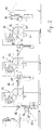
- the printing machine is used to print a web of material 10 from the roll. It has according to the usual row construction in the direction of the web 10 more printing units 12, 14, 16 in a row. In the figure, three printing units 12, 14, 16 are shown with format balancing rollers 18 in between. It is understood, however, that only two printing units 12, 14 and, as usual in multi-color printing, four and more printing units 12, 14, 16 in a row and format compensating rollers 18 of the same structure between successive printing units 12, 14, 16 may be provided. The printing machine shown in the figure can therefore be arbitrarily scaled in the number of printing units 12, 14, 16 and format compensating rollers 18.
- the printing press can optionally intermittently (see. Fig. 1 ) or continuously rotating (cf. Fig. 2 ) operate. All printing units 12, 14, 16 are alternately equipped with printing cylinders containing cartridges 20, 22 for the intermittent operation or the continuously rotating operation. The outer dimensions of both types of cassettes 20, 22 and their positioning and locking on the printing units 12, 14, 16 is the same. A cassette change can be made from both sides of the press.
- the invention shows an example of a printing machine for web offset printing with particular attention to the label printing.
- the invention is not limited to this printing technique and application. It can also be used on printing presses for flexographic printing, screen printing, gravure printing and the like. be realized.
- the printing cylinders for the intermittent as well as continuous rotating operation are a plate cylinder 24, a blanket cylinder 26 and an impression cylinder 28.
- the cylinders 24, 26, 28 of each cassette 20, 22 are of the same cylinder circumference corresponding to a maximum printing format of, for example 26 inch.
- the cylinder circumference is fixed.
- Blanket cylinder 26 and impression cylinder 28 are each arranged vertically above one another.
- cassette 20, 22 are the plate cylinder 24 in mating contact with the inking rollers 30 of an inking unit, which is of conventional construction and requires no further description.
- the cassette 20, 22 with the printing cylinders and the inking unit are the core components of a respective printing unit 12, 14, 16 associated printing tower.
- the blanket cylinder 26 for the continuously rotating operation (see. Fig. 2 ) is covered over at least approximately the full extent with blanket.
- the blanket is glued or stretched.
- the impression cylinder 28 for the continuously rotating operation is fully cylindrical. The surface of his coat goes over the full extent.
- the impression cylinder 28 for the intermittent operation (see.
- Fig. 1 is recessed circumferentially on the jacket. He has a cylindrical shell portion 32 of larger diameter, which merges at both ends radial steps 34 in a cylindrical shell portion 36 of smaller diameter.
- the sheath portion 32 of larger diameter occupies about sixteen twenty-sixth, and the sheath portion 36 of smaller diameter about ten twenty-sixth of the cylinder circumference.
- On the blanket cylinder 26 for the intermittent operation is attached to both ends of the clamping shafts 38, a printing blanket 40, which occupies about sixteenth twenty-sixth of the cylinder circumference.
- the blanket 40 has on the tension shafts 38 a sharp-edged waste. Between the tensioning shafts 38, the sheath 42 of the blanket cylinder 26 is free of about ten sixteenth of the cylinder circumference of printed blanket.
- the material to be printed web 10 passes through the gusset between blanket cylinder 26 and impression cylinder 28, which rotate in opposite directions.
- the running direction of the material web 10 is in the illustration from left to right.
- the printing process takes place in the contact zone of the material web 10 with the printing blanket 40 and the impression cylinder 28.
- Fig. 1 Take the blanket cylinder 26 and the impression cylinder 28 for intermittent operation an angular position to each other in, in which the clamping shafts 38 of the blanket cylinder 26 opposite the radial diameter steps 34 of the impression cylinder 28.
- the printing blanket 40 is over the full sixteen twenty-sixth of the circumference of the cylinder 26, 28 of the shell portion 32 of larger diameter of the impression cylinder 28 opposite.
- the non-printing free zone 42 of the blanket cylinder 26 is over the remaining ten twenty-sixth perimeter of the cylinder 26, 28 of the shell portion 36 of smaller diameter of the impression cylinder 28 opposite.
- the blanket cylinder 26 and the impression cylinder 28 rotate continuously.
- the web 10 is moved forward and printed, while the printing blanket 40 and the shell portion 32 of larger diameter of the impression cylinder 28 are opposite. If and as long as the web 10, however, between the blanket cylinder 26 and the shell portion 36 of smaller diameter of the impression cylinder 28 comes to rest, the printing process is interrupted and the web 10 is released for a return movement. After the return movement the printing process starts again. This results in the intermittent operation of the printing press.
- the full length of the blanket 40 is evidently utilized in the circumferential direction, i. H. printed the largest possible size.
- the blanket cylinder 26 and the impression cylinder 28 are adjusted relative to each other in the circumferential direction. It is then a part of the circumferential length of the blanket 40 of the shell portion 36 of smaller diameter of the impression cylinder 28 against. This part does not print. It prints only the complementary part of the circumferential length of the blanket 40, which is opposite to the shell portion 32 of larger diameter of the impression cylinder 28. As a result, a smaller format is printed.
- the largest possible size that can be printed corresponds to sixteen twenty-sixth of the circumferential length of blanket cylinder 26 and impression cylinder 28.
- the format can vary between eight-sixteenth and sixteenth twenty-sixth the circumferential length. It is understood that a certain non-printing circumferential length is needed for the return movement of the material web 10.
- Each printing unit 12, 14, 16 has a central main drive for the common rotary drive of the inking unit, the plate cylinder 24 and the blanket cylinder 26.
- the impression cylinder 28 is independently driven by a servo drive 44 in rotation. In printing operation, the rotation in the cylinder 24, 26, 28 is synchronous.
- the circumferential adjustment of blanket cylinder 26 and impression cylinder 28 for format adjustment is controlled controlled by the motor pressure motor.
- In response to a corresponding control signal with the servo drive 44 of the impression cylinder 28 is adjusted in the circumferential direction against the standing blanket cylinder 26.
- At least on a cassette system for the cylinder 26, 28 is unique.
- the web of material to be printed 10 is continuously unwound from a roll and the finished printed web 10 either wound continuously on a roll or cut.
- the printing units 12, 14, 16 of the web 10 as continuous, in the intermittent operation, however, with reciprocating movement of the web 10 through. This movement is effected with a vacuum feed roller 46 arranged on the input side in front of each printing unit 12, 14, 16 and a vacuum pull-out roller 48 arranged on the output side, which are driven in a reciprocating rotation.
- the required length compensation of the material web 10 takes place by looping before the first 12 and behind the last printing unit 16.
- the units serving for loop formation, the vacuum retraction and extraction rollers 46, 48 are bypassed and bypassed by the web 10.
- the material web 10 coming from the roll passes via an inlet roll 50 to the feed drum 52 of a web infeed driven in continuous rotation.
- a pressure roller 54 against the jacket of the feed drum 52 acts a pressure roller 54, the gusset formed with the feed drum 52 passes through the material web 10.
- the pressure roller 54 is rubber-covered. she can be with respect to the intake drum 52 electropneumatically switched on and off and thereby control in their pressing force.
- the web 10 passes to a guide roller 56, which is arranged at the top in a loop guide shaft 58.
- the material web 10 is guided over the deflection roller 56 when setting up the printing press.
- a looping of the material web 10 takes place in the loop guide shaft 58.
- the loop guide shaft 58 has a top and bottom open housing of rectangular outline, at the opposite inner walls, the web forming a loop 10 runs along. After looping, the guide roller 56 is no longer in contact with the material web 10.
- the loop guide shaft 58 has two photocells, which respond when the loop length falls below a predetermined minimum nominal length or exceeds a predetermined maximum nominal length.
- the loop guide shaft 58 can be adjusted for easy insertion of the material web 10 by hand in the machine longitudinal direction. This is dashed lines 58 'in the figure and indicated with respect to the adjustment direction by the arrow 60.
- a chicane 62 At the loop guide shaft is followed by a chicane 62 with five staggered successively arranged rollers, between which the web 10 is passed.
- the baffle 62 serves to calm the material web 10. Their rollers are driven in opposite directions to the material web feed in rotation, with a jacket speed, which exceeds the speed of the material web 10 during the return movement in the intermittent operation by about 20%.
- baffles are arranged at the back of the chicane 62 to the printing tower of the first printing unit 12 towards baffles. Furthermore, guide plates are provided on both sides of the rollers, which can be adjusted with threaded spindles individually by hand transversely to the direction of the web 10.
- the guide plates are provided with bores through which silicone (polyorganosiloxane) is injected by means of a timed pump via brushes arranged in the bores. The silicone prevents the label printing from the web 10 laterally exiting adhesive adheres to the rollers and the guide plates.
- the material web 10 passes to the vacuum feed roller 46 before the first printing unit 12. In intermittent operation, the web 10 is guided over the jacket of the driven in reciprocating rotation vacuum feed roller.
- the vacuum feed roller 46 is subdivided into five axially adjacent vacuum chambers, namely a central vacuum chamber and two outer vacuum chambers in a symmetrical arrangement on both sides thereof.
- the shell of the vacuum feed roller 46 is provided in the region of each chamber with numerous, distributed over the circumference axial longitudinal slots, which can be blown through for cleaning purposes in a suitable manner. This is done on a sixth chamber, which faces the five vacuum chambers in the circumferential direction.
- the jacket of the vacuum feed roller 46 is externally coated with ceramic.
- At the middle vacuum chamber of the vacuum feed roller 46 is constantly under pressure.
- the outer vacuum chambers are switched on, depending on the width of the web 10 if necessary.
- a rubber-based pressure roller 64 cooperates, which is electro-pneumatically with respect to the vacuum feed roller 46 and turned off and thereby controlled in their pressing force.
- the material web 10 coming from the chicane 62 passes through the gusset between the vacuum feed roller 46 and the pressure roller 64.
- the vacuum extraction roller 48 is identical to the vacuum retraction roller 46 and as they are driven in reciprocating rotation.
- a pressure roller 68 which corresponds in construction and function of the pressure roller 64.
- the vacuum feed roller 46 is mounted stationary.
- the vacuum extraction roller 48 is mounted laterally by means of a guide block about ⁇ 1 mm horizontally adjustable to adjust them with respect to the vacuum feed roller 46 can.
- a format compensating roller 18 is arranged, which is wrapped by the material web 10.
- the format compensating roller 18 of the format repeat between the printing units 12, 14 is set.
- the format compensating roller 18 is arranged rotatably, in particular so locked against turning with the web 10. It consists of a hollow cylinder, which is distributed over half its circumference, provided axial longitudinal slots and coated on the surface with microporous, air-permeable sintered metal.
- the hollow cylinder is provided at its two end faces with connections for compressed air. Their pressure is regulated.
- the half-side of the hollow cylinder, at which the air escapes, is looped around in intermittent operation by the material web 10.
- the format compensating roller 18 is mounted on both sides in load cells.
- the load cells can be adjusted independently with gear motor actuated ball screw Hubspindelantrieben in the direction of the vacuum rollers 46, 48 of the adjacent printing units 12, 14 and away.
- the motors are equipped with encoders. Your respective one Angle of rotation is the format-dependent predetermined loop length controlled electronically.
- the format compensation roller 18 is positioned with the ball screw Hubspindelantrieben depending on the format repeat.
- the compressed air emerging from the sintered metal forms between the format compensating roll 18 and the material web 10 an air cushion of ⁇ thickness, which generates a well-defined tension in the material web 10.
- By the Passerregelung resulting voltage changes in the web 10 are recorded with the load cells and corrected with the ball screw Hubspindelantrieben.
- a path sensor 74 is attached to the side of the printing press. If the material web 10 runs away to the side, which is detected by the web sensor 74, which outputs a control signal to the corresponding ball screw Hubspindelantrieb and corrects the web run by inclination of the format compensating roller 18. Alternatively, the web run can be stabilized with lateral guide plates.
- the web 10 After passing through the second printing unit 14, the web 10 again passes to a format compensating roller 18, the following printing unit 16, etc to the vacuum extraction roller 48 of the last printing unit 16 is followed by serving for loop deflection roller 76 and a loop guide shaft 78, the structure and Adjustability which corresponds to the inlet of the printing press. After looping is also the guide roller 76 with the web 10 is no longer in contact.
- the emerging from the loop guide shaft 78 web 10 passes through a chicane 80 to the pullout drum 82 a web statement.
- the structure of the chicane 80 corresponds to the chicane 62 on the web feed of the printing press.
- a rubber-based pressure roller 84 presses the material web 10 with a controlled pressing force against the jacket of the pullout drum 82.
Applications Claiming Priority (1)
| Application Number | Priority Date | Filing Date | Title |
|---|---|---|---|
| DE102009021515A DE102009021515A1 (de) | 2009-05-15 | 2009-05-15 | Druckmaschine |
Publications (2)
| Publication Number | Publication Date |
|---|---|
| EP2251196A2 true EP2251196A2 (fr) | 2010-11-17 |
| EP2251196A3 EP2251196A3 (fr) | 2011-05-25 |
Family
ID=42537785
Family Applications (1)
| Application Number | Title | Priority Date | Filing Date |
|---|---|---|---|
| EP10005012A Withdrawn EP2251196A3 (fr) | 2009-05-15 | 2010-05-12 | Presse d' impression |
Country Status (2)
| Country | Link |
|---|---|
| EP (1) | EP2251196A3 (fr) |
| DE (1) | DE102009021515A1 (fr) |
Cited By (1)
| Publication number | Priority date | Publication date | Assignee | Title |
|---|---|---|---|---|
| JP2020146941A (ja) * | 2019-03-14 | 2020-09-17 | 株式会社ミヤコシ | 間欠印刷機 |
Citations (5)
| Publication number | Priority date | Publication date | Assignee | Title |
|---|---|---|---|---|
| DE3445013A1 (de) | 1983-12-09 | 1985-06-20 | Rengo Co., Ltd., Osaka | Druckmaschine |
| DE3832891A1 (de) | 1987-09-30 | 1989-05-03 | Ryobi Ltd | Offset-druckmaschine zum drucken einer kontinuierlichen bahn |
| EP0415881A2 (fr) | 1989-08-30 | 1991-03-06 | De La Rue Giori S.A. | Machine rotative d'impression combinée, particulièrement pour imprimer les papiers de valeur |
| DE10307089A1 (de) | 2002-10-19 | 2004-05-13 | Koenig & Bauer Ag | Bauteile einer Druckmaschine |
| EP1935642A1 (fr) | 2005-08-30 | 2008-06-25 | Rotatek, S.A. | Cassette de rouleaux pour machines semi-rotatives pouvant etre inseree dans des unites d'impression pour offset |
Family Cites Families (3)
| Publication number | Priority date | Publication date | Assignee | Title |
|---|---|---|---|---|
| DE10311219A1 (de) * | 2003-03-14 | 2004-09-30 | Werner Kammann Maschinenfabrik Gmbh | Verfahren und Vorrichtung zum Bedrucken einer Bahn |
| DE10322521A1 (de) * | 2003-05-19 | 2004-12-23 | Voith Paper Patent Gmbh | Bahnführungs- und/oder Dichtungseinrichtung |
| DE202004021518U1 (de) * | 2004-09-09 | 2008-09-04 | Koenig & Bauer Aktiengesellschaft | Druckmaschinen |
-
2009
- 2009-05-15 DE DE102009021515A patent/DE102009021515A1/de not_active Withdrawn
-
2010
- 2010-05-12 EP EP10005012A patent/EP2251196A3/fr not_active Withdrawn
Patent Citations (5)
| Publication number | Priority date | Publication date | Assignee | Title |
|---|---|---|---|---|
| DE3445013A1 (de) | 1983-12-09 | 1985-06-20 | Rengo Co., Ltd., Osaka | Druckmaschine |
| DE3832891A1 (de) | 1987-09-30 | 1989-05-03 | Ryobi Ltd | Offset-druckmaschine zum drucken einer kontinuierlichen bahn |
| EP0415881A2 (fr) | 1989-08-30 | 1991-03-06 | De La Rue Giori S.A. | Machine rotative d'impression combinée, particulièrement pour imprimer les papiers de valeur |
| DE10307089A1 (de) | 2002-10-19 | 2004-05-13 | Koenig & Bauer Ag | Bauteile einer Druckmaschine |
| EP1935642A1 (fr) | 2005-08-30 | 2008-06-25 | Rotatek, S.A. | Cassette de rouleaux pour machines semi-rotatives pouvant etre inseree dans des unites d'impression pour offset |
Cited By (5)
| Publication number | Priority date | Publication date | Assignee | Title |
|---|---|---|---|---|
| JP2020146941A (ja) * | 2019-03-14 | 2020-09-17 | 株式会社ミヤコシ | 間欠印刷機 |
| CN111688352A (zh) * | 2019-03-14 | 2020-09-22 | 株式会社宫腰 | 间歇印刷机 |
| EP3711952A1 (fr) * | 2019-03-14 | 2020-09-23 | Miyakoshi Printing Machinery Co., Ltd. | Appareil d'impression intermittent |
| JP7088556B2 (ja) | 2019-03-14 | 2022-06-21 | 株式会社ミヤコシ | 間欠印刷機 |
| CN111688352B (zh) * | 2019-03-14 | 2022-08-16 | 株式会社宫腰 | 间歇印刷机 |
Also Published As
| Publication number | Publication date |
|---|---|
| DE102009021515A1 (de) | 2010-11-25 |
| EP2251196A3 (fr) | 2011-05-25 |
Similar Documents
| Publication | Publication Date | Title |
|---|---|---|
| EP0415881B1 (fr) | Machine rotative d'impression combinée, particulièrement pour imprimer les papiers de valeur | |
| EP2714408B2 (fr) | Machine d'impression et procédé de contrôle de la tension | |
| EP2734375B1 (fr) | Presse rotative | |
| EP0415882B1 (fr) | Rouleaux tendeurs pour une machine rotative d'impression | |
| EP2352643B1 (fr) | Presse a bobines a trajet vertical d'un marche d'une bande, sechage et mise en tension en sens travers | |
| DE102013223826B4 (de) | Tiefdruckmaschinen und Druckanlage mit einer Tiefdruckmaschine | |
| DE102009002580A1 (de) | Druckmaschine, insbesondere Bogenoffsetdruckmaschine | |
| EP2928695B1 (fr) | Presse rotative | |
| EP2072251A2 (fr) | Mécanismes de mouillage | |
| AT408633B (de) | Druckeinrichtung zum bedrucken von plastik-karten | |
| WO2016180617A1 (fr) | Groupe d'impression et procédé permettant de faire fonctionner un système de racle dans un groupe d'impression | |
| DE102012208840A1 (de) | Druckmaschine | |
| WO2016180615A1 (fr) | Machine permettant le traitement et/ou la transformation en plusieurs étages de matières à imprimer en forme de feuilles, ainsi qu'installation et procédé de production de produits imprimés à partir de matières à imprimer en forme de feuilles | |
| EP2251196A2 (fr) | Presse d' impression | |
| DE102004043681A1 (de) | Druckmaschine | |
| WO2014012722A1 (fr) | Presse rotative offset à module de vernissage et procédé d'impression et de vernissage d'une bande de matériau | |
| EP2251197A2 (fr) | Presse d'impression | |
| EP2251198A2 (fr) | Presse d'impression | |
| DE102017203560B4 (de) | Druckmaschine | |
| EP2697069B1 (fr) | Machine à imprimer | |
| WO2009144106A1 (fr) | Guidage de feuille dans un dispositif de gaufrage | |
| DE3907366A1 (de) | Vorrichtung zum drucken im offsetdruckverfahren | |
| DE3131168A1 (de) | "rollenrotationsdruckmaschine" | |
| DE202004021518U1 (de) | Druckmaschinen | |
| EP0463343A2 (fr) | Machine d'impression |
Legal Events
| Date | Code | Title | Description |
|---|---|---|---|
| PUAI | Public reference made under article 153(3) epc to a published international application that has entered the european phase |
Free format text: ORIGINAL CODE: 0009012 |
|
| AK | Designated contracting states |
Kind code of ref document: A2 Designated state(s): AL AT BE BG CH CY CZ DE DK EE ES FI FR GB GR HR HU IE IS IT LI LT LU LV MC MK MT NL NO PL PT RO SE SI SK SM TR |
|
| AX | Request for extension of the european patent |
Extension state: BA ME RS |
|
| PUAL | Search report despatched |
Free format text: ORIGINAL CODE: 0009013 |
|
| AK | Designated contracting states |
Kind code of ref document: A3 Designated state(s): AL AT BE BG CH CY CZ DE DK EE ES FI FR GB GR HR HU IE IS IT LI LT LU LV MC MK MT NL NO PL PT RO SE SI SK SM TR |
|
| AX | Request for extension of the european patent |
Extension state: BA ME RS |
|
| RIC1 | Information provided on ipc code assigned before grant |
Ipc: B41F 13/02 20060101ALI20110418BHEP Ipc: B65H 23/00 20060101ALI20110418BHEP Ipc: B41F 13/04 20060101ALI20110418BHEP Ipc: B41F 7/04 20060101AFI20100813BHEP |
|
| STAA | Information on the status of an ep patent application or granted ep patent |
Free format text: STATUS: THE APPLICATION IS DEEMED TO BE WITHDRAWN |
|
| 18D | Application deemed to be withdrawn |
Effective date: 20111126 |