EP2249929B1 - Energieabsorbierende rettungsleinensysteme - Google Patents
Energieabsorbierende rettungsleinensysteme Download PDFInfo
- Publication number
- EP2249929B1 EP2249929B1 EP09715921.4A EP09715921A EP2249929B1 EP 2249929 B1 EP2249929 B1 EP 2249929B1 EP 09715921 A EP09715921 A EP 09715921A EP 2249929 B1 EP2249929 B1 EP 2249929B1
- Authority
- EP
- European Patent Office
- Prior art keywords
- hub
- lifeline
- drum assembly
- flange
- web
- Prior art date
- Legal status (The legal status is an assumption and is not a legal conclusion. Google has not performed a legal analysis and makes no representation as to the accuracy of the status listed.)
- Active
Links
- 230000007246 mechanism Effects 0.000 claims description 21
- 230000002093 peripheral effect Effects 0.000 claims description 15
- 230000001133 acceleration Effects 0.000 claims description 6
- 239000000463 material Substances 0.000 description 15
- 238000010521 absorption reaction Methods 0.000 description 14
- 229910001220 stainless steel Inorganic materials 0.000 description 8
- 239000010935 stainless steel Substances 0.000 description 8
- 229910052751 metal Inorganic materials 0.000 description 7
- 239000002184 metal Substances 0.000 description 7
- 238000000034 method Methods 0.000 description 6
- 229910000639 Spring steel Inorganic materials 0.000 description 4
- 208000027418 Wounds and injury Diseases 0.000 description 4
- 230000006378 damage Effects 0.000 description 4
- 238000006073 displacement reaction Methods 0.000 description 4
- 230000002517 constrictor effect Effects 0.000 description 3
- 230000000694 effects Effects 0.000 description 3
- 239000004743 Polypropylene Substances 0.000 description 2
- 238000007792 addition Methods 0.000 description 2
- 229910052782 aluminium Inorganic materials 0.000 description 2
- XAGFODPZIPBFFR-UHFFFAOYSA-N aluminium Chemical compound [Al] XAGFODPZIPBFFR-UHFFFAOYSA-N 0.000 description 2
- 238000004873 anchoring Methods 0.000 description 2
- 229920001577 copolymer Polymers 0.000 description 2
- 230000005489 elastic deformation Effects 0.000 description 2
- 208000014674 injury Diseases 0.000 description 2
- 239000004033 plastic Substances 0.000 description 2
- -1 polypropylene Polymers 0.000 description 2
- 229920001155 polypropylene Polymers 0.000 description 2
- 238000012360 testing method Methods 0.000 description 2
- 239000006096 absorbing agent Substances 0.000 description 1
- 230000000712 assembly Effects 0.000 description 1
- 238000000429 assembly Methods 0.000 description 1
- 238000004891 communication Methods 0.000 description 1
- 230000001010 compromised effect Effects 0.000 description 1
- 230000003247 decreasing effect Effects 0.000 description 1
- 238000010586 diagram Methods 0.000 description 1
- 230000005484 gravity Effects 0.000 description 1
- 230000003993 interaction Effects 0.000 description 1
- 230000002452 interceptive effect Effects 0.000 description 1
- 238000004519 manufacturing process Methods 0.000 description 1
- 239000007769 metal material Substances 0.000 description 1
- 238000012986 modification Methods 0.000 description 1
- 230000004048 modification Effects 0.000 description 1
- 230000009467 reduction Effects 0.000 description 1
Images


Classifications
-
- A—HUMAN NECESSITIES
- A62—LIFE-SAVING; FIRE-FIGHTING
- A62B—DEVICES, APPARATUS OR METHODS FOR LIFE-SAVING
- A62B35/00—Safety belts or body harnesses; Similar equipment for limiting displacement of the human body, especially in case of sudden changes of motion
- A62B35/0093—Fall arrest reel devices
Definitions
- the present invention relates to lifeline systems and, particularly, to self-retracting lifeline systems including an energy absorbing mechanism or system.
- a housing or cover provides enclosure/protection for the internally housed components.
- the housing includes attached thereto a connector for anchoring the self-retracting lifeline to either the user or to a fixed anchor point.
- the connector must be capable of withstanding forces required to stop a falling body of a given mass in a given distance.
- a drum or spool around which a lifeline is coiled or spooled rotates within the housing.
- the drum is typically under adequate rotational tension to reel up excess extended lifeline without hindering the mobility of the user.
- the drum is formed to withstand forces necessary to stop a falling body of a given mass in a given distance.
- the lanyard or lifeline is attached at one end thereof to the drum to allow the drum to reel in excess lifeline.
- the lifeline is attached at the other end thereof to either the user or to an anchorage point, whichever is not already attached to the housing.
- Self-retracting lifeline systems also include a mechanism which locks (that is, prevents rotation of) the drum assembly of the self-retracting lifeline upon indication that a fall is occurring. For example, when the rope, cable or web being pulled from the self- retracting lifeline system causes the drum assembly to rotate above a certain angular velocity or experience an angular acceleration above a certain level, a brake mechanism can cause the drum assembly to suddenly lock.
- the operational components of self-retracting lanyard are typically manufactured from high-strength materials such as stainless steel to ensure locking, while withstanding the stresses associated therewith.
- high-strength materials such as stainless steel
- some mechanism or method is typically used to absorb at least some of the energy of the fall.
- the web itself has extra convolutions or folds that are held together by stitching which tears out to absorb energy.
- Other self-retracting lifelines use friction brake mechanisms to absorb the energy.
- Many mechanisms and/or methods of energy absorption used in currently available self-retracting lifelines require additional parts or assembly steps during manufacture which add cost, bulk and/or complexity to the self-retracting lifelines.
- a known energy absorber is described for instance in JP3011404U .
- the present invention provides a lifeline system as set out in the appended claims.
- the self-retracting lifeline of the present invention includes a hub which can deform to absorb energy. No extra components, extra parts or extra assembly steps are required to achieve such energy absorption.
- the self-retracting lifeline of the present invention can provide an increase in reliability as compared to certain currently available self-retracting lifelines while reducing complexity, bulk and/or cost.
- FIG. 1 illustrates one embodiment of a self-retracting lifeline system 10 of the present invention wherein an outside cover or housing 20 is shown schematically in dashed lines.
- cover 20 which can, for example, be formed in two halves as known in the art
- self-retracting lifeline system 10 can, for example, be connected via a connector 30 to some fixed object.
- a distal end 44 of lifeline 40 (for example, a polymeric web material as known in the art) can, for example, be connected to a harness 400 worn by the user 5 (see Figure 1 ).
- connector 30 can be connected to the user (for example, to D-ring 410 via a snap ring or carabiner 500) and distal end 44 of lifeline 40 can be attached to some fixed object.
- Figure 2 illustrates components of self-retracting lifeline system 10 in a disassembled state. Housing 20 is excluded in Figure 2 .
- a number of components rotate relative to frame members 50 and 60 about a shaft 70.
- frame members 50 and 60 and shaft 70 were formed, for example, from a metal such as stainless steel.
- Shaft 70 rotates within shaft bushings 80 that are seated within holes 52 and 62 of frame members 50 and 60, respectively.
- Retainers such as snap rings 90 cooperate with seatings 72 formed within shaft 70 to retain shaft 70 in rotatable connection with bushings 80.
- a hub or drum assembly 100 includes a first hub flange or plate 110, a hub or drum 120 around which lifeline web 40 is coiled, a web sleeve 130 (see, for example, Figure 4 ), a second hub flange 140, and connectors such as screws 150.
- hub plate 110 and hub flange 140 were formed from a metal such as aluminum or stainless steel, while hub or drum 120 was formed at least partially from a deformable material such as a polymeric material as described further below. When assembled, hub plate 110, hub 120, hub flange 140, and screws 150 form hub or drum assembly 100 which rotates on shaft 70.
- a loop end 42 of the lifeline web 40 surrounds web sleeve 130 (which is positioned with a passage 123 formed within hub 120; see, for example, Figure 4 ) and shaft 70, thereby anchoring loop end 42 securely within drum assembly 100.
- loop end 42 extends through a slot 121 formed in hub 120 (in connection or communication with passage 123; see, for example, Figures 5A-5D ) and a portion of lifeline web 40 is coiled around hub 120, leaving a free end 44 which extends from housing 20 and attaches to the user through suitable hardware (for example, through an end connector as known in the art which cooperates with connector 500 and D-ring 410).
- free end 44 can attach to some fixed point while self-retracting lanyard system 10 is attached to the user as described above.
- a power spring assembly 160 can include a conventional coiled strap of spring steel (not illustrated in detail in Figures 1 and 2 ) inside a plastic housing. One end of the spring steel strap can be anchored to housing 20. The other end can engage a slot 76 in shaft 70.
- the housing of power spring assembly 160 can be rotationally locked to frame 60 by a stud 164 on the housing engaging a hole 64 in frame 60.
- lifeline web 40 is anchored to and coiled around hub 120.
- the power spring is "wound up” to provide torque to shaft 70 and thus to hub 120 or drum assembly 100.
- the torque applied to shaft 70 pre-tensions lifeline web 40 and causes lifeline web 40 to coil up or retract around hub 120 after it has been uncoiled therefrom (that is, pulled out or extended from housing 20).
- Self-retracting lifeline system 10 can also include a braking mechanism as known in the art.
- self-retracting lifeline system 10 includes a braking mechanism.
- a catch pivot 170 can be mounted in and extend through hub plate/catch base 110 to provide a pivot for a catch bushing 180 and a catch 190 (at a point in the vicinity of or at the center of mass of catch 190).
- the braking mechanism can also include a generally V-shaped catch spring 200 having one end which engages a hole in the hub plate/catch base 110 and another end which engages a hole in catch 190.
- the force exerted by the catch spring 200 can be balanced against the rotational inertia of catch 190 so that catch 190 actuates to effect braking only when lifeline web 40 is being pulled from self-retracting lifeline system 10 at an acceleration rate corresponding to the beginning of a fall.
- the catch/catch spring assembly can be designed to actuate when the web is being pulled out at 1/2 or 3/4 times the acceleration of gravity. For lower accelerations or when the user is extending the web at a constant rate, such as when walking, hub assembly 100 turns freely.
- FIGs 3A through 7 illustrated details of one embodiment of hub or drum assembly 100 of the present invention.
- hub assembly 100 can be used in connection with many types of self-retracting lifeline systems.
- Self-retracting lifeline system 10 illustrated in Figures 1 and 2 is set forth as a representative example only.
- the components of hub assembly 100 are set forth generically and may not include some of the specific elements described in connection with Figures 1 and 2 to operate in connection with self-retracting lifeline system 10.
- FIGS 3A through 3C illustrate drum assembly 100 in an assembled state
- Figure 4 illustrates drum assembly 100 in a disassembled or exploded state
- drum assembly 100 includes hub plate 110, hub or drum 120 around which lifeline web 40 is coiled, web sleeve 130 (see, for example, Figure 4 ), hub flange 140, and connectors such as screws 150.
- one or more connectors or screws 150 can be passed through passages 142 in hub flange 140, through passages 122 in hub 120 and through passages 112 in hub plate 110.
- At least passages 112 can, for example, include cooperating threading to retain screws 150 in operative connection therewith.
- hub plate 110, hub 120, hub flange 140, and screws 150 form drum assembly 100, which rotates on shaft 70.
- Each of hub flange or plate 110 and hub flange 140 can, for example, have a radius/diameter larger than hub 120 to, for example, assist in or guide the coiling of lifeline web 40 around hub 120.
- FIG 4 three complete coils or revolutions of lifeline web 40 around hub 120 are illustrated.
- the energy absorbing function of the hub or drum assemblies of the present invention will operate with more coils or as few as one coil.
- a braking mechanism when actuated, locks drum assembly 100 to prevent its rotation on shaft 70 in the event of a fall. After drum assembly 100 is locked, hub 120 can deform to absorb energy as described below.
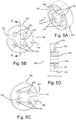
- FIG. 5A through 5D illustrate enlarged views of hub 120.
- Hub 120 (which can, for example, be molded from an integral piece of a polymeric material such as, for example, copolymer polypropylene) includes a peripheral or perimeter member 124, which forms the outer surface or perimeter of hub 120.
- Web lifeline 40 is coiled around peripheral or perimeter member 124 which facilitates smooth coiling and uncoiling of lifeline web 140 therearound when lifeline 40 extends and retracts during normal, non-locked use.
- hub 120 also included an intermediate connector or septum 126 extending (for example, generally in the middle of hub 120) radially between peripheral member 124 and a shaft connecting or generally central portion of hub 120. The thickness of septum 126 assists in adjusting or determining the energy absorption afforded by hub 120 as described further below.
- septum 126 is a continuous member.
- hub 120 (which had a generally circular/cylindrical cross-section over most of the perimeter thereof) had a radius of approximately 1.18 inches.
- peripheral member 124 included an area of non-circular cross-sectional shape to accommodate an area of the webbing of lifeline 40 which was doubled over on itself and stitched to create loop 42 (see, for example, Figure 6 ) so that the outer coils of lifeline 40 around hub 120 would be of generally circular cross-sectional shape.
- FIG. 6 illustrates drum assembly 100 with screws 150 and hub flange 140 hidden. It is assumed that just prior to drum assembly 100 locking, a weight (for example, 250 pounds corresponding to the weight of a user) attached to free end 44 of lifeline web 40 was in a nearly free-fall condition and had accumulated substantial kinetic energy. At the instant illustrated in Figure 6 , drum assembly 100 has locked and tension in lifeline web 40 is rapidly increasing, causing the coils of lifeline web 40 to constrict around hub 120. In the illustrated embodiment, at a certain tension level, determined, for example, in large part by the thickness (and/or other properties) of septum 126, hub 120 will begin to crush as a result of the radial forces acting upon it.
- a weight for example, 250 pounds corresponding to the weight of a user
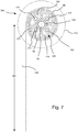
- FIG. 7 illustrates drum assembly 100, once again, with screws 150 and hub flange 140 hidden.
- hub 120 has deformed (for example, reduced in outside diameter).
- the deformed hub shape illustrated is an approximation. Forces on septum 126 have caused it to deform (variously buckle, compress, or stretch, depending on the region of hub 120).
- Outside peripheral member 124 has also deformed (for example, buckled and folded) as a result of the reduction of perimeter.
- the net effect of the deformation (buckling, compressing, etc.) is that kinetic energy is absorbed as the falling weight was gradually brought to a halt.
- the number of coils of web lifeline 40 around hub 120 affects the displacement and the maximum web tension. In that regard, if there were more web coils on hub 120, the maximum web tension would be less but the displacement would be greater, yielding roughly the same energy absorption. Further, fewer coils would produce a greater maximum web tension while having less displacement, again, with roughly the same energy absorption.
- Hub 120 will provide energy absorption as described above if the falling weight is attached to distal end 44 of web lifeline 40 as well as if distal end 44 of web lifeline 40 is attached to a fixed object/anchor point. Furthermore, it is also understood that energy absorbing hub 120 will also operate to absorb energy if a rope, a cable or other extending member is used for the lifeline rather than a web material as described herein as a representative example.
- hub 120 is formed from a deformable material that deforms to absorb energy.
- hub 120 includes a septum 126 having a thickness that can be adjusted to fine tune energy absorption. In that regard, for a particularly case, if septum 126 is too thin, the force required to crush it will be too small, resulting in too little energy absorption. If, for a particular case, septum 126 is too thick, the force required to crush it will be too great, and again the resultant energy absorption will be too small.
- One skilled in the art can readily establish a proper thickness for to achieve desired energy absorption using established engineering principles and methodologies. As clear to one skilled in the art, many other hub configurations can also be used.
- Non-elastic deformation of a material is one example of an energy absorption methodology. Energy absorption via an elastic deformation or a combination of elastic and non-elastic deformation is also possible.
- hub 120 deforms under, for example, the tensions/forces experienced upon braking in a fall as described above.
- hub plate 110 a first lateral flange
- hub flange 140 a second lateral flange
- hub 120 is attached to hub plate 110 and hub flange 140 so that hub 120 can deform independently of any deformation of hub plate 110 and hub flange 140.
- hub plate 110 and hub flange 140 and/or other components of self-retracting lifeline system 10 need not be connected to hub 120 or in locked, rotating connection with shaft 70.
- drum assembly 100 remains rotatable about shaft 70 and can, for example, still operate to retract lifeline web 40 upon removable of extending force thereon) even after a fall and the associated deformation of hub 120 in accordance, for example, with the ANSI Z359.1 Standard and the Canadian Standards Association (CSA) Z259.2.2 Standard.
- CSA Canadian Standards Association
- at least a portion of septum 126 and a portion of peripheral member 124 can deform, while a generally central portion or flange connecting portion of hub 120 around passage 123 remains substantially or completely undeformed to facilitate rotation of hub or drum assembly 100 with shaft 70 after deformation of radially outward portions of hub 120 (without deformation of adjacent components such as hub plate 110 and hub flange 120).
- the central portion of hub 120 can, for example, be strengthened via, for example, increased material thickness or other structural techniques as known in the art.
- the central portion of hub 120 can also be formed of a material different from (for example, stronger than) the deforming portion of hub 120.
- the periphery of passages 122 and passage 123 are formed to have increased thickness such that generally no deformation of the central portion of hub 120 occurs.
- hub plate 110 and hub flange 140 are in operative connection with the central portion of hub 120 (via passages 122 and screws 150), little or no force tending to deform hub plate 110 or hub flange 140 are transferred to hub plate 110 or hub flange 140.
- Hub plate 110 and hub flange 140 can, for example, be formed of a polymeric material or of a metal material.
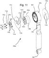
- FIGS 8 through 13B illustrates another embodiment of a self-retracting lifeline system 10a of the present invention which operates in a similar manner to self-retracting lifeline system 10.
- like elements of system 10a are designated similarly to corresponding elements of system 10 with the addition of the designation "a" thereto.
- a cover is formed via connection of two housing members 20a and serves to protect internal mechanisms of self-retracting lifeline 10a from damage.
- Self-retracting lifeline 10a can, for example, be connected via a connector 30a to some fixed object.
- a distal end 44a of lifeline 40 (for example, a polymeric web material as known in the art) can, for example, be connected to a harness 400 worn by the user 5 (see Figure 1 ).
- connector 30a can be connected to the user (for example, to D-ring 410 via a snap ring or carabiner 500) and distal end 44a of lifeline 40a can be attached to some fixed object.
- Figure 9 illustrates components of self-retracting lifeline system 10a in a disassembled or exploded state.
- a number of components of system 10a rotate relative to frame members 50a and 60a about a shaft 70a.
- frame members 50a and 60a are formed integrally as part of a U-shaped length of metal (for example, stainless steel).
- Shaft 70a (formed, for example, from a metal such as stainless steel) rotates within bushings 80a positioned with passages 52a and 62a of frame members 50a and 60a, respectively.
- a flanged retainer such as a threaded member 92a cooperates with a threaded passage 73a formed in one end of shaft 70a to retain shaft 70a in rotatable connection with frame members 50a and 60a.
- a flange 71a on the other end of shaft 70a can, for example, abut frame member 60a.
- Hub or drum assembly 100a of system 10a includes a first hub flange or hub plate 110a, a hub or drum 120a around which lifeline web 40a is coiled, a second hub flange 140a, and connectors such as screws 150a (which are oriented in the opposite direction as screws 150 of system 10).
- hub plate 110a and hub flange 140a were formed from a metal such as aluminum or stainless steel, while hub 120a was formed from a deformable polymeric material as described above. When assembled, hub plate 110a, hub 120a, hub flange 140a, and screws 150a form hub or drum assembly 100a which rotates on shaft 70a.
- Hub 120a is of decreased diameter and increased width as compared to hub 120 to accommodate a lifeline web that is approximately 25 mm wide (as compared to hub 120a, which is designed for use with webbing that is approximately 17 mm wide).
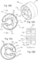
- a loop end 42a of the lifeline is positioned with a passage 123a (see, for example, Figures 12A-12D ) formed within hub 120a around shaft 70a to anchor loop end 42a securely within drum assembly 100a. Loop end 42a extends through a slot 121a formed in hub 120a and a portion of lifeline web 40a is coiled around hub 120a, leaving a free end 44a which extends from housing 20.
- Lifeline web 40a also includes an energy absorbing portion or section 46a in which, for example, a length of lifeline web 40a is folded back upon itself and sewn or stitched together as know in the fall protection arts. In the case of a fall, the stitching of the energy absorbing portion 46a tears to absorb energy.
- Shaft 70a is rotationally locked to hub plate 110 via a catch or braking base 112a (formed, for example, from a metal such as case stainless steel) that is connected to hub plate 110a by screws 150a.
- braking base 112a includes a passage 113a formed therein through which shaft 70a passes and a radially inward projecting member 114a which engages a radially outward portion of slot 76a of hub plate 110.
- Tension is applied to drum assembly 100a to retract lifeline 40a after extension thereof via a power spring assembly 160a including coiled strap of spring steel 162a inside a plastic housing formed by housing members 168a.
- a radially outward end 163a of spring steel strap can be anchored to frame 60a.
- a radially inward end 163a' can engage a radially inward, narrow portion of slot 76a in shaft 70a.
- One housing member 168a of power spring assembly 160 can, for example, be rotationally locked to frame 60 by a projecting member or stud 164a on housing member 168a which engages an abutment member 64a formed in frame 60a.
- lifeline web 40a is anchored to and coiled around hub 120a of drum assembly 100a.
- power spring 162a is "wound up” to provide torque to shaft 70a and thus to drum assembly 100a.
- the torque applied to shaft 70a pre-tensions lifeline web 40 and causes lifeline web 40 to coil up or retract around hub 120a after it has been uncoiled therefrom as described above in connection with self-retracting lanyard system 10.
- Self-retracting lifeline system 10a also includes a braking mechanism. Like self-retracting lifeline system 10, self-retracting lifeline system 10a can, for example, include a braking mechanism.
- a catch 190a (formed, for example, from a metal such as cast stainless steel) is pivotably or rotatably mounted (eccentric to the axis of shaft 70a) to catch base 112a via a partially threaded pivot member 180a which passes through a passage 192a formed in catch 190a to connect to a threaded passage 116a on catch base 110a.
- the axis of threaded pivot member 180a (and passage 192a) preferably corresponds approximately or generally to the center of mass of catch 190a.
- pivot member is preferably positioned in the vicinity of the center of mass of catch 190a and preferably as close to the center of mass as possible.
- the braking mechanism can also include a catch spring 200 having one end which engages a connector 117a (for example, a loop or passage) of catch base 112a and another end which engages a connector 194a (for example, a loop or passage) of catch 190a.
- catch spring 200a The force exerted by the catch spring 200a is generally balanced against the rotational inertia of catch 190a so that catch 190a actuates (via centrifugal force) to effect braking only when lifeline web 40a is being pulled from self-retracting lifeline system 10a at an acceleration rate corresponding, for example, to the beginning of a fall as described above in connection with system 10.
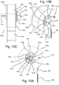
- FIGS 10A through 13 illustrated details hub or drum assembly 100a.
- drum assembly 100a can be used in connection with many types of self-retracting lifeline systems.
- Screws 150a are passed through passages 118a in catch base 112a, passages 111a hub plate 110a, through passages 122a in hub 120a and through passages 142a in hub flange 140a to retain drum assembly 100a and catch base 112a in operative connection.
- hub 120a can, for example, be molded from an integral piece of a polymeric material such as, for example, copolymer polypropylene.
- Hub 120a includes a peripheral or perimeter member 124a which forms the outer surface or perimeter of hub 120a.
- Web lifeline 40 is coiled around peripheral or perimeter member 124a which facilitates smooth coiling and uncoiling of lifeline web 140a therearound when lifeline 40a extends and retracts during normal, non-locked use.
- hub 120a also includes an intermediate connector such as a septum 126a extending between peripheral member 124a and a radially inward or generally central portion of hub 120a. Once again, the thickness (and/or other properties) of septum 126a assists in adjusting or determining the energy absorption afforded by hub 120a as described in connection with hub 120.
- FIG 13A illustrates drum assembly 100a with screws 150a and hub flange 140a hidden. It is assumed that just prior to drum assembly 100a locking, a weight (for example, 250 pounds (113.4 kg) corresponding to the weight of a user) attached to free end 44a of lifeline web 40a was in a nearly free-fall condition and had accumulated substantial kinetic energy. At the instant illustrated in Figure 13A , drum assembly 100a has locked and tension in lifeline web 40a is rapidly increasing, causing the coils of lifeline web 40a to constrict around hub 120a. At a certain tension level, determined, for example, in large part by the thickness of septum 126a, hub 120a will begin to crush as a result of the radial forces acting upon it (see Figure 13B ).
- a weight for example, 250 pounds (113.4 kg) corresponding to the weight of a user
- Comparison of Figure 13A and 13B illustrates the deformation of hub 120a to absorb energy in a manner similar to that described in connection with hub 120.
- a generally central portion or flange connecting portion of hub 120a around passage 123 remains substantially or completely undeformed to facilitate rotation of hub or drum assembly 100a after energy absorbing deformation of at least a portion of hub 120a.
- FIG. 14 A diagram of the testing system is set forth in Figure 14 .
- a force measuring instrument 1 is used to measure a force resulting from a free drop of a mass 3 of 100 kg.
- self-retracting lifeline systems 4 were subjected to a drop a distance H (not exceeding 2 m or approximately 6.56 feet; as measured from a clip or connector mechanism 2 attaching mass 4 to self-retracting lifeline system 4) with 100 kg (approximately 220 pounds) mass 3 as provided in the standards.
- the resulting peak fall arrest force (PFAF) or braking force was approximately 1,100 pounds-force (4.89 kN), which is less than the limit of 1,349 pounds-force (6 kN) set forth in EN 364.
Landscapes
- Health & Medical Sciences (AREA)
- General Health & Medical Sciences (AREA)
- Business, Economics & Management (AREA)
- Emergency Management (AREA)
- Emergency Lowering Means (AREA)
- Storage Of Web-Like Or Filamentary Materials (AREA)
- Wind Motors (AREA)
Claims (9)
- Rettungsleinensystem (10, 10a), umfassend:eine Rettungsleine (40, 40a);eine Nabe (120, 120a), um welche die Rettungsleine (40, 40a) aufgerollt ist, wobei die Nabe (120, 120a) verformbar ist, um bei einem festgelegten Kraftniveau, welches durch die Rettungsleine (40, 40a) darauf ausgeübt wird, Energie zu absorbieren; wobei die Nabe ein peripheres Element (124, 124a), um das die Rettungsleine aufgerollt ist, ein Verbindungselement (126, 126a) und einen allgemein zentralen Anteil umfasst, wobei das periphere Element und der zentrale Anteil, betrachtet von der Rotationsachse aus, eine C-förmige Einheit bilden, wobei der Raum zwischen dem peripheren Element und dem zentralen Anteil vollständig durch das Verbindungselement ausgefüllt wird, welches bahnförmig ist, undeine erste Komponente neben der Nabe (120, 120a) auf einer ersten Seite der Nabe (120, 120a) und eine zweite Komponente neben der Nabe (120, 120a) auf einer zweiten Seite der Nabe (120, 120a), wobei die Nabe (120, 120a) unabhängig von der ersten Komponente und der zweiten Komponente verformbar ist.
- System (10, 10a) nach Anspruch 1, wobei die Nabe (120, 120a) eine Komponente einer Trommelanordnung (100, 100a) ist, die die Nabe (120, 120a) und die erste Komponente umfasst, wobei die erste Komponente einen ersten Flansch (110, 110a) mit einem Durchmesser umfasst, der größer als die Nabe (120, 120a) ist.
- System (10, 10a) nach Anspruch 2, wobei die Nabe (120, 120a) über mindestens ein Verbindungsstück (150, 150a) an dem ersten Flansch (110, 110a) befestigt ist.
- System (10, 10a) nach Anspruch 3, wobei die Trommelanordnung (100, 100a) ferner die zweite Komponente umfasst, wobei die zweite Komponente einen zweiten Flansch (140, 140a) mit einem Durchmesser umfasst, der größer als die Nabe (120, 120a) ist.
- System (10, 10a) nach Anspruch 4, wobei die Nabe (120, 120a) über mindestens ein Verbindungsstück (150, 150a) an dem zweiten Flansch (140, 140a) befestigt ist.
- System (10, 10a) nach Anspruch 5, wobei die Nabe (120, 120a) über mindestens einen Anteil davon einen allgemein kreisförmigen Querschnitt aufweist und die Trommelanordnung (100, 100a) um eine Achse drehbar ist.
- System (10, 10a) nach Anspruch 6, ferner umfassend einen Spannmechanismus (160, 160a) in Wirkverbindung mit der Trommelanordnung (100, 100a), um Einziehen der Rettungsleine (40, 40a) zu erleichtern; und
einen Bremsmechanismus (190, 190a) in Wirkverbindung mit der Trommelanordnung (100, 100a), um die Drehung der Trommelanordnung (100, 100a) bei Ausfahren der Rettungsleine (40, 40a) mit einer vorbestimmten Beschleunigung zu stoppen. - System (10, 10a) nach Anspruch 5, wobei der erste Flansch (110, 110a) und der zweite Flansch (140, 140a) mit der Nabe (120, 120a) über einen zentralen Anteil davon verbunden, der im Wesentlichen keine Verformung eingeht.
- System (10, 10a) nach Anspruch 8, wobei die Nabe (120, 120a) ein peripheres Element (124, 124a), um das die Rettungsleine (40, 40a) aufgerollt ist, und mindestens ein Verbindungselement (126, 126a) zwischen dem peripheren Element (124, 124a) und dem allgemein zentralen Anteil umfasst, wobei mindestens ein Anteil des peripheren Elements (124, 124a) und des Verbindungselements (126, 126a) verformbar sind, um Energie zu absorbieren.
Applications Claiming Priority (3)
| Application Number | Priority Date | Filing Date | Title |
|---|---|---|---|
| US3134308P | 2008-02-25 | 2008-02-25 | |
| US4583408P | 2008-04-17 | 2008-04-17 | |
| PCT/US2009/034981 WO2009108627A1 (en) | 2008-02-25 | 2009-02-24 | Energy absorbing lifeline systems |
Publications (2)
| Publication Number | Publication Date |
|---|---|
| EP2249929A1 EP2249929A1 (de) | 2010-11-17 |
| EP2249929B1 true EP2249929B1 (de) | 2019-04-24 |
Family
ID=40637227
Family Applications (1)
| Application Number | Title | Priority Date | Filing Date |
|---|---|---|---|
| EP09715921.4A Active EP2249929B1 (de) | 2008-02-25 | 2009-02-24 | Energieabsorbierende rettungsleinensysteme |
Country Status (9)
| Country | Link |
|---|---|
| US (1) | US8490750B2 (de) |
| EP (1) | EP2249929B1 (de) |
| JP (2) | JP2011512949A (de) |
| CN (1) | CN101945688A (de) |
| AU (1) | AU2009219427B2 (de) |
| BR (1) | BRPI0908104B1 (de) |
| CA (1) | CA2711958C (de) |
| MX (1) | MX2010007436A (de) |
| WO (1) | WO2009108627A1 (de) |
Cited By (1)
| Publication number | Priority date | Publication date | Assignee | Title |
|---|---|---|---|---|
| US11745035B2 (en) | 2019-01-14 | 2023-09-05 | Msa Technology, Llc | Fall protection compliance system and method |
Families Citing this family (26)
| Publication number | Priority date | Publication date | Assignee | Title |
|---|---|---|---|---|
| CA2699923A1 (en) * | 2007-10-12 | 2009-04-16 | Latchways Plc | Rotational energy absorber and fall arrest system |
| CN101959558B (zh) | 2008-02-25 | 2013-05-01 | 斯博瑞安保值公司 | 与多个安全设备一起使用的系统以及与该系统一起使用的连接件 |
| AU2009219445B2 (en) | 2008-02-25 | 2013-08-15 | Honeywell Safety Products Usa, Inc. | Self-retracting lifeline systems and braking systems therefor |
| CA2795336C (en) | 2010-04-06 | 2019-06-25 | Sperian Fall Protection Inc. | Retracting lifeline systems for use in tie-back anchoring |
| US8469149B2 (en) * | 2010-06-07 | 2013-06-25 | D B Industries, Llc | Self-retracting lifeline with disconnectable lifeline |
| US8256574B2 (en) * | 2010-06-23 | 2012-09-04 | 3M Innovative Properties Company | Centrifugally-operated apparatus |
| US8430207B2 (en) * | 2010-06-23 | 2013-04-30 | 3M Innovative Properties Company | Preassembled and pretorqued friction brake and method of making a safety device containing such a friction brake |
| FR2965183B1 (fr) * | 2010-09-29 | 2013-08-16 | Tractel Sas | Enrouleur de cable de ligne de securite antichute a frein et reserve de cable |
| CN102297762B (zh) * | 2011-07-06 | 2013-03-13 | 浙江华电器材检测研究所 | 速差式防坠器自锁可靠性能测试机 |
| CN102688569B (zh) * | 2012-05-30 | 2014-12-03 | 浙江左易电力设备有限公司 | 织带速差器 |
| US9174073B2 (en) | 2013-02-08 | 2015-11-03 | D B Industries, Llc | Energy absorber assembly and components thereof |
| JP5860001B2 (ja) * | 2013-04-18 | 2016-02-16 | 藤井電工株式会社 | ランヤードとそのランヤードを備えた安全帯 |
| GB201314362D0 (en) * | 2013-08-11 | 2013-09-25 | Bowles Robert G | Exercise devise |
| US10556138B2 (en) | 2014-10-02 | 2020-02-11 | Honeywell International Inc. | Sealed self-retracting lifeline |
| US20160236018A1 (en) * | 2015-02-15 | 2016-08-18 | Aerohook Technology Co., Ltd. | Easy to Assemble Anti-dropping Device |
| US10232199B2 (en) | 2015-06-10 | 2019-03-19 | D B Industries, Llc | Integral safety harness connector assembly |
| US10391339B2 (en) * | 2017-09-20 | 2019-08-27 | Yoke Industrial Corp. | Fall protection device |
| US11633634B2 (en) * | 2018-04-06 | 2023-04-25 | Msa Technology, Llc | Cut-resistant leading edge fall arrest system and method |
| CN108590156B (zh) * | 2018-08-02 | 2023-05-05 | 华西工程科技(深圳)股份有限公司 | 一种可优化结构受力的防坠器 |
| TWI688420B (zh) * | 2018-09-11 | 2020-03-21 | 振鋒企業股份有限公司 | 防墜器 |
| TWI684472B (zh) * | 2018-09-11 | 2020-02-11 | 振鋒企業股份有限公司 | 防墜器 |
| TWI705177B (zh) * | 2018-09-11 | 2020-09-21 | 振鋒企業股份有限公司 | 防墜器 |
| TWI673082B (zh) * | 2018-09-11 | 2019-10-01 | 振鋒企業股份有限公司 | 防墜器及其救生帶座 |
| US11534634B2 (en) | 2020-04-03 | 2022-12-27 | Honeywell International Inc. | Brake assembly for fall arrest system |
| US11993477B2 (en) | 2020-08-18 | 2024-05-28 | Checkmate Lifting & Safety Ltd | Retractable tool lanyard |
| US20220305308A1 (en) * | 2021-03-26 | 2022-09-29 | Msa Technology, Llc | Two-Part Locking Polymer Hub for Cable Self-Retracting Device |
Citations (2)
| Publication number | Priority date | Publication date | Assignee | Title |
|---|---|---|---|---|
| JP3011404U (ja) * | 1994-11-18 | 1995-05-30 | 藤井電工株式会社 | 安全帯のベルト巻取機 |
| GB2312148A (en) * | 1996-01-24 | 1997-10-22 | Alliedsignal Ltd | Retractor spool for vehicle safety restraint |
Family Cites Families (15)
| Publication number | Priority date | Publication date | Assignee | Title |
|---|---|---|---|---|
| DE2344878A1 (de) * | 1973-09-06 | 1975-03-20 | Happich Gmbh Gebr | Abrollvorrichtung mit energievernichter fuer sicherheitsgurte |
| DE2926893A1 (de) * | 1978-07-05 | 1980-01-24 | Britax Wingard Ltd | Sicherheitsgurteinholvorrichtung |
| US4511123A (en) * | 1983-06-02 | 1985-04-16 | Meyer Ostrobrod | Safety device |
| GB8430332D0 (en) * | 1984-11-30 | 1985-01-09 | White P I | Seat safety belt assembly |
| JP3370397B2 (ja) * | 1993-10-06 | 2003-01-27 | タカタ株式会社 | シートベルト巻取装置 |
| JP2991619B2 (ja) * | 1994-08-05 | 1999-12-20 | 藤井電工株式会社 | 安全帯用緩衝体 |
| JPH10129414A (ja) * | 1996-10-24 | 1998-05-19 | Ashimori Ind Co Ltd | シートベルトリトラクター用エネルギー吸収部材及びその取付け構造 |
| JPH10305109A (ja) * | 1997-05-07 | 1998-11-17 | Sanko Kk | 墜落防止用器具 |
| JPH11164898A (ja) * | 1997-12-08 | 1999-06-22 | Polymer Gear Kk | 墜落防止装置 |
| JP3714655B2 (ja) * | 1998-02-13 | 2005-11-09 | 芦森工業株式会社 | シートベルトリトラクタ |
| US6398154B1 (en) * | 1999-07-02 | 2002-06-04 | Vandor Corporation | Reel having deforming engagement of core to flange |
| US20020092943A1 (en) * | 2000-07-14 | 2002-07-18 | Breed Automotive Technology, Inc. | Energy absorbing seat belt retractor |
| US20040118968A1 (en) * | 2002-11-14 | 2004-06-24 | Hiroaki Kanai | Reel for metallic wire |
| US7210645B2 (en) * | 2004-09-13 | 2007-05-01 | Paterson Richard M | Safety element retention reel |
| CN200977350Y (zh) * | 2006-11-08 | 2007-11-21 | 上海森平机械科技有限公司 | 钢丝速差防坠器 |
-
2009
- 2009-02-24 US US12/391,721 patent/US8490750B2/en active Active
- 2009-02-24 JP JP2010548819A patent/JP2011512949A/ja active Pending
- 2009-02-24 BR BRPI0908104-6A patent/BRPI0908104B1/pt active IP Right Grant
- 2009-02-24 AU AU2009219427A patent/AU2009219427B2/en active Active
- 2009-02-24 MX MX2010007436A patent/MX2010007436A/es not_active Application Discontinuation
- 2009-02-24 WO PCT/US2009/034981 patent/WO2009108627A1/en active Application Filing
- 2009-02-24 CN CN200980105026XA patent/CN101945688A/zh active Pending
- 2009-02-24 EP EP09715921.4A patent/EP2249929B1/de active Active
- 2009-02-24 CA CA2711958A patent/CA2711958C/en active Active
-
2013
- 2013-09-06 JP JP2013184860A patent/JP5819369B2/ja not_active Expired - Fee Related
Patent Citations (2)
| Publication number | Priority date | Publication date | Assignee | Title |
|---|---|---|---|---|
| JP3011404U (ja) * | 1994-11-18 | 1995-05-30 | 藤井電工株式会社 | 安全帯のベルト巻取機 |
| GB2312148A (en) * | 1996-01-24 | 1997-10-22 | Alliedsignal Ltd | Retractor spool for vehicle safety restraint |
Cited By (1)
| Publication number | Priority date | Publication date | Assignee | Title |
|---|---|---|---|---|
| US11745035B2 (en) | 2019-01-14 | 2023-09-05 | Msa Technology, Llc | Fall protection compliance system and method |
Also Published As
| Publication number | Publication date |
|---|---|
| EP2249929A1 (de) | 2010-11-17 |
| MX2010007436A (es) | 2010-10-05 |
| BRPI0908104B1 (pt) | 2019-05-21 |
| AU2009219427A1 (en) | 2009-09-03 |
| US20090211847A1 (en) | 2009-08-27 |
| CA2711958A1 (en) | 2009-09-03 |
| CN101945688A (zh) | 2011-01-12 |
| BRPI0908104A2 (pt) | 2015-10-06 |
| JP2011512949A (ja) | 2011-04-28 |
| JP5819369B2 (ja) | 2015-11-24 |
| JP2014012207A (ja) | 2014-01-23 |
| AU2009219427B2 (en) | 2013-08-15 |
| WO2009108627A1 (en) | 2009-09-03 |
| US8490750B2 (en) | 2013-07-23 |
| CA2711958C (en) | 2016-05-03 |
Similar Documents
| Publication | Publication Date | Title |
|---|---|---|
| EP2249929B1 (de) | Energieabsorbierende rettungsleinensysteme | |
| US10322305B2 (en) | Retracting lifeline systems for use in tie-back anchoring | |
| EP2247343B1 (de) | Selbsteinziehende rettungsleinensysteme und bremssysteme dafür | |
| US7744063B2 (en) | Safety device | |
| EP2185246B1 (de) | Absturzsicherungsblock | |
| WO2008008225A2 (en) | Retractable lifeline safety device | |
| US20120298451A1 (en) | Centrifugally-operated apparatus | |
| EP2585648A2 (de) | Sicherheitsvorrichtungen mit einem lastentragenden verbundpolymergehäuse und einer lastentragenden verankerungsplatte | |
| EP1948324B1 (de) | Sicherheitseinrichtung | |
| CA2152025A1 (en) | Device and method for arresting a fall |
Legal Events
| Date | Code | Title | Description |
|---|---|---|---|
| PUAI | Public reference made under article 153(3) epc to a published international application that has entered the european phase |
Free format text: ORIGINAL CODE: 0009012 |
|
| 17P | Request for examination filed |
Effective date: 20100920 |
|
| AK | Designated contracting states |
Kind code of ref document: A1 Designated state(s): AT BE BG CH CY CZ DE DK EE ES FI FR GB GR HR HU IE IS IT LI LT LU LV MC MK MT NL NO PL PT RO SE SI SK TR |
|
| AX | Request for extension of the european patent |
Extension state: AL BA RS |
|
| REG | Reference to a national code |
Ref country code: HK Ref legal event code: DE Ref document number: 1146000 Country of ref document: HK |
|
| DAX | Request for extension of the european patent (deleted) | ||
| RAP1 | Party data changed (applicant data changed or rights of an application transferred) |
Owner name: HONEYWELL SAFETY PRODUCTS USA, INC. |
|
| STAA | Information on the status of an ep patent application or granted ep patent |
Free format text: STATUS: EXAMINATION IS IN PROGRESS |
|
| 17Q | First examination report despatched |
Effective date: 20170718 |
|
| REG | Reference to a national code |
Ref country code: HK Ref legal event code: WD Ref document number: 1146000 Country of ref document: HK |
|
| REG | Reference to a national code |
Ref country code: DE Ref legal event code: R079 Ref document number: 602009058012 Country of ref document: DE Free format text: PREVIOUS MAIN CLASS: A62B0035040000 Ipc: A62B0035000000 |
|
| RIC1 | Information provided on ipc code assigned before grant |
Ipc: A62B 35/00 20060101AFI20181019BHEP |
|
| GRAP | Despatch of communication of intention to grant a patent |
Free format text: ORIGINAL CODE: EPIDOSNIGR1 |
|
| STAA | Information on the status of an ep patent application or granted ep patent |
Free format text: STATUS: GRANT OF PATENT IS INTENDED |
|
| INTG | Intention to grant announced |
Effective date: 20181203 |
|
| GRAS | Grant fee paid |
Free format text: ORIGINAL CODE: EPIDOSNIGR3 |
|
| GRAA | (expected) grant |
Free format text: ORIGINAL CODE: 0009210 |
|
| STAA | Information on the status of an ep patent application or granted ep patent |
Free format text: STATUS: THE PATENT HAS BEEN GRANTED |
|
| AK | Designated contracting states |
Kind code of ref document: B1 Designated state(s): AT BE BG CH CY CZ DE DK EE ES FI FR GB GR HR HU IE IS IT LI LT LU LV MC MK MT NL NO PL PT RO SE SI SK TR |
|
| REG | Reference to a national code |
Ref country code: GB Ref legal event code: FG4D |
|
| REG | Reference to a national code |
Ref country code: CH Ref legal event code: EP |
|
| REG | Reference to a national code |
Ref country code: DE Ref legal event code: R096 Ref document number: 602009058012 Country of ref document: DE |
|
| REG | Reference to a national code |
Ref country code: AT Ref legal event code: REF Ref document number: 1123427 Country of ref document: AT Kind code of ref document: T Effective date: 20190515 Ref country code: IE Ref legal event code: FG4D |
|
| REG | Reference to a national code |
Ref country code: SE Ref legal event code: TRGR |
|
| REG | Reference to a national code |
Ref country code: NL Ref legal event code: MP Effective date: 20190424 |
|
| REG | Reference to a national code |
Ref country code: LT Ref legal event code: MG4D |
|
| PG25 | Lapsed in a contracting state [announced via postgrant information from national office to epo] |
Ref country code: NL Free format text: LAPSE BECAUSE OF FAILURE TO SUBMIT A TRANSLATION OF THE DESCRIPTION OR TO PAY THE FEE WITHIN THE PRESCRIBED TIME-LIMIT Effective date: 20190424 |
|
| PG25 | Lapsed in a contracting state [announced via postgrant information from national office to epo] |
Ref country code: HR Free format text: LAPSE BECAUSE OF FAILURE TO SUBMIT A TRANSLATION OF THE DESCRIPTION OR TO PAY THE FEE WITHIN THE PRESCRIBED TIME-LIMIT Effective date: 20190424 Ref country code: PT Free format text: LAPSE BECAUSE OF FAILURE TO SUBMIT A TRANSLATION OF THE DESCRIPTION OR TO PAY THE FEE WITHIN THE PRESCRIBED TIME-LIMIT Effective date: 20190824 Ref country code: FI Free format text: LAPSE BECAUSE OF FAILURE TO SUBMIT A TRANSLATION OF THE DESCRIPTION OR TO PAY THE FEE WITHIN THE PRESCRIBED TIME-LIMIT Effective date: 20190424 Ref country code: NO Free format text: LAPSE BECAUSE OF FAILURE TO SUBMIT A TRANSLATION OF THE DESCRIPTION OR TO PAY THE FEE WITHIN THE PRESCRIBED TIME-LIMIT Effective date: 20190724 Ref country code: ES Free format text: LAPSE BECAUSE OF FAILURE TO SUBMIT A TRANSLATION OF THE DESCRIPTION OR TO PAY THE FEE WITHIN THE PRESCRIBED TIME-LIMIT Effective date: 20190424 Ref country code: LT Free format text: LAPSE BECAUSE OF FAILURE TO SUBMIT A TRANSLATION OF THE DESCRIPTION OR TO PAY THE FEE WITHIN THE PRESCRIBED TIME-LIMIT Effective date: 20190424 |
|
| PG25 | Lapsed in a contracting state [announced via postgrant information from national office to epo] |
Ref country code: BG Free format text: LAPSE BECAUSE OF FAILURE TO SUBMIT A TRANSLATION OF THE DESCRIPTION OR TO PAY THE FEE WITHIN THE PRESCRIBED TIME-LIMIT Effective date: 20190724 Ref country code: PL Free format text: LAPSE BECAUSE OF FAILURE TO SUBMIT A TRANSLATION OF THE DESCRIPTION OR TO PAY THE FEE WITHIN THE PRESCRIBED TIME-LIMIT Effective date: 20190424 Ref country code: LV Free format text: LAPSE BECAUSE OF FAILURE TO SUBMIT A TRANSLATION OF THE DESCRIPTION OR TO PAY THE FEE WITHIN THE PRESCRIBED TIME-LIMIT Effective date: 20190424 Ref country code: GR Free format text: LAPSE BECAUSE OF FAILURE TO SUBMIT A TRANSLATION OF THE DESCRIPTION OR TO PAY THE FEE WITHIN THE PRESCRIBED TIME-LIMIT Effective date: 20190725 |
|
| REG | Reference to a national code |
Ref country code: AT Ref legal event code: MK05 Ref document number: 1123427 Country of ref document: AT Kind code of ref document: T Effective date: 20190424 |
|
| PG25 | Lapsed in a contracting state [announced via postgrant information from national office to epo] |
Ref country code: IS Free format text: LAPSE BECAUSE OF FAILURE TO SUBMIT A TRANSLATION OF THE DESCRIPTION OR TO PAY THE FEE WITHIN THE PRESCRIBED TIME-LIMIT Effective date: 20190824 |
|
| REG | Reference to a national code |
Ref country code: DE Ref legal event code: R097 Ref document number: 602009058012 Country of ref document: DE |
|
| PG25 | Lapsed in a contracting state [announced via postgrant information from national office to epo] |
Ref country code: DK Free format text: LAPSE BECAUSE OF FAILURE TO SUBMIT A TRANSLATION OF THE DESCRIPTION OR TO PAY THE FEE WITHIN THE PRESCRIBED TIME-LIMIT Effective date: 20190424 Ref country code: EE Free format text: LAPSE BECAUSE OF FAILURE TO SUBMIT A TRANSLATION OF THE DESCRIPTION OR TO PAY THE FEE WITHIN THE PRESCRIBED TIME-LIMIT Effective date: 20190424 Ref country code: AT Free format text: LAPSE BECAUSE OF FAILURE TO SUBMIT A TRANSLATION OF THE DESCRIPTION OR TO PAY THE FEE WITHIN THE PRESCRIBED TIME-LIMIT Effective date: 20190424 Ref country code: RO Free format text: LAPSE BECAUSE OF FAILURE TO SUBMIT A TRANSLATION OF THE DESCRIPTION OR TO PAY THE FEE WITHIN THE PRESCRIBED TIME-LIMIT Effective date: 20190424 Ref country code: SK Free format text: LAPSE BECAUSE OF FAILURE TO SUBMIT A TRANSLATION OF THE DESCRIPTION OR TO PAY THE FEE WITHIN THE PRESCRIBED TIME-LIMIT Effective date: 20190424 Ref country code: CZ Free format text: LAPSE BECAUSE OF FAILURE TO SUBMIT A TRANSLATION OF THE DESCRIPTION OR TO PAY THE FEE WITHIN THE PRESCRIBED TIME-LIMIT Effective date: 20190424 |
|
| PG25 | Lapsed in a contracting state [announced via postgrant information from national office to epo] |
Ref country code: IT Free format text: LAPSE BECAUSE OF FAILURE TO SUBMIT A TRANSLATION OF THE DESCRIPTION OR TO PAY THE FEE WITHIN THE PRESCRIBED TIME-LIMIT Effective date: 20190424 |
|
| PLBE | No opposition filed within time limit |
Free format text: ORIGINAL CODE: 0009261 |
|
| STAA | Information on the status of an ep patent application or granted ep patent |
Free format text: STATUS: NO OPPOSITION FILED WITHIN TIME LIMIT |
|
| PG25 | Lapsed in a contracting state [announced via postgrant information from national office to epo] |
Ref country code: TR Free format text: LAPSE BECAUSE OF FAILURE TO SUBMIT A TRANSLATION OF THE DESCRIPTION OR TO PAY THE FEE WITHIN THE PRESCRIBED TIME-LIMIT Effective date: 20190424 |
|
| 26N | No opposition filed |
Effective date: 20200127 |
|
| PG25 | Lapsed in a contracting state [announced via postgrant information from national office to epo] |
Ref country code: SI Free format text: LAPSE BECAUSE OF FAILURE TO SUBMIT A TRANSLATION OF THE DESCRIPTION OR TO PAY THE FEE WITHIN THE PRESCRIBED TIME-LIMIT Effective date: 20190424 |
|
| REG | Reference to a national code |
Ref country code: CH Ref legal event code: PL |
|
| REG | Reference to a national code |
Ref country code: BE Ref legal event code: MM Effective date: 20200229 |
|
| PG25 | Lapsed in a contracting state [announced via postgrant information from national office to epo] |
Ref country code: MC Free format text: LAPSE BECAUSE OF FAILURE TO SUBMIT A TRANSLATION OF THE DESCRIPTION OR TO PAY THE FEE WITHIN THE PRESCRIBED TIME-LIMIT Effective date: 20190424 Ref country code: LU Free format text: LAPSE BECAUSE OF NON-PAYMENT OF DUE FEES Effective date: 20200224 |
|
| PG25 | Lapsed in a contracting state [announced via postgrant information from national office to epo] |
Ref country code: CH Free format text: LAPSE BECAUSE OF NON-PAYMENT OF DUE FEES Effective date: 20200229 Ref country code: LI Free format text: LAPSE BECAUSE OF NON-PAYMENT OF DUE FEES Effective date: 20200229 |
|
| PG25 | Lapsed in a contracting state [announced via postgrant information from national office to epo] |
Ref country code: IE Free format text: LAPSE BECAUSE OF NON-PAYMENT OF DUE FEES Effective date: 20200224 |
|
| PG25 | Lapsed in a contracting state [announced via postgrant information from national office to epo] |
Ref country code: BE Free format text: LAPSE BECAUSE OF NON-PAYMENT OF DUE FEES Effective date: 20200229 |
|
| PG25 | Lapsed in a contracting state [announced via postgrant information from national office to epo] |
Ref country code: MT Free format text: LAPSE BECAUSE OF FAILURE TO SUBMIT A TRANSLATION OF THE DESCRIPTION OR TO PAY THE FEE WITHIN THE PRESCRIBED TIME-LIMIT Effective date: 20190424 Ref country code: CY Free format text: LAPSE BECAUSE OF FAILURE TO SUBMIT A TRANSLATION OF THE DESCRIPTION OR TO PAY THE FEE WITHIN THE PRESCRIBED TIME-LIMIT Effective date: 20190424 |
|
| PG25 | Lapsed in a contracting state [announced via postgrant information from national office to epo] |
Ref country code: MK Free format text: LAPSE BECAUSE OF FAILURE TO SUBMIT A TRANSLATION OF THE DESCRIPTION OR TO PAY THE FEE WITHIN THE PRESCRIBED TIME-LIMIT Effective date: 20190424 |
|
| PGFP | Annual fee paid to national office [announced via postgrant information from national office to epo] |
Ref country code: DE Payment date: 20240228 Year of fee payment: 16 Ref country code: GB Payment date: 20240220 Year of fee payment: 16 |
|
| PGFP | Annual fee paid to national office [announced via postgrant information from national office to epo] |
Ref country code: SE Payment date: 20240226 Year of fee payment: 16 Ref country code: FR Payment date: 20240226 Year of fee payment: 16 |