EP2249912B1 - Eléments tubulaires de découpe pour un dispositif médical et procédés de fabrication et d'utilisation de ceux-ci - Google Patents
Eléments tubulaires de découpe pour un dispositif médical et procédés de fabrication et d'utilisation de ceux-ci Download PDFInfo
- Publication number
- EP2249912B1 EP2249912B1 EP08870005.9A EP08870005A EP2249912B1 EP 2249912 B1 EP2249912 B1 EP 2249912B1 EP 08870005 A EP08870005 A EP 08870005A EP 2249912 B1 EP2249912 B1 EP 2249912B1
- Authority
- EP
- European Patent Office
- Prior art keywords
- tubular member
- slots
- medical device
- geometry
- core wire
- Prior art date
- Legal status (The legal status is an assumption and is not a legal conclusion. Google has not performed a legal analysis and makes no representation as to the accuracy of the status listed.)
- Active
Links
- 238000000034 method Methods 0.000 title claims description 19
- 229910001000 nickel titanium Inorganic materials 0.000 claims description 27
- 238000005520 cutting process Methods 0.000 claims description 22
- 238000004519 manufacturing process Methods 0.000 claims description 7
- 241001272720 Medialuna californiensis Species 0.000 claims description 3
- 229910003460 diamond Inorganic materials 0.000 claims description 3
- 239000010432 diamond Substances 0.000 claims description 3
- 239000000463 material Substances 0.000 description 30
- HLXZNVUGXRDIFK-UHFFFAOYSA-N nickel titanium Chemical compound [Ti].[Ti].[Ti].[Ti].[Ti].[Ti].[Ti].[Ti].[Ti].[Ti].[Ti].[Ni].[Ni].[Ni].[Ni].[Ni].[Ni].[Ni].[Ni].[Ni].[Ni].[Ni].[Ni].[Ni].[Ni] HLXZNVUGXRDIFK-UHFFFAOYSA-N 0.000 description 16
- -1 HASTELLOY® C276® Chemical compound 0.000 description 11
- 238000000576 coating method Methods 0.000 description 10
- 238000005452 bending Methods 0.000 description 9
- 229910045601 alloy Inorganic materials 0.000 description 8
- 239000000956 alloy Substances 0.000 description 8
- 229910001182 Mo alloy Inorganic materials 0.000 description 7
- 230000006870 function Effects 0.000 description 7
- 229920000642 polymer Polymers 0.000 description 7
- 238000007514 turning Methods 0.000 description 6
- 239000011248 coating agent Substances 0.000 description 5
- 238000002595 magnetic resonance imaging Methods 0.000 description 5
- 239000000203 mixture Substances 0.000 description 5
- 229910001220 stainless steel Inorganic materials 0.000 description 5
- PXHVJJICTQNCMI-UHFFFAOYSA-N Nickel Chemical compound [Ni] PXHVJJICTQNCMI-UHFFFAOYSA-N 0.000 description 4
- 229910000856 hastalloy Inorganic materials 0.000 description 4
- BASFCYQUMIYNBI-UHFFFAOYSA-N platinum Chemical compound [Pt] BASFCYQUMIYNBI-UHFFFAOYSA-N 0.000 description 4
- 229920001343 polytetrafluoroethylene Polymers 0.000 description 4
- 239000004810 polytetrafluoroethylene Substances 0.000 description 4
- 239000010935 stainless steel Substances 0.000 description 4
- RTZKZFJDLAIYFH-UHFFFAOYSA-N Diethyl ether Chemical compound CCOCC RTZKZFJDLAIYFH-UHFFFAOYSA-N 0.000 description 3
- 229920000106 Liquid crystal polymer Polymers 0.000 description 3
- 239000004977 Liquid-crystal polymers (LCPs) Substances 0.000 description 3
- 239000004952 Polyamide Substances 0.000 description 3
- 229920002614 Polyether block amide Polymers 0.000 description 3
- 239000004721 Polyphenylene oxide Substances 0.000 description 3
- 238000013459 approach Methods 0.000 description 3
- 238000013461 design Methods 0.000 description 3
- 238000001125 extrusion Methods 0.000 description 3
- 229920001903 high density polyethylene Polymers 0.000 description 3
- 239000004700 high-density polyethylene Substances 0.000 description 3
- 229920002647 polyamide Polymers 0.000 description 3
- 229910000881 Cu alloy Inorganic materials 0.000 description 2
- 239000004812 Fluorinated ethylene propylene Substances 0.000 description 2
- 229920000339 Marlex Polymers 0.000 description 2
- KDLHZDBZIXYQEI-UHFFFAOYSA-N Palladium Chemical compound [Pd] KDLHZDBZIXYQEI-UHFFFAOYSA-N 0.000 description 2
- 239000004696 Poly ether ether ketone Substances 0.000 description 2
- 239000004697 Polyetherimide Substances 0.000 description 2
- 239000004698 Polyethylene Substances 0.000 description 2
- 239000004642 Polyimide Substances 0.000 description 2
- 239000004734 Polyphenylene sulfide Substances 0.000 description 2
- 239000004743 Polypropylene Substances 0.000 description 2
- 229910001080 W alloy Inorganic materials 0.000 description 2
- MTHLBYMFGWSRME-UHFFFAOYSA-N [Cr].[Co].[Mo] Chemical compound [Cr].[Co].[Mo] MTHLBYMFGWSRME-UHFFFAOYSA-N 0.000 description 2
- HZEWFHLRYVTOIW-UHFFFAOYSA-N [Ti].[Ni] Chemical compound [Ti].[Ni] HZEWFHLRYVTOIW-UHFFFAOYSA-N 0.000 description 2
- 210000003484 anatomy Anatomy 0.000 description 2
- 229910001566 austenite Inorganic materials 0.000 description 2
- 210000004204 blood vessel Anatomy 0.000 description 2
- 230000008859 change Effects 0.000 description 2
- 239000000788 chromium alloy Substances 0.000 description 2
- PRQRQKBNBXPISG-UHFFFAOYSA-N chromium cobalt molybdenum nickel Chemical compound [Cr].[Co].[Ni].[Mo] PRQRQKBNBXPISG-UHFFFAOYSA-N 0.000 description 2
- 229920001577 copolymer Polymers 0.000 description 2
- YOCUPQPZWBBYIX-UHFFFAOYSA-N copper nickel Chemical compound [Ni].[Cu] YOCUPQPZWBBYIX-UHFFFAOYSA-N 0.000 description 2
- 238000009826 distribution Methods 0.000 description 2
- 229910000701 elgiloys (Co-Cr-Ni Alloy) Inorganic materials 0.000 description 2
- 150000002148 esters Chemical class 0.000 description 2
- 238000005530 etching Methods 0.000 description 2
- 229920000840 ethylene tetrafluoroethylene copolymer Polymers 0.000 description 2
- 239000000945 filler Substances 0.000 description 2
- 229920001477 hydrophilic polymer Polymers 0.000 description 2
- 238000003754 machining Methods 0.000 description 2
- 229910000734 martensite Inorganic materials 0.000 description 2
- 229910052751 metal Inorganic materials 0.000 description 2
- 239000002184 metal Substances 0.000 description 2
- 229910001092 metal group alloy Inorganic materials 0.000 description 2
- 238000012986 modification Methods 0.000 description 2
- 230000004048 modification Effects 0.000 description 2
- DDTIGTPWGISMKL-UHFFFAOYSA-N molybdenum nickel Chemical compound [Ni].[Mo] DDTIGTPWGISMKL-UHFFFAOYSA-N 0.000 description 2
- 229910052759 nickel Inorganic materials 0.000 description 2
- 229920009441 perflouroethylene propylene Polymers 0.000 description 2
- 229910052697 platinum Inorganic materials 0.000 description 2
- 229920001200 poly(ethylene-vinyl acetate) Polymers 0.000 description 2
- 229920001707 polybutylene terephthalate Polymers 0.000 description 2
- 229920000728 polyester Polymers 0.000 description 2
- 229920002530 polyetherether ketone Polymers 0.000 description 2
- 229920001601 polyetherimide Polymers 0.000 description 2
- 229920000573 polyethylene Polymers 0.000 description 2
- 229920000139 polyethylene terephthalate Polymers 0.000 description 2
- 239000005020 polyethylene terephthalate Substances 0.000 description 2
- 229920001721 polyimide Polymers 0.000 description 2
- 229920006324 polyoxymethylene Polymers 0.000 description 2
- 229920006380 polyphenylene oxide Polymers 0.000 description 2
- 229920000069 polyphenylene sulfide Polymers 0.000 description 2
- 229920001155 polypropylene Polymers 0.000 description 2
- 229920001296 polysiloxane Polymers 0.000 description 2
- 230000001681 protective effect Effects 0.000 description 2
- 230000009467 reduction Effects 0.000 description 2
- 239000007787 solid Substances 0.000 description 2
- 238000003466 welding Methods 0.000 description 2
- KHXKESCWFMPTFT-UHFFFAOYSA-N 1,1,1,2,2,3,3-heptafluoro-3-(1,2,2-trifluoroethenoxy)propane Chemical compound FC(F)=C(F)OC(F)(F)C(F)(F)C(F)(F)F KHXKESCWFMPTFT-UHFFFAOYSA-N 0.000 description 1
- 229910000531 Co alloy Inorganic materials 0.000 description 1
- 229920004943 Delrin® Polymers 0.000 description 1
- 229920006055 Durethan® Polymers 0.000 description 1
- 239000004593 Epoxy Substances 0.000 description 1
- 229920000219 Ethylene vinyl alcohol Polymers 0.000 description 1
- 229910000640 Fe alloy Inorganic materials 0.000 description 1
- 229920003620 Grilon® Polymers 0.000 description 1
- DGAQECJNVWCQMB-PUAWFVPOSA-M Ilexoside XXIX Chemical compound C[C@@H]1CC[C@@]2(CC[C@@]3(C(=CC[C@H]4[C@]3(CC[C@@H]5[C@@]4(CC[C@@H](C5(C)C)OS(=O)(=O)[O-])C)C)[C@@H]2[C@]1(C)O)C)C(=O)O[C@H]6[C@@H]([C@H]([C@@H]([C@H](O6)CO)O)O)O.[Na+] DGAQECJNVWCQMB-PUAWFVPOSA-M 0.000 description 1
- 229920000271 Kevlar® Polymers 0.000 description 1
- JHWNWJKBPDFINM-UHFFFAOYSA-N Laurolactam Chemical compound O=C1CCCCCCCCCCCN1 JHWNWJKBPDFINM-UHFFFAOYSA-N 0.000 description 1
- 229910001209 Low-carbon steel Inorganic materials 0.000 description 1
- 229910000792 Monel Inorganic materials 0.000 description 1
- 229910000990 Ni alloy Inorganic materials 0.000 description 1
- 239000004677 Nylon Substances 0.000 description 1
- 229920000299 Nylon 12 Polymers 0.000 description 1
- 229930040373 Paraformaldehyde Natural products 0.000 description 1
- 229920000265 Polyparaphenylene Polymers 0.000 description 1
- 239000004793 Polystyrene Substances 0.000 description 1
- RTAQQCXQSZGOHL-UHFFFAOYSA-N Titanium Chemical compound [Ti] RTAQQCXQSZGOHL-UHFFFAOYSA-N 0.000 description 1
- QXZUUHYBWMWJHK-UHFFFAOYSA-N [Co].[Ni] Chemical compound [Co].[Ni] QXZUUHYBWMWJHK-UHFFFAOYSA-N 0.000 description 1
- 239000000853 adhesive Substances 0.000 description 1
- 230000001070 adhesive effect Effects 0.000 description 1
- 229920000615 alginic acid Polymers 0.000 description 1
- 235000010443 alginic acid Nutrition 0.000 description 1
- 230000000712 assembly Effects 0.000 description 1
- 238000000429 assembly Methods 0.000 description 1
- 229920000249 biocompatible polymer Polymers 0.000 description 1
- 230000036760 body temperature Effects 0.000 description 1
- 238000005219 brazing Methods 0.000 description 1
- 150000001720 carbohydrates Chemical class 0.000 description 1
- OGSYQYXYGXIQFH-UHFFFAOYSA-N chromium molybdenum nickel Chemical compound [Cr].[Ni].[Mo] OGSYQYXYGXIQFH-UHFFFAOYSA-N 0.000 description 1
- 239000002131 composite material Substances 0.000 description 1
- 150000001875 compounds Chemical class 0.000 description 1
- 230000006835 compression Effects 0.000 description 1
- 238000007906 compression Methods 0.000 description 1
- 238000010586 diagram Methods 0.000 description 1
- 230000000694 effects Effects 0.000 description 1
- 239000013013 elastic material Substances 0.000 description 1
- 229920001971 elastomer Polymers 0.000 description 1
- 239000000806 elastomer Substances 0.000 description 1
- 229920006351 engineering plastic Polymers 0.000 description 1
- JBKVHLHDHHXQEQ-UHFFFAOYSA-N epsilon-caprolactam Chemical compound O=C1CCCCCN1 JBKVHLHDHHXQEQ-UHFFFAOYSA-N 0.000 description 1
- QHSJIZLJUFMIFP-UHFFFAOYSA-N ethene;1,1,2,2-tetrafluoroethene Chemical group C=C.FC(F)=C(F)F QHSJIZLJUFMIFP-UHFFFAOYSA-N 0.000 description 1
- HQQADJVZYDDRJT-UHFFFAOYSA-N ethene;prop-1-ene Chemical group C=C.CC=C HQQADJVZYDDRJT-UHFFFAOYSA-N 0.000 description 1
- 150000002170 ethers Chemical class 0.000 description 1
- 239000005038 ethylene vinyl acetate Substances 0.000 description 1
- 239000004715 ethylene vinyl alcohol Substances 0.000 description 1
- 239000003302 ferromagnetic material Substances 0.000 description 1
- 229920002313 fluoropolymer Polymers 0.000 description 1
- 239000004811 fluoropolymer Substances 0.000 description 1
- 238000002594 fluoroscopy Methods 0.000 description 1
- PCHJSUWPFVWCPO-UHFFFAOYSA-N gold Chemical compound [Au] PCHJSUWPFVWCPO-UHFFFAOYSA-N 0.000 description 1
- 229910052737 gold Inorganic materials 0.000 description 1
- 239000010931 gold Substances 0.000 description 1
- RZXDTJIXPSCHCI-UHFFFAOYSA-N hexa-1,5-diene-2,5-diol Chemical compound OC(=C)CCC(O)=C RZXDTJIXPSCHCI-UHFFFAOYSA-N 0.000 description 1
- 230000002209 hydrophobic effect Effects 0.000 description 1
- 125000002768 hydroxyalkyl group Chemical group 0.000 description 1
- 238000003384 imaging method Methods 0.000 description 1
- 229910001026 inconel Inorganic materials 0.000 description 1
- 229920000554 ionomer Polymers 0.000 description 1
- UGKDIUIOSMUOAW-UHFFFAOYSA-N iron nickel Chemical compound [Fe].[Ni] UGKDIUIOSMUOAW-UHFFFAOYSA-N 0.000 description 1
- 238000003698 laser cutting Methods 0.000 description 1
- 230000003902 lesion Effects 0.000 description 1
- 229920000092 linear low density polyethylene Polymers 0.000 description 1
- 239000004707 linear low-density polyethylene Substances 0.000 description 1
- 229920001684 low density polyethylene Polymers 0.000 description 1
- 239000004702 low-density polyethylene Substances 0.000 description 1
- 239000003550 marker Substances 0.000 description 1
- 239000002905 metal composite material Substances 0.000 description 1
- 150000002739 metals Chemical class 0.000 description 1
- 238000005459 micromachining Methods 0.000 description 1
- MOWMLACGTDMJRV-UHFFFAOYSA-N nickel tungsten Chemical compound [Ni].[W] MOWMLACGTDMJRV-UHFFFAOYSA-N 0.000 description 1
- 229910000623 nickel–chromium alloy Inorganic materials 0.000 description 1
- 229920001778 nylon Polymers 0.000 description 1
- 229910052763 palladium Inorganic materials 0.000 description 1
- VPRUMANMDWQMNF-UHFFFAOYSA-N phenylethane boronic acid Chemical compound OB(O)CCC1=CC=CC=C1 VPRUMANMDWQMNF-UHFFFAOYSA-N 0.000 description 1
- XNGIFLGASWRNHJ-UHFFFAOYSA-L phthalate(2-) Chemical compound [O-]C(=O)C1=CC=CC=C1C([O-])=O XNGIFLGASWRNHJ-UHFFFAOYSA-L 0.000 description 1
- 229920003023 plastic Polymers 0.000 description 1
- 239000004033 plastic Substances 0.000 description 1
- 229920002492 poly(sulfone) Polymers 0.000 description 1
- 229920000412 polyarylene Polymers 0.000 description 1
- 239000004417 polycarbonate Substances 0.000 description 1
- 229920000515 polycarbonate Polymers 0.000 description 1
- 229920000570 polyether Polymers 0.000 description 1
- 239000011112 polyethylene naphthalate Substances 0.000 description 1
- 239000002861 polymer material Substances 0.000 description 1
- 229920000098 polyolefin Polymers 0.000 description 1
- 229920002223 polystyrene Polymers 0.000 description 1
- 229920002215 polytrimethylene terephthalate Polymers 0.000 description 1
- 229920002635 polyurethane Polymers 0.000 description 1
- 239000004814 polyurethane Substances 0.000 description 1
- 229920002451 polyvinyl alcohol Polymers 0.000 description 1
- 235000019422 polyvinyl alcohol Nutrition 0.000 description 1
- 239000004800 polyvinyl chloride Substances 0.000 description 1
- 239000005033 polyvinylidene chloride Substances 0.000 description 1
- 230000008569 process Effects 0.000 description 1
- 238000012545 processing Methods 0.000 description 1
- 239000004065 semiconductor Substances 0.000 description 1
- 229910052708 sodium Inorganic materials 0.000 description 1
- 239000011734 sodium Substances 0.000 description 1
- 238000005476 soldering Methods 0.000 description 1
- 239000002904 solvent Substances 0.000 description 1
- 229910052715 tantalum Inorganic materials 0.000 description 1
- GUVRBAGPIYLISA-UHFFFAOYSA-N tantalum atom Chemical compound [Ta] GUVRBAGPIYLISA-UHFFFAOYSA-N 0.000 description 1
- MHSKRLJMQQNJNC-UHFFFAOYSA-N terephthalamide Chemical compound NC(=O)C1=CC=C(C(N)=O)C=C1 MHSKRLJMQQNJNC-UHFFFAOYSA-N 0.000 description 1
- 125000000383 tetramethylene group Chemical group [H]C([H])([*:1])C([H])([H])C([H])([H])C([H])([H])[*:2] 0.000 description 1
- 229920001169 thermoplastic Polymers 0.000 description 1
- 229920001187 thermosetting polymer Polymers 0.000 description 1
- 239000004416 thermosoftening plastic Substances 0.000 description 1
- 239000010936 titanium Substances 0.000 description 1
- 229910052719 titanium Inorganic materials 0.000 description 1
- 230000007704 transition Effects 0.000 description 1
- WFKWXMTUELFFGS-UHFFFAOYSA-N tungsten Chemical compound [W] WFKWXMTUELFFGS-UHFFFAOYSA-N 0.000 description 1
- 229910052721 tungsten Inorganic materials 0.000 description 1
- 239000010937 tungsten Substances 0.000 description 1
- 238000012800 visualization Methods 0.000 description 1
- XLYOFNOQVPJJNP-UHFFFAOYSA-N water Substances O XLYOFNOQVPJJNP-UHFFFAOYSA-N 0.000 description 1
Images


Classifications
-
- A—HUMAN NECESSITIES
- A61—MEDICAL OR VETERINARY SCIENCE; HYGIENE
- A61M—DEVICES FOR INTRODUCING MEDIA INTO, OR ONTO, THE BODY; DEVICES FOR TRANSDUCING BODY MEDIA OR FOR TAKING MEDIA FROM THE BODY; DEVICES FOR PRODUCING OR ENDING SLEEP OR STUPOR
- A61M25/00—Catheters; Hollow probes
- A61M25/0021—Catheters; Hollow probes characterised by the form of the tubing
-
- A—HUMAN NECESSITIES
- A61—MEDICAL OR VETERINARY SCIENCE; HYGIENE
- A61B—DIAGNOSIS; SURGERY; IDENTIFICATION
- A61B1/00—Instruments for performing medical examinations of the interior of cavities or tubes of the body by visual or photographical inspection, e.g. endoscopes; Illuminating arrangements therefor
- A61B1/00064—Constructional details of the endoscope body
- A61B1/00071—Insertion part of the endoscope body
-
- A—HUMAN NECESSITIES
- A61—MEDICAL OR VETERINARY SCIENCE; HYGIENE
- A61B—DIAGNOSIS; SURGERY; IDENTIFICATION
- A61B1/00—Instruments for performing medical examinations of the interior of cavities or tubes of the body by visual or photographical inspection, e.g. endoscopes; Illuminating arrangements therefor
- A61B1/00064—Constructional details of the endoscope body
- A61B1/0011—Manufacturing of endoscope parts
-
- A—HUMAN NECESSITIES
- A61—MEDICAL OR VETERINARY SCIENCE; HYGIENE
- A61M—DEVICES FOR INTRODUCING MEDIA INTO, OR ONTO, THE BODY; DEVICES FOR TRANSDUCING BODY MEDIA OR FOR TAKING MEDIA FROM THE BODY; DEVICES FOR PRODUCING OR ENDING SLEEP OR STUPOR
- A61M25/00—Catheters; Hollow probes
- A61M25/0009—Making of catheters or other medical or surgical tubes
- A61M25/0013—Weakening parts of a catheter tubing, e.g. by making cuts in the tube or reducing thickness of a layer at one point to adjust the flexibility
-
- A—HUMAN NECESSITIES
- A61—MEDICAL OR VETERINARY SCIENCE; HYGIENE
- A61M—DEVICES FOR INTRODUCING MEDIA INTO, OR ONTO, THE BODY; DEVICES FOR TRANSDUCING BODY MEDIA OR FOR TAKING MEDIA FROM THE BODY; DEVICES FOR PRODUCING OR ENDING SLEEP OR STUPOR
- A61M25/00—Catheters; Hollow probes
- A61M25/0043—Catheters; Hollow probes characterised by structural features
- A61M25/0054—Catheters; Hollow probes characterised by structural features with regions for increasing flexibility
-
- A—HUMAN NECESSITIES
- A61—MEDICAL OR VETERINARY SCIENCE; HYGIENE
- A61M—DEVICES FOR INTRODUCING MEDIA INTO, OR ONTO, THE BODY; DEVICES FOR TRANSDUCING BODY MEDIA OR FOR TAKING MEDIA FROM THE BODY; DEVICES FOR PRODUCING OR ENDING SLEEP OR STUPOR
- A61M25/00—Catheters; Hollow probes
- A61M25/01—Introducing, guiding, advancing, emplacing or holding catheters
- A61M25/09—Guide wires
-
- A—HUMAN NECESSITIES
- A61—MEDICAL OR VETERINARY SCIENCE; HYGIENE
- A61B—DIAGNOSIS; SURGERY; IDENTIFICATION
- A61B1/00—Instruments for performing medical examinations of the interior of cavities or tubes of the body by visual or photographical inspection, e.g. endoscopes; Illuminating arrangements therefor
- A61B1/005—Flexible endoscopes
- A61B1/0051—Flexible endoscopes with controlled bending of insertion part
- A61B1/0055—Constructional details of insertion parts, e.g. vertebral elements
-
- A—HUMAN NECESSITIES
- A61—MEDICAL OR VETERINARY SCIENCE; HYGIENE
- A61M—DEVICES FOR INTRODUCING MEDIA INTO, OR ONTO, THE BODY; DEVICES FOR TRANSDUCING BODY MEDIA OR FOR TAKING MEDIA FROM THE BODY; DEVICES FOR PRODUCING OR ENDING SLEEP OR STUPOR
- A61M25/00—Catheters; Hollow probes
- A61M25/0043—Catheters; Hollow probes characterised by structural features
- A61M2025/0059—Catheters; Hollow probes characterised by structural features having means for preventing the catheter, sheath or lumens from collapsing due to outer forces, e.g. compressing forces, or caused by twisting or kinking
-
- A—HUMAN NECESSITIES
- A61—MEDICAL OR VETERINARY SCIENCE; HYGIENE
- A61M—DEVICES FOR INTRODUCING MEDIA INTO, OR ONTO, THE BODY; DEVICES FOR TRANSDUCING BODY MEDIA OR FOR TAKING MEDIA FROM THE BODY; DEVICES FOR PRODUCING OR ENDING SLEEP OR STUPOR
- A61M25/00—Catheters; Hollow probes
- A61M25/01—Introducing, guiding, advancing, emplacing or holding catheters
- A61M25/09—Guide wires
- A61M2025/09058—Basic structures of guide wires
- A61M2025/09083—Basic structures of guide wires having a coil around a core
- A61M2025/09091—Basic structures of guide wires having a coil around a core where a sheath surrounds the coil at the distal part
-
- A—HUMAN NECESSITIES
- A61—MEDICAL OR VETERINARY SCIENCE; HYGIENE
- A61M—DEVICES FOR INTRODUCING MEDIA INTO, OR ONTO, THE BODY; DEVICES FOR TRANSDUCING BODY MEDIA OR FOR TAKING MEDIA FROM THE BODY; DEVICES FOR PRODUCING OR ENDING SLEEP OR STUPOR
- A61M25/00—Catheters; Hollow probes
- A61M25/01—Introducing, guiding, advancing, emplacing or holding catheters
- A61M25/09—Guide wires
- A61M2025/09108—Methods for making a guide wire
-
- A—HUMAN NECESSITIES
- A61—MEDICAL OR VETERINARY SCIENCE; HYGIENE
- A61M—DEVICES FOR INTRODUCING MEDIA INTO, OR ONTO, THE BODY; DEVICES FOR TRANSDUCING BODY MEDIA OR FOR TAKING MEDIA FROM THE BODY; DEVICES FOR PRODUCING OR ENDING SLEEP OR STUPOR
- A61M25/00—Catheters; Hollow probes
- A61M25/01—Introducing, guiding, advancing, emplacing or holding catheters
- A61M25/09—Guide wires
- A61M2025/0915—Guide wires having features for changing the stiffness
-
- Y—GENERAL TAGGING OF NEW TECHNOLOGICAL DEVELOPMENTS; GENERAL TAGGING OF CROSS-SECTIONAL TECHNOLOGIES SPANNING OVER SEVERAL SECTIONS OF THE IPC; TECHNICAL SUBJECTS COVERED BY FORMER USPC CROSS-REFERENCE ART COLLECTIONS [XRACs] AND DIGESTS
- Y10—TECHNICAL SUBJECTS COVERED BY FORMER USPC
- Y10T—TECHNICAL SUBJECTS COVERED BY FORMER US CLASSIFICATION
- Y10T83/00—Cutting
- Y10T83/04—Processes
- Y10T83/0524—Plural cutting steps
Definitions
- the present invention pertains to intracorporal medical devices, for example, intravascular guidewires, catheters, and the like as well as improved methods for manufacturing medical devices. More particularly, the invention relates to medical devices including a tubular member having a plurality of slots formed therein.
- intracorporeal medical devices have been developed for medical use, for example, intravascular use. Some of these devices include guidewires, catheters, and the like. Of the known medical devices, each has certain advantages and disadvantages. There is an ongoing need to provide alternative medical devices as well as alternative methods for manufacturing and using medical devices.
- US 2006/0189896 discloses a medical device according to the preamble of claim 1.
- this known device is for guiding through anatomy, such as a catheter or guidewire, with a tubular body that has been slotted to enhance bending flexibility, and a polymer liner with an anti-collapsing structure, and a method of making a medical device with a kink-resistant corrugated tubular member and an anti-collapsing structure.
- Anti collapsing structures may be helical or annular, and may be wire, such as ribbon wire, grooves in the liner, corrugations, or a braid. Liners may be bonded to the anti-collapsing structure, or may have two layers, with the anti-collapsing structure between the layers.
- Corrugations may be formed between sections of the anti-collapsing 'structure with heat, pressure, stretching, compression, a mold, or a combination thereof, and may extend inward or outward. Shape or wall thickness may vary along the length to provide a varying bending stiffness. Slots may be formed in groups of two, three, or more, and adjacent groups may be rotated about the axis forming a helical pattern.
- An example medical device includes a tubular member having a plurality of slots formed therein.
- the slots can be arranged and/or configured in a number of different ways.
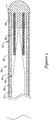
- Figure 1 is a plan view of an example medical device 10, for example a guidewire, disposed in a blood vessel 12.
- Guidewire 10 may include a distal section 14 that may be generally configured for use within the anatomy of a patient.
- Guidewire 10 may be used for intravascular procedures according to common practice and procedure.
- guidewire 10 may be used in conjunction with another medical device 16, which may take the form of a catheter, to treat and/or diagnose a medical condition.
- another medical device 16 which may take the form of a catheter, to treat and/or diagnose a medical condition.
- numerous other uses are known amongst clinicians for guidewires and other similarly configured medical devices.
- guidewire 10 may include a core wire 18 and a tubular member 24 disposed over at least a portion of core wire 18.
- core wire 18 may extend to the distal end of tubular member 24.
- tubular member 24 may extend distally beyond the distal end of core wire 18.
- a sheath or covering 22 may be disposed over portions or all of core wire 18 and/or tubular member 24 that may define a generally smooth outer surface for guidewire 10. In other embodiments, however, such a sheath or covering 22 may be absent from a portion of all of guidewire 10, such that tubular member 24 and/or core wire 18 may form the outer surface.
- a coil 46 may be disposed adjacent to core wire 18 and/or tubular member 24.
- the sheath or covering 22 is partially cut away to show a side view of core wire 18 and tubular member 24.
- a rounded or generally atraumatic distal tip 11 can be formed at the distal end of guidewire 10.
- Core wire 18 may extend to and/or into distal tip 11, or may end proximally thereof.
- tubular member 24 is attached to core wire 18.
- tubular member 24 and core wire 18 can be attached at the proximal end of tubular member 24, the distal end of tubular member 24, both, and/or at any suitable position therebetween.
- FIG. 10 depicts another example medical device 10' as a catheter having a catheter shaft 54.
- the proximal end of shaft 54 may include a proximal hub 56.
- Hub 56 may include a strain relief 60.
- the distal end of shaft 54 may include a distal tip region 58 which may take any number of forms.
- Catheter shaft 54 may include tubular member 24', which may be similar to other tubular members disclosed herein including tubular member 24.
- a plurality of slots 26' may be formed in tubular member 24'. Slots 26' may be similar to slots 26 (described below) or any other slots described herein.
- Tubular member 24' may extend along any portion or all of catheter shaft 54.
- Catheter 10' may also include any of the features described in U.S. Patent No. 7,001,369 .
- tubular member 24 includes a plurality of slots 26 formed therein that extend between the outer surface 30 and the inner surface 31 of tubular member 24.
- Slots 26 may be micromachined or otherwise created in tubular member 24, and may be configured to make tubular member 24 more flexible in bending. It is worth noting that, to the extent applicable, the methods for forming slots 26 can include, for example, any of the appropriate micromachining methods and other cutting methods disclosed in U.S. Pat. Publication Nos. US 2003/0069522 and US 2004 0181174 A2 , and/or U.S. Pat. Nos. 6,766,720 and 6,579,246 .
- These and other cutting methods may also include saw cutting (e.g., diamond grit embedded semiconductor dicing blade), etching (for example using the etching process described in U.S. Pat. No. 5,106,455 ), laser cutting, electron discharge machining, or the like. It should be noted that the methods for manufacturing guidewire 10 may include forming slots 26 in tubular member 24 using any of these or other manufacturing steps.
- slots 26 may be generally arranged to be perpendicular to the longitudinal axis of tubular member 24. This arrangement can, alternatively, be described as having slots 26 lying within a plane that is normal to the longitudinal axis of tubular member 24. In other embodiments, slots 26 may be formed at an angle relative to a plane that is normal to the longitudinal axis. In some embodiments, slots 26 may be formed part way through tubular member 24, while in other embodiments, slots 26 may extend all the way through tubular member 24. Any one or more of the individual slots 26 may extend only partially around the longitudinal axis of tubular member 24.
- slots 26 may extend in a helical arrangement about the longitudinal axis of tubular member 24. Slots 26 may be formed in groups of two, three, or more slots 26, which may be located at substantially the same location along the axis of tubular member 24, and may be substantially perpendicular to the longitudinal axis.
- the distribution and/or configuration of slots 24 can also include, to the extent applicable, any of those disclosed in U.S. Pat. Publication No. US 2004/0181174 .
- Slots 26 may be disposed in tubular member 24 with at least some of these design considerations in mind.
- Figure 3 shows a portion of tubular member 24, here it can be seen that slots 26 may have an oval or elliptical shape.
- slots 26 may also be formed in tubular member 24 in a manner such that slots 26 have a different geometry or shape at the outside surface 30 of tubular member 24 than at the inside surface 31 (best seen in Figure 3A ) of tubular member 24.
- slots 26 may have a first geometry or shape 28a along the outer surface 30 and a second geometry or shape 28b along the inner surface 31.
- first geometry 28a and second geometry 28b are different sizes of the same shape.
- first geometry 28a and second geometry 28b are geometrically similar - i.e., are different sizes of the same shape. This may be true even if the curves or arcs that formed the oval, ellipse, or other closed figure are different due to the different sizes of the objects.
- the intention is that the geometry of slots 26 is different between outer surface 30 and inner surface 31 in at least some tangible way including, for example, a change in size and/or a change in shape.
- This notation is not intended to mean that geometries 28a/28b are necessarily different geometric forms (e.g., circle versus square) even though these types of arrangements are contemplated.
- some embodiments of tubular members 24 include slots 26 that have a different shape altogether (e.g., circle versus square) along outer surface 30 than along inner surface 31.
- tubular member 24 includes a bevel or beveled region 27 where the first geometry 28a transitions to the second geometry 28b (see also Figures 3A-3B ).
- Bevel 27 may be disposed at essentially any suitable angle relative to outer surface 30.
- bevel 27 is disposed at a changing or variable angle.
- bevel 27 is a structural element of tubular member 24 where first geometry 28a changes to second geometry 28b.
- Forming slots 26 may include the use of a suitable cutting device that includes a blade 32.
- Blade 32 includes a cutting surface 34 that is designed to create the desired shape and/or configuration for slots 26.
- blade 32 may include a rounded or curved cutting surface 34 that can form the oval slots 26 in tubular member 24.
- the arced shape of cutting surface 34 may also be configured to form bevel 27.
- blade 32 may form slots 26 such that the width of slot 26 along inner surface 31 is smaller than the width of slot 26 along outer surface 30.
- This may provide tubular member 24 with a number of desirable features.
- some slot 26 geometries and/or configurations may provide better fatigue life versus stiffness, better axial stiffness versus bending stiffness ratios, better torsional versus bending stiffness ratios, etc. than other slot shapes and/or configurations.
- the geometry and/or configuration of slots 26 may be chosen to reduce machining and/or cutting time by reducing the number of features incorporated into tubular member 24 per unit length.
- slots 26 may be wider along outer surface 30, fewer slots 26 may be needed to produce a tubular member 24 having the desired properties (e.g., flexibility, torsional rigidity, etc.).
- blade 32 can form slots 26 so that they have a width along outer surface 30 that is has about one tenth or more of the length of the outer diameter of tubular member 24.
- the width of slots 26 along inner surface 31 may be about one tenth or less of the length of the outer diameter of tubular member 24.
- slots 26 may be oval.
- the depiction of slots 26 as being oval is not intended to be limiting as several other shapes are contemplated.
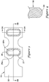
- Figure 5 illustrates a portion of tubular member 124 having slots 126 with a half-moon shape.
- the phrase "half-moon" shape may termed crescent shaped, semi-circular, semi-oval, etc. without departing from the scope of the invention.
- slots 126 have first geometry or shape 128a along the outer surface 130 of tubular member 124 and second geometry or shape 128b along the inner surface.
- Forming slots 126 may include the use of blade 132 having cutting surface 134.
- Cutting surface 134 may have a wedge-like shape or appearance.
- slots 126 can also vary.
- Figure 5 illustrates that slots 126 may be sequentially disposed along the longitudinally axis of tubular member 124.
- a series of slots e.g., a first slot 126 and a second slot 126'
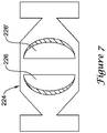
- Figure 7 illustrates another example tubular member 224 where subsequent slots (e.g., a first slots 226 and a second slot 226') are reverse such that the arched portions of slots 226/126' are on opposite sides.
- Tubular member 324 includes slots 326 that are diamond shaped. Slots 326 include bevel 327 that dictates that slots 326 have first geometry or shape 328a at the outer surface 330 of tubular member 324 and second geometry or shape 328b at the inner surface. Forming slots 326 may include the use of blade 332 having cutting surface 334. Cutting surface 334 may have a pointed shape, for example.
- guidewire 10 The materials that can be used for the various components of guidewire 10 may include those commonly associated with medical devices. It should be noted that any discussion related to a particular core wire (e.g., core wire 18), tubular member (e.g., tubular member 24), sheath (e.g., sheath 22), or any other component of a guidewire (e.g., guidewire 10) may also hold true for other core wires, tubular members, etc. disclosed herein.
- core wire 18 and/or tubular member 24 may be made from a metal, metal alloy, a metal-polymer composite, combinations thereof, and the like, or any other suitable material.
- suitable metals and metal alloys include stainless steel, such as 304V, 304L, and 316LV stainless steel; mild steel; nickel-titanium alloy such as linear-elastic and/or super-elastic nitinol; other nickel alloys such as nickel-chromium-molybdenum alloys (e.g., UNS: N06625 such as INCONEL® 625, UNS: N06022 such as HASTELLOY® C-22®, UNS: N10276 such as HASTELLOY® C276®, other HASTELLOY® alloys, and the like), nickel-copper alloys (e.g., UNS: N04400 such as MONEL® 400, NICKELVAC® 400, NICORROS® 400, and the like), nickel-cobalt-chromium-molybdenum alloys (e.g., UNS: R30035 such as MP35-N® and the like), nickel-molybdenum alloys (e.g.,
- Linear elastic and/or non-super-elastic nitinol may be distinguished from super elastic nitinol in that the linear elastic and/or non-super-elastic nitinol does not display a substantial "superelastic plateau” or “flag region” in its stress/strain curve like super elastic nitinol does.
- linear elastic and/or non-super-elastic nitinol as recoverable strain increases, the stress continues to increase in a substantially linear, or a somewhat, but not necessarily entirely linear relationship until plastic deformation begins or at least in a relationship that is more linear that the super elastic plateau and/or flag region that may be seen with super elastic nitinol.
- linear elastic and/or non-super-elastic nitinol may also be termed "substantially" linear elastic and/or non-super-elastic nitinol.
- linear elastic and/or non-super-elastic nitinol may also be distinguishable from super elastic nitinol in that linear elastic and/or non-super-elastic nitinol may accept up to about 2-5% strain while remaining substantially elastic (e.g., before plastically deforming) whereas super elastic nitinol may accept up to about 8% strain before plastically deforming. Both of these materials can be distinguished from other linear elastic materials such as stainless steel (that can also can be distinguished based on its composition), which may accept only about 0.2-0.44% strain before plastically deforming.
- the linear elastic and/or non-super-elastic nickel- titanium alloy is an alloy that does not show any martens ite/austenite phase changes that are detectable by DSC and DMTA analysis over a large temperature range.
- the mechanical bending properties of such material may therefore be generally inert to the effect of temperature over this very broad range of temperature.
- the mechanical bending properties of the linear elastic and/or non-super-elastic nickel- titanium alloy at ambient or room temperature are substantially the same as the mechanical properties at body temperature, for example, in that they do not display a super-elastic plateau and/or flag region.
- the linear elastic and/or non-super-elastic nickel-titanium alloy maintains its linear elastic and/or non-super-elastic characteristics and/or properties and has essentially no yield point.
- the linear elastic and/or non-super-elastic nickel- titanium alloy may be in the range of about 50 to about 60 weight percent nickel, with the remainder being essentially titanium. In some embodiments, the composition is in the range of about 54 to about 57 weight percent nickel.
- a suitable nickel-titanium alloy is FHP-NT alloy commercially available from Furukawa Techno Material Co. of Kanagawa, Japan. Some examples of nickel titanium alloys are disclosed in U.S. Patent Nos. 5,238,004 and 6,508,803 . Other suitable materials may include ULTANIUMTM (available from Neo-Metrics) and GUM METALTM (available from Toyota).
- a superelastic alloy for example a superelastic nitinol can be used to achieve desired properties.
- portions or all of core wire 18 and/or tubular member 24 may also be doped with, made of, or otherwise include a radiopaque material.
- Radiopaque materials are understood to be materials capable of producing a relatively bright image on a fluoroscopy screen or another imaging technique during a medical procedure. This relatively bright image aids the user of device 10 in determining its location.
- Some examples of radiopaque materials can include, but are not limited to, gold, platinum, palladium, tantalum, tungsten alloy, polymer material loaded with a radiopaque filler, and the like. Additionally, radiopaque marker bands and/or coils may be incorporated into the design of guidewire 10 to achieve the same result.
- a degree of MRI compatibility is imparted into device 10.
- core wire 18 and/or tubular member 24, or other portions of the medical device 10 may be made of a material that does not substantially distort the image and create substantial artifacts (artifacts are gaps in the image). Certain ferromagnetic materials, for example, may not be suitable because they may create artifacts in an MRI image.
- Core wire 18 and/or tubular member 24, or portions thereof may also be made from a material that the MRI machine can image.
- Some materials that exhibit these characteristics include, for example, tungsten, cobalt-chromium-molybdenum alloys (e.g., UNS: R30003 such as ELGILOY®, PHYNOX®, and the like), nickel-cobalt-chromium-molybdenum alloys (e.g., UNS: R30035 such as MP35-N® and the like), nitinol, and the like, and others.
- cobalt-chromium-molybdenum alloys e.g., UNS: R30003 such as ELGILOY®, PHYNOX®, and the like
- nickel-cobalt-chromium-molybdenum alloys e.g., UNS: R30035 such as MP35-N® and the like
- nitinol and the like, and others.
- the entire core wire 18 can be made of the same material along its length, or in some embodiments, can include portions or sections made of different materials.
- the material used to construct core wire 18 is chosen to impart varying flexibility and stiffness characteristics to different portions of core wire 18.
- the proximal region and the distal region of core wire 18 may be formed of different materials, for example materials having different moduli of elasticity, resulting in a difference in flexibility.
- the material used to construct the proximal region can be relatively stiff for pushability and torqueability, and the material used to construct the distal region can be relatively flexible by comparison for better lateral trackability and steerability.
- the proximal region can be formed of straightened 304v stainless steel wire or ribbon and the distal region can be formed of a straightened super elastic or linear elastic alloy, for example a nickel-titanium alloy wire or ribbon.
- the different portions can be connected using any suitable connecting techniques.
- the different portions of core wire 18 can be connected using welding (including laser welding), soldering, brazing, adhesive, or the like, or combinations thereof.
- some embodiments can include one or more mechanical connectors or connector assemblies to connect the different portions of core wire 18 that are made of different materials.
- the connector may include any structure generally suitable for connecting portions of a guidewire.
- a suitable structure includes a structure such as a hypotube or a coiled wire which has an inside diameter sized appropriately to receive and connect to the ends of the proximal portion and the distal portion.
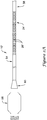
- Core wire 18 can have a solid cross-section, but in some embodiments, can have a hollow cross-section. In yet other embodiments, core wire 18 can include a combination of areas having solid cross-sections and hollow cross sections. Moreover, core wire 18, or portions thereof, can be made of rounded wire, flattened ribbon, or other such structures having various cross-sectional geometries. The cross- sectional geometries along the length of core wire 18 can also be constant or can vary. For example, Figure 2 depicts core wire 18 as having a round cross-sectional shape. It can be appreciated that other cross-sectional shapes or combinations of shapes may be utilized without departing from the scope of the invention. For example, the cross- sectional shape of core wire 18 may be oval, rectangular, square, polygonal, and the like, or any suitable shape.
- Sheath 22 may be made from a polymer or any other suitable material.
- suitable polymers may include polytetrafluoroethylene (PTFE), ethylene tetrafluoroethylene (ETFE), fluorinated ethylene propylene (FEP), polyoxymethylene (POM, for example, DELRIN® available from DuPont), polyether block ester, polyurethane, polypropylene (PP), polyvinylchloride (PVC), polyether-ester (for example, ARNITEL® available from DSM Engineering Plastics), ether or ester based copolymers (for example, butylene/poly(alkylene ether) phthalate and/or other polyester elastomers such as HYTREL® available from DuPont), polyamide (for example, DURETHAN® available from Bayer or CRISTAMID® available from Elf Atochem), elastomeric polyamides, block polyamide/ethers, polyether block amide (PEBA, for example available under the trade name PEBAX
- sheath 22 can be blended with a liquid crystal polymer (LCP).
- LCP liquid crystal polymer
- the mixture can contain up to about 6% LCP. This has been found to enhance torqueability.
- the exterior surface of the guidewire 10 may be sandblasted, beadblasted, sodium bicarbonate-blasted, electropolished, etc.
- a coating for example a lubricious, a hydrophilic, a protective, or other type of coating may be applied over portions or all of sheath 22, or in embodiments without a sheath 22 over portion of core wire 18 and/or tubular member, or other portions of device 10.
- sheath 22 may comprise a lubricious, hydrophilic, protective, or other type of coating.
- Hydrophobic coatings such as fluoropolymers provide a dry lubricity which improves guidewire handling and device exchanges.
- Lubricious coatings improve steerability and improve lesion crossing capability.
- Suitable lubricious polymers are well known in the art and may include silicone and the like, hydrophilic polymers such as high-density polyethylene (HDPE), polytetrafluoroethylene (PTFE), polyarylene oxides, polyvinylpyrolidones, polyvinylalcohols, hydroxy alkyl cellulosics, algins, saccharides, caprolactones, and the like, and mixtures and combinations thereof.
- HDPE high-density polyethylene
- PTFE polytetrafluoroethylene
- polyarylene oxides polyvinylpyrolidones
- polyvinylalcohols polyvinylalcohols
- hydroxy alkyl cellulosics algins
- Hydrophilic polymers may be blended among themselves or with formulated amounts of water insoluble compounds (including some polymers) to yield coatings with suitable lubricity, bonding, and solubility.
- Some other examples of such coatings and materials and methods used to create such coatings can be found in U.S. Patent Nos. 6,139,510 and 5,772,609 .
- the coating and/or sheath 22 may be formed, for example, by coating, extrusion, co-extrusion, interrupted layer co-extrusion (ILC), or fusing several segments end-to-end.
- the layer may have a uniform stiffness or a gradual reduction in stiffness from the proximal end to the distal end thereof. The gradual reduction in stiffness may be continuous as by ILC or may be stepped as by fusing together separate extruded tubular segments.
- the outer layer may be impregnated with a radiopaque filler material to facilitate radiographic visualization. Those skilled in the art will recognize that these materials can vary widely without deviating from the scope of the present invention.
- Figures 10-20 depict a variety of example tubular members and cuts formed in the example tubular members in order to illustrate some addition variations contemplated for the distribution of slots in a tubular member.
- similar reference numbers are used throughout these figures.
- several different tubular member may be formed or defined according to the forgoing description including several that may be utilized in any of the devices and/or guidewire disclosed herein.
- the description of these figures make use of the words "beam” and/or "beams”.
- the beams are the portion of the tubular member, often resembling a beam in appearance, that remains after cutting away a portion of the tubular member to form the slots.
- FIG 10 is a perspective view of an example tubular member 424, here it can be generally seen how slots 426 may be distributed along tubular member 424 as well as how beams 448 are located between slots 426.
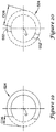
- Figure 11 when a cutting member or blade cuts into tubular member 424 to form slots, the blade slice through tubular member 424 at a particular angular position (e.g., for convenience sake assume the angular position is located at the right hand side or the 0° position of tubular member 424) to a position called the cut depth CD and defines a slot 426 (depicted in phantom as the portion of tubular member 424 removed by cutting).
- the beam height BH is the length of width of the beam in the radial direction.
- the beam height BH may be related to the cut depth CD and the outer diameter OD of tubular member 424. For example, in at least some cases the "deeper” the cut depth CD, the "shorter” the beam height BH.
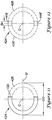
- tubular member 424 may be made at the same longitudinal position (e.g., from the opposite angular position (e.g., 180°) of tubular member 424 as shown in Figure 12 .
- a second slot 426' is formed.
- the second cut form a pair of slots 426/426', a pair of beams 448/448' are defined.
- additional pairs of slots and beams can be formed by making additional cuts.
- the cuts can be from the same position (e.g., from the 0° and the 180° positions of tubular member 424).
- the cuts can begin from a different angular position.
- the first cut made in tubular member 424 at a subsequent longitudinal position may be rotated a radial distance or angle A from where the first cut was made at the first longitudinal position.
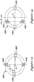
- Angle A could be any suitable angle such as, for example, about 60-120° or about 85° as shown in Figure 13 .
- Another cut from the opposite side of tubular member 424 defines a second pair of beams 450/450'. At other longitudinal positions, cuts can be rotated to the same extent or to different extents.
- all the beam pairs 448/448' and/or 450/450' all have centers that align with the tube centerline C (i.e., a line drawn between the middle of opposing pairs of beams goes through the tube centerline C). While this can be desirable in some embodiments, other arrangements are contemplated that include beam centers that are offset from the tube centerline C to create structures with lower bending stiffness.
- Figure 14 depicts tubular member 424' where beam pairs 448/448' and beam pairs 450/450' are rotated 90° relative to one another. Beams 448/448' are aligned with the tube centerline C. However, beams 450/450' are offset a distance D from the tube centerline C.
- Arrangements like this may result in a tubular member that is anisotrophic (i.e., soft in bending in one plane relative to other planes).
- Other arrangements are contemplated where both beams 448/448' and beams 450/450' are offset from the tube centerline C. The amount of offset may or may not be the same.
- the beam pairs may or may not be rotated around the circumference of tubular member 424' at any suitable angle. Embodiments where the offsets are the same and the angle is fixed may result in a tubular member that is isotrophic.
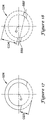
- FIG. 15 the cross-section of another example tubular member 524 is shown that can be used in any of the device described herein.
- the structure of tubular member 524 includes a slot/beam arrangement wherein the amount or distance of the beam offset varies as a function of the angular position from which the cut defining the slot/beam originates from.
- CD1 is the first cut in a pair of cuts that creates a pair of beams.
- CD2 is the second cut in a pair of cuts that creates a pair of beams.
- the MAXOFFSET is the maximum desired beam centerline offset, which can be fixed as any suitable distance.
- the ANGULARPOSITION is the angle from which the blade approaches the tube centerline C to make a given cut.
- the beam centerline for this pair of beams 550/550' would be 0.0872* MAXOFFSET units from the tube centerline C, toward the 265° position.
- the next cut would come from 85° (position of last cut) + 85° (helix angle) or 170°.
- the next cut would come from 170° +180° or 350°.
- the beam centerline for this pair of beams 552/552' would be shifted .9848* MAXOFFSET units from the tube centerline, toward the 170° direction.
- the beam-tube centerline offset for beam pairs at other angles will be distributed via the Cosine function between 0 and MAXOFFSET units. It can be appreciated that a similar strategy can be utilized using different functions (e.g., Sine, Tangent, etc.)
Claims (9)
- Dispositif médical (10 ; 10'), comprenant :une tige allongée (54) ayant une région proximale et une région distale ; etun élément tubulaire (24 ; 24' ; 124 ; 224 ; 324 ; 424 ; 424' ; 524) couplé à la région distale de la tige (54), l'élément tubulaire (24 ; 24' ; 124 ; 224 ; 324 ; 424 ; 424' ; 524) ayant une surface externe (30 ; 130 ; 330) et une surface interne (31) ;où l'élément tubulaire (24 ; 24' ; 124 ; 224 ; 324 ; 424 ; 424' ; 524) a une pluralité de fentes (26 ; 26' ; 126, 126' ; 226, 226' ; 326 ; 426, 426') définies dans celui-ci ; où les fentes (26 ; 26' ; 126, 126' ; 226, 226' ; 326 ; 426, 426') ont une première géométrie (28a ; 128a ; 328a) au niveau de la surface externe (30 ; 130 ; 330) et une seconde géométrie (28b ; 128b ; 328b) au niveau de la surface interne (31), la première géométrie (28a ; 128a ; 328a) étant différente de la seconde géométrie (28b ; 128b ; 328b) ; et où un biseau (27 ; 127 ; 327) est formé dans l'élément tubulaire (24 ; 24' ; 124 ; 224 ; 324 ; 424 ; 424' ; 524), le biseau (27 ; 127 ; 327) opérant une transition de la première géométrie (28a ; 128a ; 328a) à la seconde géométrie (28b ; 128b ; 328b) caractérisé en ce que le biseau (27 ; 127 ; 327) est disposé sous un angle variable.
- Dispositif médical (10 ; 10') selon la revendication 1, où la première géométrie (28a ; 128a ; 328a) et la seconde géométrie (28b ; 128b ; 328b) sont des formes géométriquement similaires de tailles différentes.
- Dispositif médical (10 ; 10') selon la revendication 1 ou 2, où la première géométrie (28a ; 128a ; 328a) inclut une forme choisie dans le groupe consistant en ovale, elliptique, demi-cercle, demi-ovale, demi-lune et losange.
- Dispositif médical (10 ; 10') selon l'une quelconque des revendications 1-3, où les fentes (26 ; 26' ; 126, 126'; 226, 226' ; 326 ; 426, 426') sont disposées successivement en rangées longitudinales le long de la surface externe.
- Dispositif médical (10 ; 10') selon la revendication 4, où au moins certaines des fentes (26 ; 26' ; 126, 126'; 226, 226' ; 326 ; 426, 426') sont inversées par rapport à une fente (26 ; 26' ; 126, 126' ; 226, 226' ; 326 ; 426, 426') immédiatement précédente.
- Dispositif médical (10 ; 10') selon l'une quelconque des revendications 1-5, où l'élément tubulaire (24 ; 24' ; 124 ; 224 ; 324 ; 424 ; 424' ; 524) inclut une première paire de traverses (448, 448' ; 450, 450'; 548, 548' ; 550, 550' ; 552, 552').
- Dispositif médical (10 ; 10') selon l'une quelconque des revendications 1-6, où l'élément tubulaire (24 ; 24' ; 124 ; 224 ; 324 ; 424 ; 424'; 524) inclut un axe de tube (C) et où la première paire de traverses (448, 448' ; 450, 450' ; 548, 548' ; 550, 550' ; 552, 552) sont décalées d'une distance (D) par rapport à l'axe de tube (C).
- Dispositif médical (10 ; 10') selon l'une quelconque des revendications 1-7, où l'élément tubulaire (24 ; 24' ; 124 ; 224 ; 324 ; 424 ; 424' ; 524) inclut un alliage nickel-titane.
- Procédé de fabrication du dispositif médical (10 ; 10') selon l'une quelconque des revendications 1-8, le procédé comprenant les étapes de :fournir un élément tubulaire (24 ; 24' ; 124 ; 224 ; 324 ; 424 ; 424' ; 524) ; l'élément tubulaire (24 ; 24' ; 124 ; 224 ; 324 ; 424 ; 424' ; 524) ayant une surface externe (30 ; 130 ; 330) et une surface interne (31) ;fournir une lame de coupe (32 ; 132 ; 332) ayant une surface de coupe (34 ; 134 ; 334) ; etdécouper une pluralité de fentes (26 ; 26'; 126, 126'; 226, 226' ; 326 ; 426, 426) dans l'élément tubulaire (24 ; 24' ; 124 ; 224 ; 324 ; 424 ; 424' ; 524) avec la lame de coupe (32 ; 132 ; 332).
Priority Applications (1)
| Application Number | Priority Date | Filing Date | Title |
|---|---|---|---|
| EP19179157.3A EP3572118B1 (fr) | 2008-01-03 | 2008-12-22 | Éléments tubulaires de découpe pour un dispositif médical et leurs procédés de fabrication et d'utilisation |
Applications Claiming Priority (2)
| Application Number | Priority Date | Filing Date | Title |
|---|---|---|---|
| US11/969,212 US8460213B2 (en) | 2008-01-03 | 2008-01-03 | Cut tubular members for a medical device and methods for making and using the same |
| PCT/US2008/088058 WO2009088751A1 (fr) | 2008-01-03 | 2008-12-22 | Eléments tubulaires de découpe pour un dispositif médical et procédés de fabrication et d'utilisation de ceux-ci |
Related Child Applications (1)
| Application Number | Title | Priority Date | Filing Date |
|---|---|---|---|
| EP19179157.3A Division EP3572118B1 (fr) | 2008-01-03 | 2008-12-22 | Éléments tubulaires de découpe pour un dispositif médical et leurs procédés de fabrication et d'utilisation |
Publications (2)
| Publication Number | Publication Date |
|---|---|
| EP2249912A1 EP2249912A1 (fr) | 2010-11-17 |
| EP2249912B1 true EP2249912B1 (fr) | 2019-06-12 |
Family
ID=40386202
Family Applications (2)
| Application Number | Title | Priority Date | Filing Date |
|---|---|---|---|
| EP19179157.3A Active EP3572118B1 (fr) | 2008-01-03 | 2008-12-22 | Éléments tubulaires de découpe pour un dispositif médical et leurs procédés de fabrication et d'utilisation |
| EP08870005.9A Active EP2249912B1 (fr) | 2008-01-03 | 2008-12-22 | Eléments tubulaires de découpe pour un dispositif médical et procédés de fabrication et d'utilisation de ceux-ci |
Family Applications Before (1)
| Application Number | Title | Priority Date | Filing Date |
|---|---|---|---|
| EP19179157.3A Active EP3572118B1 (fr) | 2008-01-03 | 2008-12-22 | Éléments tubulaires de découpe pour un dispositif médical et leurs procédés de fabrication et d'utilisation |
Country Status (4)
| Country | Link |
|---|---|
| US (2) | US8460213B2 (fr) |
| EP (2) | EP3572118B1 (fr) |
| JP (1) | JP5827009B2 (fr) |
| WO (1) | WO2009088751A1 (fr) |
Families Citing this family (33)
| Publication number | Priority date | Publication date | Assignee | Title |
|---|---|---|---|---|
| US8460213B2 (en) * | 2008-01-03 | 2013-06-11 | Boston Scientific Scimed, Inc. | Cut tubular members for a medical device and methods for making and using the same |
| US10363389B2 (en) | 2009-04-03 | 2019-07-30 | Scientia Vascular, Llc | Micro-fabricated guidewire devices having varying diameters |
| US11406791B2 (en) | 2009-04-03 | 2022-08-09 | Scientia Vascular, Inc. | Micro-fabricated guidewire devices having varying diameters |
| CN105459189B (zh) | 2008-12-08 | 2018-05-08 | 血管科学有限公司 | 沿备料的长度形成多个切口以形成产品的系统和方法 |
| US9950137B2 (en) | 2009-04-03 | 2018-04-24 | Scientia Vascular, Llc | Micro-fabricated guidewire devices formed with hybrid materials |
| US8551021B2 (en) | 2010-03-31 | 2013-10-08 | Boston Scientific Scimed, Inc. | Guidewire with an improved flexural rigidity profile |
| SE535022C2 (sv) | 2010-06-30 | 2012-03-20 | St Jude Medical Systems Ab | Sensorguidewire innefattande en sensorkapsel med multipla hål |
| EP2621335B1 (fr) | 2010-09-29 | 2015-11-18 | St. Jude Medical Coordination Center BVBA | Fil-guide à capteur |
| US20120095566A1 (en) * | 2010-10-18 | 2012-04-19 | Boston Scientific Scimed, Inc. | Flexible ureteral stent |
| EP2670470B1 (fr) | 2011-02-04 | 2019-04-24 | Boston Scientific Scimed, Inc. | Fils guides |
| US9072874B2 (en) | 2011-05-13 | 2015-07-07 | Boston Scientific Scimed, Inc. | Medical devices with a heat transfer region and a heat sink region and methods for manufacturing medical devices |
| ES2836119T3 (es) * | 2011-10-21 | 2021-06-24 | Viking Systems Inc | Endoscopio estereoscópico electrónico orientable |
| EP2826516B1 (fr) * | 2012-03-16 | 2019-04-17 | Terumo Kabushiki Kaisha | Fil-guide |
| US10226185B2 (en) | 2012-05-03 | 2019-03-12 | St. Jude Medical Coordination Center Bvba | Tube and sensor guide wire comprising tube |
| KR101466705B1 (ko) * | 2013-04-16 | 2014-12-01 | 한국과학기술연구원 | 비등방성 패턴을 갖는 튜브 연속체 로봇 및 튜브 제조 방법 |
| EP3060105A2 (fr) | 2013-10-25 | 2016-08-31 | St. Jude Medical Coordination Center BVBA | Dispositif de fil guide de capteur et système comprenant un dispositif de fil guide de capteur |
| EP3065805A1 (fr) | 2013-11-04 | 2016-09-14 | Nitiloop Ltd. | Agencement de tubes pour microcathéter |
| EP3137148B1 (fr) | 2014-05-02 | 2021-12-22 | Intellimedical Technologies Pty Ltd | Dispositifs orientables allongés à introduire dans le corps d'un sujet |
| USD743007S1 (en) * | 2014-12-01 | 2015-11-10 | Asahi Intecc Co., Ltd. | Slitted pipe |
| WO2016138226A1 (fr) | 2015-02-26 | 2016-09-01 | St. Jude Medical Coordination Center Bvba | Capteur de pression et fil-guide avec tube à humidification automatique |
| US10792473B2 (en) | 2016-03-16 | 2020-10-06 | St. Jude Medical Coordination Center Bvba | Core wire having a flattened portion to provide preferential bending |
| US10252024B2 (en) * | 2016-04-05 | 2019-04-09 | Stryker Corporation | Medical devices and methods of manufacturing same |
| US11052228B2 (en) | 2016-07-18 | 2021-07-06 | Scientia Vascular, Llc | Guidewire devices having shapeable tips and bypass cuts |
| US11207502B2 (en) | 2016-07-18 | 2021-12-28 | Scientia Vascular, Llc | Guidewire devices having shapeable tips and bypass cuts |
| US10821268B2 (en) | 2016-09-14 | 2020-11-03 | Scientia Vascular, Llc | Integrated coil vascular devices |
| US11452541B2 (en) | 2016-12-22 | 2022-09-27 | Scientia Vascular, Inc. | Intravascular device having a selectively deflectable tip |
| WO2018129455A1 (fr) | 2017-01-09 | 2018-07-12 | Boston Scientific Scimed, Inc. | Fil-guide à sensation tactile |
| JP2020521552A (ja) | 2017-05-26 | 2020-07-27 | サイエンティア・バスキュラー・エルエルシー | 非らせんカット配列を有する微細加工医療デバイス |
| US11202888B2 (en) | 2017-12-03 | 2021-12-21 | Cook Medical Technologies Llc | MRI compatible interventional wireguide |
| US11305095B2 (en) | 2018-02-22 | 2022-04-19 | Scientia Vascular, Llc | Microfabricated catheter having an intermediate preferred bending section |
| US20200345975A1 (en) * | 2019-05-02 | 2020-11-05 | Scientia Vascular, Llc | Intravascular device with enhanced one-beam cut pattern |
| CA3132792A1 (fr) | 2019-05-15 | 2020-11-19 | Boston Scientific Scimed, Inc. | Dispositif medical a courbure asymetrique |
| CN113698085B (zh) * | 2021-07-05 | 2022-05-20 | 维达力实业(赤壁)有限公司 | 避空槽加工方法以及3d基板产品 |
Family Cites Families (116)
| Publication number | Priority date | Publication date | Assignee | Title |
|---|---|---|---|---|
| US3241758A (en) * | 1964-06-24 | 1966-03-22 | Foxboro Co | Fluid logic pulse frequency rate system |
| US4547193A (en) | 1984-04-05 | 1985-10-15 | Angiomedics Incorporated | Catheter having embedded multi-apertured film |
| US4580551A (en) | 1984-11-02 | 1986-04-08 | Warner-Lambert Technologies, Inc. | Flexible plastic tube for endoscopes and the like |
| US4795439A (en) | 1986-06-06 | 1989-01-03 | Edward Weck Incorporated | Spiral multi-lumen catheter |
| US4753238A (en) | 1987-01-06 | 1988-06-28 | Advanced Cardiovascular Systems, Inc. | Proximal manifold and adapter |
| US4998923A (en) | 1988-08-11 | 1991-03-12 | Advanced Cardiovascular Systems, Inc. | Steerable dilatation catheter |
| US5507751A (en) | 1988-11-09 | 1996-04-16 | Cook Pacemaker Corporation | Locally flexible dilator sheath |
| US5095915A (en) | 1990-03-19 | 1992-03-17 | Target Therapeutics | Guidewire with flexible distal tip |
| US5238004A (en) | 1990-04-10 | 1993-08-24 | Boston Scientific Corporation | High elongation linear elastic guidewire |
| US5106455A (en) | 1991-01-28 | 1992-04-21 | Sarcos Group | Method and apparatus for fabrication of micro-structures using non-planar, exposure beam lithography |
| US5315996A (en) | 1991-02-15 | 1994-05-31 | Lundquist Ingemar H | Torquable catheter and method |
| US5228441A (en) | 1991-02-15 | 1993-07-20 | Lundquist Ingemar H | Torquable catheter and method |
| AU660444B2 (en) | 1991-02-15 | 1995-06-29 | Ingemar H. Lundquist | Torquable catheter and method |
| US5329923A (en) | 1991-02-15 | 1994-07-19 | Lundquist Ingemar H | Torquable catheter |
| US5741429A (en) | 1991-09-05 | 1998-04-21 | Cardia Catheter Company | Flexible tubular device for use in medical applications |
| CA2117088A1 (fr) | 1991-09-05 | 1993-03-18 | David R. Holmes | Dispositif tubulaire flexible presentant des applications medicales |
| US5328472A (en) | 1992-07-27 | 1994-07-12 | Medtronic, Inc. | Catheter with flexible side port entry |
| US5437288A (en) | 1992-09-04 | 1995-08-01 | Mayo Foundation For Medical Education And Research | Flexible catheter guidewire |
| US5334145A (en) | 1992-09-16 | 1994-08-02 | Lundquist Ingemar H | Torquable catheter |
| US5372144A (en) | 1992-12-01 | 1994-12-13 | Scimed Life Systems, Inc. | Navigability improved guidewire construction and method of using same |
| JP3345147B2 (ja) | 1993-01-26 | 2002-11-18 | テルモ株式会社 | 血管拡張器具およびカテーテル |
| EP0608853B1 (fr) | 1993-01-26 | 2003-04-02 | Terumo Kabushiki Kaisha | Dispositif de dilatation vasculaire et cathéter |
| US6576008B2 (en) | 1993-02-19 | 2003-06-10 | Scimed Life Systems, Inc. | Methods and device for inserting and withdrawing a two piece stent across a constricting anatomic structure |
| US5772609A (en) | 1993-05-11 | 1998-06-30 | Target Therapeutics, Inc. | Guidewire with variable flexibility due to polymeric coatings |
| FR2706883B1 (fr) * | 1993-06-23 | 1995-10-20 | Degremont | |
| US5989280A (en) | 1993-10-22 | 1999-11-23 | Scimed Lifesystems, Inc | Stent delivery apparatus and method |
| AU685575B2 (en) | 1994-03-10 | 1998-01-22 | Schneider (Usa) Inc. | Catheter having shaft of varying stiffness |
| US5902290A (en) | 1994-03-14 | 1999-05-11 | Advanced Cardiovascular Systems, Inc. | Catheter providing intraluminal access |
| US6139510A (en) | 1994-05-11 | 2000-10-31 | Target Therapeutics Inc. | Super elastic alloy guidewire |
| US5569197A (en) | 1994-12-21 | 1996-10-29 | Schneider (Usa) Inc | Drug delivery guidewire |
| US5797856A (en) | 1995-01-05 | 1998-08-25 | Cardiometrics, Inc. | Intravascular guide wire and method |
| US5788707A (en) | 1995-06-07 | 1998-08-04 | Scimed Life Systems, Inc. | Pull back sleeve system with compression resistant inner shaft |
| US6287315B1 (en) | 1995-10-30 | 2001-09-11 | World Medical Manufacturing Corporation | Apparatus for delivering an endoluminal prosthesis |
| EP0778039A1 (fr) | 1995-12-07 | 1997-06-11 | Sarcos, Inc. | Fil de guidage pour cathéter |
| US20030069522A1 (en) | 1995-12-07 | 2003-04-10 | Jacobsen Stephen J. | Slotted medical device |
| US6428489B1 (en) | 1995-12-07 | 2002-08-06 | Precision Vascular Systems, Inc. | Guidewire system |
| US5833632A (en) | 1995-12-07 | 1998-11-10 | Sarcos, Inc. | Hollow guide wire apparatus catheters |
| US6004279A (en) | 1996-01-16 | 1999-12-21 | Boston Scientific Corporation | Medical guidewire |
| US5695506A (en) | 1996-02-06 | 1997-12-09 | Devices For Vascular Intervention | Catheter device with a flexible housing |
| US6533805B1 (en) | 1996-04-01 | 2003-03-18 | General Surgical Innovations, Inc. | Prosthesis and method for deployment within a body lumen |
| US6629981B2 (en) | 2000-07-06 | 2003-10-07 | Endocare, Inc. | Stent delivery system |
| US6017319A (en) | 1996-05-24 | 2000-01-25 | Precision Vascular Systems, Inc. | Hybrid tubular guide wire for catheters |
| WO1997044086A1 (fr) | 1996-05-24 | 1997-11-27 | Sarcos, Inc. | Procede et appareil fil de guidage/catheter a ballon flexible |
| US6440088B1 (en) | 1996-05-24 | 2002-08-27 | Precision Vascular Systems, Inc. | Hybrid catheter guide wire apparatus and method |
| US6077295A (en) | 1996-07-15 | 2000-06-20 | Advanced Cardiovascular Systems, Inc. | Self-expanding stent delivery system |
| US6123712A (en) | 1996-08-23 | 2000-09-26 | Scimed Life Systems, Inc. | Balloon catheter with stent securement means |
| CA2263492C (fr) | 1996-08-23 | 2006-10-17 | Scimed Life Systems, Inc. | Systeme d'acheminement d'un stent, dote d'un appareil d'arrimage dudit stent |
| US6391032B2 (en) | 1996-08-23 | 2002-05-21 | Scimed Life Systems, Inc. | Stent delivery system having stent securement means |
| US6077273A (en) | 1996-08-23 | 2000-06-20 | Scimed Life Systems, Inc. | Catheter support for stent delivery |
| US6007543A (en) | 1996-08-23 | 1999-12-28 | Scimed Life Systems, Inc. | Stent delivery system with stent securement means |
| US6014919A (en) | 1996-09-16 | 2000-01-18 | Precision Vascular Systems, Inc. | Method and apparatus for forming cuts in catheters, guidewires, and the like |
| US5772669A (en) | 1996-09-27 | 1998-06-30 | Scimed Life Systems, Inc. | Stent deployment catheter with retractable sheath |
| US6001068A (en) | 1996-10-22 | 1999-12-14 | Terumo Kabushiki Kaisha | Guide wire having tubular connector with helical slits |
| DE19721703A1 (de) | 1997-05-23 | 1998-11-26 | Angiomed Ag | Kathetersystem mit hoher Knickfestigkeit |
| US6273876B1 (en) * | 1997-12-05 | 2001-08-14 | Intratherapeutics, Inc. | Catheter segments having circumferential supports with axial projection |
| US6245095B1 (en) | 1998-03-24 | 2001-06-12 | Innercool Therapies, Inc. | Method and apparatus for location and temperature specific drug action such as thrombolysis |
| KR19990072499A (ko) | 1998-02-19 | 1999-09-27 | 리페르트 존 | 유연성이높은부위를가지는카테테르안내와이어장치 |
| US6174327B1 (en) | 1998-02-27 | 2001-01-16 | Scimed Life Systems, Inc. | Stent deployment apparatus and method |
| EP0941713B1 (fr) | 1998-03-04 | 2004-11-03 | Schneider (Europe) GmbH | Dispositif pour introduire une endoprothèse dans le tube d' un cathéter |
| DE29803816U1 (de) | 1998-03-04 | 1998-04-23 | Hsu Hsin Hsuan | Notenständer |
| EP1067882A1 (fr) | 1998-03-31 | 2001-01-17 | Salviac Limited | Catheter de mise en place |
| IE980241A1 (en) | 1998-04-02 | 1999-10-20 | Salviac Ltd | Delivery catheter with split sheath |
| US6004310A (en) | 1998-06-17 | 1999-12-21 | Target Therapeutics, Inc. | Multilumen catheter shaft with reinforcement |
| US6048339A (en) | 1998-06-29 | 2000-04-11 | Endius Incorporated | Flexible surgical instruments with suction |
| US6093194A (en) | 1998-09-14 | 2000-07-25 | Endocare, Inc. | Insertion device for stents and methods for use |
| US6106455A (en) | 1998-10-21 | 2000-08-22 | Kan; William C. | Radioactive seed vacuum pickup probe |
| WO2000027462A1 (fr) | 1998-11-06 | 2000-05-18 | The Furukawa Electric Co., Ltd. | FIL-GUIDE MEDICAL DU TYPE NiTi ET PROCEDE DE PRODUCTION |
| US6102932A (en) | 1998-12-15 | 2000-08-15 | Micrus Corporation | Intravascular device push wire delivery system |
| US6254609B1 (en) | 1999-01-11 | 2001-07-03 | Scimed Life Systems, Inc. | Self-expanding stent delivery system with two sheaths |
| EP1092449A1 (fr) | 1999-04-30 | 2001-04-18 | Usaminanotechnology, Inc. | Catheter a fil-guide |
| US6241758B1 (en) | 1999-05-28 | 2001-06-05 | Advanced Cardiovascular Systems, Inc. | Self-expanding stent delivery system and method of use |
| US6168617B1 (en) | 1999-06-14 | 2001-01-02 | Scimed Life Systems, Inc. | Stent delivery system |
| US6398802B1 (en) | 1999-06-21 | 2002-06-04 | Scimed Life Systems, Inc. | Low profile delivery system for stent and graft deployment |
| US6287291B1 (en) | 1999-11-09 | 2001-09-11 | Advanced Cardiovascular Systems, Inc. | Protective sheath for catheters |
| US6702802B1 (en) | 1999-11-10 | 2004-03-09 | Endovascular Technologies, Inc. | Catheters with improved transition |
| AU2045401A (en) * | 1999-11-24 | 2001-06-04 | Radius International Limited Partnership | Blood vessel catheter |
| US6579246B2 (en) | 1999-12-22 | 2003-06-17 | Sarcos, Lc | Coronary guidewire system |
| US6602280B2 (en) | 2000-02-02 | 2003-08-05 | Trivascular, Inc. | Delivery system and method for expandable intracorporeal device |
| EP1255579A1 (fr) | 2000-02-15 | 2002-11-13 | Eva Corporation | Ensemble catheter de pose et technique de fixation d'un dispositif de fixation d'un element chirurgical sur un vaisseau |
| US6773446B1 (en) | 2000-08-02 | 2004-08-10 | Cordis Corporation | Delivery apparatus for a self-expanding stent |
| US6461321B1 (en) * | 2000-08-30 | 2002-10-08 | Radius International Limited Partnership | Hemodialysis catheter |
| US6562064B1 (en) | 2000-10-27 | 2003-05-13 | Vascular Architects, Inc. | Placement catheter assembly |
| US6428566B1 (en) | 2000-10-31 | 2002-08-06 | Advanced Cardiovascular Systems, Inc. | Flexible hoop and link sheath for a stent delivery system |
| US6436090B1 (en) | 2000-12-21 | 2002-08-20 | Advanced Cardiovascular Systems, Inc. | Multi lumen catheter shaft |
| US6592568B2 (en) | 2001-01-11 | 2003-07-15 | Scimed Life Systems, Inc. | Balloon assembly for stent delivery catheter |
| US6623491B2 (en) | 2001-01-18 | 2003-09-23 | Ev3 Peripheral, Inc. | Stent delivery system with spacer member |
| US6699274B2 (en) | 2001-01-22 | 2004-03-02 | Scimed Life Systems, Inc. | Stent delivery system and method of manufacturing same |
| US6743210B2 (en) | 2001-02-15 | 2004-06-01 | Scimed Life Systems, Inc. | Stent delivery catheter positioning device |
| US6592549B2 (en) | 2001-03-14 | 2003-07-15 | Scimed Life Systems, Inc. | Rapid exchange stent delivery system and associated components |
| US6660031B2 (en) | 2001-04-11 | 2003-12-09 | Scimed Life Systems, Inc. | Multi-length delivery system |
| BR0210563A (pt) | 2001-06-20 | 2004-05-25 | Microventio Inc | Dispositivo médico inserìvel no corpo de um paciente humano ou veterinário, e, método de fabricação de um dispositivo médico revestido |
| CA2450251C (fr) | 2001-07-05 | 2008-10-21 | Precision Vascular Systems, Inc. | Dispositif medical a pointe souple pouvant etre soumis a un couple et son procede d'utilisation |
| US6726714B2 (en) | 2001-08-09 | 2004-04-27 | Scimed Life Systems, Inc. | Stent delivery system |
| US6918882B2 (en) | 2001-10-05 | 2005-07-19 | Scimed Life Systems, Inc. | Guidewire with stiffness blending connection |
| US6652508B2 (en) | 2001-11-09 | 2003-11-25 | Scimed Life Systems, Inc. | Intravascular microcatheter having hypotube proximal shaft with transition |
| US7294124B2 (en) | 2001-12-28 | 2007-11-13 | Boston Scientific Scimed, Inc. | Hypotube with improved strain relief |
| US7914467B2 (en) * | 2002-07-25 | 2011-03-29 | Boston Scientific Scimed, Inc. | Tubular member having tapered transition for use in a medical device |
| US7878984B2 (en) * | 2002-07-25 | 2011-02-01 | Boston Scientific Scimed, Inc. | Medical device for navigation through anatomy and method of making same |
| US20040167441A1 (en) | 2003-02-26 | 2004-08-26 | Reynolds Brian R. | Composite medical device |
| US20040167437A1 (en) | 2003-02-26 | 2004-08-26 | Sharrow James S. | Articulating intracorporal medical device |
| US7276062B2 (en) | 2003-03-12 | 2007-10-02 | Biosence Webster, Inc. | Deflectable catheter with hinge |
| US7001369B2 (en) | 2003-03-27 | 2006-02-21 | Scimed Life Systems, Inc. | Medical device |
| US6899202B1 (en) | 2003-08-13 | 2005-05-31 | Mcintyre John | Brake assembly for a bicycle |
| US7785273B2 (en) | 2003-09-22 | 2010-08-31 | Boston Scientific Scimed, Inc. | Guidewire with reinforcing member |
| US7637903B2 (en) * | 2004-02-09 | 2009-12-29 | Cryocor, Inc. | Catheter articulation segment with alternating cuts |
| US7744619B2 (en) | 2004-02-24 | 2010-06-29 | Boston Scientific Scimed, Inc. | Rotatable catheter assembly |
| US20050234499A1 (en) | 2004-04-19 | 2005-10-20 | Scimed Life Systems, Inc. | Multi-lumen balloon catheter including manifold |
| US20070083132A1 (en) | 2005-10-11 | 2007-04-12 | Sharrow James S | Medical device coil |
| US8292827B2 (en) | 2005-12-12 | 2012-10-23 | Boston Scientific Scimed, Inc. | Micromachined medical devices |
| US8419658B2 (en) * | 2006-09-06 | 2013-04-16 | Boston Scientific Scimed, Inc. | Medical device including structure for crossing an occlusion in a vessel |
| US8556914B2 (en) * | 2006-12-15 | 2013-10-15 | Boston Scientific Scimed, Inc. | Medical device including structure for crossing an occlusion in a vessel |
| US8821477B2 (en) * | 2007-08-06 | 2014-09-02 | Boston Scientific Scimed, Inc. | Alternative micromachined structures |
| US8460213B2 (en) * | 2008-01-03 | 2013-06-11 | Boston Scientific Scimed, Inc. | Cut tubular members for a medical device and methods for making and using the same |
| US8376961B2 (en) * | 2008-04-07 | 2013-02-19 | Boston Scientific Scimed, Inc. | Micromachined composite guidewire structure with anisotropic bending properties |
| US8551021B2 (en) * | 2010-03-31 | 2013-10-08 | Boston Scientific Scimed, Inc. | Guidewire with an improved flexural rigidity profile |
| US8585643B2 (en) * | 2011-03-07 | 2013-11-19 | Stryker Corporation | Balloon catheter and method of manufacture |
-
2008
- 2008-01-03 US US11/969,212 patent/US8460213B2/en active Active
- 2008-12-22 EP EP19179157.3A patent/EP3572118B1/fr active Active
- 2008-12-22 EP EP08870005.9A patent/EP2249912B1/fr active Active
- 2008-12-22 WO PCT/US2008/088058 patent/WO2009088751A1/fr active Application Filing
- 2008-12-22 JP JP2010541489A patent/JP5827009B2/ja not_active Expired - Fee Related
-
2013
- 2013-06-11 US US13/915,449 patent/US9227037B2/en active Active
Non-Patent Citations (1)
| Title |
|---|
| None * |
Also Published As
| Publication number | Publication date |
|---|---|
| US20130267913A1 (en) | 2013-10-10 |
| EP2249912A1 (fr) | 2010-11-17 |
| JP2011508649A (ja) | 2011-03-17 |
| US8460213B2 (en) | 2013-06-11 |
| US20090177185A1 (en) | 2009-07-09 |
| EP3572118B1 (fr) | 2022-03-02 |
| WO2009088751A1 (fr) | 2009-07-16 |
| EP3572118A1 (fr) | 2019-11-27 |
| JP5827009B2 (ja) | 2015-12-02 |
| US9227037B2 (en) | 2016-01-05 |
Similar Documents
| Publication | Publication Date | Title |
|---|---|---|
| EP2249912B1 (fr) | Eléments tubulaires de découpe pour un dispositif médical et procédés de fabrication et d'utilisation de ceux-ci | |
| US8376961B2 (en) | Micromachined composite guidewire structure with anisotropic bending properties | |
| US9808595B2 (en) | Microfabricated catheter with improved bonding structure | |
| US8535243B2 (en) | Medical devices and tapered tubular members for use in medical devices | |
| US8795254B2 (en) | Medical devices with a slotted tubular member having improved stress distribution | |
| US8137293B2 (en) | Guidewires including a porous nickel-titanium alloy | |
| US8551020B2 (en) | Crossing guidewire | |
| US8795202B2 (en) | Guidewires and methods for making and using the same | |
| US7841994B2 (en) | Medical device for crossing an occlusion in a vessel | |
| US20090118704A1 (en) | Interconnected ribbon coils, medical devices including an interconnected ribbon coil, and methods for manufacturing an interconnected ribbon coil | |
| US20080262474A1 (en) | Medical device | |
| US20120209176A1 (en) | Balloon catheter | |
| WO2008076931A2 (fr) | Dispositif médical incluant une structure destinée à franchir une occlusion dans un vaisseau | |
| WO2009058705A2 (fr) | Dispositif médical allongé avec une pointe façonnable |
Legal Events
| Date | Code | Title | Description |
|---|---|---|---|
| PUAI | Public reference made under article 153(3) epc to a published international application that has entered the european phase |
Free format text: ORIGINAL CODE: 0009012 |
|
| 17P | Request for examination filed |
Effective date: 20100708 |
|
| AK | Designated contracting states |
Kind code of ref document: A1 Designated state(s): AT BE BG CH CY CZ DE DK EE ES FI FR GB GR HR HU IE IS IT LI LT LU LV MC MT NL NO PL PT RO SE SI SK TR |
|
| AX | Request for extension of the european patent |
Extension state: AL BA MK RS |
|
| DAX | Request for extension of the european patent (deleted) | ||
| 17Q | First examination report despatched |
Effective date: 20160202 |
|
| STAA | Information on the status of an ep patent application or granted ep patent |
Free format text: STATUS: EXAMINATION IS IN PROGRESS |
|
| GRAP | Despatch of communication of intention to grant a patent |
Free format text: ORIGINAL CODE: EPIDOSNIGR1 |
|
| STAA | Information on the status of an ep patent application or granted ep patent |
Free format text: STATUS: GRANT OF PATENT IS INTENDED |
|
| INTG | Intention to grant announced |
Effective date: 20181221 |
|
| GRAS | Grant fee paid |
Free format text: ORIGINAL CODE: EPIDOSNIGR3 |
|
| GRAA | (expected) grant |
Free format text: ORIGINAL CODE: 0009210 |
|
| STAA | Information on the status of an ep patent application or granted ep patent |
Free format text: STATUS: THE PATENT HAS BEEN GRANTED |
|
| AK | Designated contracting states |
Kind code of ref document: B1 Designated state(s): AT BE BG CH CY CZ DE DK EE ES FI FR GB GR HR HU IE IS IT LI LT LU LV MC MT NL NO PL PT RO SE SI SK TR |
|
| REG | Reference to a national code |
Ref country code: GB Ref legal event code: FG4D |
|
| REG | Reference to a national code |
Ref country code: CH Ref legal event code: EP |
|
| REG | Reference to a national code |
Ref country code: AT Ref legal event code: REF Ref document number: 1141800 Country of ref document: AT Kind code of ref document: T Effective date: 20190615 |
|
| REG | Reference to a national code |
Ref country code: DE Ref legal event code: R096 Ref document number: 602008060384 Country of ref document: DE |
|
| REG | Reference to a national code |
Ref country code: IE Ref legal event code: FG4D |
|
| REG | Reference to a national code |
Ref country code: NL Ref legal event code: MP Effective date: 20190612 |
|
| REG | Reference to a national code |
Ref country code: LT Ref legal event code: MG4D |
|
| PG25 | Lapsed in a contracting state [announced via postgrant information from national office to epo] |
Ref country code: HR Free format text: LAPSE BECAUSE OF FAILURE TO SUBMIT A TRANSLATION OF THE DESCRIPTION OR TO PAY THE FEE WITHIN THE PRESCRIBED TIME-LIMIT Effective date: 20190612 Ref country code: LT Free format text: LAPSE BECAUSE OF FAILURE TO SUBMIT A TRANSLATION OF THE DESCRIPTION OR TO PAY THE FEE WITHIN THE PRESCRIBED TIME-LIMIT Effective date: 20190612 Ref country code: ES Free format text: LAPSE BECAUSE OF FAILURE TO SUBMIT A TRANSLATION OF THE DESCRIPTION OR TO PAY THE FEE WITHIN THE PRESCRIBED TIME-LIMIT Effective date: 20190612 Ref country code: NO Free format text: LAPSE BECAUSE OF FAILURE TO SUBMIT A TRANSLATION OF THE DESCRIPTION OR TO PAY THE FEE WITHIN THE PRESCRIBED TIME-LIMIT Effective date: 20190912 Ref country code: FI Free format text: LAPSE BECAUSE OF FAILURE TO SUBMIT A TRANSLATION OF THE DESCRIPTION OR TO PAY THE FEE WITHIN THE PRESCRIBED TIME-LIMIT Effective date: 20190612 Ref country code: SE Free format text: LAPSE BECAUSE OF FAILURE TO SUBMIT A TRANSLATION OF THE DESCRIPTION OR TO PAY THE FEE WITHIN THE PRESCRIBED TIME-LIMIT Effective date: 20190612 |
|
| PG25 | Lapsed in a contracting state [announced via postgrant information from national office to epo] |
Ref country code: GR Free format text: LAPSE BECAUSE OF FAILURE TO SUBMIT A TRANSLATION OF THE DESCRIPTION OR TO PAY THE FEE WITHIN THE PRESCRIBED TIME-LIMIT Effective date: 20190913 Ref country code: BG Free format text: LAPSE BECAUSE OF FAILURE TO SUBMIT A TRANSLATION OF THE DESCRIPTION OR TO PAY THE FEE WITHIN THE PRESCRIBED TIME-LIMIT Effective date: 20190912 Ref country code: LV Free format text: LAPSE BECAUSE OF FAILURE TO SUBMIT A TRANSLATION OF THE DESCRIPTION OR TO PAY THE FEE WITHIN THE PRESCRIBED TIME-LIMIT Effective date: 20190612 |
|
| REG | Reference to a national code |
Ref country code: AT Ref legal event code: MK05 Ref document number: 1141800 Country of ref document: AT Kind code of ref document: T Effective date: 20190612 |
|
| PG25 | Lapsed in a contracting state [announced via postgrant information from national office to epo] |
Ref country code: AT Free format text: LAPSE BECAUSE OF FAILURE TO SUBMIT A TRANSLATION OF THE DESCRIPTION OR TO PAY THE FEE WITHIN THE PRESCRIBED TIME-LIMIT Effective date: 20190612 Ref country code: EE Free format text: LAPSE BECAUSE OF FAILURE TO SUBMIT A TRANSLATION OF THE DESCRIPTION OR TO PAY THE FEE WITHIN THE PRESCRIBED TIME-LIMIT Effective date: 20190612 Ref country code: SK Free format text: LAPSE BECAUSE OF FAILURE TO SUBMIT A TRANSLATION OF THE DESCRIPTION OR TO PAY THE FEE WITHIN THE PRESCRIBED TIME-LIMIT Effective date: 20190612 Ref country code: PT Free format text: LAPSE BECAUSE OF FAILURE TO SUBMIT A TRANSLATION OF THE DESCRIPTION OR TO PAY THE FEE WITHIN THE PRESCRIBED TIME-LIMIT Effective date: 20191014 Ref country code: RO Free format text: LAPSE BECAUSE OF FAILURE TO SUBMIT A TRANSLATION OF THE DESCRIPTION OR TO PAY THE FEE WITHIN THE PRESCRIBED TIME-LIMIT Effective date: 20190612 Ref country code: NL Free format text: LAPSE BECAUSE OF FAILURE TO SUBMIT A TRANSLATION OF THE DESCRIPTION OR TO PAY THE FEE WITHIN THE PRESCRIBED TIME-LIMIT Effective date: 20190612 Ref country code: CZ Free format text: LAPSE BECAUSE OF FAILURE TO SUBMIT A TRANSLATION OF THE DESCRIPTION OR TO PAY THE FEE WITHIN THE PRESCRIBED TIME-LIMIT Effective date: 20190612 |
|
| PG25 | Lapsed in a contracting state [announced via postgrant information from national office to epo] |
Ref country code: IS Free format text: LAPSE BECAUSE OF FAILURE TO SUBMIT A TRANSLATION OF THE DESCRIPTION OR TO PAY THE FEE WITHIN THE PRESCRIBED TIME-LIMIT Effective date: 20191012 Ref country code: IT Free format text: LAPSE BECAUSE OF FAILURE TO SUBMIT A TRANSLATION OF THE DESCRIPTION OR TO PAY THE FEE WITHIN THE PRESCRIBED TIME-LIMIT Effective date: 20190612 |
|
| REG | Reference to a national code |
Ref country code: DE Ref legal event code: R097 Ref document number: 602008060384 Country of ref document: DE |
|
| PG25 | Lapsed in a contracting state [announced via postgrant information from national office to epo] |
Ref country code: TR Free format text: LAPSE BECAUSE OF FAILURE TO SUBMIT A TRANSLATION OF THE DESCRIPTION OR TO PAY THE FEE WITHIN THE PRESCRIBED TIME-LIMIT Effective date: 20190612 |
|
| PLBE | No opposition filed within time limit |
Free format text: ORIGINAL CODE: 0009261 |
|
| STAA | Information on the status of an ep patent application or granted ep patent |
Free format text: STATUS: NO OPPOSITION FILED WITHIN TIME LIMIT |
|
| PG25 | Lapsed in a contracting state [announced via postgrant information from national office to epo] |
Ref country code: DK Free format text: LAPSE BECAUSE OF FAILURE TO SUBMIT A TRANSLATION OF THE DESCRIPTION OR TO PAY THE FEE WITHIN THE PRESCRIBED TIME-LIMIT Effective date: 20190612 Ref country code: PL Free format text: LAPSE BECAUSE OF FAILURE TO SUBMIT A TRANSLATION OF THE DESCRIPTION OR TO PAY THE FEE WITHIN THE PRESCRIBED TIME-LIMIT Effective date: 20190612 |
|
| 26N | No opposition filed |
Effective date: 20200313 |
|
| PG25 | Lapsed in a contracting state [announced via postgrant information from national office to epo] |
Ref country code: IS Free format text: LAPSE BECAUSE OF FAILURE TO SUBMIT A TRANSLATION OF THE DESCRIPTION OR TO PAY THE FEE WITHIN THE PRESCRIBED TIME-LIMIT Effective date: 20200224 Ref country code: SI Free format text: LAPSE BECAUSE OF FAILURE TO SUBMIT A TRANSLATION OF THE DESCRIPTION OR TO PAY THE FEE WITHIN THE PRESCRIBED TIME-LIMIT Effective date: 20190612 |
|
| PG2D | Information on lapse in contracting state deleted |
Ref country code: IS |
|
| PG25 | Lapsed in a contracting state [announced via postgrant information from national office to epo] |
Ref country code: IS Free format text: LAPSE BECAUSE OF FAILURE TO SUBMIT A TRANSLATION OF THE DESCRIPTION OR TO PAY THE FEE WITHIN THE PRESCRIBED TIME-LIMIT Effective date: 20191112 |
|
| REG | Reference to a national code |
Ref country code: CH Ref legal event code: PL |
|
| REG | Reference to a national code |
Ref country code: BE Ref legal event code: MM Effective date: 20191231 |
|
| PG25 | Lapsed in a contracting state [announced via postgrant information from national office to epo] |
Ref country code: MC Free format text: LAPSE BECAUSE OF FAILURE TO SUBMIT A TRANSLATION OF THE DESCRIPTION OR TO PAY THE FEE WITHIN THE PRESCRIBED TIME-LIMIT Effective date: 20190612 |
|
| PG25 | Lapsed in a contracting state [announced via postgrant information from national office to epo] |
Ref country code: LU Free format text: LAPSE BECAUSE OF NON-PAYMENT OF DUE FEES Effective date: 20191222 Ref country code: FR Free format text: LAPSE BECAUSE OF NON-PAYMENT OF DUE FEES Effective date: 20191231 |
|
| PG25 | Lapsed in a contracting state [announced via postgrant information from national office to epo] |
Ref country code: LI Free format text: LAPSE BECAUSE OF NON-PAYMENT OF DUE FEES Effective date: 20191231 Ref country code: CH Free format text: LAPSE BECAUSE OF NON-PAYMENT OF DUE FEES Effective date: 20191231 Ref country code: BE Free format text: LAPSE BECAUSE OF NON-PAYMENT OF DUE FEES Effective date: 20191231 |
|
| PG25 | Lapsed in a contracting state [announced via postgrant information from national office to epo] |
Ref country code: CY Free format text: LAPSE BECAUSE OF FAILURE TO SUBMIT A TRANSLATION OF THE DESCRIPTION OR TO PAY THE FEE WITHIN THE PRESCRIBED TIME-LIMIT Effective date: 20190612 |
|
| PG25 | Lapsed in a contracting state [announced via postgrant information from national office to epo] |
Ref country code: HU Free format text: LAPSE BECAUSE OF FAILURE TO SUBMIT A TRANSLATION OF THE DESCRIPTION OR TO PAY THE FEE WITHIN THE PRESCRIBED TIME-LIMIT; INVALID AB INITIO Effective date: 20081222 Ref country code: MT Free format text: LAPSE BECAUSE OF FAILURE TO SUBMIT A TRANSLATION OF THE DESCRIPTION OR TO PAY THE FEE WITHIN THE PRESCRIBED TIME-LIMIT Effective date: 20190612 |
|
| PGFP | Annual fee paid to national office [announced via postgrant information from national office to epo] |
Ref country code: GB Payment date: 20231121 Year of fee payment: 16 |
|
| PGFP | Annual fee paid to national office [announced via postgrant information from national office to epo] |
Ref country code: IE Payment date: 20231123 Year of fee payment: 16 Ref country code: DE Payment date: 20231121 Year of fee payment: 16 |