EP2249749B1 - Pleated deployment sheath - Google Patents
Pleated deployment sheath Download PDFInfo
- Publication number
- EP2249749B1 EP2249749B1 EP09701688.5A EP09701688A EP2249749B1 EP 2249749 B1 EP2249749 B1 EP 2249749B1 EP 09701688 A EP09701688 A EP 09701688A EP 2249749 B1 EP2249749 B1 EP 2249749B1
- Authority
- EP
- European Patent Office
- Prior art keywords
- sheath
- medical device
- deployment
- pleat
- length
- Prior art date
- Legal status (The legal status is an assumption and is not a legal conclusion. Google has not performed a legal analysis and makes no representation as to the accuracy of the status listed.)
- Active
Links
Images


Classifications
-
- A—HUMAN NECESSITIES
- A61—MEDICAL OR VETERINARY SCIENCE; HYGIENE
- A61F—FILTERS IMPLANTABLE INTO BLOOD VESSELS; PROSTHESES; DEVICES PROVIDING PATENCY TO, OR PREVENTING COLLAPSING OF, TUBULAR STRUCTURES OF THE BODY, e.g. STENTS; ORTHOPAEDIC, NURSING OR CONTRACEPTIVE DEVICES; FOMENTATION; TREATMENT OR PROTECTION OF EYES OR EARS; BANDAGES, DRESSINGS OR ABSORBENT PADS; FIRST-AID KITS
- A61F2/00—Filters implantable into blood vessels; Prostheses, i.e. artificial substitutes or replacements for parts of the body; Appliances for connecting them with the body; Devices providing patency to, or preventing collapsing of, tubular structures of the body, e.g. stents
- A61F2/95—Instruments specially adapted for placement or removal of stents or stent-grafts
- A61F2/962—Instruments specially adapted for placement or removal of stents or stent-grafts having an outer sleeve
- A61F2/966—Instruments specially adapted for placement or removal of stents or stent-grafts having an outer sleeve with relative longitudinal movement between outer sleeve and prosthesis, e.g. using a push rod
-
- A—HUMAN NECESSITIES
- A61—MEDICAL OR VETERINARY SCIENCE; HYGIENE
- A61B—DIAGNOSIS; SURGERY; IDENTIFICATION
- A61B17/00—Surgical instruments, devices or methods
- A61B17/34—Trocars; Puncturing needles
- A61B17/3468—Trocars; Puncturing needles for implanting or removing devices, e.g. prostheses, implants, seeds, wires
-
- A—HUMAN NECESSITIES
- A61—MEDICAL OR VETERINARY SCIENCE; HYGIENE
- A61F—FILTERS IMPLANTABLE INTO BLOOD VESSELS; PROSTHESES; DEVICES PROVIDING PATENCY TO, OR PREVENTING COLLAPSING OF, TUBULAR STRUCTURES OF THE BODY, e.g. STENTS; ORTHOPAEDIC, NURSING OR CONTRACEPTIVE DEVICES; FOMENTATION; TREATMENT OR PROTECTION OF EYES OR EARS; BANDAGES, DRESSINGS OR ABSORBENT PADS; FIRST-AID KITS
- A61F2/00—Filters implantable into blood vessels; Prostheses, i.e. artificial substitutes or replacements for parts of the body; Appliances for connecting them with the body; Devices providing patency to, or preventing collapsing of, tubular structures of the body, e.g. stents
- A61F2/95—Instruments specially adapted for placement or removal of stents or stent-grafts
- A61F2/962—Instruments specially adapted for placement or removal of stents or stent-grafts having an outer sleeve
- A61F2/97—Instruments specially adapted for placement or removal of stents or stent-grafts having an outer sleeve the outer sleeve being splittable
-
- A—HUMAN NECESSITIES
- A61—MEDICAL OR VETERINARY SCIENCE; HYGIENE
- A61B—DIAGNOSIS; SURGERY; IDENTIFICATION
- A61B17/00—Surgical instruments, devices or methods
- A61B17/34—Trocars; Puncturing needles
- A61B17/3417—Details of tips or shafts, e.g. grooves, expandable, bendable; Multiple coaxial sliding cannulas, e.g. for dilating
- A61B17/3421—Cannulas
- A61B2017/3435—Cannulas using everted sleeves
-
- A—HUMAN NECESSITIES
- A61—MEDICAL OR VETERINARY SCIENCE; HYGIENE
- A61F—FILTERS IMPLANTABLE INTO BLOOD VESSELS; PROSTHESES; DEVICES PROVIDING PATENCY TO, OR PREVENTING COLLAPSING OF, TUBULAR STRUCTURES OF THE BODY, e.g. STENTS; ORTHOPAEDIC, NURSING OR CONTRACEPTIVE DEVICES; FOMENTATION; TREATMENT OR PROTECTION OF EYES OR EARS; BANDAGES, DRESSINGS OR ABSORBENT PADS; FIRST-AID KITS
- A61F2/00—Filters implantable into blood vessels; Prostheses, i.e. artificial substitutes or replacements for parts of the body; Appliances for connecting them with the body; Devices providing patency to, or preventing collapsing of, tubular structures of the body, e.g. stents
- A61F2/95—Instruments specially adapted for placement or removal of stents or stent-grafts
- A61F2/962—Instruments specially adapted for placement or removal of stents or stent-grafts having an outer sleeve
- A61F2/966—Instruments specially adapted for placement or removal of stents or stent-grafts having an outer sleeve with relative longitudinal movement between outer sleeve and prosthesis, e.g. using a push rod
- A61F2002/9665—Instruments specially adapted for placement or removal of stents or stent-grafts having an outer sleeve with relative longitudinal movement between outer sleeve and prosthesis, e.g. using a push rod with additional retaining means
Definitions
- the present invention relates to apparatus used to position and deploy medical diagnostic and treatment devices in a body.
- a growing number of medical diagnostic and treatment devices are being developed that are remotely used to assess and/or treat patients, typically being guided to a target site using imagining technology such as fluoroscopes or ultrasound.
- imagining technology such as fluoroscopes or ultrasound.
- Such devices include stents, stent-grafts, balloons, blood filters, occluders, probes, valves, electronic leads, orthopedic devices, etc.
- Radiopaque markers or similar indicia are often used to allow the medical staff to exactly position the medical device using the imagining technology.
- the medical staff will then carry out the procedure and/or deploy the necessary device or devices. Since most of these procedures, such as interventional treatment of occlusions or aneurysms, require exact placement of a treatment device, it is important that the device deploys in the same position where it had been initially placed. For instance, in treating aortic aneurysms with a stent-graft, physicians expect displacement of the device of less than 5 mm following deployment. Any greater displacement may result in endoleaks, blocked side vessels, or other complications requiring otherwise unnecessary further treatments or even risky conversion to open surgery.
- a similar concept to the original catheter tube constraint is to use a thin sheath of material that is pulled back over the treatment device while holding the device in place.
- One advantage of this concept is that the device and thin sheath can take up considerably less space than housing a device within a relatively bulky catheter tube.
- the thin sheaths also can provide greater flexibility over much stiffer catheter tube materials. Such compactness and flexibility are highly desirable as physicians try to reach tighter treatment sites through smaller and more tortuous vessels.
- this method can put considerable strain on a self-expanding device, which is exerting pressure against the constraining sheath throughout the deployment process.
- the resulting friction between the device and the sheath often requires application of considerable tensile force to remove the sheath, making ultimate exact positioning much more difficult, as well as possibly damaging the treatment device in the process of sheath removal.
- One deployment method to limit such effects is to employ a thin sheath of material that is everted over itself, so that the constraining sheath rubs only against itself while it is being pulled back over a self-expanding device.
- a sheath of a given diameter is everted back over itself and then pulled down the length of the sheath through the deployment procedure.
- Variations on this concept are described in, for instance, U.S. Pat. No. 4,732,152 to Wallsten , U.S. Pat. No. 5,571,135 to Fraser et al. , U.S. Pat. No. 6,942,682 to Vrba et al. , and US Application 2006/0025844 to Majercak et al. , and US Patent Application 2006/0030923 to Gunderson .
- these methods offer the prospect of compactness with less strain placed on the treatment device and perhaps more precise device placement.
- US Patent Application 2003/088309 to Iwasaka Masayuki et al. demonstrates a stent arranged in a stenosis portion of the intracavital has a deformable frame urged so as to expand in a radially outward direction thereof and a generally cylindrical film-like member which is removably mounted around an outer periphery of the frame and which is expandable and reducible in a radial direction thereof.
- everting sheaths address some of the complications seen with non-everting sheaths, they still can require considerable tension in order to pull the sheath over itself and the self-expanding device during deployment, resulting mainly from the friction of everted portion of the sheath rubbing against the non-everted portion of the sheath while the sheath is being removed. These concerns are compounded with longer device lengths and more robust self-expanding devices that exert greater outward pressures. The greater the tension needed to evert and remove the sheath, the more demanding it is for the medical staff to remove the sheath while trying to hold the apparatus in its exact position during deployment. Increased deployment tensions also require more substantial sheath constructions so as to avoid sheath and deployment line breakage during deployment. It is believed that these deficiencies of everting sheaths may have limited practical applications for such deployment methods.
- the present invention is directed to a deployment sheath for medical devices that includes one or more pleats in its pre-deployment state that are allowed to open during deployment so as to facilitate easier sheath removal.
- the sheath is deployed by everting it over itself during the delivery process.
- the sheath undergoes a predictable enlargement during device deployment so as to relieve friction of the everted sheath sliding along itself during deployment. This allows the sheath to be removed with considerably less tension than previous everting sheath constructions and assures more accurate device placement in a patient.
- One embodiment of the present invention relates to a medical delivery system according to the appended claims.
- A_further embodiment of the present invention relates to a medical device deployment system according to the appended claims.
- the present invention employs a pleated deployment sheath for medical device containment and delivery, preferably for use with everting sheath delivery.
- One or more pleats are pre-formed into the sheath in its pre-deployment state and are allowed to open during deployment so as to facilitate easier sheath removal.
- the sheath undergoes a predictable enlargement during deployment and thus relieves friction of the everted sheath sliding along itself during deployment. This allows the sheath to be removed with considerably less tension than previous everting sheath constructions and assures more accurate device placement in a patient.
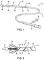
- FIG. 1 Shown in FIG. 1 is one embodiment of a pleated sheath 10 of the present invention mounted near the end of a medical device deployment system 12.
- the deployment system comprises a catheter shaft 14 extending from a distal olive 16 to a control hub 18.
- a medical device such as a stent, stent-graft, balloon, blood filter, occluder, probe, valves, etc., may be contained in the sheath 10 to be deployed at a treatment site within a patient's body.
- the sheath 10 is everted over itself to form two layers, an exterior segment 20 which, in this embodiment, completely covers an interior segment 22.
- the exterior segment is split at its proximal end 24 to form a deployment line 26 that is fed into the catheter shaft through opening 28.
- the deployment line 26 is operatively connected to a deployment knob 30 on the hub 18.
- the sheath 10 may be formed from any material that is sufficiently strong both to constrain the device to be delivered and to withstand the tension of the removal process. It is desirable that the sheath 10 also be as thin and lubricious as possible so as to maintain a small device delivery profile and to facilitate the removal process. Since the sheath 10 is placed temporarily deep within a patient during delivery and deployment, it is likewise desirable that the sheath be formed from a biocompatible material. As is explained in greater detail below, suitable sheath materials may include: polytetrafluoroethylene (PTFE); expanded PTFE (ePTFE); fluorinated ethylene propylene (FEP), polyethylene teraphthalate (PET), nylon, polyurethane, polypropylene, polyester, etc.
- PTFE polytetrafluoroethylene
- ePTFE expanded PTFE
- FEP fluorinated ethylene propylene
- PET polyethylene teraphthalate
- the interior segment 22 includes a helical pleat 32 extending fully along its length.
- the pleat 32 comprises a fold in the material of the sheath that reduces the interior segment 22 of the sheath to a diameter smaller than the diameter of the exterior segment 20.
- a reinforcing material 34 may be layered over or otherwise attached to the sheath.
- such material is fold-resistant so that the pleat more readily holds its correct orientation along its entire length during the folding process and through sheath deployment.
- Suitable reinforcing materials may include: one or more strips of polymer material, such as polyimide, polyethylene teraphthalate (PET), nylon, polyurethane, or similar material, adhered to the sheath; a coating applied to the strip that hardens to provide the desired properties, such as providing sufficient stiffness/Young's Modulus and thickness to resist folding for a given helical pitch, pleat width, and effective diameter.
- polymer material such as polyimide, polyethylene teraphthalate (PET), nylon, polyurethane, or similar material
- each pleat refers to any fold or multiple folds in the sheath material that reduces the effective diameter of the sheath.
- each pleat comprises two folds that cause the sheath material to double back on itself.
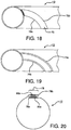
- the pleat may comprise a single fold or multiple folds along an edge of a sheet of material, which may be interlocked, for instance as shown in FIG. 20 .
- a pleat may also be formed through a rolling, twisting, or accordion folding of a section of material or similarly storing material for later un-pleating during deployment.
- the sheath 10 everts over itself at a fold 36 at one end, in this embodiment at the distal end.
- the fold 36 may be oriented at either the distal end or the proximal end of the device, or anywhere in between.
- FIG. 2 The process of device delivery can be better seen in FIG. 2 .
- the interior segment 22 with its reinforced pleats 32 is shown exposed in cut-away.
- the pleats 32 open up along fold 36.
- the strips of reinforcement material 34 Seen along the length of the exterior segment 20 are the strips of reinforcement material 34, now merely attached to the sheath 10 and no longer defining a pleat.
- a constrained self-expanding stent 38 is progressively deployed from this embodiment.
- FIG. 4 shows the process of un-pleating with the contained pleats 32 shown in phantom and the un-pleated reinforcement material 34 shown exposed along the exterior segment 20. Again, transition occurs along fold 36.
- a deployment line 40 is connected to one end 42 of the exterior segment 20. Tension on the deployment line 42 actuates the sheath 10.
- FIG. 5 illustrates another embodiment of the present invention comprising a single layer sheath 10.
- the helically formed pleat 32 again includes a strip of reinforcement material 34.
- the pleat 32 causes the sheath 10 to have a given diameter of x.
- the diameter of the sheath 10 enlarges to increased diameter of y.
- the pleats of the present invention are preferably stable without a constraining force.
- a sufficiently rigid pleat with sufficient helical angle will be inherently stable and will remain in place even without an external constraint.
- constraints can be provided to help retain the pleats in position.
- the single layer sheath may be formed and then everted over itself, either partially or entirely, and then employed in the manner described above. The everted portion of the sheath will maintain the pleats in their folded configuration until the device is ready for deployment.
- the single layer sheath may be contained in another tubular structure to maintain the pleats in a folded configuration, such as through use of another sheath, a closely fitted catheter tube, or similar structure.
- the pleats can be joined to the sheath, such as through use of an adhesive, an adhered tape, a wrapped tape, a wrapped thread, or similar means, that will hold the pleats in position until the device is ready for deployment.
- a further method of deployment of a single layer sheath may include tensioning from the proximal end of the pleated tube (that is, the end closest to the clinician). When sufficient tension is applied, the pleat will unfold and the tube will increase diametrically allowing it to be translated relative to the device.
- FIGS. 8 and 9 Illustrated in FIGS. 8 and 9 is a still another embodiment of a pleated sheath 10 of the present invention.
- the sheath 10 comprises a single layer and includes two pleats 32a, 32b therein.
- the pleats may be evenly aligned on opposite sides of the sheath 10, as shown, or may be placed in other orientations. It should be understood that depending on desired deployment specifications, the present invention can be practiced with one, two, three, four, five or more pleats along part or all of the sheath length.
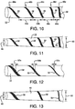
- FIG. 10 illustrates another embodiment of a sheath 10 of the present invention wherein the spacing 44a, 44b, 44c, 44d between pleating elements 32 varies along the length of the sheath 10.
- the pitch 46a, 46b, 46c, 46d, 46e of the helical wraps of the pleating elements 32 also varies along the length of the sheath 10.
- Each of these properties can be adjusted, independently or in cooperation, in device design so as to provide varying diameters along the length of the sheath after pleating. Diameter may be varied along the length of the sheath to accommodate non-cylindrical device profiles and/or produce variable sheath removal properties.
- FIG. 11 depicts the sheath of FIG. 10 after it has been pleated.
- the sheath and contained device provide a tapered profile, with the distal end 48 being a smaller diameter than the proximal end 50.
- width 52a, 52b, 52c of the pleating element is changed along the length of the sheath 10.
- diameter can be varied along the length of the sheath to accommodate non-cylindrical device profiles and/or produce variable sheath removal properties.
- the pleated sheath can be formed with a variable diameter, producing either greater or lesser friction (depending on the direction of deployment) as the sheath is deployed along its length-making it either initially easier or more difficult to deploy the sheath.
- FIG. 13 depicts the sheath of FIG. 12 after it has been pleated.
- the sheath and contained device provide a tapered profile, with the distal end 48 being a smaller diameter than the proximal end 50.
- FIG. 14 Shown in FIG. 14 is a delivery catheter incorporating a pair of sheaths of the present invention and containing a compacted device 38, the pair of sheaths 10a, 10b being oriented to withdraw from a compacted device 38 in opposite directions from a point midway along the device.
- Proximal sheath 10a runs along catheter shaft 14 to an actuation mechanism 54.
- Distal sheath 10b is withdrawn in the opposite direction (that is, towards the distal end of the catheter 14) and is inverted into the catheter shaft 14.
- the distal sheath 10b is likewise controlled by actuation mechanism 54.
- the two sheaths 10a, 10b are withdrawn simultaneously from the compacted device 38 to allow it to deploy from its middle outward.
- Such deployment may be useful in those instances where very rapid device deployment is sought and/or where it is desirable to minimize the effect of high volume of blood flow upon the device prior to full deployment (for instance, when a device is deployed in the aorta and it is desirous to have the upstream end of the device deploy last so as to avoid a "windsock" effect in the high-volume blood flow which may misalign device positioning).
- FIG. 15 illustrates how a stent-graft device 38 can be deployed from its midpoint by removing two sheaths 10a, 10b. This deployment method would be preferred for placing a stent-graft device in a thoracic aorta or the like.
- each of the sheaths 10a, 10b independently of each other so that only part of the device is deployed at any given time. This can be readily accomplished by providing separate actuation mechanisms for each of the sheaths. It should be further appreciated that with respect to all of the embodiments of the present invention discussed herein it may be desirable to have sheath deployment occur either from the distal end of the catheter back or from the proximal end of the catheter forward, or with two or more deployment sheaths moving in opposite directions, as illustrated in the embodiments of FIGS. 14 and 15 .
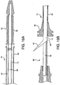
- FIGS. 16A and 16B illustrate a deployment mechanism similar to the one shown in FIG. 14 .
- a single everted sheath 10 is provided constraining a device 38.
- the sheath 10 extends proximally within an outer casing 54 of catheter shaft 14, coaxially surrounding inner catheter shaft 56.
- the sheath 10 extends to the proximal end 58 of the catheter 14, where it can be actuated by a user.
- the sheath 10 is constructed from a material that will split longitudinally, such as through a pre-formed longitudinal line of perforations or similar weakening means 60, so that the sheath 10 can be removed from the inner shaft 56 by applying tension to tail 62, as is shown in FIG. 16B .
- a strain relief 64 may be provided on the distal end of the outer casing 54 to assist in handling of the catheter 14 during placement and deployment.
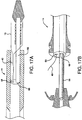
- FIGS. 17A and 17B Another deployment mechanism that may be used with the present invention is shown in FIGS. 17A and 17B .
- a dual lumen catheter 14 is provided, having a lumen 66 for housing inner shaft 56 and a lumen 68 designed to accept a deployment line 40.
- the deployment line 40 is integral with or attached to the sheath 10. The line 40 is actuated to cause the sheath 10 to withdraw in the manner previously described.
- the preferred sheath of the present invention for containing and deploying a self-expanding stent or stent-graft for vascular applications will be constructed of a thin, lubricous polymer material, such as an ePTFE multi-layer laminated film tube, with a thickness of 0.03 to 0.3 mm, and more preferably 0.05 to 0.12 mm.
- a thin, lubricous polymer material such as an ePTFE multi-layer laminated film tube, with a thickness of 0.03 to 0.3 mm, and more preferably 0.05 to 0.12 mm.
- the tube of the present invention is preferably as thin as possible while having strength properties that will withstand loading forces and effectively constrain the device until it is deployed.
- FIG. 18 illustrates a pleat reinforcement 70 that is formed from the same material as the sheath 10 itself.
- Such reinforcement 70 is achieved by providing a layer of additional material along a portion of the sheath circumference so as to provide defined fold lines 72a, 72b on either side of the raised reinforcement 70.
- This construct may be formed by extruding or otherwise adding additional material in the defined manner on the sheath and/or removing material from, or densifying material on, the remainder of the sheath 10 in order to leave a pleat reinforcement 70 of increased dimension.
- a similar effect may be achieved by densifying the reinforcement area in order to establish fold-resistance.
- FIG. 19 illustrates another approach to achieve predictable sheath folding.
- the sheath 10 has been treated to provide one or more defined pleat hinge lines 74a, 74b.
- Each hinge line 74 may be formed through any of a variety of surface treatment means, including through mechanical methods (e.g., cutting, scoring, densification, etc.), through extrusion or other material manufacture steps, or through thermal processing (e.g., through heat or laser treatment), or some combination of such various methods.
- the pleated configuration of the sheath 10 is folded along these hinge lines 74.
- the desired result is achieved by forming a pleat region with sufficient relative stiffness and/or thickness to resist folding or otherwise to fold preferentially. Additionally, using these techniques the sheath can be provided with preferential folding properties without the need to add additional material to the sheath.
- FIG. 20 illustrates still another method of forming a pleat in accordance with the present invention.
- the sheath 10 is formed from a sheet of material having two edges 76a, 76b. Each of these edges 76a, 76b can then be folded to form a pleat 78a, 78b with one or more folds.
- the edge pleats 76a, 76b can then be interlocked with one another, for instance as shown, to create a tubular structure that serves as the sheath 10 of the present invention.
- the edges 76 will separate from each other to provide the desired predictable enlargement of the present invention.
- One or both of the edges 76 can be provided with reinforcement 80a, 80b, such as through one of the methods previously described, in order to facilitate the formation and retention of the pleat 78.
- the exterior segment in the final construct should have an inner diameter that is sufficiently greater than the outer diameter of the interior segment in order to minimize friction between the two segments. That is, in order to minimize interference between the interior segment and the exterior segment, the un-pleated exterior segment should enlarge enough so that its inner diameter comfortably clears the outer diameter of the pleated interior segment. It is preferred that the inner diameter of the exterior segment be 0.1 to 50% larger than the outer diameter of the interior segment, and more preferably 10 to 20% larger.
- a sheath with a wall thickness of about 0.08 mm and an un-pleated a inner diameter of about 2.1 mm will typically be provided with one or more pleats with a pleat width of 0.8 mm to create a pleated interior segment having a outer diameter of about 1.9 mm.
- pleats are provided with a width of 0.3 to 2.0 mm, and more preferably with a width range of 0.6 to 1.3 mm.
- Pleats will typically be oriented helically around the sheath, with a typical pitch angle of 30 to 75 degrees, and more preferably a pitch of 50 to 70 degrees.
- the pleats are preferably reinforced with a strip or strips of relatively fold-resistant material, such as polyimide film, with a thickness of 0.01 to 0.08 mm, and more preferably 0.02 to 0.05 mm.
- the reinforcement material is encapsulated between layers of a laminated sheath, adhered using an adhesive such as FEP or similar material.
- the preferred sheath of the present invention includes one or more pleats helically oriented along part or all of the longitudinal length of the sheath, it should be appreciated that other pleat orientations as likewise contemplated by the present invention. For example, so long as they are adequately constrained or adhered the pleat or pleats may be arranged essentially parallel to the axis of the device. Further, for some applications multiple discontinuous pleats may be provided to achieve suitable deployment properties. Additionally, for some applications it may be desirable to provide pleats along at least a portion of both the interior segment and the exterior segment of the sheath.
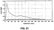
- the sheath of the present invention has been determined to vastly reduce the amount of tension required to deploy a device.
- deployment tensions are typically on the order of 50-150 grams
- this delivery tube could be deployed with significantly less deployment line tension than a comparably constructed everted tube that did not include pleats.
- a conventional tensile test was conducted on an un-pleated everting sheath and a pleated everting sheath of the present invention, the sheaths being otherwise comparable in material and construction, using an INSTRON Tensile Tester employing a crosshead speed of 400 mm/min.
Landscapes
- Health & Medical Sciences (AREA)
- Biomedical Technology (AREA)
- Engineering & Computer Science (AREA)
- Life Sciences & Earth Sciences (AREA)
- Animal Behavior & Ethology (AREA)
- General Health & Medical Sciences (AREA)
- Veterinary Medicine (AREA)
- Heart & Thoracic Surgery (AREA)
- Public Health (AREA)
- Vascular Medicine (AREA)
- Cardiology (AREA)
- Oral & Maxillofacial Surgery (AREA)
- Transplantation (AREA)
- Surgery (AREA)
- Pathology (AREA)
- Molecular Biology (AREA)
- Medical Informatics (AREA)
- Nuclear Medicine, Radiotherapy & Molecular Imaging (AREA)
- Prostheses (AREA)
- Media Introduction/Drainage Providing Device (AREA)
- Materials For Medical Uses (AREA)
Applications Claiming Priority (2)
| Application Number | Priority Date | Filing Date | Title |
|---|---|---|---|
| US12/014,536 US8845712B2 (en) | 2008-01-15 | 2008-01-15 | Pleated deployment sheath |
| PCT/US2009/000321 WO2009091603A1 (en) | 2008-01-15 | 2009-01-15 | Pleated deployment sheath |
Publications (2)
| Publication Number | Publication Date |
|---|---|
| EP2249749A1 EP2249749A1 (en) | 2010-11-17 |
| EP2249749B1 true EP2249749B1 (en) | 2016-04-13 |
Family
ID=40592085
Family Applications (1)
| Application Number | Title | Priority Date | Filing Date |
|---|---|---|---|
| EP09701688.5A Active EP2249749B1 (en) | 2008-01-15 | 2009-01-15 | Pleated deployment sheath |
Country Status (7)
| Country | Link |
|---|---|
| US (2) | US8845712B2 (enExample) |
| EP (1) | EP2249749B1 (enExample) |
| JP (1) | JP5710981B2 (enExample) |
| AU (1) | AU2009205667B2 (enExample) |
| CA (1) | CA2711507C (enExample) |
| ES (1) | ES2581936T3 (enExample) |
| WO (1) | WO2009091603A1 (enExample) |
Families Citing this family (29)
| Publication number | Priority date | Publication date | Assignee | Title |
|---|---|---|---|---|
| DE102008021060A1 (de) * | 2008-04-26 | 2009-10-29 | Biotronik Vi Patent Ag | Einführvorrichtung mit einer Freisetzeinrichtung zur Freisetzung eines von einem Katheter getragenen Gegenstandes sowie Freisetzeinrichtung einer Einführvorrichtung |
| US10045868B2 (en) * | 2009-03-04 | 2018-08-14 | W. L. Gore & Associates Inc. | Atraumatic vascular graft removal sheath |
| US8326437B2 (en) | 2009-03-04 | 2012-12-04 | W. L. Gore & Associates, Inc. | Atraumatic lead removal sheath |
| AU2012209013B2 (en) * | 2011-08-02 | 2013-11-14 | Cook Medical Technologies Llc | Delivery device having a variable diameter introducer sheath |
| US10213329B2 (en) | 2011-08-12 | 2019-02-26 | W. L. Gore & Associates, Inc. | Evertable sheath devices, systems, and methods |
| US9877858B2 (en) | 2011-11-14 | 2018-01-30 | W. L. Gore & Associates, Inc. | External steerable fiber for use in endoluminal deployment of expandable devices |
| US9782282B2 (en) * | 2011-11-14 | 2017-10-10 | W. L. Gore & Associates, Inc. | External steerable fiber for use in endoluminal deployment of expandable devices |
| US9364358B2 (en) | 2012-07-27 | 2016-06-14 | Medinol Ltd. | Catheter with retractable cover and pressurized fluid |
| US20140172068A1 (en) * | 2012-12-17 | 2014-06-19 | Cook Medical Technologies Llc | Restraining sheath with variable diameter medical device nesting region |
| US9849015B2 (en) * | 2012-12-28 | 2017-12-26 | Cook Medical Technologies Llc | Endoluminal prosthesis introducer |
| US9907641B2 (en) | 2014-01-10 | 2018-03-06 | W. L. Gore & Associates, Inc. | Implantable intraluminal device |
| US9763819B1 (en) * | 2013-03-05 | 2017-09-19 | W. L. Gore & Associates, Inc. | Tapered sleeve |
| US9539411B2 (en) | 2013-03-13 | 2017-01-10 | W. L. Gore & Associates, Inc. | Deconstructable endoluminal devices and related systems and methods |
| US9226839B1 (en) * | 2013-03-14 | 2016-01-05 | W. L. Gore & Associates, Inc. | Torque sleeve |
| ES2768675T3 (es) | 2013-05-03 | 2020-06-23 | Bard Inc C R | Vaina protectora desprendible |
| US10966850B2 (en) * | 2014-03-06 | 2021-04-06 | W. L. Gore & Associates, Inc. | Implantable medical device constraint and deployment apparatus |
| US10758387B2 (en) | 2014-10-16 | 2020-09-01 | Cook Medical Technologies Llc | Endovascular stent graft assembly and delivery device |
| US10959826B2 (en) | 2014-10-16 | 2021-03-30 | Cook Medical Technology LLC | Support structure for scalloped grafts |
| US10258492B2 (en) | 2017-03-03 | 2019-04-16 | Cook Medical Technologies Llc | Prosthesis delivery system with axially collapsible sheath |
| WO2018165358A1 (en) | 2017-03-08 | 2018-09-13 | W. L. Gore & Associates, Inc. | Steering wire attach for angulation |
| WO2018231907A1 (en) * | 2017-06-13 | 2018-12-20 | Boston Scientific Scimed, Inc. | Introducer with expandable capabilities |
| ES2960532T3 (es) | 2017-10-11 | 2024-03-05 | Gore & Ass | Aparato de restricción y despliegue de dispositivos médicos implantables |
| WO2019199703A1 (en) * | 2018-04-09 | 2019-10-17 | Boston Scientific Scimed, Inc. | Stent delivery system with reduced deployment force |
| CN112638320B (zh) | 2018-08-31 | 2024-07-30 | W.L.戈尔及同仁股份有限公司 | 用于使可植入医疗装置转向的设备、系统和方法 |
| US11389627B1 (en) | 2018-10-02 | 2022-07-19 | Lutonix Inc. | Balloon protectors, balloon-catheter assemblies, and methods thereof |
| US11259944B2 (en) | 2019-06-27 | 2022-03-01 | Cook Medical Technologies Llc | Stent deployment system with unwrapping deployment constraint |
| WO2021154421A1 (en) * | 2020-01-27 | 2021-08-05 | Boston Scientific Scimed, Inc. | Stent deployment system |
| JP7549147B2 (ja) * | 2021-07-05 | 2024-09-10 | 日本ライフライン株式会社 | 治療装置 |
| US11969188B1 (en) | 2023-09-18 | 2024-04-30 | Laplace Interventional Inc. | Dilating introducer devices and methods for vascular access |
Family Cites Families (105)
| Publication number | Priority date | Publication date | Assignee | Title |
|---|---|---|---|---|
| US3225129A (en) | 1962-06-26 | 1965-12-21 | Budd Co | Method of making memory re-shaped plastic tubes, especially fluorocarbon cylinder jackets |
| US4141364A (en) | 1977-03-18 | 1979-02-27 | Jorge Schultze | Expandable endotracheal or urethral tube |
| US4411655A (en) * | 1981-11-30 | 1983-10-25 | Schreck David M | Apparatus and method for percutaneous catheterization |
| SE445884B (sv) | 1982-04-30 | 1986-07-28 | Medinvent Sa | Anordning for implantation av en rorformig protes |
| US4569347A (en) * | 1984-05-30 | 1986-02-11 | Advanced Cardiovascular Systems, Inc. | Catheter introducing device, assembly and method |
| ES8705239A1 (es) | 1984-12-05 | 1987-05-01 | Medinvent Sa | Un dispositivo para implantar,mediante insercion en un lugarde dificil acceso, una protesis sustancialmente tubular y radialmente expandible |
| US4601713A (en) * | 1985-06-11 | 1986-07-22 | Genus Catheter Technologies, Inc. | Variable diameter catheter |
| US4738666A (en) * | 1985-06-11 | 1988-04-19 | Genus Catheter Technologies, Inc. | Variable diameter catheter |
| SE454482B (sv) | 1986-09-30 | 1988-05-09 | Medinvent Sa | Anordning for implantation |
| SE455834B (sv) | 1986-10-31 | 1988-08-15 | Medinvent Sa | Anordning for transluminal implantation av en i huvudsak rorformig, radiellt expanderbar protes |
| US4921479A (en) * | 1987-10-02 | 1990-05-01 | Joseph Grayzel | Catheter sheath with longitudinal seam |
| US5234425A (en) | 1989-03-03 | 1993-08-10 | Thomas J. Fogarty | Variable diameter sheath method and apparatus for use in body passages |
| US5171262A (en) | 1989-06-15 | 1992-12-15 | Cordis Corporation | Non-woven endoprosthesis |
| US5066298A (en) * | 1989-11-30 | 1991-11-19 | Progressive Angioplasty Systems, Inc. | Article and method of sheathing angioplasty balloons |
| GB2240926A (en) * | 1990-02-14 | 1991-08-21 | Steven Streatfield Gill | An expansible cannula |
| DE4018525C2 (de) * | 1990-06-09 | 1994-05-05 | Kaltenbach Martin | Katheter mit einem aufweitbaren Bereich |
| US5201756A (en) | 1990-06-20 | 1993-04-13 | Danforth Biomedical, Inc. | Radially-expandable tubular elements for use in the construction of medical devices |
| US5176659A (en) * | 1991-02-28 | 1993-01-05 | Mario Mancini | Expandable intravenous catheter and method of using |
| FR2679484B1 (fr) | 1991-07-26 | 1995-02-17 | Plastic Omnium Cie | Procede pour la realisation de tubes en resine fluoree, notamment en polytetrafluorethylene. |
| US5447503A (en) * | 1991-08-14 | 1995-09-05 | Cordis Corporation | Guiding catheter tip having a tapered tip with an expandable lumen |
| US5171305A (en) * | 1991-10-17 | 1992-12-15 | Imagyn Medical, Inc. | Linear eversion catheter with reinforced inner body extension |
| US5364345A (en) | 1991-10-18 | 1994-11-15 | Imagyn Medical, Inc. | Method of tubal recanalization and catheter system therefor |
| US5395349A (en) | 1991-12-13 | 1995-03-07 | Endovascular Technologies, Inc. | Dual valve reinforced sheath and method |
| US6652492B1 (en) * | 1991-12-13 | 2003-11-25 | Endovascular Technologies, Inc. | Dual valve, flexible sheath and method |
| US5507767A (en) | 1992-01-15 | 1996-04-16 | Cook Incorporated | Spiral stent |
| US5683448A (en) | 1992-02-21 | 1997-11-04 | Boston Scientific Technology, Inc. | Intraluminal stent and graft |
| US5405377A (en) | 1992-02-21 | 1995-04-11 | Endotech Ltd. | Intraluminal stent |
| US5458573A (en) | 1992-05-01 | 1995-10-17 | American Biomed, Inc. | Everting toposcopic dilation catheter |
| US5352236A (en) * | 1992-09-29 | 1994-10-04 | Medtronic, Inc. | Balloon protector |
| JPH08500757A (ja) | 1992-12-30 | 1996-01-30 | シュナイダー・(ユーエスエイ)・インコーポレーテッド | 身体に移植可能なステントを展開する装置 |
| US5328469A (en) | 1993-03-19 | 1994-07-12 | Roger Coletti | Hybrid balloon angioplasty catheter and methods of use |
| NL9300500A (nl) * | 1993-03-22 | 1994-10-17 | Industrial Res Bv | Uitzetbare, holle huls voor het plaatselijk ondersteunen en/of versterken van een lichaamsvat, alsmede werkwijze voor het vervaardigen daarvan. |
| US6025044A (en) | 1993-08-18 | 2000-02-15 | W. L. Gore & Associates, Inc. | Thin-wall polytetrafluoroethylene tube |
| US5445646A (en) * | 1993-10-22 | 1995-08-29 | Scimed Lifesystems, Inc. | Single layer hydraulic sheath stent delivery apparatus and method |
| US5571135A (en) | 1993-10-22 | 1996-11-05 | Scimed Life Systems Inc. | Stent delivery apparatus and method |
| US5789047A (en) | 1993-12-21 | 1998-08-04 | Japan Gore-Tex, Inc | Flexible, multilayered tube |
| ATE151258T1 (de) | 1994-04-26 | 1997-04-15 | Ruesch Willy Ag | Selbstexpandierender stent für hohlorgane |
| US5476508A (en) | 1994-05-26 | 1995-12-19 | Tfx Medical | Stent with mutually interlocking filaments |
| US5569183A (en) * | 1994-06-01 | 1996-10-29 | Archimedes Surgical, Inc. | Method for performing surgery around a viewing space in the interior of the body |
| US5824041A (en) | 1994-06-08 | 1998-10-20 | Medtronic, Inc. | Apparatus and methods for placement and repositioning of intraluminal prostheses |
| ATE232067T1 (de) * | 1995-04-14 | 2003-02-15 | Boston Scient Ltd | Stentanbringungsvorrichtung mit rollmembran |
| US5641373A (en) | 1995-04-17 | 1997-06-24 | Baxter International Inc. | Method of manufacturing a radially-enlargeable PTFE tape-reinforced vascular graft |
| DE69635112T2 (de) | 1995-07-07 | 2006-05-18 | W.L. Gore & Associates, Inc., Newark | Innenbeschichtung für rohre und blutgefässe |
| US6042605A (en) | 1995-12-14 | 2000-03-28 | Gore Enterprose Holdings, Inc. | Kink resistant stent-graft |
| US5997508A (en) * | 1996-03-28 | 1999-12-07 | Medtronic, Inc. | Expandable percutaneous introducer sheath |
| US5833699A (en) | 1996-04-10 | 1998-11-10 | Chuter; Timothy A. M. | Extending ribbon stent |
| CA2211249C (en) * | 1996-07-24 | 2007-07-17 | Cordis Corporation | Balloon catheter and methods of use |
| US5868707A (en) * | 1996-08-15 | 1999-02-09 | Advanced Cardiovascular Systems, Inc. | Protective sheath for catheter balloons |
| US6254628B1 (en) * | 1996-12-09 | 2001-07-03 | Micro Therapeutics, Inc. | Intracranial stent |
| EP0952795B1 (en) * | 1996-11-15 | 2007-01-03 | Cook Incorporated | Splittable sleeve, stent deployment device |
| US5993427A (en) | 1996-12-03 | 1999-11-30 | Laborie Medical Technologies Corp. | Everting tube structure |
| US6352561B1 (en) * | 1996-12-23 | 2002-03-05 | W. L. Gore & Associates | Implant deployment apparatus |
| DE19703482A1 (de) | 1997-01-31 | 1998-08-06 | Ernst Peter Prof Dr M Strecker | Stent |
| US5893868A (en) * | 1997-03-05 | 1999-04-13 | Scimed Life Systems, Inc. | Catheter with removable balloon protector and stent delivery system with removable stent protector |
| US6110146A (en) * | 1998-09-30 | 2000-08-29 | Medtronic Ave, Inc. | Protector for catheter balloon with guidewire backloading system |
| US6059813A (en) | 1998-11-06 | 2000-05-09 | Scimed Life Systems, Inc. | Rolling membrane stent delivery system |
| US6544278B1 (en) | 1998-11-06 | 2003-04-08 | Scimed Life Systems, Inc. | Rolling membrane stent delivery system |
| AU1405600A (en) * | 1998-12-01 | 2000-06-19 | Atropos Limited | A medical device comprising an evertable sleeve |
| US6719805B1 (en) | 1999-06-09 | 2004-04-13 | C. R. Bard, Inc. | Devices and methods for treating tissue |
| US6280412B1 (en) * | 1999-06-17 | 2001-08-28 | Scimed Life Systems, Inc. | Stent securement by balloon modification |
| JP3804351B2 (ja) | 1999-08-25 | 2006-08-02 | ニプロ株式会社 | バルーンカテーテル |
| US6371980B1 (en) * | 1999-08-30 | 2002-04-16 | Cardiovasc, Inc. | Composite expandable device with impervious polymeric covering and bioactive coating thereon, delivery apparatus and method |
| AUPQ641400A0 (en) | 2000-03-23 | 2000-04-15 | Kleiner, Daniel E. | A device incorporating a hollow member for being positioned along a body cavity of a patient and method of positioning same |
| US6432130B1 (en) * | 2000-04-20 | 2002-08-13 | Scimed Life Systems, Inc. | Fully sheathed balloon expandable stent delivery system |
| US6387118B1 (en) * | 2000-04-20 | 2002-05-14 | Scimed Life Systems, Inc. | Non-crimped stent delivery system |
| US6607552B1 (en) * | 2000-09-18 | 2003-08-19 | Scimed Life Systems, Inc. | Rolling socks |
| US6899727B2 (en) * | 2001-01-22 | 2005-05-31 | Gore Enterprise Holdings, Inc. | Deployment system for intraluminal devices |
| US6783542B2 (en) | 2001-02-22 | 2004-08-31 | Scimed Life Systems, Inc | Crimpable balloon/stent protector |
| US6547813B2 (en) * | 2001-03-23 | 2003-04-15 | Medtronic Ave, Inc. | Stent delivery catheter with folded sleeve and method of making same |
| JP4043210B2 (ja) | 2001-10-09 | 2008-02-06 | オリンパス株式会社 | ステント |
| AU2002357045A1 (en) | 2001-11-28 | 2003-06-10 | Benjamin S. Hsiao | Endovascular graft and graft trimmer |
| US20050228479A1 (en) | 2001-11-29 | 2005-10-13 | Cook Incorporated | Medical device delivery system |
| US6866679B2 (en) | 2002-03-12 | 2005-03-15 | Ev3 Inc. | Everting stent and stent delivery system |
| US6939327B2 (en) * | 2002-05-07 | 2005-09-06 | Cardiac Pacemakers, Inc. | Peel-away sheath |
| DE60315460T2 (de) * | 2002-06-28 | 2008-04-30 | Cook Critical Care, Bloomington | Einführungshülse |
| US7115138B2 (en) * | 2002-09-04 | 2006-10-03 | Boston Scientific Scimed, Inc. | Sheath tip |
| WO2004034767A2 (en) * | 2002-09-20 | 2004-04-29 | Flowmedica, Inc. | Catheter system for renal therapy |
| US7105013B2 (en) * | 2002-09-30 | 2006-09-12 | Advanced Cardiovascular Systems, Inc. | Protective sleeve assembly for a balloon catheter |
| US7766820B2 (en) * | 2002-10-25 | 2010-08-03 | Nmt Medical, Inc. | Expandable sheath tubing |
| US7198636B2 (en) | 2003-01-17 | 2007-04-03 | Gore Enterprise Holdings, Inc. | Deployment system for an endoluminal device |
| US7753945B2 (en) | 2003-01-17 | 2010-07-13 | Gore Enterprise Holdings, Inc. | Deployment system for an endoluminal device |
| US7625337B2 (en) * | 2003-01-17 | 2009-12-01 | Gore Enterprise Holdings, Inc. | Catheter assembly |
| GB0310714D0 (en) | 2003-05-09 | 2003-06-11 | Angiomed Ag | Fluid flow management in stent delivery system |
| US8292943B2 (en) | 2003-09-03 | 2012-10-23 | Bolton Medical, Inc. | Stent graft with longitudinal support member |
| US7780692B2 (en) * | 2003-12-05 | 2010-08-24 | Onset Medical Corporation | Expandable percutaneous sheath |
| US7699864B2 (en) * | 2004-03-18 | 2010-04-20 | Onset Medical Corporation | Expandable medical access device |
| US20050246008A1 (en) | 2004-04-30 | 2005-11-03 | Novostent Corporation | Delivery system for vascular prostheses and methods of use |
| EP1750619B1 (en) | 2004-05-25 | 2013-07-24 | Covidien LP | Flexible vascular occluding device |
| EP1621160B1 (en) | 2004-07-28 | 2008-03-26 | Cordis Corporation | Low deployment force delivery device |
| US7955370B2 (en) * | 2004-08-06 | 2011-06-07 | Boston Scientific Scimed, Inc. | Stent delivery system |
| US7393358B2 (en) * | 2004-08-17 | 2008-07-01 | Boston Scientific Scimed, Inc. | Stent delivery system |
| US7691137B2 (en) | 2004-09-28 | 2010-04-06 | Boston Scientific Scimed, Inc. | Rotatable sheath, assembly and method of manufacture of same |
| US7578838B2 (en) | 2005-01-12 | 2009-08-25 | Cook Incorporated | Delivery system with helical shaft |
| US20060184225A1 (en) | 2005-02-11 | 2006-08-17 | Medtronic Vascular, Inc. | Force distributing system for delivering a self-expanding stent |
| US7918880B2 (en) | 2005-02-16 | 2011-04-05 | Boston Scientific Scimed, Inc. | Self-expanding stent and delivery system |
| US7632296B2 (en) * | 2005-03-03 | 2009-12-15 | Boston Scientific Scimed, Inc. | Rolling membrane with hydraulic recapture means for self expanding stent |
| US8435279B2 (en) | 2005-06-14 | 2013-05-07 | Advanced Cardiovascular Systems, Inc. | Delivery system for a device such as a stent |
| US9375215B2 (en) * | 2006-01-20 | 2016-06-28 | W. L. Gore & Associates, Inc. | Device for rapid repair of body conduits |
| US7785290B2 (en) | 2006-08-07 | 2010-08-31 | Gore Enterprise Holdings, Inc. | Non-shortening high angle wrapped balloons |
| US7780630B2 (en) * | 2007-03-30 | 2010-08-24 | Boston Scientific Scimed, Inc. | Perfusion device |
| US8372138B2 (en) | 2007-06-12 | 2013-02-12 | Boston Scientific Scimed, Inc. | Shape memory polymeric stent |
| WO2009002827A2 (en) | 2007-06-22 | 2008-12-31 | Cr Bard Inc | Helical and segmented stent-graft |
| DE102008048416A1 (de) | 2008-08-05 | 2010-02-11 | Acandis Gmbh & Co. Kg | Medizinische Vorrichtung und Verfahren zum Herstellen einer derartigen Vorrichtung |
| DE102008048417A1 (de) | 2008-09-23 | 2010-04-01 | Acandis Gmbh & Co. Kg | Medizinische Vorrichtung |
| US8435282B2 (en) | 2009-07-15 | 2013-05-07 | W. L. Gore & Associates, Inc. | Tube with reverse necking properties |
-
2008
- 2008-01-15 US US12/014,536 patent/US8845712B2/en active Active
-
2009
- 2009-01-15 WO PCT/US2009/000321 patent/WO2009091603A1/en not_active Ceased
- 2009-01-15 EP EP09701688.5A patent/EP2249749B1/en active Active
- 2009-01-15 AU AU2009205667A patent/AU2009205667B2/en not_active Ceased
- 2009-01-15 JP JP2010543148A patent/JP5710981B2/ja not_active Expired - Fee Related
- 2009-01-15 ES ES09701688.5T patent/ES2581936T3/es active Active
- 2009-01-15 CA CA2711507A patent/CA2711507C/en active Active
-
2013
- 2013-03-15 US US13/843,800 patent/US20130296877A1/en not_active Abandoned
Also Published As
| Publication number | Publication date |
|---|---|
| JP2011509744A (ja) | 2011-03-31 |
| HK1150530A1 (zh) | 2012-01-06 |
| CA2711507C (en) | 2013-04-16 |
| WO2009091603A1 (en) | 2009-07-23 |
| AU2009205667A1 (en) | 2009-07-23 |
| AU2009205667B2 (en) | 2012-05-31 |
| EP2249749A1 (en) | 2010-11-17 |
| US20090182411A1 (en) | 2009-07-16 |
| CA2711507A1 (en) | 2009-07-23 |
| JP5710981B2 (ja) | 2015-04-30 |
| US8845712B2 (en) | 2014-09-30 |
| ES2581936T3 (es) | 2016-09-08 |
| US20130296877A1 (en) | 2013-11-07 |
Similar Documents
| Publication | Publication Date | Title |
|---|---|---|
| EP2249749B1 (en) | Pleated deployment sheath | |
| US12447030B2 (en) | Evertable sheath devices, systems, and methods | |
| CA2767540C (en) | Tube with reverse necking properties | |
| EP0943302B1 (en) | Delivery catheter for positioning an endoluminal prosthesis | |
| JP5529841B2 (ja) | 拡張可能なデバイス用の展開システム | |
| US20060142838A1 (en) | Medical devices including metallic films and methods for loading and deploying same | |
| HK1150530B (en) | Pleated deployment sheath | |
| AU2012216515A1 (en) | Pleated deployment sheath | |
| HK1164680B (en) | Tube with reverse necking properties | |
| HK1198808B (en) | Evertable sheath devices and systems |
Legal Events
| Date | Code | Title | Description |
|---|---|---|---|
| PUAI | Public reference made under article 153(3) epc to a published international application that has entered the european phase |
Free format text: ORIGINAL CODE: 0009012 |
|
| 17P | Request for examination filed |
Effective date: 20100811 |
|
| AK | Designated contracting states |
Kind code of ref document: A1 Designated state(s): AT BE BG CH CY CZ DE DK EE ES FI FR GB GR HR HU IE IS IT LI LT LU LV MC MK MT NL NO PL PT RO SE SI SK TR |
|
| AX | Request for extension of the european patent |
Extension state: AL BA RS |
|
| DAX | Request for extension of the european patent (deleted) | ||
| RIN1 | Information on inventor provided before grant (corrected) |
Inventor name: IRWIN, CRAIG, W. Inventor name: SILVERMAN, JAMES, D. |
|
| REG | Reference to a national code |
Ref country code: HK Ref legal event code: DE Ref document number: 1150530 Country of ref document: HK |
|
| 17Q | First examination report despatched |
Effective date: 20130709 |
|
| REG | Reference to a national code |
Ref country code: DE Ref legal event code: R079 Ref document number: 602009037716 Country of ref document: DE Free format text: PREVIOUS MAIN CLASS: A61F0002840000 Ipc: A61F0002966000 |
|
| RIC1 | Information provided on ipc code assigned before grant |
Ipc: A61F 2/966 20130101AFI20150831BHEP |
|
| RAP1 | Party data changed (applicant data changed or rights of an application transferred) |
Owner name: W.L. GORE & ASSOCIATES, INC. |
|
| GRAP | Despatch of communication of intention to grant a patent |
Free format text: ORIGINAL CODE: EPIDOSNIGR1 |
|
| INTG | Intention to grant announced |
Effective date: 20151111 |
|
| GRAS | Grant fee paid |
Free format text: ORIGINAL CODE: EPIDOSNIGR3 |
|
| GRAA | (expected) grant |
Free format text: ORIGINAL CODE: 0009210 |
|
| AK | Designated contracting states |
Kind code of ref document: B1 Designated state(s): AT BE BG CH CY CZ DE DK EE ES FI FR GB GR HR HU IE IS IT LI LT LU LV MC MK MT NL NO PL PT RO SE SI SK TR |
|
| REG | Reference to a national code |
Ref country code: GB Ref legal event code: FG4D |
|
| REG | Reference to a national code |
Ref country code: AT Ref legal event code: REF Ref document number: 789263 Country of ref document: AT Kind code of ref document: T Effective date: 20160415 Ref country code: CH Ref legal event code: EP |
|
| REG | Reference to a national code |
Ref country code: IE Ref legal event code: FG4D |
|
| REG | Reference to a national code |
Ref country code: DE Ref legal event code: R096 Ref document number: 602009037716 Country of ref document: DE |
|
| REG | Reference to a national code |
Ref country code: LT Ref legal event code: MG4D |
|
| REG | Reference to a national code |
Ref country code: ES Ref legal event code: FG2A Ref document number: 2581936 Country of ref document: ES Kind code of ref document: T3 Effective date: 20160908 |
|
| REG | Reference to a national code |
Ref country code: AT Ref legal event code: MK05 Ref document number: 789263 Country of ref document: AT Kind code of ref document: T Effective date: 20160413 |
|
| REG | Reference to a national code |
Ref country code: NL Ref legal event code: MP Effective date: 20160413 |
|
| PG25 | Lapsed in a contracting state [announced via postgrant information from national office to epo] |
Ref country code: FI Free format text: LAPSE BECAUSE OF FAILURE TO SUBMIT A TRANSLATION OF THE DESCRIPTION OR TO PAY THE FEE WITHIN THE PRESCRIBED TIME-LIMIT Effective date: 20160413 Ref country code: NO Free format text: LAPSE BECAUSE OF FAILURE TO SUBMIT A TRANSLATION OF THE DESCRIPTION OR TO PAY THE FEE WITHIN THE PRESCRIBED TIME-LIMIT Effective date: 20160713 Ref country code: LT Free format text: LAPSE BECAUSE OF FAILURE TO SUBMIT A TRANSLATION OF THE DESCRIPTION OR TO PAY THE FEE WITHIN THE PRESCRIBED TIME-LIMIT Effective date: 20160413 Ref country code: NL Free format text: LAPSE BECAUSE OF FAILURE TO SUBMIT A TRANSLATION OF THE DESCRIPTION OR TO PAY THE FEE WITHIN THE PRESCRIBED TIME-LIMIT Effective date: 20160413 Ref country code: PL Free format text: LAPSE BECAUSE OF FAILURE TO SUBMIT A TRANSLATION OF THE DESCRIPTION OR TO PAY THE FEE WITHIN THE PRESCRIBED TIME-LIMIT Effective date: 20160413 |
|
| PG25 | Lapsed in a contracting state [announced via postgrant information from national office to epo] |
Ref country code: LV Free format text: LAPSE BECAUSE OF FAILURE TO SUBMIT A TRANSLATION OF THE DESCRIPTION OR TO PAY THE FEE WITHIN THE PRESCRIBED TIME-LIMIT Effective date: 20160413 Ref country code: AT Free format text: LAPSE BECAUSE OF FAILURE TO SUBMIT A TRANSLATION OF THE DESCRIPTION OR TO PAY THE FEE WITHIN THE PRESCRIBED TIME-LIMIT Effective date: 20160413 Ref country code: HR Free format text: LAPSE BECAUSE OF FAILURE TO SUBMIT A TRANSLATION OF THE DESCRIPTION OR TO PAY THE FEE WITHIN THE PRESCRIBED TIME-LIMIT Effective date: 20160413 Ref country code: SE Free format text: LAPSE BECAUSE OF FAILURE TO SUBMIT A TRANSLATION OF THE DESCRIPTION OR TO PAY THE FEE WITHIN THE PRESCRIBED TIME-LIMIT Effective date: 20160413 Ref country code: GR Free format text: LAPSE BECAUSE OF FAILURE TO SUBMIT A TRANSLATION OF THE DESCRIPTION OR TO PAY THE FEE WITHIN THE PRESCRIBED TIME-LIMIT Effective date: 20160714 Ref country code: PT Free format text: LAPSE BECAUSE OF FAILURE TO SUBMIT A TRANSLATION OF THE DESCRIPTION OR TO PAY THE FEE WITHIN THE PRESCRIBED TIME-LIMIT Effective date: 20160816 |
|
| REG | Reference to a national code |
Ref country code: FR Ref legal event code: PLFP Year of fee payment: 9 |
|
| PG25 | Lapsed in a contracting state [announced via postgrant information from national office to epo] |
Ref country code: BE Free format text: LAPSE BECAUSE OF FAILURE TO SUBMIT A TRANSLATION OF THE DESCRIPTION OR TO PAY THE FEE WITHIN THE PRESCRIBED TIME-LIMIT Effective date: 20160413 |
|
| REG | Reference to a national code |
Ref country code: DE Ref legal event code: R097 Ref document number: 602009037716 Country of ref document: DE |
|
| PG25 | Lapsed in a contracting state [announced via postgrant information from national office to epo] |
Ref country code: EE Free format text: LAPSE BECAUSE OF FAILURE TO SUBMIT A TRANSLATION OF THE DESCRIPTION OR TO PAY THE FEE WITHIN THE PRESCRIBED TIME-LIMIT Effective date: 20160413 Ref country code: SK Free format text: LAPSE BECAUSE OF FAILURE TO SUBMIT A TRANSLATION OF THE DESCRIPTION OR TO PAY THE FEE WITHIN THE PRESCRIBED TIME-LIMIT Effective date: 20160413 Ref country code: RO Free format text: LAPSE BECAUSE OF FAILURE TO SUBMIT A TRANSLATION OF THE DESCRIPTION OR TO PAY THE FEE WITHIN THE PRESCRIBED TIME-LIMIT Effective date: 20160413 Ref country code: CZ Free format text: LAPSE BECAUSE OF FAILURE TO SUBMIT A TRANSLATION OF THE DESCRIPTION OR TO PAY THE FEE WITHIN THE PRESCRIBED TIME-LIMIT Effective date: 20160413 Ref country code: DK Free format text: LAPSE BECAUSE OF FAILURE TO SUBMIT A TRANSLATION OF THE DESCRIPTION OR TO PAY THE FEE WITHIN THE PRESCRIBED TIME-LIMIT Effective date: 20160413 |
|
| PLBE | No opposition filed within time limit |
Free format text: ORIGINAL CODE: 0009261 |
|
| STAA | Information on the status of an ep patent application or granted ep patent |
Free format text: STATUS: NO OPPOSITION FILED WITHIN TIME LIMIT |
|
| 26N | No opposition filed |
Effective date: 20170116 |
|
| PG25 | Lapsed in a contracting state [announced via postgrant information from national office to epo] |
Ref country code: SI Free format text: LAPSE BECAUSE OF FAILURE TO SUBMIT A TRANSLATION OF THE DESCRIPTION OR TO PAY THE FEE WITHIN THE PRESCRIBED TIME-LIMIT Effective date: 20160413 |
|
| REG | Reference to a national code |
Ref country code: HK Ref legal event code: GR Ref document number: 1150530 Country of ref document: HK |
|
| REG | Reference to a national code |
Ref country code: CH Ref legal event code: PL |
|
| PG25 | Lapsed in a contracting state [announced via postgrant information from national office to epo] |
Ref country code: MC Free format text: LAPSE BECAUSE OF FAILURE TO SUBMIT A TRANSLATION OF THE DESCRIPTION OR TO PAY THE FEE WITHIN THE PRESCRIBED TIME-LIMIT Effective date: 20160413 |
|
| PG25 | Lapsed in a contracting state [announced via postgrant information from national office to epo] |
Ref country code: CH Free format text: LAPSE BECAUSE OF NON-PAYMENT OF DUE FEES Effective date: 20170131 Ref country code: LI Free format text: LAPSE BECAUSE OF NON-PAYMENT OF DUE FEES Effective date: 20170131 |
|
| PG25 | Lapsed in a contracting state [announced via postgrant information from national office to epo] |
Ref country code: LU Free format text: LAPSE BECAUSE OF NON-PAYMENT OF DUE FEES Effective date: 20170115 |
|
| REG | Reference to a national code |
Ref country code: FR Ref legal event code: PLFP Year of fee payment: 10 |
|
| PG25 | Lapsed in a contracting state [announced via postgrant information from national office to epo] |
Ref country code: MT Free format text: LAPSE BECAUSE OF NON-PAYMENT OF DUE FEES Effective date: 20170115 |
|
| PG25 | Lapsed in a contracting state [announced via postgrant information from national office to epo] |
Ref country code: HU Free format text: LAPSE BECAUSE OF FAILURE TO SUBMIT A TRANSLATION OF THE DESCRIPTION OR TO PAY THE FEE WITHIN THE PRESCRIBED TIME-LIMIT; INVALID AB INITIO Effective date: 20090115 |
|
| PG25 | Lapsed in a contracting state [announced via postgrant information from national office to epo] |
Ref country code: BG Free format text: LAPSE BECAUSE OF FAILURE TO SUBMIT A TRANSLATION OF THE DESCRIPTION OR TO PAY THE FEE WITHIN THE PRESCRIBED TIME-LIMIT Effective date: 20160413 |
|
| PG25 | Lapsed in a contracting state [announced via postgrant information from national office to epo] |
Ref country code: CY Free format text: LAPSE BECAUSE OF NON-PAYMENT OF DUE FEES Effective date: 20160413 |
|
| PG25 | Lapsed in a contracting state [announced via postgrant information from national office to epo] |
Ref country code: MK Free format text: LAPSE BECAUSE OF FAILURE TO SUBMIT A TRANSLATION OF THE DESCRIPTION OR TO PAY THE FEE WITHIN THE PRESCRIBED TIME-LIMIT Effective date: 20160413 |
|
| PG25 | Lapsed in a contracting state [announced via postgrant information from national office to epo] |
Ref country code: TR Free format text: LAPSE BECAUSE OF FAILURE TO SUBMIT A TRANSLATION OF THE DESCRIPTION OR TO PAY THE FEE WITHIN THE PRESCRIBED TIME-LIMIT Effective date: 20160413 |
|
| PG25 | Lapsed in a contracting state [announced via postgrant information from national office to epo] |
Ref country code: IS Free format text: LAPSE BECAUSE OF FAILURE TO SUBMIT A TRANSLATION OF THE DESCRIPTION OR TO PAY THE FEE WITHIN THE PRESCRIBED TIME-LIMIT Effective date: 20160813 |
|
| PGFP | Annual fee paid to national office [announced via postgrant information from national office to epo] |
Ref country code: IE Payment date: 20221222 Year of fee payment: 15 |
|
| PGFP | Annual fee paid to national office [announced via postgrant information from national office to epo] |
Ref country code: IT Payment date: 20230103 Year of fee payment: 15 |
|
| P01 | Opt-out of the competence of the unified patent court (upc) registered |
Effective date: 20230516 |
|
| PGFP | Annual fee paid to national office [announced via postgrant information from national office to epo] |
Ref country code: GB Payment date: 20241219 Year of fee payment: 17 |
|
| PGFP | Annual fee paid to national office [announced via postgrant information from national office to epo] |
Ref country code: FR Payment date: 20241219 Year of fee payment: 17 |
|
| PG25 | Lapsed in a contracting state [announced via postgrant information from national office to epo] |
Ref country code: IE Free format text: LAPSE BECAUSE OF NON-PAYMENT OF DUE FEES Effective date: 20240115 |
|
| PG25 | Lapsed in a contracting state [announced via postgrant information from national office to epo] |
Ref country code: IE Free format text: LAPSE BECAUSE OF NON-PAYMENT OF DUE FEES Effective date: 20240115 |
|
| PG25 | Lapsed in a contracting state [announced via postgrant information from national office to epo] |
Ref country code: IT Free format text: LAPSE BECAUSE OF NON-PAYMENT OF DUE FEES Effective date: 20240115 |
|
| PGFP | Annual fee paid to national office [announced via postgrant information from national office to epo] |
Ref country code: DE Payment date: 20241218 Year of fee payment: 17 |
|
| PGFP | Annual fee paid to national office [announced via postgrant information from national office to epo] |
Ref country code: ES Payment date: 20250203 Year of fee payment: 17 |