EP2249585A2 - Verfahren zur Erzeugung eines optimierten Belüftungskanals in einem Hörinstrument - Google Patents
Verfahren zur Erzeugung eines optimierten Belüftungskanals in einem Hörinstrument Download PDFInfo
- Publication number
- EP2249585A2 EP2249585A2 EP10161061A EP10161061A EP2249585A2 EP 2249585 A2 EP2249585 A2 EP 2249585A2 EP 10161061 A EP10161061 A EP 10161061A EP 10161061 A EP10161061 A EP 10161061A EP 2249585 A2 EP2249585 A2 EP 2249585A2
- Authority
- EP
- European Patent Office
- Prior art keywords
- vent
- starter
- shell
- faceplate
- housing shell
- Prior art date
- Legal status (The legal status is an assumption and is not a legal conclusion. Google has not performed a legal analysis and makes no representation as to the accuracy of the status listed.)
- Granted
Links
Images

Classifications
-
- H—ELECTRICITY
- H04—ELECTRIC COMMUNICATION TECHNIQUE
- H04R—LOUDSPEAKERS, MICROPHONES, GRAMOPHONE PICK-UPS OR LIKE ACOUSTIC ELECTROMECHANICAL TRANSDUCERS; ELECTRIC HEARING AIDS; PUBLIC ADDRESS SYSTEMS
- H04R25/00—Electric hearing aids
- H04R25/02—Electric hearing aids adapted to be supported entirely by ear
-
- H—ELECTRICITY
- H04—ELECTRIC COMMUNICATION TECHNIQUE
- H04R—LOUDSPEAKERS, MICROPHONES, GRAMOPHONE PICK-UPS OR LIKE ACOUSTIC ELECTROMECHANICAL TRANSDUCERS; ELECTRIC HEARING AIDS; PUBLIC ADDRESS SYSTEMS
- H04R25/00—Electric hearing aids
- H04R25/45—Prevention of acoustic reaction, i.e. acoustic oscillatory feedback
- H04R25/453—Prevention of acoustic reaction, i.e. acoustic oscillatory feedback electronically
-
- H—ELECTRICITY
- H04—ELECTRIC COMMUNICATION TECHNIQUE
- H04R—LOUDSPEAKERS, MICROPHONES, GRAMOPHONE PICK-UPS OR LIKE ACOUSTIC ELECTROMECHANICAL TRANSDUCERS; ELECTRIC HEARING AIDS; PUBLIC ADDRESS SYSTEMS
- H04R25/00—Electric hearing aids
- H04R25/65—Housing parts, e.g. shells, tips or moulds, or their manufacture
- H04R25/652—Ear tips; Ear moulds
-
- H—ELECTRICITY
- H04—ELECTRIC COMMUNICATION TECHNIQUE
- H04R—LOUDSPEAKERS, MICROPHONES, GRAMOPHONE PICK-UPS OR LIKE ACOUSTIC ELECTROMECHANICAL TRANSDUCERS; ELECTRIC HEARING AIDS; PUBLIC ADDRESS SYSTEMS
- H04R25/00—Electric hearing aids
- H04R25/65—Housing parts, e.g. shells, tips or moulds, or their manufacture
- H04R25/658—Manufacture of housing parts
-
- H—ELECTRICITY
- H04—ELECTRIC COMMUNICATION TECHNIQUE
- H04R—LOUDSPEAKERS, MICROPHONES, GRAMOPHONE PICK-UPS OR LIKE ACOUSTIC ELECTROMECHANICAL TRANSDUCERS; ELECTRIC HEARING AIDS; PUBLIC ADDRESS SYSTEMS
- H04R2225/00—Details of deaf aids covered by H04R25/00, not provided for in any of its subgroups
- H04R2225/77—Design aspects, e.g. CAD, of hearing aid tips, moulds or housings
Definitions
- a vent (also referenced to herein as a "venting channel”) is an important part of a hearing aid.
- a vent is required to provide air circulation and minimize occlusion. If a vent is not provided, a user will likely have an uneasy feeling caused by an unequal pressure differential present in a space between the user's ear drum and an inner ear canal end of the hearing aid housing compared to the atmospheric pressure external to the hearing aid housing outwardly of the ear. Users have described this uneasy feeling as an unnatural pressure differential. Users have also complained of what has been described as an unnatural hollow sound when the hearing aid is used if no vent is provided. Furthermore, care must be given in choosing the size of the vent since if the vent is too large, undesirable acoustic feedback may occur. When marketing experts in the hearing aid industry are asked which shell they would consider ideal, many of them will indicate a shell as small as possible, but with a vent as big as possible.
- the term "shell” used herein means an outermost wall of the hearing aid housing.
- a "collection vent” is a known prior art vent in hearing aids which starts as a regular round vent at a faceplate outer side of the hearing aid (also called a “starter vent” hereafter) and continues some distance as a round vent and then increases in diameter gradually until some size specified by a designer and which terminates at the canal side of the hearing aid near the ear drum.
- a computerized method for designing a vent in a hearing aid housing shell based on an image of a patient's ear canal impression, and wherein a program is provided on a computer-readable medium.
- a program is provided on a computer-readable medium.
- an image of a starter housing shell based on the image of the patient's ear canal impression is created which is longer than a final version of the housing shell to be created.
- a starter vent running from an inner canal end near the patient's ear drum to an outer end of the starter housing shell is placed inside the shell.
- Components are then placed substantially as deep as possible inside the starter shell but lying outside of the starter vent. Portions of the starter shell lying beyond where a faceplate is to be mounted are removed and the faceplate is mounted.
- the starter vent is then grown larger so that it fills substantially all space inside the shell without interfering with the components.
- venting channel means a structure inside the shell that permits air flow between the inner ear canal near the ear drum and the outside atmosphere where the user is located.
- a main goal is to provide an automated software design method which provides a vent of a biggest possible size, while having the shell of the hearing aid of a smallest possible size.
- a size of the shell is a more important constraint than a size of the vent.
- a big vent is desired by a patient to improve air circulation in the ear and to minimize the occlusion effect. The occlusion effect is minimized as the vent acoustic mass is decreased.
- vent designed by the present software techniques of the preferred embodiment is hereinafter known as the "vent-as-large-as-possible” and alternately is also referred to as a "size-maximized vent”.
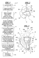
- the receiver 7 and other components 5 are located in the housing shell as shown in Fig. 3 and discussed hereafter.
- the receiver emits sound into the ear of the patient via a receiver tube 7A which runs from a receiver spout 7B of the receiver 7 where sound exits the receiver 7, and runs from there to a receiver hole 6, which is a hole on the shell 8 close to an end 18A of the vent 18 at an innermost end of the housing shell near the ear drum as shown in Fig. 3 .
- a flow chart 9 is provided for the automatic creation of an optimized venting channel (vent) in the hearing instrument by use of software run in a computer.
- first block 10 LOAD WORK ORDER, an order entry is received from a customer. A physical impression of a patient's ear canal is converted to a so-called "point cloud", which is a computer image data file of points on an outside surface of the physical impression. This point cloud data file is then loaded into the computer at block 10.
- a surface file is created by use of a plurality of triangles defined by adjacent point cloud triplets.
- This surface file describes a continuous outer surface of a starter version of the housing shell 8 (see Figs. 2, 3 ). Unnecessary material is removed from the canal area of the end 8A of the shell near the ear canal.
- starter vent 3 which is preferably substantially round in cross-section of relatively small dimensions and runs from the end 8A of the starter shell 8 ( Figs. 2, 3 ) nearest the ear drum to a starter end 8BB lying beyond the outer end 8B of the shell (see Figs. 2, 3 ) where what is known as a faceplate 16 ( Figs. 2, 3 , and 4 ) is to be mounted in a later step.
- This regular round vent 3 is of an initial minimal size and represents a starting point for the software construction (starter vent).
- a shape of an outer end 8B of the shell where the faceplate 16 is to be provided is designed.
- the faceplate 16 glued on the shell will have an edge 16B adjacent to and defining one side of an aperture at an outer end 18B of the vent 18 open to the atmosphere, along with a trap door 19 with a finger-nail lift tab 19A which swings open for access to a battery.
- Other components such as a volume control and a push button, and a microphone opening 20 are mounted on the faceplate.
- the faceplate may contain or have mounted on it also other controls besides the microphone: push buttons, volume control, etc.
- Components including a hybrid, telecoil, reed switch, and an electronics module 5 with battery are provided in a free space 21 (see Fig. 3 ) exterior to the vent 18 defined by vent wall 18C.
- the electronics module may be part of the faceplate or attached directly below it in space 21.
- the receiver 7 is also provided down further inside the housing shell in the free space 21.
- the continuous shell surface is created using the previously mentioned triangulation technique. Material is also removed near the area where the faceplate is to be mounted to provide room for an opening for the vent and components to be mounted on the faceplate.
- vent wall 18C at a central region of the shell is part of a separating wall 18CC separating the vent-as-large-as-possible 18 from the free space 21.
- the receiver tube 7A running from the receiver 7 down to the canal end 8A of the shell near the ear drum lies just outside the separator wall 18CC partially defining the vent-as-large-as possible 18.
- Figs. 2 and 3 show the vent-as-large-as-possible at 18.
- an operator of the software does a cut to create a cut plane 22 identical to a cut currently performed for the known collection vent (regular round vent) previously described.
- the operator does another cut to create another cut plane 23 in order to accommodate the large outlet end 18B of the vent-as-large-as possible 18.
- the faceplate 16 has side edge 16B defining one side of the vent 18 aperture at the end 18B. This is shown in Figs. 2 and 3 .
- FIG. 3 shows the housing shell 8 with the end 8A closest to the ear drum at the bottom and the end 8B at the faceplate 16 at the top after removal of the portion 4 (shown in dashed lines) of the starter shell 8.
- Components of the hearing aid such as the electronics module 5 are shown in this drawing figure in space 21.
- the 45 degree cut plane 22 is provided on curved surface 19 at the housing shell canal side 8A at the bottom.
- the region or free space 21 shows where the electronics module 5 and receiver 7 are to be housed.
- the substantially horizontal rectangle panel illustrated at the top is the faceplate 16. Note that during the shell assembly after the faceplate is glued to the shell all faceplate material 16A outside of the shell is trimmed away.
- the trap door 19 with finger nail protrusion 19A is shown at the top of the faceplate 16.
- the two cut planes 22 and 23 are provided.
- the first cut plane is the 45 degree cut plane 22 described above
- the second cut plane 23 is shown at edge 16B of the faceplate 16 at the left side of the drawing and slanting slightly down from edge 16B. Note that other angles of cuts are also acceptable.
- the vent-as-large-as-possible 18 is defined by the vent wall 18C in Fig. 3 and runs from this second cut plane 23 next to the edge 16B of the faceplate 16 at the outside end 18B of the vent, down to the 45 degree cut plane 22, which is the vent end 18A at the canal side near the eardrum.
- the top cut plane 23 next to the faceplate 16 at edge 16B is called a low angle cut plane.
- the material shown as cross-hatching in Fig. 3 and exterior to the vent wall 18C is either part of the housing shell 8 or the separator wall 18CC.
- cut planes depends upon a location of electronics such as electronics module 5, optional components, receiver 7, receiver hole 6, receiver tube 7A, and values of different preferences parameters that define a shape of the vent 18, vent end 18A and vent end 18B.
- Vent design for the vent-as-large-as-possible of the preferred embodiment is very different from vent design for the previously mentioned prior art collection vent.
- a main difference is that for the collection vent design, an algorithm finds just a biggest contour that can accommodate the vent inlet.
- the vent inlet contour can be smaller than the vent inlet for the collection vent, because one needs to avoid collisions with the components and receiver hole, and adhere to other preferences settings not used for the collection vent.
- Another important difference between the existing prior art vents and the new vent-as-large-as-possible is that prior art vents are built without any consideration of component positions.
- the vent is built first, and then components are placed into the shell in the prior art.
- components such as volume control, push button, receiver, electronics module with battery, and microphone are placed as deep as possible in the starter shell, then the starter shell is cut to remove portions beyond where the faceplate is to be located, and then the starter vent is transformed into the vent-as-large as possible.
- the shape of the vent end at 18A and vent end at 18B in Fig. 3 is defined following preferences settings.
- preferences settings means for the design software of the present preferred embodiment, the particular parameters chosen by the operator defining how different algorithms in the software perform functions.
- Figure 4 shows the housing shell 8 oriented with the ear canal end 8A at the bottom and the faceplate end 8B at the top.
- This drawing figure shows the approximate 45 degree cut plane 22 described previously at the ear canal end 8A and indicates by dashed line 24 with three vertical slashes 50% of the canal width at the vent end 18A to show where the cut plane 22 begins for the approximate 45 degree cut.
- Figures 3 and 4 above show the design steps for the vent-as-large-as-possible wherein respective planar ruled surface cuts (cut planes) are used to maximize vent inlet/outlet areas.
- the software method of the preferred embodiment ensures that the vent-as-large-as-possible takes as much as possible space in the shell adhering to the constraints provided in the requirements (preference settings).
- the software provides the ability to place the vent-as-large-as-possible starter vent (regular round vent) inside the shell in the following manner:
- the software builds the vent-as-large-as-possible similar to a collection IROS (an IROS vent is an lpsolateral Routing of Signal vent):
- Figure 5 shows a view of the vent-as-large-as-possible 18 inside the shell 8 at a cross-section shown in Fig. 3 at section line V-V at a lower part of the shell 8 near the ear canal end 8A.
- the receiver 7 is shown alongside the vent separator wall 18CC in free space 21.
- the software also provides for the following;
Landscapes
- Engineering & Computer Science (AREA)
- Health & Medical Sciences (AREA)
- General Health & Medical Sciences (AREA)
- Neurosurgery (AREA)
- Otolaryngology (AREA)
- Physics & Mathematics (AREA)
- Acoustics & Sound (AREA)
- Signal Processing (AREA)
- Manufacturing & Machinery (AREA)
- Headphones And Earphones (AREA)
- Instructional Devices (AREA)
- Endoscopes (AREA)
Applications Claiming Priority (1)
| Application Number | Priority Date | Filing Date | Title |
|---|---|---|---|
| US12/436,834 US8554352B2 (en) | 2009-05-07 | 2009-05-07 | Method of generating an optimized venting channel in a hearing instrument |
Publications (3)
| Publication Number | Publication Date |
|---|---|
| EP2249585A2 true EP2249585A2 (de) | 2010-11-10 |
| EP2249585A3 EP2249585A3 (de) | 2014-02-26 |
| EP2249585B1 EP2249585B1 (de) | 2017-12-27 |
Family
ID=42635241
Family Applications (1)
| Application Number | Title | Priority Date | Filing Date |
|---|---|---|---|
| EP10161061.6A Not-in-force EP2249585B1 (de) | 2009-05-07 | 2010-04-26 | Verfahren zur Erzeugung eines optimierten Belüftungskanals in einem Hörinstrument |
Country Status (3)
| Country | Link |
|---|---|
| US (1) | US8554352B2 (de) |
| EP (1) | EP2249585B1 (de) |
| DK (1) | DK2249585T3 (de) |
Families Citing this family (6)
| Publication number | Priority date | Publication date | Assignee | Title |
|---|---|---|---|---|
| BR112012008840A2 (pt) * | 2009-10-16 | 2020-09-24 | 3Shape A/S | componentes macios feitos individualmente sob medida |
| WO2011107445A1 (de) * | 2010-03-04 | 2011-09-09 | Bayer Cropscience Ag | Hydrat und wasserfreie kristallform des natriumsalzes des 2-iodo-n-[(4-methoxy-6-methyl-1,3,5-triazin-2-yl)carbamoyl]benzolsulfonamids, verfahren zu deren herstellung, sowie deren verwendung als herbizide und pflanzenwachstumsregulatoren |
| US10129668B2 (en) * | 2013-12-31 | 2018-11-13 | Gn Hearing A/S | Earmold for active occlusion cancellation |
| US9820064B1 (en) * | 2016-06-29 | 2017-11-14 | Daniel R. Schumaier | Method for manufacturing custom in-ear monitor with decorative faceplate |
| US10986432B2 (en) * | 2017-06-30 | 2021-04-20 | Bose Corporation | Customized ear tips |
| EP4002883A1 (de) | 2020-11-23 | 2022-05-25 | Sonova AG | Automatische positionsbestimmung für das gehäuse eines hörgerätes |
Family Cites Families (25)
| Publication number | Priority date | Publication date | Assignee | Title |
|---|---|---|---|---|
| US5487012A (en) * | 1990-12-21 | 1996-01-23 | Topholm & Westermann Aps | Method of preparing an otoplasty or adaptive earpiece individually matched to the shape of an auditory canal |
| US7050876B1 (en) * | 2000-10-06 | 2006-05-23 | Phonak Ltd. | Manufacturing methods and systems for rapid production of hearing-aid shells |
| ES2378060T3 (es) * | 2001-03-02 | 2012-04-04 | 3Shape A/S | Procedimiento para modelar piezas auriculares personalizadas |
| EP1246507A1 (de) * | 2001-03-26 | 2002-10-02 | Widex A/S | Hörgerät mit Abdichtungsring |
| EP1246506A1 (de) * | 2001-03-26 | 2002-10-02 | Widex A/S | CAD-CAM-System zum Entwurf eines Hörgerätes |
| EP1246505A1 (de) * | 2001-03-26 | 2002-10-02 | Widex A/S | Hörgerät mit einer Frontplatte, die zur Anpassung an die Hörgeräteschale automatisch hergestellt wird |
| US20020196954A1 (en) * | 2001-06-22 | 2002-12-26 | Marxen Christopher J. | Modeling and fabrication of three-dimensional irregular surfaces for hearing instruments |
| US6731997B2 (en) * | 2001-07-26 | 2004-05-04 | Phonak Ag | Method for manufacturing hearing devices |
| US7555356B2 (en) * | 2003-04-03 | 2009-06-30 | Phonak Ag | Method for manufacturing a body-worn electronic device adapted to the shape of an individual's body area |
| US7424122B2 (en) * | 2003-04-03 | 2008-09-09 | Sound Design Technologies, Ltd. | Hearing instrument vent |
| US20050088435A1 (en) * | 2003-10-23 | 2005-04-28 | Z. Jason Geng | Novel 3D ear camera for making custom-fit hearing devices for hearing aids instruments and cell phones |
| JP3866748B2 (ja) * | 2005-02-22 | 2007-01-10 | リオン株式会社 | 防水補聴器 |
| US7447556B2 (en) * | 2006-02-03 | 2008-11-04 | Siemens Audiologische Technik Gmbh | System comprising an automated tool and appertaining method for hearing aid design |
| US7991594B2 (en) * | 2005-09-13 | 2011-08-02 | Siemens Corporation | Method and apparatus for the rigid registration of 3D ear impression shapes with skeletons |
| US7979244B2 (en) * | 2005-09-13 | 2011-07-12 | Siemens Corporation | Method and apparatus for aperture detection of 3D hearing aid shells |
| US8086427B2 (en) * | 2005-09-13 | 2011-12-27 | Siemens Corporation | Method and apparatus for the registration of 3D ear impression models |
| US8135453B2 (en) * | 2005-12-07 | 2012-03-13 | Siemens Corporation | Method and apparatus for ear canal surface modeling using optical coherence tomography imaging |
| US8150542B2 (en) * | 2006-06-14 | 2012-04-03 | Phonak Ag | Positioning and orienting a unit of a hearing device relative to individual's head |
| US7672823B2 (en) * | 2006-09-05 | 2010-03-02 | Siemens Aktiengesellschaft | Computerized method for adherence to physical restriction in the construction of an ITE hearing aid |
| US7609259B2 (en) * | 2006-10-18 | 2009-10-27 | Siemens Audiologische Technik Gmbh | System and method for performing a selective fill for a hearing aid shell |
| US8180085B2 (en) * | 2007-08-27 | 2012-05-15 | Siemens Hearing Instruments, Inc. | Assembly procedure for CIC with floating components |
| US20090097682A1 (en) * | 2007-10-12 | 2009-04-16 | Siemens Hearing Instruments Inc. | Computerized rule based binaural modeling system for the hearing aid design |
| US8065118B2 (en) * | 2007-10-16 | 2011-11-22 | Siemens Hearing Instruments Inc. | Method for anatomically aware automatic faceplate placement for hearing instrument design |
| US8265316B2 (en) * | 2008-03-20 | 2012-09-11 | Siemens Medical Instruments Pte. Ltd. | Hearing aid with enhanced vent |
| US8199952B2 (en) * | 2008-04-01 | 2012-06-12 | Siemens Hearing Instruments, Inc. | Method for adaptive construction of a small CIC hearing instrument |
-
2009
- 2009-05-07 US US12/436,834 patent/US8554352B2/en not_active Expired - Fee Related
-
2010
- 2010-04-26 DK DK10161061.6T patent/DK2249585T3/en active
- 2010-04-26 EP EP10161061.6A patent/EP2249585B1/de not_active Not-in-force
Non-Patent Citations (1)
| Title |
|---|
| None |
Also Published As
| Publication number | Publication date |
|---|---|
| EP2249585A3 (de) | 2014-02-26 |
| DK2249585T3 (en) | 2018-04-16 |
| US8554352B2 (en) | 2013-10-08 |
| EP2249585B1 (de) | 2017-12-27 |
| US20100286964A1 (en) | 2010-11-11 |
Similar Documents
| Publication | Publication Date | Title |
|---|---|---|
| EP2107832B1 (de) | Verfahren zur adaptiven Konstruktion eines kleinen CIC-Hörinstrumentents | |
| EP2249585B1 (de) | Verfahren zur Erzeugung eines optimierten Belüftungskanals in einem Hörinstrument | |
| US8332061B2 (en) | Feature driven rule-based framework for automation of modeling workflows in digital manufacturing | |
| EP2432255B1 (de) | Hörgerät | |
| US20060159298A1 (en) | Hearing instrument | |
| US20020196954A1 (en) | Modeling and fabrication of three-dimensional irregular surfaces for hearing instruments | |
| EP2181551B1 (de) | Verfahren zur anpassung von hörgeräten und entsprechendes hörgerät | |
| US9131324B2 (en) | Optimizing operational control of a hearing prosthesis | |
| EP1356709B1 (de) | Herstellungsverfahren und system zur schnellen erzeugung von hörhilfegerätschale | |
| CN103404173B (zh) | 具有音管的助听器 | |
| US12267637B2 (en) | Dome for hearing aids | |
| EP2377331B1 (de) | Hörgerät-hörkapsel und verfahren zum herstellen einer hörgerät-hörkapsel | |
| WO2004082332A1 (en) | Rapid prototype fabrication of a monolithic hearing instrument housing with an integrally-fabricated faceplate | |
| EP2919486A1 (de) | Verfahren zur herstellung von hörgeräteformstücken | |
| US8065118B2 (en) | Method for anatomically aware automatic faceplate placement for hearing instrument design | |
| EP2083583A1 (de) | Herstellung einer Weichsilikonabdeckung für eine Hörgeräthülle | |
| US9961458B1 (en) | Hearing aid sleeve | |
| DK2048895T3 (en) | Computer-controlled rule-based binaural molding system and method for hearing aid design | |
| JP2020184746A (ja) | ベントを有する聴覚デバイス | |
| US20070223757A1 (en) | Tapered vent for a hearing instrument | |
| US8494814B2 (en) | Methods for inlet and outlet modelling of vent as large as possible for hearing aid devices | |
| EP1558058B1 (de) | Verfahren zur Herstellung eines individuell geformten Hörgeräts oder einer individuell geformten Hörhilfe |
Legal Events
| Date | Code | Title | Description |
|---|---|---|---|
| PUAI | Public reference made under article 153(3) epc to a published international application that has entered the european phase |
Free format text: ORIGINAL CODE: 0009012 |
|
| AK | Designated contracting states |
Kind code of ref document: A2 Designated state(s): AT BE BG CH CY CZ DE DK EE ES FI FR GB GR HR HU IE IS IT LI LT LU LV MC MK MT NL NO PL PT RO SE SI SK SM TR |
|
| AX | Request for extension of the european patent |
Extension state: AL BA ME RS |
|
| PUAL | Search report despatched |
Free format text: ORIGINAL CODE: 0009013 |
|
| AK | Designated contracting states |
Kind code of ref document: A3 Designated state(s): AT BE BG CH CY CZ DE DK EE ES FI FR GB GR HR HU IE IS IT LI LT LU LV MC MK MT NL NO PL PT RO SE SI SK SM TR |
|
| AX | Request for extension of the european patent |
Extension state: AL BA ME RS |
|
| RIC1 | Information provided on ipc code assigned before grant |
Ipc: H04R 25/00 20060101AFI20140121BHEP Ipc: H04R 25/02 20060101ALI20140121BHEP |
|
| 17P | Request for examination filed |
Effective date: 20140805 |
|
| RBV | Designated contracting states (corrected) |
Designated state(s): AT BE BG CH CY CZ DE DK EE ES FI FR GB GR HR HU IE IS IT LI LT LU LV MC MK MT NL NO PL PT RO SE SI SK SM TR |
|
| RAP1 | Party data changed (applicant data changed or rights of an application transferred) |
Owner name: SIVANTOS, INC. |
|
| GRAP | Despatch of communication of intention to grant a patent |
Free format text: ORIGINAL CODE: EPIDOSNIGR1 |
|
| INTG | Intention to grant announced |
Effective date: 20170714 |
|
| GRAS | Grant fee paid |
Free format text: ORIGINAL CODE: EPIDOSNIGR3 |
|
| GRAA | (expected) grant |
Free format text: ORIGINAL CODE: 0009210 |
|
| AK | Designated contracting states |
Kind code of ref document: B1 Designated state(s): AT BE BG CH CY CZ DE DK EE ES FI FR GB GR HR HU IE IS IT LI LT LU LV MC MK MT NL NO PL PT RO SE SI SK SM TR |
|
| REG | Reference to a national code |
Ref country code: GB Ref legal event code: FG4D |
|
| REG | Reference to a national code |
Ref country code: CH Ref legal event code: EP |
|
| REG | Reference to a national code |
Ref country code: AT Ref legal event code: REF Ref document number: 959273 Country of ref document: AT Kind code of ref document: T Effective date: 20180115 |
|
| REG | Reference to a national code |
Ref country code: IE Ref legal event code: FG4D |
|
| REG | Reference to a national code |
Ref country code: CH Ref legal event code: NV Representative=s name: E. BLUM AND CO. AG PATENT- UND MARKENANWAELTE , CH |
|
| REG | Reference to a national code |
Ref country code: DE Ref legal event code: R096 Ref document number: 602010047605 Country of ref document: DE |
|
| REG | Reference to a national code |
Ref country code: DK Ref legal event code: T3 Effective date: 20180410 |
|
| REG | Reference to a national code |
Ref country code: FR Ref legal event code: PLFP Year of fee payment: 9 |
|
| PG25 | Lapsed in a contracting state [announced via postgrant information from national office to epo] |
Ref country code: NO Free format text: LAPSE BECAUSE OF FAILURE TO SUBMIT A TRANSLATION OF THE DESCRIPTION OR TO PAY THE FEE WITHIN THE PRESCRIBED TIME-LIMIT Effective date: 20180327 Ref country code: LT Free format text: LAPSE BECAUSE OF FAILURE TO SUBMIT A TRANSLATION OF THE DESCRIPTION OR TO PAY THE FEE WITHIN THE PRESCRIBED TIME-LIMIT Effective date: 20171227 Ref country code: FI Free format text: LAPSE BECAUSE OF FAILURE TO SUBMIT A TRANSLATION OF THE DESCRIPTION OR TO PAY THE FEE WITHIN THE PRESCRIBED TIME-LIMIT Effective date: 20171227 |
|
| REG | Reference to a national code |
Ref country code: NL Ref legal event code: MP Effective date: 20171227 |
|
| REG | Reference to a national code |
Ref country code: LT Ref legal event code: MG4D |
|
| REG | Reference to a national code |
Ref country code: AT Ref legal event code: MK05 Ref document number: 959273 Country of ref document: AT Kind code of ref document: T Effective date: 20171227 |
|
| PG25 | Lapsed in a contracting state [announced via postgrant information from national office to epo] |
Ref country code: HR Free format text: LAPSE BECAUSE OF FAILURE TO SUBMIT A TRANSLATION OF THE DESCRIPTION OR TO PAY THE FEE WITHIN THE PRESCRIBED TIME-LIMIT Effective date: 20171227 Ref country code: GR Free format text: LAPSE BECAUSE OF FAILURE TO SUBMIT A TRANSLATION OF THE DESCRIPTION OR TO PAY THE FEE WITHIN THE PRESCRIBED TIME-LIMIT Effective date: 20180328 Ref country code: BG Free format text: LAPSE BECAUSE OF FAILURE TO SUBMIT A TRANSLATION OF THE DESCRIPTION OR TO PAY THE FEE WITHIN THE PRESCRIBED TIME-LIMIT Effective date: 20180327 Ref country code: LV Free format text: LAPSE BECAUSE OF FAILURE TO SUBMIT A TRANSLATION OF THE DESCRIPTION OR TO PAY THE FEE WITHIN THE PRESCRIBED TIME-LIMIT Effective date: 20171227 |
|
| PG25 | Lapsed in a contracting state [announced via postgrant information from national office to epo] |
Ref country code: NL Free format text: LAPSE BECAUSE OF FAILURE TO SUBMIT A TRANSLATION OF THE DESCRIPTION OR TO PAY THE FEE WITHIN THE PRESCRIBED TIME-LIMIT Effective date: 20171227 |
|
| PG25 | Lapsed in a contracting state [announced via postgrant information from national office to epo] |
Ref country code: CZ Free format text: LAPSE BECAUSE OF FAILURE TO SUBMIT A TRANSLATION OF THE DESCRIPTION OR TO PAY THE FEE WITHIN THE PRESCRIBED TIME-LIMIT Effective date: 20171227 Ref country code: EE Free format text: LAPSE BECAUSE OF FAILURE TO SUBMIT A TRANSLATION OF THE DESCRIPTION OR TO PAY THE FEE WITHIN THE PRESCRIBED TIME-LIMIT Effective date: 20171227 Ref country code: CY Free format text: LAPSE BECAUSE OF FAILURE TO SUBMIT A TRANSLATION OF THE DESCRIPTION OR TO PAY THE FEE WITHIN THE PRESCRIBED TIME-LIMIT Effective date: 20171227 Ref country code: ES Free format text: LAPSE BECAUSE OF FAILURE TO SUBMIT A TRANSLATION OF THE DESCRIPTION OR TO PAY THE FEE WITHIN THE PRESCRIBED TIME-LIMIT Effective date: 20171227 Ref country code: SK Free format text: LAPSE BECAUSE OF FAILURE TO SUBMIT A TRANSLATION OF THE DESCRIPTION OR TO PAY THE FEE WITHIN THE PRESCRIBED TIME-LIMIT Effective date: 20171227 |
|
| PG25 | Lapsed in a contracting state [announced via postgrant information from national office to epo] |
Ref country code: IT Free format text: LAPSE BECAUSE OF FAILURE TO SUBMIT A TRANSLATION OF THE DESCRIPTION OR TO PAY THE FEE WITHIN THE PRESCRIBED TIME-LIMIT Effective date: 20171227 Ref country code: RO Free format text: LAPSE BECAUSE OF FAILURE TO SUBMIT A TRANSLATION OF THE DESCRIPTION OR TO PAY THE FEE WITHIN THE PRESCRIBED TIME-LIMIT Effective date: 20171227 Ref country code: IS Free format text: LAPSE BECAUSE OF FAILURE TO SUBMIT A TRANSLATION OF THE DESCRIPTION OR TO PAY THE FEE WITHIN THE PRESCRIBED TIME-LIMIT Effective date: 20180427 Ref country code: SM Free format text: LAPSE BECAUSE OF FAILURE TO SUBMIT A TRANSLATION OF THE DESCRIPTION OR TO PAY THE FEE WITHIN THE PRESCRIBED TIME-LIMIT Effective date: 20171227 Ref country code: AT Free format text: LAPSE BECAUSE OF FAILURE TO SUBMIT A TRANSLATION OF THE DESCRIPTION OR TO PAY THE FEE WITHIN THE PRESCRIBED TIME-LIMIT Effective date: 20171227 Ref country code: PL Free format text: LAPSE BECAUSE OF FAILURE TO SUBMIT A TRANSLATION OF THE DESCRIPTION OR TO PAY THE FEE WITHIN THE PRESCRIBED TIME-LIMIT Effective date: 20171227 |
|
| REG | Reference to a national code |
Ref country code: DE Ref legal event code: R097 Ref document number: 602010047605 Country of ref document: DE |
|
| PLBE | No opposition filed within time limit |
Free format text: ORIGINAL CODE: 0009261 |
|
| STAA | Information on the status of an ep patent application or granted ep patent |
Free format text: STATUS: NO OPPOSITION FILED WITHIN TIME LIMIT |
|
| PG25 | Lapsed in a contracting state [announced via postgrant information from national office to epo] |
Ref country code: MC Free format text: LAPSE BECAUSE OF FAILURE TO SUBMIT A TRANSLATION OF THE DESCRIPTION OR TO PAY THE FEE WITHIN THE PRESCRIBED TIME-LIMIT Effective date: 20171227 |
|
| 26N | No opposition filed |
Effective date: 20180928 |
|
| REG | Reference to a national code |
Ref country code: BE Ref legal event code: MM Effective date: 20180430 |
|
| REG | Reference to a national code |
Ref country code: IE Ref legal event code: MM4A |
|
| PG25 | Lapsed in a contracting state [announced via postgrant information from national office to epo] |
Ref country code: LU Free format text: LAPSE BECAUSE OF NON-PAYMENT OF DUE FEES Effective date: 20180426 |
|
| PG25 | Lapsed in a contracting state [announced via postgrant information from national office to epo] |
Ref country code: BE Free format text: LAPSE BECAUSE OF NON-PAYMENT OF DUE FEES Effective date: 20180430 Ref country code: SI Free format text: LAPSE BECAUSE OF FAILURE TO SUBMIT A TRANSLATION OF THE DESCRIPTION OR TO PAY THE FEE WITHIN THE PRESCRIBED TIME-LIMIT Effective date: 20171227 |
|
| PG25 | Lapsed in a contracting state [announced via postgrant information from national office to epo] |
Ref country code: IE Free format text: LAPSE BECAUSE OF NON-PAYMENT OF DUE FEES Effective date: 20180426 |
|
| PGFP | Annual fee paid to national office [announced via postgrant information from national office to epo] |
Ref country code: DK Payment date: 20190425 Year of fee payment: 10 Ref country code: DE Payment date: 20190418 Year of fee payment: 10 |
|
| PGFP | Annual fee paid to national office [announced via postgrant information from national office to epo] |
Ref country code: FR Payment date: 20190423 Year of fee payment: 10 |
|
| PGFP | Annual fee paid to national office [announced via postgrant information from national office to epo] |
Ref country code: CH Payment date: 20190424 Year of fee payment: 10 |
|
| PGFP | Annual fee paid to national office [announced via postgrant information from national office to epo] |
Ref country code: GB Payment date: 20190424 Year of fee payment: 10 |
|
| PG25 | Lapsed in a contracting state [announced via postgrant information from national office to epo] |
Ref country code: MT Free format text: LAPSE BECAUSE OF NON-PAYMENT OF DUE FEES Effective date: 20180426 |
|
| PG25 | Lapsed in a contracting state [announced via postgrant information from national office to epo] |
Ref country code: TR Free format text: LAPSE BECAUSE OF FAILURE TO SUBMIT A TRANSLATION OF THE DESCRIPTION OR TO PAY THE FEE WITHIN THE PRESCRIBED TIME-LIMIT Effective date: 20171227 |
|
| PG25 | Lapsed in a contracting state [announced via postgrant information from national office to epo] |
Ref country code: HU Free format text: LAPSE BECAUSE OF FAILURE TO SUBMIT A TRANSLATION OF THE DESCRIPTION OR TO PAY THE FEE WITHIN THE PRESCRIBED TIME-LIMIT; INVALID AB INITIO Effective date: 20100426 Ref country code: PT Free format text: LAPSE BECAUSE OF FAILURE TO SUBMIT A TRANSLATION OF THE DESCRIPTION OR TO PAY THE FEE WITHIN THE PRESCRIBED TIME-LIMIT Effective date: 20171227 |
|
| PG25 | Lapsed in a contracting state [announced via postgrant information from national office to epo] |
Ref country code: MK Free format text: LAPSE BECAUSE OF NON-PAYMENT OF DUE FEES Effective date: 20171227 Ref country code: SE Free format text: LAPSE BECAUSE OF FAILURE TO SUBMIT A TRANSLATION OF THE DESCRIPTION OR TO PAY THE FEE WITHIN THE PRESCRIBED TIME-LIMIT Effective date: 20171227 |
|
| REG | Reference to a national code |
Ref country code: DE Ref legal event code: R119 Ref document number: 602010047605 Country of ref document: DE |
|
| REG | Reference to a national code |
Ref country code: DK Ref legal event code: EBP Effective date: 20200430 |
|
| REG | Reference to a national code |
Ref country code: CH Ref legal event code: PL |
|
| PG25 | Lapsed in a contracting state [announced via postgrant information from national office to epo] |
Ref country code: CH Free format text: LAPSE BECAUSE OF NON-PAYMENT OF DUE FEES Effective date: 20200430 Ref country code: DE Free format text: LAPSE BECAUSE OF NON-PAYMENT OF DUE FEES Effective date: 20201103 Ref country code: LI Free format text: LAPSE BECAUSE OF NON-PAYMENT OF DUE FEES Effective date: 20200430 Ref country code: FR Free format text: LAPSE BECAUSE OF NON-PAYMENT OF DUE FEES Effective date: 20200430 |
|
| GBPC | Gb: european patent ceased through non-payment of renewal fee |
Effective date: 20200426 |
|
| PG25 | Lapsed in a contracting state [announced via postgrant information from national office to epo] |
Ref country code: GB Free format text: LAPSE BECAUSE OF NON-PAYMENT OF DUE FEES Effective date: 20200426 Ref country code: DK Free format text: LAPSE BECAUSE OF NON-PAYMENT OF DUE FEES Effective date: 20200430 |