EP2249576B1 - Verfahren und Apparat zur Dekodierung von Bewegtbildsignalen - Google Patents
Verfahren und Apparat zur Dekodierung von Bewegtbildsignalen Download PDFInfo
- Publication number
- EP2249576B1 EP2249576B1 EP20100169924 EP10169924A EP2249576B1 EP 2249576 B1 EP2249576 B1 EP 2249576B1 EP 20100169924 EP20100169924 EP 20100169924 EP 10169924 A EP10169924 A EP 10169924A EP 2249576 B1 EP2249576 B1 EP 2249576B1
- Authority
- EP
- European Patent Office
- Prior art keywords
- motion vector
- picture
- block
- coding
- motion
- Prior art date
- Legal status (The legal status is an assumption and is not a legal conclusion. Google has not performed a legal analysis and makes no representation as to the accuracy of the status listed.)
- Expired - Lifetime
Links
- 238000000034 method Methods 0.000 title claims description 97
- 239000013598 vector Substances 0.000 claims abstract description 858
- 238000012545 processing Methods 0.000 abstract description 33
- 230000002123 temporal effect Effects 0.000 description 16
- 238000010586 diagram Methods 0.000 description 12
- 230000009466 transformation Effects 0.000 description 9
- 238000004458 analytical method Methods 0.000 description 7
- 238000004364 calculation method Methods 0.000 description 7
- 230000006835 compression Effects 0.000 description 6
- 238000007906 compression Methods 0.000 description 6
- 238000004891 communication Methods 0.000 description 5
- 238000001228 spectrum Methods 0.000 description 5
- 238000006243 chemical reaction Methods 0.000 description 4
- 230000005540 biological transmission Effects 0.000 description 3
- 239000000284 extract Substances 0.000 description 3
- 230000006870 function Effects 0.000 description 2
- 239000004973 liquid crystal related substance Substances 0.000 description 2
- 238000013139 quantization Methods 0.000 description 2
- 230000001360 synchronised effect Effects 0.000 description 2
- 102220526841 Basic salivary proline-rich protein 1_H26L_mutation Human genes 0.000 description 1
- 238000011161 development Methods 0.000 description 1
- 230000000694 effects Effects 0.000 description 1
- 238000005516 engineering process Methods 0.000 description 1
- 230000007774 longterm Effects 0.000 description 1
- 238000010295 mobile communication Methods 0.000 description 1
- 230000003287 optical effect Effects 0.000 description 1
- 238000012360 testing method Methods 0.000 description 1
Images


Classifications
-
- H—ELECTRICITY
- H04—ELECTRIC COMMUNICATION TECHNIQUE
- H04N—PICTORIAL COMMUNICATION, e.g. TELEVISION
- H04N19/00—Methods or arrangements for coding, decoding, compressing or decompressing digital video signals
- H04N19/50—Methods or arrangements for coding, decoding, compressing or decompressing digital video signals using predictive coding
- H04N19/503—Methods or arrangements for coding, decoding, compressing or decompressing digital video signals using predictive coding involving temporal prediction
- H04N19/51—Motion estimation or motion compensation
- H04N19/513—Processing of motion vectors
- H04N19/517—Processing of motion vectors by encoding
- H04N19/52—Processing of motion vectors by encoding by predictive encoding
-
- A—HUMAN NECESSITIES
- A61—MEDICAL OR VETERINARY SCIENCE; HYGIENE
- A61B—DIAGNOSIS; SURGERY; IDENTIFICATION
- A61B5/00—Measuring for diagnostic purposes; Identification of persons
- A61B5/02—Detecting, measuring or recording pulse, heart rate, blood pressure or blood flow; Combined pulse/heart-rate/blood pressure determination; Evaluating a cardiovascular condition not otherwise provided for, e.g. using combinations of techniques provided for in this group with electrocardiography or electroauscultation; Heart catheters for measuring blood pressure
- A61B5/021—Measuring pressure in heart or blood vessels
- A61B5/022—Measuring pressure in heart or blood vessels by applying pressure to close blood vessels, e.g. against the skin; Ophthalmodynamometers
-
- A—HUMAN NECESSITIES
- A61—MEDICAL OR VETERINARY SCIENCE; HYGIENE
- A61B—DIAGNOSIS; SURGERY; IDENTIFICATION
- A61B5/00—Measuring for diagnostic purposes; Identification of persons
- A61B5/02—Detecting, measuring or recording pulse, heart rate, blood pressure or blood flow; Combined pulse/heart-rate/blood pressure determination; Evaluating a cardiovascular condition not otherwise provided for, e.g. using combinations of techniques provided for in this group with electrocardiography or electroauscultation; Heart catheters for measuring blood pressure
- A61B5/026—Measuring blood flow
- A61B5/0261—Measuring blood flow using optical means, e.g. infrared light
-
- A—HUMAN NECESSITIES
- A61—MEDICAL OR VETERINARY SCIENCE; HYGIENE
- A61B—DIAGNOSIS; SURGERY; IDENTIFICATION
- A61B5/00—Measuring for diagnostic purposes; Identification of persons
- A61B5/72—Signal processing specially adapted for physiological signals or for diagnostic purposes
- A61B5/7203—Signal processing specially adapted for physiological signals or for diagnostic purposes for noise prevention, reduction or removal
- A61B5/7207—Signal processing specially adapted for physiological signals or for diagnostic purposes for noise prevention, reduction or removal of noise induced by motion artifacts
-
- H—ELECTRICITY
- H04—ELECTRIC COMMUNICATION TECHNIQUE
- H04N—PICTORIAL COMMUNICATION, e.g. TELEVISION
- H04N19/00—Methods or arrangements for coding, decoding, compressing or decompressing digital video signals
- H04N19/10—Methods or arrangements for coding, decoding, compressing or decompressing digital video signals using adaptive coding
- H04N19/134—Methods or arrangements for coding, decoding, compressing or decompressing digital video signals using adaptive coding characterised by the element, parameter or criterion affecting or controlling the adaptive coding
- H04N19/136—Incoming video signal characteristics or properties
- H04N19/137—Motion inside a coding unit, e.g. average field, frame or block difference
-
- H—ELECTRICITY
- H04—ELECTRIC COMMUNICATION TECHNIQUE
- H04N—PICTORIAL COMMUNICATION, e.g. TELEVISION
- H04N19/00—Methods or arrangements for coding, decoding, compressing or decompressing digital video signals
- H04N19/10—Methods or arrangements for coding, decoding, compressing or decompressing digital video signals using adaptive coding
- H04N19/169—Methods or arrangements for coding, decoding, compressing or decompressing digital video signals using adaptive coding characterised by the coding unit, i.e. the structural portion or semantic portion of the video signal being the object or the subject of the adaptive coding
- H04N19/184—Methods or arrangements for coding, decoding, compressing or decompressing digital video signals using adaptive coding characterised by the coding unit, i.e. the structural portion or semantic portion of the video signal being the object or the subject of the adaptive coding the unit being bits, e.g. of the compressed video stream
-
- H—ELECTRICITY
- H04—ELECTRIC COMMUNICATION TECHNIQUE
- H04N—PICTORIAL COMMUNICATION, e.g. TELEVISION
- H04N19/00—Methods or arrangements for coding, decoding, compressing or decompressing digital video signals
- H04N19/50—Methods or arrangements for coding, decoding, compressing or decompressing digital video signals using predictive coding
- H04N19/503—Methods or arrangements for coding, decoding, compressing or decompressing digital video signals using predictive coding involving temporal prediction
- H04N19/51—Motion estimation or motion compensation
- H04N19/513—Processing of motion vectors
- H04N19/517—Processing of motion vectors by encoding
-
- H—ELECTRICITY
- H04—ELECTRIC COMMUNICATION TECHNIQUE
- H04N—PICTORIAL COMMUNICATION, e.g. TELEVISION
- H04N19/00—Methods or arrangements for coding, decoding, compressing or decompressing digital video signals
- H04N19/50—Methods or arrangements for coding, decoding, compressing or decompressing digital video signals using predictive coding
- H04N19/503—Methods or arrangements for coding, decoding, compressing or decompressing digital video signals using predictive coding involving temporal prediction
- H04N19/51—Motion estimation or motion compensation
- H04N19/513—Processing of motion vectors
- H04N19/521—Processing of motion vectors for estimating the reliability of the determined motion vectors or motion vector field, e.g. for smoothing the motion vector field or for correcting motion vectors
-
- H—ELECTRICITY
- H04—ELECTRIC COMMUNICATION TECHNIQUE
- H04N—PICTORIAL COMMUNICATION, e.g. TELEVISION
- H04N19/00—Methods or arrangements for coding, decoding, compressing or decompressing digital video signals
- H04N19/50—Methods or arrangements for coding, decoding, compressing or decompressing digital video signals using predictive coding
- H04N19/503—Methods or arrangements for coding, decoding, compressing or decompressing digital video signals using predictive coding involving temporal prediction
- H04N19/51—Motion estimation or motion compensation
- H04N19/533—Motion estimation using multistep search, e.g. 2D-log search or one-at-a-time search [OTS]
-
- H—ELECTRICITY
- H04—ELECTRIC COMMUNICATION TECHNIQUE
- H04N—PICTORIAL COMMUNICATION, e.g. TELEVISION
- H04N19/00—Methods or arrangements for coding, decoding, compressing or decompressing digital video signals
- H04N19/50—Methods or arrangements for coding, decoding, compressing or decompressing digital video signals using predictive coding
- H04N19/503—Methods or arrangements for coding, decoding, compressing or decompressing digital video signals using predictive coding involving temporal prediction
- H04N19/51—Motion estimation or motion compensation
- H04N19/537—Motion estimation other than block-based
-
- H—ELECTRICITY
- H04—ELECTRIC COMMUNICATION TECHNIQUE
- H04N—PICTORIAL COMMUNICATION, e.g. TELEVISION
- H04N19/00—Methods or arrangements for coding, decoding, compressing or decompressing digital video signals
- H04N19/50—Methods or arrangements for coding, decoding, compressing or decompressing digital video signals using predictive coding
- H04N19/503—Methods or arrangements for coding, decoding, compressing or decompressing digital video signals using predictive coding involving temporal prediction
- H04N19/51—Motion estimation or motion compensation
- H04N19/56—Motion estimation with initialisation of the vector search, e.g. estimating a good candidate to initiate a search
-
- H—ELECTRICITY
- H04—ELECTRIC COMMUNICATION TECHNIQUE
- H04N—PICTORIAL COMMUNICATION, e.g. TELEVISION
- H04N19/00—Methods or arrangements for coding, decoding, compressing or decompressing digital video signals
- H04N19/50—Methods or arrangements for coding, decoding, compressing or decompressing digital video signals using predictive coding
- H04N19/503—Methods or arrangements for coding, decoding, compressing or decompressing digital video signals using predictive coding involving temporal prediction
- H04N19/51—Motion estimation or motion compensation
- H04N19/577—Motion compensation with bidirectional frame interpolation, i.e. using B-pictures
-
- H—ELECTRICITY
- H04—ELECTRIC COMMUNICATION TECHNIQUE
- H04N—PICTORIAL COMMUNICATION, e.g. TELEVISION
- H04N19/00—Methods or arrangements for coding, decoding, compressing or decompressing digital video signals
- H04N19/50—Methods or arrangements for coding, decoding, compressing or decompressing digital video signals using predictive coding
- H04N19/593—Methods or arrangements for coding, decoding, compressing or decompressing digital video signals using predictive coding involving spatial prediction techniques
-
- H—ELECTRICITY
- H04—ELECTRIC COMMUNICATION TECHNIQUE
- H04N—PICTORIAL COMMUNICATION, e.g. TELEVISION
- H04N19/00—Methods or arrangements for coding, decoding, compressing or decompressing digital video signals
- H04N19/60—Methods or arrangements for coding, decoding, compressing or decompressing digital video signals using transform coding
- H04N19/61—Methods or arrangements for coding, decoding, compressing or decompressing digital video signals using transform coding in combination with predictive coding
-
- H—ELECTRICITY
- H04—ELECTRIC COMMUNICATION TECHNIQUE
- H04N—PICTORIAL COMMUNICATION, e.g. TELEVISION
- H04N19/00—Methods or arrangements for coding, decoding, compressing or decompressing digital video signals
- H04N19/10—Methods or arrangements for coding, decoding, compressing or decompressing digital video signals using adaptive coding
- H04N19/102—Methods or arrangements for coding, decoding, compressing or decompressing digital video signals using adaptive coding characterised by the element, parameter or selection affected or controlled by the adaptive coding
- H04N19/103—Selection of coding mode or of prediction mode
- H04N19/105—Selection of the reference unit for prediction within a chosen coding or prediction mode, e.g. adaptive choice of position and number of pixels used for prediction
-
- H—ELECTRICITY
- H04—ELECTRIC COMMUNICATION TECHNIQUE
- H04N—PICTORIAL COMMUNICATION, e.g. TELEVISION
- H04N19/00—Methods or arrangements for coding, decoding, compressing or decompressing digital video signals
- H04N19/10—Methods or arrangements for coding, decoding, compressing or decompressing digital video signals using adaptive coding
- H04N19/134—Methods or arrangements for coding, decoding, compressing or decompressing digital video signals using adaptive coding characterised by the element, parameter or criterion affecting or controlling the adaptive coding
- H04N19/136—Incoming video signal characteristics or properties
- H04N19/137—Motion inside a coding unit, e.g. average field, frame or block difference
- H04N19/139—Analysis of motion vectors, e.g. their magnitude, direction, variance or reliability
-
- H—ELECTRICITY
- H04—ELECTRIC COMMUNICATION TECHNIQUE
- H04N—PICTORIAL COMMUNICATION, e.g. TELEVISION
- H04N19/00—Methods or arrangements for coding, decoding, compressing or decompressing digital video signals
- H04N19/10—Methods or arrangements for coding, decoding, compressing or decompressing digital video signals using adaptive coding
- H04N19/169—Methods or arrangements for coding, decoding, compressing or decompressing digital video signals using adaptive coding characterised by the coding unit, i.e. the structural portion or semantic portion of the video signal being the object or the subject of the adaptive coding
- H04N19/17—Methods or arrangements for coding, decoding, compressing or decompressing digital video signals using adaptive coding characterised by the coding unit, i.e. the structural portion or semantic portion of the video signal being the object or the subject of the adaptive coding the unit being an image region, e.g. an object
- H04N19/172—Methods or arrangements for coding, decoding, compressing or decompressing digital video signals using adaptive coding characterised by the coding unit, i.e. the structural portion or semantic portion of the video signal being the object or the subject of the adaptive coding the unit being an image region, e.g. an object the region being a picture, frame or field
-
- H—ELECTRICITY
- H04—ELECTRIC COMMUNICATION TECHNIQUE
- H04N—PICTORIAL COMMUNICATION, e.g. TELEVISION
- H04N19/00—Methods or arrangements for coding, decoding, compressing or decompressing digital video signals
- H04N19/10—Methods or arrangements for coding, decoding, compressing or decompressing digital video signals using adaptive coding
- H04N19/169—Methods or arrangements for coding, decoding, compressing or decompressing digital video signals using adaptive coding characterised by the coding unit, i.e. the structural portion or semantic portion of the video signal being the object or the subject of the adaptive coding
- H04N19/17—Methods or arrangements for coding, decoding, compressing or decompressing digital video signals using adaptive coding characterised by the coding unit, i.e. the structural portion or semantic portion of the video signal being the object or the subject of the adaptive coding the unit being an image region, e.g. an object
- H04N19/176—Methods or arrangements for coding, decoding, compressing or decompressing digital video signals using adaptive coding characterised by the coding unit, i.e. the structural portion or semantic portion of the video signal being the object or the subject of the adaptive coding the unit being an image region, e.g. an object the region being a block, e.g. a macroblock
Definitions
- the present invention relates to a motion vector coding method and a motion vector decoding method using inter picture prediction coding.
- multimedia In the age of multimedia which integrally handles audio, video and other information, existing information media, i.e., newspapers, magazines, televisions, radios, telephones and other means through which information is conveyed to people, have recently come to be included in the scope of multimedia.
- multimedia refers to something that is represented by associating not only characters, but also graphics, voices, and especially pictures and the like together, but in order to include the aforementioned existing information media in the scope of multimedia, it appears as a prerequisite to represent such information in digital form.
- the amount of information contained in each of the aforementioned information media is 64Kbits or over per second (telephone quality), and 100Mbits or over per second for moving pictures (current television reception quality), and it is not realistic for the aforementioned information media to handle such an enormous amount of information as it is in digital form.
- ISDN Integrated Services Digital Network
- MPEG Motion Picture Experts Group
- MPEG-1 is a standard for compressing television signal information approximately into one hundredth so that moving picture signals can be transmitted at a rate of 1.5Mbps.
- transmission speed within the scope of the MPEG-1 standard is limited primarily to about 1.5Mbps
- MPEG-2 which was standardized with a view to satisfy requirements for further improved picture quality, allows data transmission of moving picture signals at a rate of 2 ⁇ 15Mbps.
- MPEG-4 which achieves a higher compression ratio than that of MPEG-1 and MPEG-2, allows coding, decoding and operation in an object unit, and realizes a new function required for the multimedia age, has been standardized by the working group (ISO/IEC JTC1/SC29/WG11) which has been engaged in the standardization of MPEG-1 and MPEG-2.
- MPEG-4 was initially aimed at standardization of a coding method for a low bit rate, but now it is extended to standardization of a more versatile coding method for moving pictures further including interlace images and higher bit rates.
- inter picture prediction coding is used as a method of using the temporal redundancies.
- Inter picture prediction coding a picture is coded using a temporarily forward or backward picture as a reference picture.
- the motion (a motion vector) of the current picture to be coded from the reference picture is estimated, and the difference between the picture obtained by the motion compensation and the current picture is calculated. Then, the spatial redundancies are eliminated from this difference, so as to compress the information amount of the moving picture.
- H.26L Test Model Long Term Number 6 (TML-6) draft0) is a description of a reference coding method to be used for the development of a new compression method ITU-T recommendation- H.26L.
- the basic configuration of the algorithm is similar to H.263.
- a picture which is not Inter picture prediction coded, namely, which is intra picture coded is called an I-picture.
- a picture means a single coding unit including both a frame and a field.
- a picture which is inter picture prediction coded with reference to one picture is called a P-picture
- a picture which is inter picture prediction coded with reference to two previously processed pictures is called a B-picture.
- Fig. 1 is a diagram showing a predictive relation between pictures in the above-mentioned moving picture coding method.
- a vertical line indicates one picture, with a picture type (I, P or B) indicated at the lower right thereof.
- Fig. 1 indicates that a picture pointed by an arrow is inter picture prediction coded using a picture located at the other end of the arrowhead as a reference picture. For example, a B-picture which is the second from the left Is coded using the first I-picture and the fourth P-picture as reference pictures.
- a coding mode called direct mode can be selected for coding a B-picture.
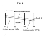
- Fig. 2 is an illustration for explaining the inter picture prediction coding method in direct mode.
- a motion vector MVp of a block X in a reference picture (a picture P4 that is a backward reference picture, in this case) which has been coded immediately before the picture B3 is exploited, where the block X is co-located with the block C.
- the motion vector MVp is a motion vector which was used when the block X was coded, and refers to a picture P1.
- the block C is bi-directionally predicted from the reference pictures, namely, the picture P1 and the picture P4, using motion vectors parallel to the motion vector MVp.
- the motion vectors used for coding the block C are, in this case, a motion vector MVFc for the picture P1 and a motion vector MVBc for the picture P4.
- a difference between a predictive value obtained from motion vectors of neighboring blocks and a motion vector of a current block to be coded is coded for coding the motion vector.
- a "predictive value” indicates a predictive value of a motion vector. Since motion vectors of neighboring blocks have similar direction and motion in many cases, the amount of coding the motion vector can be reduced by coding the difference from the predictive value obtained from the motion vectors of the neighboring blocks.
- Fig. 3 is an illustration for explaining a method for coding a motion vector MV of a current block A to be coded in MPEG-4.
- blocks indicated by a thick line are macroblocks of 16 x 16 pixels, and there exist 4 blocks of 8 x 8 pixels in each macroblock.
- a motion vector is obtained at a level of a block of 8 x 8 pixels.
- a difference between a predictive value and a motion vector MV of the current block A is coded, where the predictive value is calculated from a motion vector MVb of a neighboring block B to the left of the current block A, a motion vector MVc of a neighboring block C just above the current block A and a motion vector MVd of a neighboring block D above and to the right of the current block A.
- a difference between a predictive value and a motion vector MV of the current block A is coded, where the predictive value is calculated from a motion vector MVb of a neighboring block B to the left of the current block A, a motion vector MVc of a neighboring block C just above the current block A and a motion vector MVd of a neighboring block D above and to the right of the current block A.
- a difference between a predictive value and a motion vector MV of the current block A is coded, where the predictive value is calculated from a motion vector MVb of a neighboring block B to the left of the current block A, a motion vector MVc of a neighboring block C just above the current block A and a motion vector MVd of a neighboring block D above and to the right of the current block A.
- a difference between a predictive value and a motion vector MV of the current block A is coded, where the predictive value is calculated from a motion vector MVb of a neighboring block B to the left of the current block A, a motion vector MVc of a neighboring block C above and to the left of the current block A and a motion vector MVd of a neighboring block D just above the current block A.
- the predictive value is calculated using the medians obtained from the horizontal and vertical components of these three motion vectors MVb, MVc and MVd respectively.
- Fig. 4 is an illustration for explaining a method for coding a motion vector MV of a current block A in H.26L.
- a current block A is a block of 4 x 4 pixels, 8 x 8 pixels or 16 x 16 pixels, and a motion vector of this current block A is coded using a motion vector of a neighboring block B including a pixel b located to the left of the current block A, a motion vector of a neighboring block C including a pixel c located just above the current block A and a motion vector of a neighboring block D including a pixel d located above to the right of the current block A.
- the sizes of the neighboring blocks B, C and D are not limited to those as shown in Fig. 4 by dotted lines.
- Fig. 5 is a flowchart showing the procedure of coding the motion vector MV of the current block A using the motion vectors of the neighboring blocks as mentioned above.
- the neighboring block which refers to the picture that the current block A refers to is specified out of the neighboring blocks B, C and D (Step S502), and the number of specified neighboring blocks is determined (Step S504).
- Step S504 When the number of the neighboring blocks determined in Step S504 is 1, the motion vector of that neighboring block which refers to the same picture is considered to be a predictive value of the motion vector MV of the current block A (Step S506).
- Step S505 When the number of the neighboring blocks determined in Step S505 is another value than 1, the motion vector of the neighboring block which refers to another picture than the picture that the current block A refers to, out of the neighboring blocks B, C and D, is considered to be 0 (Step S507). And the median of the motion vectors of the neighboring blocks B, C and D is considered to be a predictive value of the motion vector of the current block A (Step S508).
- Step S510 the difference between the predictive value and the motion vector MV of the current block A is calculated and the difference is coded.
- motion vectors of neighboring blocks are exploited when coding a motion vector of a current block to be coded.
- motion vectors of neighboring blocks are not coded.
- a neighboring block is intra picture coded
- a B-picture is coded in direct mode
- a P-picture is coded in skip mode.
- the neighboring blocks are coded using the motion vectors of other blocks except when they are intra picture coded, namely, the neighboring blocks are coded using their own motion vectors based on the result of motion estimation.
- a motion vector of a current block is coded as follows: When there exists one neighboring block, out of three neighboring blocks, which has no motion vector based on the above result of motion estimation and has been coded using motion vectors of other blocks, the motion vector of that neighboring block is considered to be 0. When there exist two such neighboring blocks, the motion vector of the remaining one neighboring block is used as a predictive value. And when there exist three neighboring blocks, the motion vector is coded considering a predictive value to be 0.
- the present invention is conceived to solve this problem, and the object thereof is to provide a motion vector coding method and a motion vector decoding method for obtaining a more accurate predictive value for higher coding efficiency.
- the motion vector coding method is a motion vector coding method for coding a motion vector of a current block in a moving picture, comprising: a neighboring block specification step of specifying a neighboring block which is located in the neighborhood of the current block and has already been coded; a judgment step of judging whether or not the neighboring block has been coded using a motion vector of another block; a prediction step of deriving a predictive motion vector of the current block using a motion vector calculated from the motion vector of said another block as a motion vector of the neighboring block, when it is judged in the judgment step that the neighboring block has been coded using the motion vector of said another block; and a coding step of coding the motion vector of the current block using the predictive motion vector.
- the motion vector decoding method is a motion vector decoding method for decoding a coded motion vector of a current block in a moving picture, comprising: a neighboring block specification step of specifying a neighboring block which is located in the neighborhood of the current block and has already been decoded, a judgment step of judging whether or not the neighboring block has been coded using a motion vector of another block; a prediction step of deriving a predictive motion vector of the current block using a motion vector calculated from the motion vector of said another block as a motion vector of the neighboring block, when it is judged in the judgment step that the neighboring block has been coded using the motion vector of said another block; and a decoding step of decoding the coded motion vector of the current block using the predictive motion vector.
- the motion vector which has been coded according to the motion vector coding method of the present invention can be properly decoded, and thus the practical value thereof is high.
- the present invention can also be realized as a moving picture coding apparatus and a program using the above-mentioned motion vector coding method, and a storage medium storing the program, and a motion picture decoding apparatus and a program using the above-mentioned motion vector decoding method, and a storage medium storing the program.
- a moving picture coding apparatus in a first embodiment of the present invention will be explained with reference to the figures.
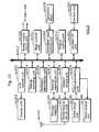
- Fig. 6 is a block diagram of the moving picture coding apparatus in the first embodiment of the present invention.
- This moving picture coding apparatus 100 aims at improving coding efficiency by improving accuracy of a predictive value of a motion vector, and includes a frame memory 101, a difference calculation unit 102, a prediction error coding unit 103, a bit stream generation unit 104, a prediction error decoding unit 105, an addition unit 106, a frame memory 107, a motion vector estimation unit 108, a mode selection unit 109, a coding control unit 110, switches 111 ⁇ 115, a motion vector storage unit 116 and a motion vector coding unit 117.
- the frame memory 101 is a picture memory for holding inputted pictures on a picture-by-picture basis, and reorders the pictures inputted and obtained in order of time into coding order for output.
- the pictures are reordered under the control of the coding control unit 110.
- Fig. 7A shows how the pictures are inputted in the frame memory 101.
- Fig. 7A vertical lines show pictures, and an alphabet and a number at the lower right of each picture indicates a picture type (I, P or B) and a picture number in order of time.
- the pictures inputted to the frame memory 101 are reordered into coding order.
- the pictures are reordered into coding order based on the reference relations in inter picture prediction coding, that is, the pictures are reordered so that the pictures used as reference pictures are coded earlier than the pictures which refer to those reference pictures.
- the reference relations of the pictures P7 ⁇ P13 are shown by arrows in Fig. 7A .
- the arrowheads indicate the pictures which refer to reference pictures, and the other ends of the arrows indicate the reference pictures.
- the pictures shown in Fig. 7A are reordered into those as shown in Fig. 7B .
- Fig. 7B shows the pictures inputted as shown in Fig. 7A and reordered.
- the pictures reordered in the frame memory 101 are read out on a macroblock basis.
- a macroblock is horizontal 16 x vertical 16 pixels in size.
- the difference calculation unit 102 obtains image data of every macroblock from the frame memory 101 via the switch 111, and also obtains a motion compensation image from the mode selection unit 109. Then, the difference calculation unit 102 calculates the difference between the image data and the motion compensation image on a macroblock basis to generate a prediction error image for output.
- the prediction error coding unit 103 performs coding processing including frequency transformation like discrete cosine transformation and quantization on the image data obtained from the frame memory 101 via the switch 112 and the prediction error image obtained by the difference calculation unit 102, so as to create coded data. For example, the frequency transformation and quantization are performed in a unit of horizontal 8 x vertical 8 pixels. Then, the prediction error coding unit 103 outputs the coded data to the bit stream generation unit 104 and the prediction error decoding unit 105.
- the bit stream generation unit 104 performs variable length coding on the coded data outputted from the prediction error coding unit 103, converts the data into that in a bit stream format for output, and further adds information on motion vectors inputted from the motion vector coding unit 117, information on a coding mode inputted from the mode selection unit 109, header information and others, so as to generate a bit stream.
- the prediction error decoding unit 105 inversely quantizes the coded data outputted from the prediction error coding unit 103, and then performs inverse frequency transformation such as inverse discrete cosine transformation so as to decode it into a prediction error image.
- the addition unit 106 adds the motion compensation image to the prediction error image obtained as a result of decoding, and outputs a decoded picture that is image data indicating an image of one picture which has been coded and decoded.
- the frame memory 107 is a picture memory which holds, on a picture-by-picture basis, pictures used as reference pictures when coding other pictures, out of the decoded pictures outputted from the addition unit 106.
- the motion vector estimation unit 108 estimates motion vectors of each block in a current macroblock to be coded, using the decoded pictures accumulated in the frame memory 107 as reference pictures. The estimated motion vectors are outputted to the mode selection unit 109.
- the mode selection unit 109 determines a coding mode of the macroblock using the motion vectors estimated by the motion vector estimation unit 108.
- the coding mode means a method for coding a macroblock.
- the mode selection unit 109 determines a coding mode out of the following: intra picture coding, inter picture prediction coding using motion vectors, and skip mode (inter picture prediction coding in which no motion vector of a current block is coded because prediction coding is performed using a motion vector obtained from motion vectors of other blocks, and no coefficient value is coded because all the coefficient values are 0 as a result of the prediction error coding).
- a coding mode is determined so as to minimize a coding error using a predetermined bit amount.
- the mode selection unit 109 outputs the determined coding mode to the bit stream generation unit 104, and outputs the motion vectors used for that coding mode to the motion vector coding unit 117, respectively.
- the mode selection unit 109 further stores the motion vectors and the coding mode used for that inter picture prediction coding in the motion vector storage unit 116.
- the mode selection unit 109 performs motion compensation based on the determined coding mode and the motion vectors estimated by the motion vector estimation unit 108 so as to create a motion compensation image, and outputs the motion compensation image to the difference calculation unit 102 and the addition unit 106. However, if intra picture coding is selected, no motion compensation image is outputted.
- the mode selection unit 109 further controls the switch 111 and the switch 112 to connect to a terminal "a" and a terminal "c" respectively, and when selecting inter picture prediction coding, it controls the switch 111 and the switch 112 to connect to a terminal "b" and a terminal “d” respectively.
- the above-mentioned motion compensation is performed on a block-by-block basis (8 x 8 pixels in this case).
- the coding control unit 110 determines a picture type (I, P or B) used for coding an inputted picture, and controls the switches 113, 114 and 115 depending on the picture type.
- a picture type is generally determined using a method for allocating a picture type periodically, for example.
- the motion vector storage unit 116 obtains the motion vectors used for inter picture prediction coding and the coding mode from the mode selection unit 109, and stores them.
- the motion vector coding unit 117 codes a motion vector of a current block by the methods as described in Fig. 3 and Fig. 4 . As described above, the motion vector coding unit 117 specifies three neighboring blocks of the current block, determines a predictive value based on the motion vectors of the neighboring blocks, and codes a difference between the predictive value and the motion vector of the current block to be coded.
- the motion vector coding unit 117 in the present embodiment When coding a motion vector of a current block, if a neighboring block is coded using motion vectors of other blocks, such as skip mode and direct mode, the motion vector coding unit 117 in the present embodiment does not consider the motion vector of the neighboring block to be 0 as the conventional art does, but treats a motion vector obtained from the motion vectors of the other blocks as the motion vector of the neighboring block when coding it.
- Fig. 8 is a flowchart showing the general operation of the motion vector coding unit 117 in the present embodiment.
- the motion vector coding unit 117 specifies three previously coded neighboring blocks of a current block (Step S100).
- the motion vector coding unit 117 judges whether each of the specified neighboring blocks is a neighboring block Ba which has been coded using motion vectors of other blocks or a neighboring block Bb which has been coded without using motion vectors of other blocks (Step S102).
- the motion vector coding unit 117 determines whether the specified three neighboring blocks include a neighboring block Ba or not (Step S104).
- Step S104 When it is judged in Step S104 that the neighboring block Ba is included (Y in Step S104), the motion vector coding unit 117 derives a predictive value from the motion vectors of the three neighboring blocks by treating a motion vector obtained from the motion vectors of the other blocks as a motion vector of the neighboring block Ba for coding it, as mentioned above (Step S106).
- Step S104 when it is judged in Step S104 that the neighboring block Ba is not included (N in Step s104), the motion vector coding unit 117 derives a predictive value from motion vectors obtained based on the motion estimation from respective three neighboring blocks Bb and the mode selection (Step S108).
- the motion vector coding unit 117 codes a difference between the motion vector of the current block and the predictive value derived in Steps S106 or S108 (Step S110).
- the motion vector coding unit 117 also outputs the motion vector coded as above to the bit stream generation unit 104.
- the moving picture coding apparatus 100 codes the picture 13 by inter picture prediction coding using another picture as an reference picture.
- the reference picture is a picture P10.
- This picture P10 has been already coded, and the decoded picture thereof is stored in the frame memory 107.
- the coding control unit 110 controls the switches 113, 114 and 115 to be ON. Therefore, macroblocks in the picture P13 which are read out from the frame memory 101 are obtained by the motion vector estimation unit 108, the mode selection unit 109 and the difference calculation unit 102.
- the motion vector estimation unit 108 estimates the motion vector of each block in the macroblock using the decoded picture of the picture P10 stored in the frame memory 107 as a reference picture, and outputs the estimated motion vector to the mode selection unit 109.
- the mode selection unit 109 determines a coding mode of the macroblock in the picture P13 using the motion vector estimated by the motion vector estimation unit 108. Since the picture P13 is a P-picture, the mode selection unit 109 determines, as mentioned above, a coding mode out of the following: intra picture coding, inter picture prediction coding using motion vectors, and skip mode (an inter picture prediction coding in which no motion vector of a current block is coded because prediction coding is performed using a motion vector obtained from motion vectors of other blocks, and no coefficient value is coded because all the coefficient values are 0 as a result of the prediction error coding).
- the motion vector coding unit 117 When the mode selection unit 109 selects inter picture prediction coding using motion vectors, the motion vector coding unit 117 in the present embodiment codes the motion vector of the current block in the picture P13 by the method as explained in Fig. 3 .
- the motion vector coding unit 117 does not consider the motion vector of the neighboring block to be 0, but treats a motion vector obtained from other blocks for coding the neighboring block as a motion vector of that block.
- Fig. 9 is an illustration for explaining how to code a neighboring block C in skip mode.
- a median of a motion vector MVe of a block E, a motion vector MVf of a block F and a motion vector MVg of a block G, which are located in the neighborhood of the neighboring block C, is calculated, and the neighboring block C is coded using a motion vector MVcm indicating the median.
- a median of motion vectors is obtained by calculating medians of horizontal and vertical components of the motion vectors respectively, for example.
- the motion vector coding unit 117 When coding the motion vector of the current block A as shown in Fig. 9 , the motion vector coding unit 117 specifies the three neighboring blocks B, C and D of the current block A (as for the locations of the blocks B, C and D, see Fig. 3 and Fig. 4 ), and judges whether or not each of the neighboring blocks B, C and D is a block which has been coded using motion vectors of other blocks.
- the motion vector coding unit 117 treats the median (a motion vector MVcm) calculated from the motion vectors of the other blocks E, F and G for coding the neighboring block C as a motion vector of the neighboring block C, as mentioned above, and calculates the median of the motion vector MVcm and the motion vectors of the neighboring blocks B and D so as to consider it as a predictive value of the motion vector of the current block A. Then, the motion vector coding unit 117 codes a difference between the predictive value and the motion vector of the current block A.
- the median a motion vector MVcm
- the motion vector storage unit 116 stores coding modes of coded blocks.
- the motion vector coding unit 117 judges whether each of the neighboring blocks B, C and D is a block coded using motion vectors of other blocks or not based on the coding modes stored in the motion vector storage unit 116.
- the motion vector storage unit 116 further stores motion vectors of blocks which have been coded without using motion vectors of other blocks but using their own motion vectors estimated from reference pictures.
- the motion vector storage unit 116 stores the motion vectors MVe, MVf and MVg of the blocks E, F and G, and the motion vector coding unit 117 calculates the above-mentioned motion vector MVcm of the neighboring block C using these motion vectors stored in the motion vector storage unit 116 when coding the motion vector of the current block A.
- a motion vector thereof which is obtained by calculating a median of the motion vectors of the other blocks may be stored in the motion vector storage unit 116 in advance.
- the motion vector coding unit 117 since the motion vector storage unit 116 stores the motion vector MVcm in advance, the motion vector coding unit 117 does not need to calculate the motion vector MVcm of the neighboring block C but can use the motion vector MVcm stored in the motion vector storage unit 116 directly as a motion vector of the neighboring block C, when coding the motion vector of the current block A.
- a prediction error image indicating a difference between a current macroblock in the picture P13 and a motion compensation image is coded by the prediction error coding unit 103 and generated as coded data, and information on the motion vector coded as mentioned above is added to the coded data by the bit stream generation unit 104.
- a difference between a macroblock which has been coded in skip mode and a motion compensation image is 0, and information on the motion vector is not added to the coded data.
- the remaining macroblocks in the picture P13 are coded in the same manner. After completing coding of all the macroblocks in the picture P13, coding of the picture B11 follows.
- the moving picture coding apparatus 100 codes the picture B11 by inter picture prediction coding using two other pictures as reference pictures.
- the reference pictures are the picture P10 located at the forward of the picture B11 and the picture P13 located at the backward of the picture B11. These pictures P10 and P13 have been already coded, and the decoded pictures thereof are stored in the frame memory 107.
- the coding control unit 110 controls the switch 113 to be ON and the switches 114 and 115 to be OFF. Therefore, macroblocks in the picture B11 which are read out from the frame memory 101 are obtained by the motion vector estimation unit 108, the mode selection unit 109 and the difference calculation unit 102.
- the motion vector estimation unit 108 estimates the forward motion vector and the backward motion vector of each block in a macroblock using a decoded picture of the picture P10 stored in the frame memory 107 as a forward reference picture and a decoded picture of the picture P13 as a backward reference picture, and outputs the estimated forward and backward motion vectors to the mode selection unit 109.
- the mode selection unit 109 determines a coding mode of the macroblock in the picture B11 using the forward and backward motion vectors estimated by the motion vector estimation unit 108. Since the picture B11 is a B-picture, the mode selection unit 109 determines a coding mode out of the following: intra picture coding, inter picture prediction coding using forward motion vectors, inter picture prediction coding using backward motion vectors, inter picture prediction coding using bi-directional motion vectors, and direct mode (inter picture prediction coding in which motion compensation is performed using a motion vector obtained from motion vectors of other blocks and no motion vector is coded), for example.
- the motion vector coding unit 117 in the present embodiment codes the motion vectors of the current block in the picture B11 by the method as explained in Fig. 3 .
- the motion vector coding unit 117 codes the motion vectors of the current block in the following manner.
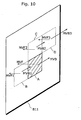
- Fig. 10 is an illustration for explaining inter picture prediction coding using bi-directional motion vectors.
- the motion vector coding unit 117 codes a forward motion vector MVF and a backward motion vector MVB.
- the motion vector coding unit 117 considers a median of forward motion vectors MVF1, MVF2 and MVF3 of the neighboring blocks B, C and D to be a predictive value of the forward motion vector MVF, and codes a difference between the forward motion vector MVF and the predictive value thereof.
- the motion vector coding unit 117 also considers a median of backward motion vectors MVB1, MVB2 and MVB3 of the neighboring blocks B, C and D to be a predictive value of the backward motion vector MVB, and codes a difference between the backward motion vector MVB and the predictive value thereof.
- the median of the motion vectors is obtained by calculating medians of horizontal and vertical components of the motion vectors respectively, for example.
- the motion vector coding unit 117 in the present embodiment When coding motion vectors of a current block in a B-picture, if a neighboring block has been coded in direct mode, the motion vector coding unit 117 in the present embodiment does not consider the motion vectors of the neighboring block to be 0, but considers motion vectors obtained from other blocks as motion vectors of the neighboring block.
- direct modes There are two types of direct modes: temporal direct mode and spatial direct mode.
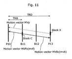
- Fig. 11 is an illustration for explaining how to code the neighboring block in temporal direct mode.
- a motion vector MVp of a block X which is co-located with the neighboring block C, in the picture P13 that is a just previously coded backward reference picture, is used.
- the motion vector MVp is a motion vector used for coding the block X, and is stored in the motion vector storage unit 116.
- This motion vector MVp refers to the picture P10.
- the neighboring block C is coded by bi-directional prediction from the reference pictures, the picture P10 and the picture P13, using motion vectors parallel to the motion vector MVp.
- the motion vectors used for coding the neighboring block C are a motion vector MVFc for the picture P10 and a motion vector MVBc for the picture P13.
- the forward motion vector MVFc is mvf
- the backward motion vector MVBc is mvb
- the motion vector MVp is mvp
- the temporal distance between the backward reference picture (picture P13) for the current picture (picture B11) and the reference picture (picture P10) pointed by the block in the backward reference picture is TRD
- the temporal distance between the current picture (picture B11) and the reference picture (picture P10) pointed by the block in the backward reference picture is TRB
- mvf and mvb are respectively calculated by Equation 1 and Equation 2.
- mvf mvp ⁇ TRB / TRD
- mvb TRB - TRD ⁇ xmvp / TRD
- mvf and mvb respectively represent horizontal components and vertical components of the motion vectors.
- the plus values indicate the direction of the motion vector MVp, and the minus values indicate the direction opposite to that of the motion vector MVp.
- the neighboring block C is coded using the motion vectors MVFc and MVBc obtained as mentioned above.
- the motion vector coding unit 117 When coding the motion vectors MVF and MVB of the current block A as shown in Fig. 10 , the motion vector coding unit 117 specifies the three neighboring blocks B, C and D of the current block A, and judges whether or not each of the neighboring blocks B, C and D is a block which has been coded using a motion vector of another block.
- the motion vector coding unit 117 treats the motion vectors MVFc and MVBc calculated from the motion vector MVp of the block X that is the other block for coding the neighboring block C as motion vectors of the neighboring block C, and calculates the medians of the motion vectors MVFc and MVBc and the motion vectors of the neighboring blocks B and D so as to derive predictive values of the motion vectors of the current block A.
- a forward predictive value and a backward predictive value are derived separately.
- the motion vector coding unit 117 codes differences between the predictive values and the motion vectors MVF and MVB of the current block A, respectively.
- the motion vector storage unit 116 stores coding modes of coded blocks, and based on the coding modes stored in this motion vector storage unit 116, the motion vector coding unit 117 judges whether or not each of the neighboring blocks B, C and D has been coded using motion vectors of other blocks.
- the motion vector storage unit 116 further stores motion vectors of blocks which have been coded without using motion vectors of other blocks but using their own motion vectors estimated from reference pictures.
- the motion vector coding unit 117 uses the motion vectors stored in the motion vector storage unit 116 as they are for the neighboring blocks B and D, but for the neighboring block C, it reads out the motion vector MVp of the block X stored in the motion vector storage unit 116 to calculate the motion vectors MVFc and MVBc.
- the motion vector storage unit 116 may store in advance motion vectors calculated from motion vectors of other blocks in order to code a block which has been coded using the motion vectors of the other blocks. In this case, the motion vector storage unit 116 stores in advance the motion vectors MVFc and MVBc.
- the motion vector coding unit 117 when coding the motion vectors of the current block A, does not need to read out the motion vector MVp of the block X so as to calculate the motion vectors MVFc and MVBc of the neighboring block C using Equation 1 and Equation 2, but can use the motion vectors MVFc and MVBc stored in the motion vector storage unit 116 directly as the motion vectors of the neighboring block C.
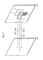
- Fig. 12 is an illustration for explaining how to code a neighboring block in spatial direct mode.
- a neighboring block C of the picture B11 when a neighboring block C of the picture B11 is coded in spatial direct mode, it is coded using motion vectors MVFc and MVBc calculated based on medians in the forward and backward directions respectively which are obtained from the motion vectors MVFe and MVBe of the block E, the motion vectors MVFf and MVBf of the block F and the motion vectors MVFg and MVBg of the block G, where the blocks E, F and G are located in the neighborhood of the neighboring block C.
- the motion vector coding unit 117 When coding the motion vectors MVF and MVB of the current block A as shown in Fig. 10 , the motion vector coding unit 117 specifies the three neighboring blocks B, C and D in the neighborhood of the current block A, and judges whether each of the neighboring blocks B, C and D is a block which has been coded using motion vectors of other blocks or not.
- the motion vector coding unit 117 judges that only the neighboring block C has been coded in spatial direct mode, that is, using motion vectors of other blocks, it treats the motion vectors MVFc and MVBc calculated from the blocks E, F and G which are the other blocks used for coding the neighboring block C as the motion vectors of the neighboring block C, calculates the medians of the motion vectors MVFc and MVBc and the motion vectors of the neighboring blocks B and D, and thus derives predictive values of the motion vectors of the current block A, as shown in Fig. 12 . Then, the motion vector coding unit 117 codes differences between the predictive values and the motion vectors MVF and MVB of the current block A.
- the motion vector storage unit 116 stores motion vectors of blocks which have been coded without using motion vectors of other blocks but using their own motion vectors estimated from reference pictures. In other words, it stores two motion vectors in the forward and backward directions for each of the blocks E, F and G.
- the motion vector coding unit 117 calculates the motion vectors MVFc and MVBc of the neighboring block C using these motion vectors stored in the motion vector storage unit 116.
- the motion vector storage unit 116 may store in advance two motion vectors in the forward and backward directions which are calculated based on medians obtained from motion vectors of other blocks in order to code a block which has been coded using the motion vectors of the other blocks.
- the motion vector storage unit 116 stores in advance the motion vectors MVFc and MVBc. Therefore, when coding the motion vectors of the current block A, the motion vector coding unit 117 does not need to calculate the motion vectors MVFc and MVBc of the neighboring block C, but can use the motion vectors MVFc and MVBc stored in the motion vector storage unit 116 directly as the motion vectors of the neighboring block C.
- the motion vectors of the backward reference picture (the picture P13 in the above case) of the current picture needs to be stored in the motion vector storage unit 116, but when the neighboring block C is coded in spatial direct mode, the storage thereof can be omitted.
- the moving picture coding apparatus 100 when coding motion vectors of a current block, the moving picture coding apparatus 100 performs an exceptional processing if a neighboring block of the current block is not inter picture prediction coded, as mentioned above, but intra picture coded.
- the motion vector coding unit 117 of the moving picture coding apparatus 100 performs processing considering the motion vectors of the block to be 0.
- the motion vector coding unit 117 uses the motion vectors of the remaining one neighboring block as predictive values of motion vectors of a current block. Further, when all the three neighboring blocks have been intra picture coded, the motion vector coding unit 117 performs coding processing of the motion vectors of the current block considering the predictive values thereof to be 0.
- the prediction error image indicating a difference between a current macroblock in the picture B11 and the motion compensation image has been coded by the prediction error coding unit 103 and generated as coded data, and information on the motion vectors which have been coded as mentioned above is added to the coded data by the bit stream generation unit 104.
- information on motion vectors of a macroblock which has been coded in direct mode is not added to the coded data.
- Coding processing of the remaining macroblocks in the picture B11 is performed in the same manner. After the processing is completed for all the macroblocks in the picture B11, the coding processing of the picture B12 follows.
- a motion vector of each current block is coded using a predictive value derived from motion vectors of the previously coded neighboring blocks and the motion vector of the current block. If any of the neighboring blocks has been coded using a motion vector calculated from motion vectors of other blocks, for example, in skip mode or direct mode, a predictive value is derived using, as a motion vector of the neighboring block, the motion vector calculated from the motion vectors of the other blocks for coding that neighboring block.
- a motion vector of a current block is coded using a predictive value derived from a motion vector of a neighboring block
- the motion vector of the neighboring block is not considered as 0 like the conventional art, but the motion vector calculated from the motion vectors of the other blocks is used as the motion vector of the neighboring block.
- accuracy of the above predictive value is improved, and thus efficiency of coding motion vectors can be improved.
- a median calculated from motion vectors of previously coded three neighboring blocks is used as a predictive value for coding a motion vector, but any other number of neighboring blocks than three may be applied, and the predictive value may be determined by any other method.
- a motion vector of an immediately left block may be used as a predictive value, or an average, instead of a median, may be used.
- a median of motion vectors of previously coded three blocks in the neighborhood of the neighboring block is calculated and is treated as a motion vector of the neighboring block, but any other number of blocks than three may be used, and any other method may be used to determine the motion vector.
- a motion vector of an immediately left block may be used as a motion vector of a neighboring block, or an average, instead of a median, may be used.
- a block in a B-picture when a block in a B-picture is coded in spatial direct mode, two motion vectors of the block in the forward and backward directions are calculated, but two motion vectors in the forward direction only or two motion vectors in the backward direction only may be calculated.
- the B-picture refers to two pictures in the forward direction only or two pictures in the backward direction.
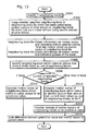
- Fig. 13 is a flowchart showing an operation the motion vector coding unit 117 conducts in deriving a predictive value of a motion vector of a current block to code the motion vector, when reference pictures are selected for every block.
- the motion vector coding unit 117 specifies previously coded three neighboring blocks of a current block (Step S300).
- the motion vector coding unit 117 judges whether each of the specified neighboring blocks is a neighboring block Ba which has been coded using motion vectors of other blocks or a neighboring block Bb which has been coded without using motion vectors of other blocks (Step S302).
- the motion vector coding unit 117 obtains information indicating motion vectors used for coding the block Ba and reference pictures for the neighboring block Ba, and treats those motion vectors used for coding the block Ba as motion vectors thereof.
- the motion vector coding unit 117 obtains information indicating motion vectors of the neighboring block Bb and reference pictures for the neighboring block Bb (Step S304).
- the motion vector coding unit 117 specifies, out of the three neighboring blocks, a neighboring block which refers to the picture that a current block refers to based on the information obtained in Step S304 (Step S306), and determines the number of the specified neighboring blocks (Step S308).
- Step S308 the motion vector coding unit 117 considers the motion vector of the neighboring block which refers to the same picture to be a predictive value of the motion vector MV of the current block (Step S310).
- the motion vector coding unit 117 considers the motion vectors of the neighboring blocks which refer to another picture than the current block refers to, out of the three neighboring blocks, to be 0 (Step S312), and considers a median of the motion vectors of the three neighboring blocks to be a predictive value of the motion vector MV of the current block (Step S314).
- the motion vector coding unit 117 calculates a difference between the predictive value and the motion vector MV of the current block, and codes the difference (Step S316).
- a moving picture decoding apparatus 700 in the second embodiment of the present invention will be explained with reference to the figures.
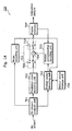
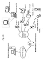
- Fig. 14 is a block diagram showing the structure of the moving picture decoding apparatus 700 in the second embodiment of the present invention.
- the moving picture decoding apparatus 700 as shown in Fig. 14 decodes moving pictures coded by the moving picture coding apparatus 100 in the first embodiment, and includes a bit stream analysis unit 701, a prediction error decoding unit 702, a mode decoding unit 703, a motion compensation decoding unit 705, a motion vector storage unit 706, a frame memory 707, an addition unit 708, switches 709 and 710, and a motion vector decoding unit 711.
- the bit stream analysis unit 701 extracts various data from the inputted bit stream.
- various data includes information on coding mode, information on motion vectors, and so on.
- the extracted coding mode information is outputted to the mode decoding unit 703.
- the extracted motion vector information is outputted to the motion vector decoding unit 711.
- the extracted coded prediction error data is outputted to the prediction error decoding unit 702.
- the prediction error decoding unit 702 decodes the inputted coded prediction error data to generate a prediction error image.
- the generated prediction error image is outputted to the switch 709.
- the switch 709 When the switch 709 is connected to the terminal "b", the prediction error image is outputted to the addition unit 708.
- the mode decoding unit 703 controls the switch 709 and the switch 710 with reference to the coding mode information extracted from the bit stream. If the coding mode is intra picture coding, the mode decoding unit 703 controls the switches 709 and 710 to connect to the terminal "a" and the terminal "c", respectively, and if the coding mode is inter picture coding, it controls the switches 709 and 710 to connect to the terminal "b" and the terminal "d", respectively.
- the mode decoding unit 703 further outputs the coding mode information to the motion vector decoding unit 711.
- the motion vector decoding unit 711 decodes the motion vector information outputted from the bit stream analysis unit 701.
- the motion vector decoding unit 711 derives a predictive value for a current block to be decoded using the motion vectors of previously decoded neighboring blocks, in the same manner as described in Fig. 3 and Fig. 4 .
- the motion vector decoding unit 711 derives a predictive value for a current block A from the motion vector MVb of the neighboring block B, the motion vector MVc of the neighboring block C and the motion vector MVd of the neighboring block D.
- the predictive value is calculated based on a median calculated from each of the horizontal components and vertical components of the three previously decoded motion vectors MVb, MVc and MVd. Then, the motion vector decoding unit 711 adds the predictive value to the difference that is the motion vector information outputted from the bit stream analysis unit 701 so as to determine the motion vector MV of the current block A.
- the motion vector decoding unit 711 determines the motion vector using only the motion vectors of the previously decoded neighboring blocks.
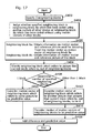
- Fig. 15 is a flowchart showing the general operation of the motion vector decoding unit 711 in the present embodiment.
- the motion vector decoding unit 711 specifies previously decoded three neighboring blocks of a current block to be decoded (Step S200).
- the motion vector decoding unit 711 judges whether each of the specified neighboring blocks is a neighboring block which has been coded using motion vectors of other blocks or a neighboring block Bb which has been coded without using motion vectors of other blocks (Step S202).
- the motion vector decoding unit 711 determines whether or not a neighboring block Ba is included in the specified three neighboring blocks (Step S204).
- the motion vector decoding unit 711 derives a predictive value from the motion vectors of the three neighboring blocks by treating a motion vector calculated from motion vectors of other blocks for decoding the neighboring block Ba as a motion vector of the neighboring block Ba, as mentioned above (Step S206).
- Step S206 when it is judged in Step S206 that a neighboring block Ba is not included (N in Step S204), the motion vector decoding unit 711 derives a predictive value from the motion vectors obtained respectively based on the estimation results of the three neighboring blocks Bb (Step S208).
- the motion vector decoding unit 711 adds the predictive value derived in Step S206 or S208 to the difference that is the motion vector information outputted from the bit stream analysis unit 701, so as to decode the coded motion vector of the current block (Step S210).
- the motion vector decoding unit 711 also outputs the decoded motion vector to the motion compensation decoding unit 705.
- the motion vector storage unit 706 stores the motion vector decoded in the motion vector decoding unit 711 and the coding mode obtained in the mode decoding unit 703.
- the motion compensation decoding unit 705 obtains a motion compensation image of every macroblock from the frame memory 707 based on the motion vector decoded in the motion vector decoding unit 711.
- the addition unit 708 adds the inputted prediction error image and the motion compensation image to generate the decoded image, and outputs the generated decoded image to the frame memory 707.
- the frame memory 707 stores the decoded image generated by the addition unit 708 on every picture basis.
- this moving picture decoding apparatus 700 The operation of this moving picture decoding apparatus 700, particularly the general operation thereof, will be explained first.
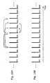
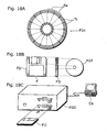
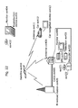
- Fig. 16 is an illustration for explaining input to and output from the moving picture decoding apparatus 700.
- the moving picture decoding apparatus 700 obtains the bit stream outputted from the moving picture coding apparatus 100 in the first embodiment in output order, and decodes the pictures included in the bit stream in sequence. Then, as shown in Fig. 16B , the moving picture decoding apparatus 700 reorders the decoded pictures in display order for output.
- the decoding processing performed by the above moving picture decoding apparatus 700 will be explained below by taking decoding of the picture P13 and the picture B11 as shown in Fig. 16 as a specific example.
- the bit stream analysis unit 701 of the moving picture decoding apparatus 700 obtains the bit stream regarding the picture P13, and extracts the mode selection information and the motion vector information and the coded prediction error data from the bit stream.
- the mode decoding unit 703 controls the switches 709 and 710 with reference to the mode selection information extracted from the bit stream of the picture P13.
- the motion vector decoding unit 711 performs the above decoding processing on the motion vector information extracted from the bit stream of the picture P13 on a block-by-block basis based on the mode selection information indicating inter picture prediction coding outputted from the mode decoding unit 703.
- the motion vector decoding unit 711 when decoding the motion vector of the current block in the picture P13, specifies previously decoded three neighboring blocks of the current block, and judges whether each of these neighboring blocks has been coded using motion vectors of other blocks or not.
- the motion vector decoding unit 711 treats a motion vector calculated from the motion vectors of the other blocks for decoding the neighboring block as a motion vector of the neighboring block, in the same manner as the motion vector coding unit 117 in the first embodiment does.
- the motion vector decoding unit 711 calculates the median of the motion vectors of the previously decoded three blocks in the neighborhood of that neighboring block, and treats it as a motion vector of the neighboring block.
- the motion vector storage unit 706 stores the mode selection information outputted from the mode decoding unit 703, and the motion vector decoding unit 711 judges whether or not each of the neighboring blocks is a block which has been coded using motion vectors of other blocks based on the mode selection information stored in the motion vector storage unit 706.
- the motion vector storage unit 706 further stores the motion vectors of the other blocks used for decoding the neighboring block.
- the motion vector storage unit 706 stores the motion vectors of the three blocks in the neighborhood of the neighboring block which has been coded in skip mode.
- the motion vector decoding unit 711 calculates a median from the motion vectors of the above three blocks stored in the motion vector storage unit 706.
- the motion vector storage unit 706 may store in advance a motion vector of a block which has been coded using motion vectors of other blocks, by calculating a median of the motion vectors for decoding the block. In this case, when decoding the motion vector of the current block, the motion vector decoding unit 711 does not need to obtain the motion vector of the neighboring block which has been coded in skip mode, but can use the motion vector stored in the motion vector storage unit 706 directly as a motion vector of the neighboring block.
- the coded prediction error data of the current macroblock in the picture P13 is decoded in the prediction error decoding unit 702 and generated as a prediction error image, and the switches 709 and 710 are connected to the addition unit 708. Therefore, the motion compensation image generated based on the motion vector decoded in the motion vector decoding unit 711 is added to the prediction error image and outputted to the frame memory 707.
- the motion vector decoding unit 711 stores its motion vector and a coding mode obtained from the mode decoding unit 703 in the motion vector storage unit 706 for decoding the following pictures and blocks.
- the remaining macroblocks in the picture P13 are decoded in sequence. After decoding of all of the macroblocks in the picture P13 is completed, decoding of the picture B11 follows.
- the bit stream analysis unit 701 of the moving picture decoding apparatus 700 obtains the bit stream of the picture B11, and extracts the mode selection information and the motion vector information and the coded prediction error data from the bit stream.
- the mode decoding unit 703 controls the switches 709 and 710 with reference to the mode selection information extracted from the bit stream of the picture B11.
- the motion vector decoding unit 711 performs the above decoding processing on the motion vector information extracted from the bit stream of the picture B11 on a block-by-block basis based on the mode selection information indicating inter picture prediction coding outputted from the mode decoding unit 703.
- the motion vector decoding unit 711 When decoding a motion vector of a current block in the picture B11, the motion vector decoding unit 711 specifies previously decoded three neighboring blocks of the current block, and judges whether or not each of these neighboring blocks has been coded using motion vectors of other blocks. When any of the neighboring blocks is a block which has been coded using motion vectors of other blocks, namely, in temporal or spatial direct mode, the motion vector decoding unit 711 treats a motion vector obtained using the motion vectors of the other blocks for decoding the neighboring block as a motion vector thereof, in the same manner as the motion vector coding unit 117 in the first embodiment does.
- the motion vector decoding unit 711 reads out from the motion vector storage unit 706 a motion vector of a block, which is co-located with a neighboring block which has been coded in direct mode, in a just previously decoded reference picture (picture P13). For example, as shown in Fig. 11 , if the neighboring block C has been coded in temporal direct mode, the motion vector decoding unit 711 reads out the decoded motion vector of the block X in the picture P13 from the motion vector storage unit 706.
- the motion vector decoding unit 711 calculates a forward motion vector MVFc and a backward motion vector MVBc used for coding the neighboring block C using Equation 1 and Equation 2, and uses these motion vectors MVFc and MVBc as motion vectors of the neighboring block C.
- the motion vector decoding unit 711 reads out from the motion vector storage unit 706 the motion vector MVp of the block X in the picture P13 which is co-located with the neighboring block C which has been coded in direct mode.
- the motion vector storage unit 706 may store the motion vector of the block calculated from the motion vectors of the other blocks for decoding the block. In this case, the motion vector storage unit 706 stores the motion vectors MVFc and MVBc in advance.
- the motion vector decoding unit 711 when decoding the motion vector of the current block A, does not need to calculate the motion vectors MVFc and MVBc for the neighboring block C by reading out the motion vector MVp of the block X and using Equation 1 and Equation 2, but can use the motion vectors MVFc and MVBc stored in the motion vector storage unit 706 directly as motion vectors of the neighboring block C.
- the motion vector decoding unit 711 treats motion vectors calculated using motion vectors of other blocks in the neighborhood of the neighboring block as motion vectors thereof. For example, in the situation as shown in Fig. 12 , the motion vector decoding unit 711 calculates medians from the motion vectors of the previously decoded three blocks E, F and G in the neighborhood of the neighboring block C which has been coded in spatial direct mode, and treats the forward motion vector MVFc and the backward motion vector MVBc indicated by the medians as motion vectors of the neighboring block C.
- the motion vector storage unit 706 stores motion vectors used for decoding a block which has been coded without using motion vectors of other blocks. To be more specific, in the situation as shown in Fig. 12 , the motion vector storage unit 706 stores the motion vectors of the three blocks E, F and G in the neighborhood of the neighboring block C which has been coded in spatial direct mode. Therefore, when decoding the motion vector of the current block A, the motion vector decoding unit 711 calculates the motion vectors MVFc and MVBc for the neighboring block from the motion vectors of the above three blocks E, F and G stored in the motion vector storage unit 706.
- the motion vector storage unit 706 may store in advance motion vectors obtained by calculating medians for decoding a block which has been coded using motion vectors of other blocks. In this case, in the situation as shown in Fig. 12 , the motion vector storage unit 706 stores the motion vectors MVFc and MVBc in advance. Therefore, when decoding the motion vectors of the current block A, the motion vector decoding unit 711 does not need to calculate the motion vectors of the neighboring block C which has been coded in spatial direct mode, but can use the motion vectors MVFc and MVBc stored in the motion vector storage unit 706 directly as motion vectors of the neighboring block C.
- the moving picture decoding apparatus 700 performs exceptional processing.
- the motion vector decoding unit 711 of the moving picture decoding apparatus 700 performs processing considering the motion vectors of the neighboring block to be 0.
- the motion vector decoding unit 711 uses the motion vectors of the remaining one neighboring block as predictive values of the motion vectors of the current block. Further, when all the three neighboring blocks have been intra picture coded, the motion vector decoding unit 711 decodes the motion vectors of the current block considering predictive values thereof to be 0.
- the coded prediction error data for the current macroblock in the picture B11 has been decoded in the prediction error decoding unit 702 and generated as a prediction error image, and the switches 709 and 710 are connected to the addition unit 708. Therefore, the motion compensation image generated based on the motion vector decoded by the motion vector decoding unit 711 is added to the prediction error image and outputted to the frame memory 707.
- Decoding processing of the remaining macroblocks in the picture B11 is performed in the same manner. After the processing is completed for all the macroblocks in the picture B11, the decoding processing of the picture B12 follows.
- a predictive value is derived from motion vectors of previously decoded neighboring blocks, and a motion vector of each current block is decoded using the predictive value and the difference. If any of the neighboring blocks has been coded using motion vectors of other blocks, for example, in skip mode or direct mode, a predictive value is derived using, as a motion vector of the neighboring block, a motion vector calculated from the motion vectors of the other blocks for decoding that neighboring block.
- motion vectors which have been coded in the manner as shown in the first embodiment can be decoded properly.
- a median calculated from motion vectors of previously decoded three neighboring blocks is used as a predictive value for decoding a motion vector, but any other number of neighboring blocks than three may be applied, and the predictive value may be determined by any other method.
- a motion vector of an immediately left block may be used as a predictive value, or an average, instead of a median, may be used.
- a motion vector is decoded by adding a predictive value obtained from motion vectors of neighboring blocks and a difference as indicated in a bit stream, but any other method than addition may be used to decode the motion vector.
- a median of motion vectors of previously coded three blocks in the neighborhood of the neighboring block is calculated and is treated as a motion vector of the neighboring block, but any other number of blocks than three may be used, and any other method may be used to determine the motion vector.
- a motion vector of an immediately left block may be used as a motion vector of the neighboring block, or an average, instead of a median, may be used.
- a current B-picture to be decoded refers to two pictures in the forward direction only or two pictures in the backward direction only.
- Fig. 17 is a flowchart showing an operation of the motion vector decoding unit 711 for deriving a predictive value of a motion vector of a current block to be decoded and decoding the motion vector using the predictive value when a reference picture is selected on a block-by-block basis.
- the motion vector decoding unit 711 specifies previously decoded three neighboring blocks of the current block (Step S400).
- the motion vector decoding unit 711 judges whether each of the specified neighboring blocks is a neighboring block Ba which has been coded using motion vectors of other blocks, or a neighboring block Bb which has been coded without using motion vectors of other blocks (Step S402).
- the motion vector decoding unit 711 obtains information indicating a motion vector used for decoding the neighboring block Ba and which reference picture it refers to, and treats the motion vector used for the decoding as a motion vector of the neighboring block Ba.
- the motion vector decoding unit 711 obtains information indicating the motion vector of the neighboring block Bb and which reference picture it refers to (Step S404).
- the motion vector decoding unit 711 specifies the neighboring block which refers to the picture that the current block refers to, out of the three neighboring blocks, based on the information obtained in Step S404 (Step S406), and determines the number of the specified neighboring blocks (Step S408).
- Step S410 the motion vector decoding unit 711 considers the motion vector of that one neighboring block which refers to the same picture to be a predictive value of the motion vector of the current block (Step S410).
- the motion vector decoding unit 711 considers the motion vector of the neighboring block, out of the three neighboring blocks, which refers to another picture than the current block refers to to be 0 (Step S412), and considers the median of the motion vectors of the three neighboring blocks as a predictive value of the motion vector of the current block (Step S414).
- the coded motion vector of the current block is decoded by adding the difference to the predictive value derived in Step S410 or Step S414.
- Fig. 18 is an illustration of a storage medium that stores a program for realizing the motion vector coding method and the motion vector decoding method executed by the moving picture coding apparatus 100 in the first embodiment and the moving picture decoding apparatus 200 in the second embodiment by a computer system.
- Fig. 18B shows the front view and the cross-sectional view of the appearance of a flexible disk FD, and a disk FD1
- Fig. 18A shows an example of a physical format of the disk FD1 as a recording medium itself.
- the disk FD1 is contained in a case F, a plurality of tracks Tr are formed concentrically on the surface of the disk FD1 in the radius direction from the periphery, and each track is divided into 16 sectors Se in the angular direction. Therefore, in the flexible disk storing the above-mentioned program, the motion vector coding method and the motion vector decoding method as the above program are recorded in an area allocated for it on the disk FD1.
- Fig. 18C shows the structure for recording and reproducing the program on and from the flexible disk FD.
- the computer system Cs For recording the program on the flexible disk FD, the computer system Cs writes the motion vector coding method or the motion vector decoding method as the program on the flexible disk FD via a flexible disk drive FDD.
- the program For constructing the above motion vector coding method and the motion vector decoding method in the computer system Cs by the program recorded on the flexible disk FD, the program is read out from the flexible disk FD via the flexible disk drive FDD and transferred to the computer system Cs.
- the above explanation is made on the assumption that a recording medium is a flexible disk FD, but the same processing can also be performed using an optical disk.
- the recording medium is not limited to these, but any other mediums such as an IC card and a ROM cassette can be used in the same manner if a program can be recorded on them.
- Fig. 19 is a block diagram showing the overall configuration of a content providing system ex100 for realizing content distribution service.
- the area for providing communication service is divided into cells of desired size, and base stations exl07 ⁇ ex110 which are fixed wireless stations are placed in respective cells.
- various devices such as a computer ex111, a PDA (personal digital assistant) ex112, a camera ex113, a mobile phone ex114 and a camera-equipped mobile phone ex115 are connected to the Internet ex101, via an Internet service provider ex102, a telephone network ex104 and base stations ex107 ⁇ ex110, for example.
- a computer ex111 a PDA (personal digital assistant) ex112
- a camera ex113 a mobile phone ex114
- a camera-equipped mobile phone ex115 are connected to the Internet ex101, via an Internet service provider ex102, a telephone network ex104 and base stations ex107 ⁇ ex110, for example.
- the content providing system ex100 is not limited to the combination as shown in Fig. 19 , and may be connected to a combination of any of them. Also, each device may be connected directly to the telephone network ex104, not through the base stations ex107 ⁇ ex110 which are the fixed wireless stations.
- the camera ex113 is a device such as a digital video camera capable of shooting moving pictures.
- the mobile phone may be any of a mobile phone of a PDC (Personal Digital Communications) system, a CDMA (Code Division Multiple Access) system, a W-CDMA (Wideband-Code Division Multiple Access) system or a GSM (Global System for Mobile Communications) system, a PHS (Personal Handyphone System) and the like.
- PDC Personal Digital Communications
- CDMA Code Division Multiple Access
- W-CDMA Wideband-Code Division Multiple Access
- GSM Global System for Mobile Communications
- PHS Personal Handyphone System
- a streaming server ex103 is connected to the camera ex113 via the base station ex109 and the telephone network ex104, which enables live distribution or the like using the camera ex113 based on the coded data transmitted from the user.
- Either the camera ex113 or the server for transmitting the data may code the data shot by the camera.
- the moving picture data shot by a camera ex116 may be transmitted to the streaming server ex103 via the computer ex111.
- the camera ex116 is a device such as a digital camera capable of shooting still and moving pictures. In this case, either the camera ex116 or the computer ex111 may code the moving picture data.
- An LSI ex117 included in the computer ex111 or the camera ex116 performs coding processing.
- software for coding and decoding pictures may be integrated into any type of a storage medium (such as a CD-ROM, a flexible disk and a hard disk) that is a recording medium which can be read by the computer ex111 or the like.
- the camera-equipped mobile phone ex115 may transmit the moving picture data. This moving picture data is the data coded by the LSI included in the mobile phone ex115.
- contents (such as a music live video) shot by users using the camera ex113, the camera ex116 or the like are coded in the same manner as the above embodiments and transmitted to the streaming server ex103, while the streaming server ex103 makes stream distribution of the above content data to the clients at their request.
- the clients include the computer ex111, the PDA ex112, the camera ex113, the mobile phone ex114 and so on capable of decoding the above-mentioned coded data.
- the content providing system ex100 is a system in which the clients can thus receive and reproduce the coded data, and further can receive, decode and reproduce the data in real time so as to realize personal broadcasting.
- the moving picture coding apparatus or the moving picture decoding apparatus as shown in each of the above-mentioned embodiments may be used.
- a mobile phone will be explained as an example thereof.
- Fig. 20 is a diagram showing a mobile phone ex115 which uses the motion vector coding method and the motion vector decoding method as explained in the above embodiments.
- the mobile phone ex115 has an antenna ex201 for sending and receiving radio waves between the base station ex110, a camera unit ex203 such as a CCD camera capable of shooting video and still pictures, a display unit ex202 such as a liquid crystal display for displaying the data obtained by decoding video shot by the camera unit ex203, video received by the antenna ex201, or the like, a main body including a set of operation keys ex204, a voice output unit ex208 such as a speaker for outputting voices, a voice input unit ex205 such as a microphone for inputting voices, a storage medium ex207 for storing coded or decoded data, such as data of moving or still pictures shot by the camera, and data of text, moving pictures or still pictures of received e-mails, and a slot unit ex206 for attaching the storage medium ex207 into the mobile phone ex115.
- a camera unit ex203 such
- the storage medium ex207 includes a flash memory element, a kind of EEPROM (Electrically Erasable and Programmable Read Only Memory) that is an electrically erasable and rewritable nonvolatile memory, in a plastic case such as an SD card.
- EEPROM Electrically Erasable and Programmable Read Only Memory
- a main control unit ex311 for overall controlling each unit of the main body including the display unit ex202 and the operation keys ex204 is connected to a power supply circuit unit ex310, an operation input control unit ex304, a picture coding unit ex312, a camera interface unit ex303, an LCD (Liquid Crystal Display) control unit ex302, a picture decoding unit ex309, a multiplex/demultiplex unit ex308, a record/reproduce unit ex307, a modem circuit unit ex306 and a voice processing unit ex305 to each other via a synchronous bus ex313.
- a power supply circuit unit ex310 an operation input control unit ex304
- the power supply circuit unit ex310 supplies respective units with power from a battery pack so as to activate the camera-equipped digital mobile phone ex115 for a ready state.
- the voice processing unit ex305 converts the voice signals received by the voice input unit ex205 in conversation mode into digital voice data
- the modem circuit unit ex306 performs spread spectrum processing of the digital voice data
- the send/receive circuit unit ex301 performs digital-to-analog conversion and frequency transformation of the data, so as to transmit the result via the antenna ex201.
- the data received by the antenna ex201 in conversation mode is amplified and performed of frequency transformation and analog-to-digital conversion
- the modem circuit unit ex306 performs inverse spread spectrum processing of the data
- the voice processing unit ex305 converts it into analog voice data, so as to output the result via the voice output unit ex208.
- the text data of the e-mail inputted by operating the operation keys ex204 on the main body is sent out to the main control unit ex311 via the operation input control unit ex304.
- the modem circuit unit ex306 performs spread spectrum processing of the text data
- the send/receive circuit unit ex301 performs digital-to-analog conversion and frequency transformation of it, the result is transmitted to the base station ex110 via the antenna ex201.
- the picture data shot by the camera unit ex203 is provided to the picture coding unit ex312 via the camera interface unit ex303.
- the picture data shot by the camera unit ex203 can also be displayed directly on the display unit 202 via the camera interface unit ex303 and the LCD control unit ex302.
- the picture coding unit ex312 including the picture coding apparatus explained in the present invention, compress and codes the picture data provided from the camera unit ex203 by the coding method used for the picture coding apparatus as shown in the above-mentioned embodiments so as to transform it into coded picture data, and sends it out to the multiplex/demultiplex unit ex308.
- the mobile phone ex115 sends out the voices received by the voice input unit ex205 during picture pickup by the camera unit ex203 to the multiplex/demultiplex unit ex308 as digital voice data via the voice processing unit ex305.
- the multiplex/demultiplex unit ex308 multiplexes the coded picture data provided from the picture coding unit ex312 and the voice data provided from the voice processing unit ex305 by a predetermined method, the modem circuit unit ex306 performs spread spectrum processing of the resulting multiplexed data, and the send/receive circuit unit ex301 performs digital-to-analog conversion and frequency transformation on the result for transmitting via the antenna ex201.
- the modem circuit unit ex306 performs inverse spread spectrum processing of the data received from the base station ex110 via the antenna ex201, and sends out the resulting multiplexed data to the multiplex/demultiplex unit ex308.
- the multiplex/demultiplex unit ex308 demultiplexes the multiplexed data into a coded bit stream of picture data and a coded bit stream of voice data, and provides the coded picture data to the picture decoding unit ex309 and the voice data to the voice processing unit ex305 respectively via the synchronous bus ex313.
- the picture decoding unit ex309 decodes the coded bit stream of the picture data by the decoding method paired with the coding method as shown in the above-mentioned embodiments, so as to generate reproduced moving picture data, and provides this data to the display unit ex202 via the LCD control unit ex302, and thus moving picture data included in a moving picture file linked to a Website, for instance, is displayed.
- the voice processing unit ex305 converts the voice data into analog voice data, and provides this data to the voice output unit ex208, and thus voice data included in a moving picture file linked to a Website, for instance, is reproduced.
- the present invention is not limited to the above-mentioned system.
- Ground-based or satellite digital broadcasting has been in the news lately, and at least either the picture coding apparatus or the picture decoding apparatus in the above-mentioned embodiments can be incorporated into such a digital broadcasting system as shown in Fig. 22 .
- a coded bit stream of video information is transmitted from a broadcast station ex409 to or communicated with a broadcast satellite ex410 via radio waves.
- the broadcast satellite ex410 Upon receipt of it, the broadcast satellite ex410 transmits radio waves for broadcasting, a home antenna ex406 with a satellite broadcast reception function receives the radio waves, and an apparatus such as a television (receiver) ex401 or a set top box (STB) ex407 decodes the coded bit stream for reproduction.
- the picture decoding apparatus as shown in the above-mentioned embodiments can be implemented in the reproduction device ex403 for reading a coded bit stream recorded on a storage medium ex402 such as a CD and DVD that is a recording medium and decoding it. In this case, the reproduced video signals are displayed on a monitor ex404.
- the picture decoding apparatus in the set top box ex407 connected to a cable ex405 for a cable television or the antenna ex406 for satellite and/or ground-based broadcasting so as to reproduce them on a monitor ex408 of the television.
- the picture decoding apparatus may be incorporated into the television, not in the set top box.
- a car ex412 having an antenna ex411 can receive signals from the satellite ex410, the base station ex107 or the like for reproducing moving pictures on a display apparatus such as a car navigation device ex413 or the like in the car ex412.
- the picture coding apparatus as shown in the above-mentioned embodiments can code picture signals for recording them on a recording medium.
- a recorder ex420 such as a DVD recorder for recording picture signals on a DVD disk ex421 and a disk recorder for recording them on a hard disk. They can also be recorded on an SD card ex422. If the recorder ex420 includes the picture decoding apparatus as shown in the above-mentioned embodiments, the picture signals recorded on the DVD disk ex421 or the SD card ex422 can be reproduced for display on the monitor ex408.
- the structure of the car navigation device ex413 the structure without the camera unit ex203, the camera interface unit ex303 and the picture coding unit ex312, out of the units as shown in Fig. 21 , is conceivable.
- a terminal such as the above-mentioned mobile phone ex114; a sending/receiving terminal equipped with both an encoder and a decoder, a sending terminal equipped with an encoder only, and a receiving terminal equipped with a decoder only.
- the motion vector coding method and the motion vector decoding method according to the present invention are suitable for use in a moving picture coding apparatus for coding moving pictures, a moving picture decoding apparatus for decoding coded moving pictures, and a system including these apparatuses, such as a content providing system for providing contents like digital works, for example, and a digital broadcasting system.
Landscapes
- Engineering & Computer Science (AREA)
- Health & Medical Sciences (AREA)
- Signal Processing (AREA)
- Multimedia (AREA)
- Life Sciences & Earth Sciences (AREA)
- Molecular Biology (AREA)
- Public Health (AREA)
- Physics & Mathematics (AREA)
- Cardiology (AREA)
- Biophysics (AREA)
- Pathology (AREA)
- Biomedical Technology (AREA)
- Heart & Thoracic Surgery (AREA)
- Medical Informatics (AREA)
- Veterinary Medicine (AREA)
- Surgery (AREA)
- Animal Behavior & Ethology (AREA)
- General Health & Medical Sciences (AREA)
- Physiology (AREA)
- Vascular Medicine (AREA)
- Hematology (AREA)
- Ophthalmology & Optometry (AREA)
- Artificial Intelligence (AREA)
- Computer Vision & Pattern Recognition (AREA)
- Psychiatry (AREA)
- Compression Or Coding Systems Of Tv Signals (AREA)
- Compression, Expansion, Code Conversion, And Decoders (AREA)
- Color Television Systems (AREA)
- Error Detection And Correction (AREA)
- Two-Way Televisions, Distribution Of Moving Picture Or The Like (AREA)
- Closed-Circuit Television Systems (AREA)
Claims (2)
- Bildkodiervorrichtung, die einen aktuellen Block in einem Bewegtbild dekodiert, wobei die Vorrichtung umfasst:eine Nachbarblockspezifiziereinheit, die ausgestaltet ist, einen Nachbarblock zu spezifizieren, der in einer Nachbarschaft des aktuellen Blocks angeordnet ist und bereits dekodiert wurde,eine Beurteilungseinheit, die ausgestaltet ist, zu beurteilen, ob der Nachbarblock unter Verwendung eines Bewegungsvektors dekodiert wurde, der von einem Bewegungsvektor eines anderen Blocks berechnet ist, der zeitlich nach dem Nachbarblock angeordnet ist,eine Bestimmungseinheit, die ausgestaltet ist, einen Bewegungsvektor des Nachbarblocks als einen tatsächlichen Bewegungsvektor zu bestimmen, der beim Durchführen von Bewegungskompensation an dem Nachbarblock verwendet wird, wenn die Beurteilungseinheit beurteilt, dass der Nachbarblock unter Verwendung des Bewegungsvektors dekodiert wurde, der von einem Bewegungsvektor des anderen Blocks berechnet wurde,eine Bewegungsvektorprädiktionseinheit (706), die ausgestaltet ist, einen prädiktiven Bewegungsvektor des aktuellen Blocks unter Verwendung mehrerer Bewegungsvektoren von mehreren Nachbarblöcken abzuleiten,eine Bewegungsvektordekodiereinheit (701), die ausgestaltet ist, einen kodierten Bewegungsvektor des aktuellen Blocks zu dekodieren, um einem dekodierten Differenzbewegungsvektor des aktuellen Blocks zu erhalten,eine Bewegungsvektorrückgewinnungseinheit (706), die ausgestaltet ist, einen Bewegungsvektor des aktuellen Blocks durch Addieren des dekodierten Differenzbewegungsvektors des aktuellen Blocks und des prädiktiven Bewegungsvektors zurück zu gewinnen,eine Bewegungskompensationseinheit (705), die ausgestaltet ist, ein bewegungskompensiertes Bild unter Verwendung des zurückgewonnenen Bewegungsvektors und eines Referenzbildes entsprechend dem zurückgewonnenen Bewegungsvektor zu erzeugen,eine Bilddekodiereinheit (702), die ausgestaltet ist, einen Prädiktionsfehler zwischen dem aktuellen Block und dem bewegungskompensierten Bild zu dekodieren, undeine Bildrückgewinnungseinheit (708), die ausgestaltet ist, ein zurückgewonnenes Bild durch Addieren des bewegungskompensierten Bildes und des dekodierten Prädiktionsfehlers zu erhalten,wobei der andere Block ein Block ist, der in einem Bild enthalten ist, das von einem Bild mit dem Nachbarblock unterschiedlich ist, und wobei der tatsächliche Bewegungsvektor des Nachbarblocks aus dem Bewegungsvektor des anderen Blocks berechnet ist.
- Bilddekodierverfahren zum Dekodieren eines aktuellen Blocks in einem Bewegtbild, wobei das Verfahren umfasst:einen Nachbarblockspezifizierschritt (S200, S400) des Spezifizierens eines Nachbarblocks, der in einer Nachbarschaft des aktuellen Blocks angeordnet ist und bereits dekodiert wurde,einen Beurteilungsschritt (S202, S402) des Beurteilens, ob der Nachbarblock unter Verwendung eines Bewegungsvektors dekodiert wurde, der von einem Bewegungsvektor eines anderen Blocks berechnet ist, der zeitlich nach dem Nachbarblock angeordnet ist,einen Bestimmungsschritt des Bestimmens eines Bewegungsvektors des Nachbarblocks als einen tatsächlichen Bewegungsvektor, der beim Durchführen von Bewegungskompensation an dem Nachbarblock verwendet wird, wenn in dem Beurteilungsschritt (S202, S402) beurteilt wurde, dass der Nachbarblock unter Verwendung des Bewegungsvektors dekodiert wurde, der von einem Bewegungsvektor des anderen Blocks berechnet wurde,einen Bewegungsvektorprädiktionsschritt (S206, S410) des Ableitens eines prädiktiven Bewegungsvektors des aktuellen Blocks unter Verwendung mehrerer Bewegungsvektoren von mehreren Nachbarblöcken,einen Bewegungsvektordekodierschritt des Dekodierens eines kodierten Bewegungsvektors des aktuellen Blocks, um einem dekodierten Differenzbewegungsvektor des aktuellen Blocks zu erhalten,einen Bewegungsvektorrückgewinnungsschritt des Zurückgewinnens eines Bewegungsvektors des aktuellen Blocks durch Addieren des dekodierten Differenzbewegungsvektors des aktuellen Blocks und des prädiktiven Bewegungsvektors,einen Bewegungskompensationsschritt des Erzeugens eines bewegungskompensierten Bildes unter Verwendung des zurückgewonnenen Bewegungsvektors und eines Referenzbildes entsprechend dem zurückgewonnenen Bewegungsvektor,einen Bilddekodierschritt des Dedkodierens eines Prädiktionsfehlers zwischen dem aktuellen Block und dem bewegungskompensierten Bild, undeinen Bildrückgewinnungsschritt des Erhaltens eines zurückgewonnenen Bildes durch Addieren des bewegungskompensierten Bildes und des dekodierten Prädiktionsfehlers,wobei der andere Block ein Block ist, der in einem Bild enthalten ist, das von einem Bild mit dem Nachbarblock unterschiedlich ist, und wobei der tatsächliche Bewegungsvektor des Nachbarblocks aus dem Bewegungsvektor des anderen Blocks berechnet ist.
Priority Applications (2)
| Application Number | Priority Date | Filing Date | Title |
|---|---|---|---|
| SI200332318T SI2249576T1 (sl) | 2002-01-09 | 2003-01-08 | Postopek dekodiranja slike in naprava za dekodiranje slike |
| CY20131101127T CY1114867T1 (el) | 2002-01-09 | 2013-12-13 | Μεθοδος αποκωδικοποιησεως εικονας και συσκευη αποκωδικοποιησεως εικονας |
Applications Claiming Priority (4)
| Application Number | Priority Date | Filing Date | Title |
|---|---|---|---|
| JP2002001983 | 2002-01-09 | ||
| JP2002204714 | 2002-07-12 | ||
| JP2002346062A JP4114859B2 (ja) | 2002-01-09 | 2002-11-28 | 動きベクトル符号化方法および動きベクトル復号化方法 |
| EP20030700472 EP1439713B1 (de) | 2002-01-09 | 2003-01-08 | Bewegungsvektorcodierungsverfahren und bewegungsvektordecodierungsverfahren |
Related Parent Applications (1)
| Application Number | Title | Priority Date | Filing Date |
|---|---|---|---|
| EP03700472.8 Division | 2003-01-08 |
Publications (3)
| Publication Number | Publication Date |
|---|---|
| EP2249576A2 EP2249576A2 (de) | 2010-11-10 |
| EP2249576A3 EP2249576A3 (de) | 2011-02-23 |
| EP2249576B1 true EP2249576B1 (de) | 2013-10-16 |
Family
ID=27348065
Family Applications (12)
| Application Number | Title | Priority Date | Filing Date |
|---|---|---|---|
| EP20100187156 Expired - Lifetime EP2273793B1 (de) | 2002-01-09 | 2003-01-08 | Bewegungsvektordecodierungsverfahren |
| EP20100169924 Expired - Lifetime EP2249576B1 (de) | 2002-01-09 | 2003-01-08 | Verfahren und Apparat zur Dekodierung von Bewegtbildsignalen |
| EP20100169922 Expired - Lifetime EP2249570B1 (de) | 2002-01-09 | 2003-01-08 | Vorrichtung Zur Decodierung beweglicher Bilder |
| EP10187151.5A Expired - Lifetime EP2293581B1 (de) | 2002-01-09 | 2003-01-08 | Bewegungsvektordecodierungsverfahren |
| EP20100169913 Expired - Lifetime EP2249573B1 (de) | 2002-01-09 | 2003-01-08 | Bewegungsvektordekodierungsverfahren |
| EP20100169925 Expired - Lifetime EP2249577B1 (de) | 2002-01-09 | 2003-01-08 | Bewegungsvektorcodierungsverfahren |
| EP20030700472 Expired - Lifetime EP1439713B1 (de) | 2002-01-09 | 2003-01-08 | Bewegungsvektorcodierungsverfahren und bewegungsvektordecodierungsverfahren |
| EP20100169919 Expired - Lifetime EP2249574B1 (de) | 2002-01-09 | 2003-01-08 | Vorrichtung zur Codierung beweglicher Bilder |
| EP10187172.1A Expired - Lifetime EP2273795B1 (de) | 2002-01-09 | 2003-01-08 | Bewegungsvektorcodierungsverfahren |
| EP20100169923 Expired - Lifetime EP2249575B1 (de) | 2002-01-09 | 2003-01-08 | Verfahren und Apparat zur Kodierung von Bewegtbildsignalen |
| EP20100169926 Expired - Lifetime EP2249578B1 (de) | 2002-01-09 | 2003-01-08 | Bewegungsvektordecodierungsverfahren |
| EP20100187162 Expired - Lifetime EP2273794B1 (de) | 2002-01-09 | 2003-01-08 | Bewegungsvektorcodierungsverfahren |
Family Applications Before (1)
| Application Number | Title | Priority Date | Filing Date |
|---|---|---|---|
| EP20100187156 Expired - Lifetime EP2273793B1 (de) | 2002-01-09 | 2003-01-08 | Bewegungsvektordecodierungsverfahren |
Family Applications After (10)
| Application Number | Title | Priority Date | Filing Date |
|---|---|---|---|
| EP20100169922 Expired - Lifetime EP2249570B1 (de) | 2002-01-09 | 2003-01-08 | Vorrichtung Zur Decodierung beweglicher Bilder |
| EP10187151.5A Expired - Lifetime EP2293581B1 (de) | 2002-01-09 | 2003-01-08 | Bewegungsvektordecodierungsverfahren |
| EP20100169913 Expired - Lifetime EP2249573B1 (de) | 2002-01-09 | 2003-01-08 | Bewegungsvektordekodierungsverfahren |
| EP20100169925 Expired - Lifetime EP2249577B1 (de) | 2002-01-09 | 2003-01-08 | Bewegungsvektorcodierungsverfahren |
| EP20030700472 Expired - Lifetime EP1439713B1 (de) | 2002-01-09 | 2003-01-08 | Bewegungsvektorcodierungsverfahren und bewegungsvektordecodierungsverfahren |
| EP20100169919 Expired - Lifetime EP2249574B1 (de) | 2002-01-09 | 2003-01-08 | Vorrichtung zur Codierung beweglicher Bilder |
| EP10187172.1A Expired - Lifetime EP2273795B1 (de) | 2002-01-09 | 2003-01-08 | Bewegungsvektorcodierungsverfahren |
| EP20100169923 Expired - Lifetime EP2249575B1 (de) | 2002-01-09 | 2003-01-08 | Verfahren und Apparat zur Kodierung von Bewegtbildsignalen |
| EP20100169926 Expired - Lifetime EP2249578B1 (de) | 2002-01-09 | 2003-01-08 | Bewegungsvektordecodierungsverfahren |
| EP20100187162 Expired - Lifetime EP2273794B1 (de) | 2002-01-09 | 2003-01-08 | Bewegungsvektorcodierungsverfahren |
Country Status (18)
| Country | Link |
|---|---|
| US (22) | US7362807B2 (de) |
| EP (12) | EP2273793B1 (de) |
| JP (1) | JP4114859B2 (de) |
| KR (4) | KR100946848B1 (de) |
| CN (1) | CN1295934C (de) |
| AT (1) | ATE493846T1 (de) |
| AU (1) | AU2003201906B2 (de) |
| BR (2) | BR0302580A (de) |
| CA (3) | CA2438295C (de) |
| CY (5) | CY1114230T1 (de) |
| DE (1) | DE60335516D1 (de) |
| DK (12) | DK1439713T3 (de) |
| ES (11) | ES2408013T3 (de) |
| HU (2) | HUE032083T2 (de) |
| MX (1) | MXPA03007629A (de) |
| PT (11) | PT2293581T (de) |
| SI (5) | SI2249573T1 (de) |
| WO (1) | WO2003061297A1 (de) |
Families Citing this family (91)
| Publication number | Priority date | Publication date | Assignee | Title |
|---|---|---|---|---|
| US6765964B1 (en) | 2000-12-06 | 2004-07-20 | Realnetworks, Inc. | System and method for intracoding video data |
| KR100424762B1 (ko) * | 2001-09-06 | 2004-03-30 | 삼성전자주식회사 | 영상 데이터 제공 시스템 및 방법 |
| US7003035B2 (en) | 2002-01-25 | 2006-02-21 | Microsoft Corporation | Video coding methods and apparatuses |
| US20040001546A1 (en) | 2002-06-03 | 2004-01-01 | Alexandros Tourapis | Spatiotemporal prediction for bidirectionally predictive (B) pictures and motion vector prediction for multi-picture reference motion compensation |
| KR100906473B1 (ko) * | 2002-07-18 | 2009-07-08 | 삼성전자주식회사 | 개선된 움직임 벡터 부호화 및 복호화 방법과 그 장치 |
| US7154952B2 (en) | 2002-07-19 | 2006-12-26 | Microsoft Corporation | Timestamp-independent motion vector prediction for predictive (P) and bidirectionally predictive (B) pictures |
| NO318318B1 (no) * | 2003-06-27 | 2005-02-28 | Tandberg Telecom As | Fremgangsmate for forbedret koding av video |
| US7609763B2 (en) * | 2003-07-18 | 2009-10-27 | Microsoft Corporation | Advanced bi-directional predictive coding of video frames |
| US8064520B2 (en) * | 2003-09-07 | 2011-11-22 | Microsoft Corporation | Advanced bi-directional predictive coding of interlaced video |
| FR2860678A1 (fr) * | 2003-10-01 | 2005-04-08 | Thomson Licensing Sa | Procede de codage differentiel |
| US7480334B2 (en) * | 2003-12-23 | 2009-01-20 | Genesis Microchip Inc. | Temporal motion vector filtering |
| JP3879741B2 (ja) * | 2004-02-25 | 2007-02-14 | ソニー株式会社 | 画像情報符号化装置および画像情報符号化方法 |
| JP5011106B2 (ja) | 2004-07-07 | 2012-08-29 | ダウ グローバル テクノロジーズ エルエルシー | エチレンポリマー組成物を製造するためのマルチステージ方法 |
| US20060012719A1 (en) * | 2004-07-12 | 2006-01-19 | Nokia Corporation | System and method for motion prediction in scalable video coding |
| KR100584603B1 (ko) | 2004-08-03 | 2006-05-30 | 학교법인 대양학원 | 다시점 영상의 다이렉트 모드 움직임 예측 방법 및 장치 |
| KR101104828B1 (ko) * | 2004-12-09 | 2012-01-16 | 삼성전자주식회사 | 움직임 벡터 연산 장치 및 그 방법 |
| US7728909B2 (en) * | 2005-06-13 | 2010-06-01 | Seiko Epson Corporation | Method and system for estimating motion and compensating for perceived motion blur in digital video |
| JP2007028393A (ja) * | 2005-07-20 | 2007-02-01 | Matsushita Electric Ind Co Ltd | 双方向予測符号化ピクチャの直接モードブロックの動きベクトルを求める方法 |
| JP4879558B2 (ja) * | 2005-11-02 | 2012-02-22 | パナソニック株式会社 | 動きベクトル検出装置 |
| US8315308B2 (en) * | 2006-01-11 | 2012-11-20 | Qualcomm Incorporated | Video coding with fine granularity spatial scalability |
| US7644666B2 (en) | 2006-02-09 | 2010-01-12 | Rehrig Pacific Company | Pallet |
| US20070274396A1 (en) * | 2006-05-26 | 2007-11-29 | Ximin Zhang | Complexity adaptive skip mode estimation for video encoding |
| EP2090113A4 (de) * | 2006-11-07 | 2014-08-20 | Samsung Electronics Co Ltd | Verfahren und vorrichtung zur videocodierung und decodierung auf der basis von bewegungsschätzung |
| KR101383540B1 (ko) | 2007-01-03 | 2014-04-09 | 삼성전자주식회사 | 복수의 움직임 벡터 프리딕터들을 사용하여 움직임 벡터를추정하는 방법, 장치, 인코더, 디코더 및 복호화 방법 |
| KR100968204B1 (ko) * | 2007-01-11 | 2010-07-06 | 전자부품연구원 | 다시점 비디오 코덱에서의 영상 예측 방법 및 이를 위한프로그램을 기록한 컴퓨터로 판독 가능한 기록매체 |
| CN101222604B (zh) * | 2007-04-04 | 2010-06-09 | 晨星半导体股份有限公司 | 运算移动估计值与估算图像的移动向量的方法 |
| US20080247466A1 (en) * | 2007-04-09 | 2008-10-09 | Jian Wang | Method and system for skip mode detection |
| CN101682769B (zh) * | 2007-04-12 | 2016-11-09 | 汤姆森特许公司 | 用于视频编码和解码的跳过-直接模式的取决于环境的合并的方法和装置 |
| WO2008153262A1 (en) | 2007-06-15 | 2008-12-18 | Sungkyunkwan University Foundation For Corporate Collaboration | Bi-prediction coding method and apparatus, bi-prediction decoding method and apparatus, and recording midium |
| KR100955396B1 (ko) * | 2007-06-15 | 2010-04-29 | 성균관대학교산학협력단 | 양-예측 부호화 방법 및 장치, 양-예측 복호화 방법 및장치 및 기록매체 |
| US8254455B2 (en) * | 2007-06-30 | 2012-08-28 | Microsoft Corporation | Computing collocated macroblock information for direct mode macroblocks |
| CN100583649C (zh) * | 2007-07-23 | 2010-01-20 | 华为技术有限公司 | 矢量编/解码方法、装置及流媒体播放器 |
| JP2009055519A (ja) * | 2007-08-29 | 2009-03-12 | Sony Corp | 符号化処理装置、符号化処理方法、復号処理装置、及び、復号処理方法 |
| WO2009120984A1 (en) | 2008-03-28 | 2009-10-01 | Kopin Corporation | Handheld wireless display device having high-resolution display suitable for use as a mobile internet device |
| KR101560182B1 (ko) | 2008-01-07 | 2015-10-15 | 삼성전자주식회사 | 다시점 비디오 부호화 방법과 그 장치 및 다시점 비디오 복호화 방법과 그 장치 |
| KR101524465B1 (ko) | 2008-01-10 | 2015-06-02 | 삼성전자주식회사 | 색차 보상을 이용한 다시점 비디오 부호화 방법과 그 장치 및 다시점 비디오 복호화 방법과 그 장치 |
| JP5194833B2 (ja) * | 2008-01-23 | 2013-05-08 | ソニー株式会社 | 符号化装置および方法、記録媒体、並びにプログラム |
| WO2009095962A1 (ja) | 2008-01-29 | 2009-08-06 | Panasonic Corporation | 画像符号化装置、画像符号化方法、画像符号化集積回路および画像符号化プログラム |
| US8165211B2 (en) * | 2008-05-30 | 2012-04-24 | Hong Kong Applied Science and Technology Research Institute Company Limited | Method and apparatus of de-interlacing video |
| US8189666B2 (en) | 2009-02-02 | 2012-05-29 | Microsoft Corporation | Local picture identifier and computation of co-located information |
| TWI405469B (zh) * | 2009-02-20 | 2013-08-11 | Sony Corp | Image processing apparatus and method |
| JP5083248B2 (ja) * | 2009-03-05 | 2012-11-28 | 富士通セミコンダクター株式会社 | 画像データ復号演算装置 |
| US9113168B2 (en) | 2009-05-12 | 2015-08-18 | Lg Electronics Inc. | Method and apparatus of processing a video signal |
| LT3448031T (lt) * | 2009-06-18 | 2021-02-10 | Kabushiki Kaisha Toshiba | Vaizdo dekodavimo aparatas ir dekodavimo būdas |
| US9628794B2 (en) | 2009-06-18 | 2017-04-18 | Kabushiki Kaisha Toshiba | Video encoding apparatus and a video decoding apparatus |
| US8917769B2 (en) * | 2009-07-03 | 2014-12-23 | Intel Corporation | Methods and systems to estimate motion based on reconstructed reference frames at a video decoder |
| US9654792B2 (en) | 2009-07-03 | 2017-05-16 | Intel Corporation | Methods and systems for motion vector derivation at a video decoder |
| US20110002387A1 (en) * | 2009-07-03 | 2011-01-06 | Yi-Jen Chiu | Techniques for motion estimation |
| US8462852B2 (en) * | 2009-10-20 | 2013-06-11 | Intel Corporation | Methods and apparatus for adaptively choosing a search range for motion estimation |
| KR101768207B1 (ko) * | 2010-01-19 | 2017-08-16 | 삼성전자주식회사 | 축소된 예측 움직임 벡터의 후보들에 기초해 움직임 벡터를 부호화, 복호화하는 방법 및 장치 |
| AU2015201666C1 (en) * | 2010-01-19 | 2017-04-27 | Samsung Electronics Co., Ltd. | Method and apparatus for encoding and decoding motion vector based on reduced motion vector predictor candidates |
| CN104967857B (zh) | 2010-01-19 | 2019-08-23 | 三星电子株式会社 | 对图像进行编码/解码的方法和设备 |
| US9794556B2 (en) * | 2010-02-17 | 2017-10-17 | Electronics And Telecommunications Research Institute | Method and device for simplifying encoding and decoding of ultra-high definition images |
| US8354548B2 (en) * | 2010-02-19 | 2013-01-15 | Bristol-Myers Squibb Company | Glycine chroman-6-sulfonamides for use as inhibitors of diacylglycerol lipase |
| CN110460860A (zh) * | 2010-04-01 | 2019-11-15 | 索尼公司 | 图像处理设备和方法 |
| CN105744282B (zh) * | 2010-05-26 | 2018-10-23 | Lg电子株式会社 | 用于处理视频信号的方法和设备 |
| US9300970B2 (en) | 2010-07-09 | 2016-03-29 | Samsung Electronics Co., Ltd. | Methods and apparatuses for encoding and decoding motion vector |
| KR101456499B1 (ko) * | 2010-07-09 | 2014-11-03 | 삼성전자주식회사 | 움직임 벡터의 부호화 방법 및 장치, 그 복호화 방법 및 장치 |
| US10013976B2 (en) | 2010-09-20 | 2018-07-03 | Kopin Corporation | Context sensitive overlays in voice controlled headset computer displays |
| KR101842852B1 (ko) | 2010-09-24 | 2018-03-27 | 선 페이턴트 트러스트 | 화상 부호화 방법, 화상 복호화 방법, 화상 부호화 장치, 및 화상 복호화 장치 |
| SG10201701439WA (en) * | 2010-09-30 | 2017-03-30 | Mitsubishi Electric Corp | Moving image encoding device, moving image decoding device, moving image coding method, and moving image decoding method |
| JP5195875B2 (ja) * | 2010-11-10 | 2013-05-15 | ソニー株式会社 | 復号装置及び方法、記録媒体、並びにプログラム |
| US8711940B2 (en) * | 2010-11-29 | 2014-04-29 | Mediatek Inc. | Method and apparatus of motion vector prediction with extended motion vector predictor |
| EP2654302B1 (de) | 2010-12-13 | 2019-09-04 | Electronics and Telecommunications Research Institute | Procédé de prédiction inter |
| US8666120B2 (en) * | 2010-12-14 | 2014-03-04 | The United States Of America, As Represented By The Secretary Of The Navy | Method and apparatus for conservative motion estimation from multi-image sequences with optimized motion compensation |
| US9547911B2 (en) | 2010-12-14 | 2017-01-17 | The United States Of America, As Represented By The Secretary Of The Navy | Velocity estimation from imagery using symmetric displaced frame difference equation |
| CN102986224B (zh) | 2010-12-21 | 2017-05-24 | 英特尔公司 | 用于增强的解码器侧运动向量导出处理的系统及方法 |
| KR101377528B1 (ko) | 2011-01-15 | 2014-03-27 | 에스케이텔레콤 주식회사 | 움직임 벡터 부호화/복호화 방법 및 장치 |
| WO2012096551A2 (ko) * | 2011-01-15 | 2012-07-19 | 에스케이텔레콤 주식회사 | 움직임 벡터 부호화/복호화 방법 및 장치 |
| WO2012097749A1 (en) * | 2011-01-19 | 2012-07-26 | Mediatek Inc. | Method and apparatus for parsing error robustness of temporal motion vector prediction |
| US9749657B2 (en) | 2011-01-21 | 2017-08-29 | Sharp Kabushiki Kaisha | Buffer compression for motion vector competition |
| EP2675167B1 (de) * | 2011-02-10 | 2018-06-20 | Sun Patent Trust | Verfahren zur kodierung bewegter bilder, vorrichtung zur kodierung bewegter bilder, verfahren zur dekodierung bewegter bilder, vorrichtung zur dekodierung bewegter bilder und vorrichtung zur kodierung/dekodierung bewegter bilder |
| EP3627839B1 (de) * | 2011-03-21 | 2021-10-20 | LG Electronics Inc. | Verfahren zur auswahl von bewegungsvektor-prädiktoren |
| US9648334B2 (en) | 2011-03-21 | 2017-05-09 | Qualcomm Incorporated | Bi-predictive merge mode based on uni-predictive neighbors in video coding |
| WO2012140904A1 (ja) * | 2011-04-15 | 2012-10-18 | パナソニック株式会社 | 画像圧縮装置、画像圧縮方法、集積回路、プログラムおよび映像表示装置 |
| WO2012147344A1 (ja) * | 2011-04-27 | 2012-11-01 | 株式会社Jvcケンウッド | 動画像復号装置、動画像復号方法、及び動画像復号プログラム |
| TWI526056B (zh) | 2011-04-27 | 2016-03-11 | Jvc Kenwood Corp | A moving picture coding apparatus, a motion picture coding method, a motion picture coding program, a transmission apparatus, a transmission method, a transmission program, a video decoding apparatus, a video decoding method, a video decoding program, a reception device, a reception method, Receiving program |
| CN103620527B (zh) | 2011-05-10 | 2018-08-17 | 寇平公司 | 使用动作和语音命令来控制信息显示和远程设备的头戴式计算机 |
| KR101539312B1 (ko) | 2011-05-27 | 2015-07-24 | 미디어텍 인크. | 비디오 프로세싱에 대한 라인 버퍼 감소를 위한 방법 및 장치 |
| KR20130030181A (ko) | 2011-09-16 | 2013-03-26 | 한국전자통신연구원 | 움직임 벡터 예측기를 이용한 움직임 벡터 부호화/복호화 방법 및 장치 |
| US8929954B2 (en) | 2012-04-25 | 2015-01-06 | Kopin Corporation | Headset computer (HSC) as auxiliary display with ASR and HT input |
| CN102946535B (zh) * | 2012-10-09 | 2015-05-13 | 华为技术有限公司 | 预测块的视差矢量预测值获取的方法和装置 |
| KR101676788B1 (ko) * | 2014-10-17 | 2016-11-16 | 삼성전자주식회사 | 멀티코어 시스템 기반 비디오 병렬 복호화 방법 및 그 장치 |
| EP3278558B1 (de) | 2015-03-31 | 2021-07-21 | RealNetworks, Inc. | Bewegungsvektorauswahl und -vorhersage in videocodierungssystemen und verfahren |
| CN105163123B (zh) * | 2015-09-06 | 2018-02-13 | 福州瑞芯微电子股份有限公司 | 一种hevc帧间预测子块mv信息的存取方法和装置 |
| WO2017107072A1 (en) | 2015-12-22 | 2017-06-29 | Realnetworks, Inc. | Motion vector selection and prediction in video coding systems and methods |
| JP6356762B2 (ja) * | 2016-10-31 | 2018-07-11 | 株式会社東芝 | 動画像符号化装置及び方法 |
| US20180184107A1 (en) * | 2016-12-28 | 2018-06-28 | Novatek Microelectronics Corp. | Motion estimation method and motion estimation apparatus |
| SG11202007843YA (en) * | 2018-03-19 | 2020-10-29 | Qualcomm Inc | Improvements to advanced temporal motion vector prediction |
| US10469869B1 (en) * | 2018-06-01 | 2019-11-05 | Tencent America LLC | Method and apparatus for video coding |
| EP3648059B1 (de) * | 2018-10-29 | 2021-02-24 | Axis AB | Videoverarbeitungsvorrichtung und verfahren zum bestimmen von bewegungsmetadaten für ein codiertes video |
Family Cites Families (45)
| Publication number | Priority date | Publication date | Assignee | Title |
|---|---|---|---|---|
| US2002017A (en) * | 1931-03-21 | 1935-05-21 | Bendix Brake Co | Brake |
| FR2644779A1 (fr) * | 1989-03-22 | 1990-09-28 | Centre Nat Rech Scient | Composition ceramique a constante dielectrique elevee |
| ATE148607T1 (de) * | 1991-09-30 | 1997-02-15 | Philips Electronics Nv | Bewegungsvektorschätzung, bewegungsbildkodierung- und -speicherung |
| WO1994022269A1 (en) | 1993-03-24 | 1994-09-29 | Sony Corporation | Method and apparatus for coding/decoding motion vector, and method and apparatus for coding/decoding image signal |
| JPH0730896A (ja) | 1993-06-25 | 1995-01-31 | Matsushita Electric Ind Co Ltd | 動きベクトル符号化及び復号化方法 |
| FR2725577B1 (fr) * | 1994-10-10 | 1996-11-29 | Thomson Consumer Electronics | Procede de codage ou de decodage de vecteurs mouvement et dispositif de codage ou de decodage mettant en oeuvre ledit procede |
| DE69630643T2 (de) | 1995-08-29 | 2004-10-07 | Sharp Kk | Videokodierungsvorrichtung |
| JP2001224036A (ja) * | 1995-10-18 | 2001-08-17 | Sharp Corp | 動画像符号化装置 |
| KR0181069B1 (ko) * | 1995-11-08 | 1999-05-01 | 배순훈 | 움직임 추정장치 |
| JP3344577B2 (ja) * | 1996-09-09 | 2002-11-11 | ソニー株式会社 | 画像符号化装置および画像符号化方法、画像復号化装置および画像復号化方法、並びに記録方法 |
| JP3263807B2 (ja) * | 1996-09-09 | 2002-03-11 | ソニー株式会社 | 画像符号化装置および画像符号化方法 |
| US5991447A (en) * | 1997-03-07 | 1999-11-23 | General Instrument Corporation | Prediction and coding of bi-directionally predicted video object planes for interlaced digital video |
| US6005980A (en) * | 1997-03-07 | 1999-12-21 | General Instrument Corporation | Motion estimation and compensation of video object planes for interlaced digital video |
| TW429636B (en) * | 1998-02-18 | 2001-04-11 | Murata Manufacturing Co | Piezoelectric ceramic composition |
| TW563265B (en) * | 1998-02-18 | 2003-11-21 | Murata Manufacturing Co | Piezoelectric ceramic composition |
| JPH11317961A (ja) | 1998-03-05 | 1999-11-16 | Matsushita Electric Ind Co Ltd | 画像符号化装置及び画像復号化装置,画像符号化方法及び画像復号化方法,並びにデ―タ記憶媒体 |
| KR100328417B1 (ko) * | 1998-03-05 | 2002-03-16 | 마츠시타 덴끼 산교 가부시키가이샤 | 화상부호화장치및화상복호화장치, 화상부보화방법 및 화상복호화방법, 및 데이터기억매체 |
| JP2000099864A (ja) | 1998-09-21 | 2000-04-07 | Yoshitaka Kurita | 介護者支援装置 |
| US6983018B1 (en) * | 1998-11-30 | 2006-01-03 | Microsoft Corporation | Efficient motion vector coding for video compression |
| JP2000299864A (ja) | 1999-04-12 | 2000-10-24 | Canon Inc | 動画像処理方法 |
| JP2000299684A (ja) * | 1999-04-12 | 2000-10-24 | Telecommunication Advancement Organization Of Japan | データ通信システム |
| US7885340B2 (en) * | 1999-04-27 | 2011-02-08 | Realnetworks, Inc. | System and method for generating multiple synchronized encoded representations of media data |
| CN1147159C (zh) * | 1999-04-27 | 2004-04-21 | 三星电子株式会社 | 实时运动图像编码的高速运动估计方法及其装置 |
| EP1056293A1 (de) * | 1999-05-25 | 2000-11-29 | Deutsche Thomson-Brandt Gmbh | Verfahren und Vorrichtung zur Bewegungsschätzung mittels Blockübereinstimmung |
| JP2003513565A (ja) | 1999-10-29 | 2003-04-08 | コーニンクレッカ フィリップス エレクトロニクス エヌ ヴィ | ビデオ符号化方法 |
| US6671319B1 (en) | 1999-12-28 | 2003-12-30 | Sony Corporation | Methods and apparatus for motion estimation using neighboring macroblocks |
| KR100680452B1 (ko) * | 2000-02-22 | 2007-02-08 | 주식회사 팬택앤큐리텔 | 움직임 벡터 메모리의 갱신방법 및 장치 |
| KR100708091B1 (ko) * | 2000-06-13 | 2007-04-16 | 삼성전자주식회사 | 양방향 움직임 벡터를 이용한 프레임 레이트 변환 장치 및그 방법 |
| US8005145B2 (en) * | 2000-08-11 | 2011-08-23 | Nokia Corporation | Method and apparatus for transferring video frame in telecommunication system |
| US6842483B1 (en) * | 2000-09-11 | 2005-01-11 | The Hong Kong University Of Science And Technology | Device, method and digital video encoder for block-matching motion estimation |
| US7327787B1 (en) | 2000-11-20 | 2008-02-05 | Intel Corporation | Method and apparatus for motion estimation |
| WO2002071736A2 (en) | 2001-03-05 | 2002-09-12 | Intervideo, Inc. | Systems and methods of error resilience in a video decoder |
| KR100378795B1 (ko) * | 2001-04-02 | 2003-04-03 | 엘지전자 주식회사 | 동영상에서 b픽쳐의 신축적인 다이렉트 모드 코딩 방법 |
| US8111754B1 (en) * | 2001-07-11 | 2012-02-07 | Dolby Laboratories Licensing Corporation | Interpolation of video compression frames |
| US6980596B2 (en) * | 2001-11-27 | 2005-12-27 | General Instrument Corporation | Macroblock level adaptive frame/field coding for digital video content |
| US7003035B2 (en) * | 2002-01-25 | 2006-02-21 | Microsoft Corporation | Video coding methods and apparatuses |
| JP4130783B2 (ja) * | 2002-04-23 | 2008-08-06 | 松下電器産業株式会社 | 動きベクトル符号化方法および動きベクトル復号化方法 |
| KR100491530B1 (ko) * | 2002-05-03 | 2005-05-27 | 엘지전자 주식회사 | 모션 벡터 결정 방법 |
| US20040001546A1 (en) * | 2002-06-03 | 2004-01-01 | Alexandros Tourapis | Spatiotemporal prediction for bidirectionally predictive (B) pictures and motion vector prediction for multi-picture reference motion compensation |
| KR100774296B1 (ko) * | 2002-07-16 | 2007-11-08 | 삼성전자주식회사 | 움직임 벡터 부호화 방법, 복호화 방법 및 그 장치 |
| US7020200B2 (en) * | 2002-08-13 | 2006-03-28 | Lsi Logic Corporation | System and method for direct motion vector prediction in bi-predictive video frames and fields |
| US7227901B2 (en) * | 2002-11-21 | 2007-06-05 | Ub Video Inc. | Low-complexity deblocking filter |
| US6646578B1 (en) * | 2002-11-22 | 2003-11-11 | Ub Video Inc. | Context adaptive variable length decoding system and method |
| US8085846B2 (en) * | 2004-08-24 | 2011-12-27 | Thomson Licensing | Method and apparatus for decoding hybrid intra-inter coded blocks |
| US20130003843A1 (en) * | 2010-03-12 | 2013-01-03 | Mediatek Singapore Pte. Ltd. | Motion Prediction Method |
-
2002
- 2002-11-28 JP JP2002346062A patent/JP4114859B2/ja not_active Expired - Lifetime
-
2003
- 2003-01-08 DK DK03700472T patent/DK1439713T3/da active
- 2003-01-08 MX MXPA03007629A patent/MXPA03007629A/es active IP Right Grant
- 2003-01-08 AT AT03700472T patent/ATE493846T1/de active
- 2003-01-08 PT PT101871515T patent/PT2293581T/pt unknown
- 2003-01-08 ES ES10169913T patent/ES2408013T3/es not_active Expired - Lifetime
- 2003-01-08 EP EP20100187156 patent/EP2273793B1/de not_active Expired - Lifetime
- 2003-01-08 EP EP20100169924 patent/EP2249576B1/de not_active Expired - Lifetime
- 2003-01-08 ES ES10187151.5T patent/ES2600786T3/es not_active Expired - Lifetime
- 2003-01-08 KR KR1020097022830A patent/KR100946848B1/ko active IP Right Grant
- 2003-01-08 DK DK10169922T patent/DK2249570T3/da active
- 2003-01-08 DK DK10169925T patent/DK2249577T3/da active
- 2003-01-08 PT PT10169926T patent/PT2249578E/pt unknown
- 2003-01-08 DK DK10169913T patent/DK2249573T3/da active
- 2003-01-08 WO PCT/JP2003/000055 patent/WO2003061297A1/ja active Application Filing
- 2003-01-08 SI SI200332251T patent/SI2249573T1/sl unknown
- 2003-01-08 DK DK10169923T patent/DK2249575T3/da active
- 2003-01-08 EP EP20100169922 patent/EP2249570B1/de not_active Expired - Lifetime
- 2003-01-08 PT PT10169923T patent/PT2249575E/pt unknown
- 2003-01-08 EP EP10187151.5A patent/EP2293581B1/de not_active Expired - Lifetime
- 2003-01-08 DK DK10169924T patent/DK2249576T3/da active
- 2003-01-08 DK DK10187151.5T patent/DK2293581T3/en active
- 2003-01-08 ES ES10169926T patent/ES2410533T3/es not_active Expired - Lifetime
- 2003-01-08 AU AU2003201906A patent/AU2003201906B2/en not_active Expired
- 2003-01-08 ES ES10187162T patent/ES2388814T3/es not_active Expired - Lifetime
- 2003-01-08 PT PT10187156T patent/PT2273793E/pt unknown
- 2003-01-08 CA CA2438295A patent/CA2438295C/en not_active Expired - Lifetime
- 2003-01-08 HU HUE10187151A patent/HUE032083T2/en unknown
- 2003-01-08 US US10/468,203 patent/US7362807B2/en active Active
- 2003-01-08 EP EP20100169913 patent/EP2249573B1/de not_active Expired - Lifetime
- 2003-01-08 PT PT10169924T patent/PT2249576E/pt unknown
- 2003-01-08 EP EP20100169925 patent/EP2249577B1/de not_active Expired - Lifetime
- 2003-01-08 SI SI200332318T patent/SI2249576T1/sl unknown
- 2003-01-08 KR KR1020077026287A patent/KR100946846B1/ko active IP Right Grant
- 2003-01-08 KR KR1020037011000A patent/KR100923379B1/ko active IP Right Grant
- 2003-01-08 DK DK10169919T patent/DK2249574T3/da active
- 2003-01-08 ES ES10187172.1T patent/ES2600520T3/es not_active Expired - Lifetime
- 2003-01-08 DK DK10187156T patent/DK2273793T3/da active
- 2003-01-08 PT PT101699130T patent/PT2249573E/pt unknown
- 2003-01-08 PT PT03700472T patent/PT1439713E/pt unknown
- 2003-01-08 EP EP20030700472 patent/EP1439713B1/de not_active Expired - Lifetime
- 2003-01-08 EP EP20100169919 patent/EP2249574B1/de not_active Expired - Lifetime
- 2003-01-08 DE DE60335516T patent/DE60335516D1/de not_active Expired - Lifetime
- 2003-01-08 CN CNB038000555A patent/CN1295934C/zh not_active Expired - Lifetime
- 2003-01-08 EP EP10187172.1A patent/EP2273795B1/de not_active Expired - Lifetime
- 2003-01-08 DK DK10187172.1T patent/DK2273795T3/en active
- 2003-01-08 EP EP20100169923 patent/EP2249575B1/de not_active Expired - Lifetime
- 2003-01-08 ES ES10169924T patent/ES2441223T3/es not_active Expired - Lifetime
- 2003-01-08 ES ES10169923T patent/ES2441222T3/es not_active Expired - Lifetime
- 2003-01-08 SI SI200332252T patent/SI2249570T1/sl unknown
- 2003-01-08 EP EP20100169926 patent/EP2249578B1/de not_active Expired - Lifetime
- 2003-01-08 PT PT101699197T patent/PT2249574E/pt unknown
- 2003-01-08 CA CA 2762023 patent/CA2762023C/en not_active Expired - Lifetime
- 2003-01-08 SI SI200332250T patent/SI2249578T1/sl unknown
- 2003-01-08 ES ES10169922T patent/ES2408245T3/es not_active Expired - Lifetime
- 2003-01-08 PT PT101871721T patent/PT2273795T/pt unknown
- 2003-01-08 HU HUE10187172A patent/HUE031077T2/en unknown
- 2003-01-08 PT PT101699254T patent/PT2249577E/pt unknown
- 2003-01-08 BR BR0302580A patent/BR0302580A/pt active IP Right Grant
- 2003-01-08 ES ES10169925T patent/ES2408214T3/es not_active Expired - Lifetime
- 2003-01-08 KR KR1020097022828A patent/KR100946845B1/ko active IP Right Grant
- 2003-01-08 ES ES10187156T patent/ES2392513T3/es not_active Expired - Lifetime
- 2003-01-08 EP EP20100187162 patent/EP2273794B1/de not_active Expired - Lifetime
- 2003-01-08 SI SI200332497A patent/SI2293581T1/sl unknown
- 2003-01-08 CA CA 2762054 patent/CA2762054C/en not_active Expired - Lifetime
- 2003-01-08 PT PT101699221T patent/PT2249570E/pt unknown
- 2003-01-08 DK DK10187162T patent/DK2273794T3/da active
- 2003-01-08 ES ES10169919T patent/ES2408241T3/es not_active Expired - Lifetime
- 2003-01-08 BR BRPI0302580-2A patent/BRPI0302580B1/pt unknown
- 2003-01-08 DK DK10169926T patent/DK2249578T3/da active
-
2007
- 2007-10-30 US US11/979,012 patent/US8290047B2/en active Active
- 2007-10-30 US US11/979,010 patent/US8290046B2/en active Active
- 2007-10-30 US US11/979,033 patent/US8401080B2/en not_active Ceased
- 2007-10-30 US US11/979,013 patent/US20080069229A1/en not_active Abandoned
-
2010
- 2010-01-21 US US12/691,195 patent/US8290048B2/en not_active Expired - Lifetime
-
2013
- 2013-06-11 CY CY20131100465T patent/CY1114230T1/el unknown
- 2013-06-11 CY CY20131100463T patent/CY1114049T1/el unknown
- 2013-06-11 CY CY20131100467T patent/CY1114052T1/el unknown
- 2013-08-09 US US13/963,210 patent/US8885717B2/en not_active Expired - Lifetime
- 2013-08-14 US US13/966,477 patent/US8885718B2/en not_active Expired - Lifetime
- 2013-08-14 US US13/966,522 patent/US8885719B2/en not_active Expired - Lifetime
- 2013-08-14 US US13/966,527 patent/US8902987B2/en not_active Expired - Lifetime
- 2013-08-14 US US13/966,484 patent/US8908769B2/en not_active Expired - Lifetime
- 2013-08-14 US US13/966,538 patent/US8885720B2/en not_active Expired - Lifetime
- 2013-12-13 CY CY20131101127T patent/CY1114867T1/el unknown
-
2014
- 2014-11-04 US US14/532,284 patent/US9161050B2/en not_active Expired - Fee Related
- 2014-11-05 US US14/533,318 patent/US9124896B2/en not_active Expired - Fee Related
- 2014-11-06 US US14/534,425 patent/US9124897B2/en not_active Expired - Fee Related
-
2015
- 2015-07-20 US US14/803,739 patent/USRE46924E1/en active Active
- 2015-08-31 US US14/840,492 patent/US9451278B2/en not_active Expired - Lifetime
- 2015-08-31 US US14/840,427 patent/US9407927B2/en not_active Expired - Fee Related
-
2016
- 2016-08-16 US US15/237,956 patent/US10362328B2/en not_active Expired - Fee Related
- 2016-08-16 US US15/237,938 patent/US20160360227A1/en not_active Abandoned
- 2016-11-09 CY CY20161101146T patent/CY1118320T1/el unknown
-
2017
- 2017-09-14 US US15/704,463 patent/US10313700B2/en not_active Expired - Fee Related
-
2018
- 2018-06-11 US US16/005,223 patent/USRE48035E1/en active Active
Non-Patent Citations (2)
| Title |
|---|
| KADONO: "Memory Reduction for Temporal Direct Mode", 5. JVT MEETING; 14-10-2002 - 18-10-2002; GENEVA, CH; (JOINT VIDEO TEAMOF ISO/IEC JTC1/SC29/WG11 AND ITU-T SG.16 ),, no. JVT-E076, 18 October 2002 (2002-10-18), XP030005493, ISSN: 0000-0432 * |
| WEIGAND: "Editor's Proposed Text Modifications", 4. JVT MEETING; 61. MPEG MEETING; 22-07-2002 - 26-07-2002; KLAGENFURT,AT; (JOINT VIDEO TEAM OF ISO/IEC JTC1/SC29/WG11 AND ITU-T SG.16 ),, no. JVT-D015d5, 26 July 2002 (2002-07-26), XP030005290, ISSN: 0000-0441 * |
Also Published As
Similar Documents
| Publication | Publication Date | Title |
|---|---|---|
| EP2249576B1 (de) | Verfahren und Apparat zur Dekodierung von Bewegtbildsignalen | |
| EP2271108B1 (de) | Verfahren zur Codierung bewegter Bilder und Verfahren zur Decodierung bewegter Bilder | |
| EP1773067B1 (de) | Kodierung und Dekodierung von Bewegungsvektoren | |
| EP1418762A1 (de) | Kodierungsverfahren für bewegliche bilder, dekodierungsverfahren für bewegliche bilder und datenaufzeichnungsmedium |
Legal Events
| Date | Code | Title | Description |
|---|---|---|---|
| PUAI | Public reference made under article 153(3) epc to a published international application that has entered the european phase |
Free format text: ORIGINAL CODE: 0009012 |
|
| AC | Divisional application: reference to earlier application |
Ref document number: 1439713 Country of ref document: EP Kind code of ref document: P |
|
| AK | Designated contracting states |
Kind code of ref document: A2 Designated state(s): AT BE BG CH CY CZ DE DK EE ES FI FR GB GR HU IE IT LI LU MC NL PT SE SI SK TR |
|
| PUAL | Search report despatched |
Free format text: ORIGINAL CODE: 0009013 |
|
| AK | Designated contracting states |
Kind code of ref document: A3 Designated state(s): AT BE BG CH CY CZ DE DK EE ES FI FR GB GR HU IE IT LI LU MC NL PT SE SI SK TR |
|
| 17P | Request for examination filed |
Effective date: 20110414 |
|
| 17Q | First examination report despatched |
Effective date: 20120403 |
|
| GRAP | Despatch of communication of intention to grant a patent |
Free format text: ORIGINAL CODE: EPIDOSNIGR1 |
|
| INTG | Intention to grant announced |
Effective date: 20130524 |
|
| GRAS | Grant fee paid |
Free format text: ORIGINAL CODE: EPIDOSNIGR3 |
|
| GRAA | (expected) grant |
Free format text: ORIGINAL CODE: 0009210 |
|
| AC | Divisional application: reference to earlier application |
Ref document number: 1439713 Country of ref document: EP Kind code of ref document: P |
|
| AK | Designated contracting states |
Kind code of ref document: B1 Designated state(s): AT BE BG CH CY CZ DE DK EE ES FI FR GB GR HU IE IT LI LU MC NL PT SE SI SK TR |
|
| REG | Reference to a national code |
Ref country code: GB Ref legal event code: FG4D |
|
| REG | Reference to a national code |
Ref country code: CH Ref legal event code: NV Representative=s name: E. BLUM AND CO. AG PATENT- UND MARKENANWAELTE , CH Ref country code: CH Ref legal event code: EP |
|
| REG | Reference to a national code |
Ref country code: IE Ref legal event code: FG4D |
|
| REG | Reference to a national code |
Ref country code: AT Ref legal event code: REF Ref document number: 636973 Country of ref document: AT Kind code of ref document: T Effective date: 20131115 |
|
| REG | Reference to a national code |
Ref country code: SE Ref legal event code: TRGR |
|
| REG | Reference to a national code |
Ref country code: DK Ref legal event code: T3 Effective date: 20131118 |
|
| REG | Reference to a national code |
Ref country code: PT Ref legal event code: SC4A Free format text: AVAILABILITY OF NATIONAL TRANSLATION Effective date: 20131202 |
|
| REG | Reference to a national code |
Ref country code: DE Ref legal event code: R096 Ref document number: 60345118 Country of ref document: DE Effective date: 20131212 |
|
| REG | Reference to a national code |
Ref country code: NL Ref legal event code: T3 |
|
| REG | Reference to a national code |
Ref country code: ES Ref legal event code: FG2A Ref document number: 2441223 Country of ref document: ES Kind code of ref document: T3 Effective date: 20140203 |
|
| REG | Reference to a national code |
Ref country code: EE Ref legal event code: FG4A Ref document number: E008803 Country of ref document: EE Effective date: 20131126 |
|
| REG | Reference to a national code |
Ref country code: GR Ref legal event code: EP Ref document number: 20130402616 Country of ref document: GR Effective date: 20140124 |
|
| REG | Reference to a national code |
Ref country code: SK Ref legal event code: T3 Ref document number: E 15837 Country of ref document: SK |
|
| REG | Reference to a national code |
Ref country code: DE Ref legal event code: R082 Ref document number: 60345118 Country of ref document: DE Representative=s name: EISENFUEHR SPEISER PATENTANWAELTE RECHTSANWAEL, DE |
|
| REG | Reference to a national code |
Ref country code: GB Ref legal event code: 732E Free format text: REGISTERED BETWEEN 20140619 AND 20140625 |
|
| REG | Reference to a national code |
Ref country code: DE Ref legal event code: R097 Ref document number: 60345118 Country of ref document: DE |
|
| RAP2 | Party data changed (patent owner data changed or rights of a patent transferred) |
Owner name: PANASONIC INTELLECTUAL PROPERTY CORPORATION OF AME |
|
| REG | Reference to a national code |
Ref country code: CH Ref legal event code: PUE Owner name: PANASONIC INTELLECTUAL PROPERTY CORPORATION OF, US Free format text: FORMER OWNER: PANASONIC CORPORATION, JP |
|
| REG | Reference to a national code |
Ref country code: DE Ref legal event code: R082 Ref document number: 60345118 Country of ref document: DE Representative=s name: EISENFUEHR SPEISER PATENTANWAELTE RECHTSANWAEL, DE Effective date: 20140711 Ref country code: DE Ref legal event code: R081 Ref document number: 60345118 Country of ref document: DE Owner name: PANASONIC INTELLECTUAL PROPERTY CORPORATION OF, US Free format text: FORMER OWNER: PANASONIC CORP., KADOMA-SHI, OSAKA, JP Effective date: 20140711 Ref country code: DE Ref legal event code: R081 Ref document number: 60345118 Country of ref document: DE Owner name: PANASONIC INTELLECTUAL PROPERTY CORPORATION OF, US Free format text: FORMER OWNER: PANASONIC CORPORATION, KADOMA-SHI, OSAKA, JP Effective date: 20140711 |
|
| PLBE | No opposition filed within time limit |
Free format text: ORIGINAL CODE: 0009261 |
|
| REG | Reference to a national code |
Ref country code: FR Ref legal event code: TP Owner name: PANASONIC INTELLECTUAL PROPERTY CORPORATION OF, US Effective date: 20140722 |
|
| STAA | Information on the status of an ep patent application or granted ep patent |
Free format text: STATUS: NO OPPOSITION FILED WITHIN TIME LIMIT |
|
| PG25 | Lapsed in a contracting state [announced via postgrant information from national office to epo] |
Ref country code: LU Free format text: LAPSE BECAUSE OF FAILURE TO SUBMIT A TRANSLATION OF THE DESCRIPTION OR TO PAY THE FEE WITHIN THE PRESCRIBED TIME-LIMIT Effective date: 20140108 Ref country code: MC Free format text: LAPSE BECAUSE OF FAILURE TO SUBMIT A TRANSLATION OF THE DESCRIPTION OR TO PAY THE FEE WITHIN THE PRESCRIBED TIME-LIMIT Effective date: 20131016 |
|
| REG | Reference to a national code |
Ref country code: PT Ref legal event code: PC4A Owner name: PANASONIC INTELLECTUAL PROPERTY CORPORATION OF, US Effective date: 20140826 |
|
| REG | Reference to a national code |
Ref country code: CH Ref legal event code: NV Representative=s name: E. BLUM AND CO. AG PATENT- UND MARKENANWAELTE , CH |
|
| 26N | No opposition filed |
Effective date: 20140717 |
|
| REG | Reference to a national code |
Ref country code: NL Ref legal event code: SD Effective date: 20140915 |
|
| REG | Reference to a national code |
Ref country code: HU Ref legal event code: FH1C Ref country code: HU Ref legal event code: GB9C Owner name: PANASONIC INTELLECTUAL PROPERTY CORPORATION OF, US Free format text: FORMER OWNER(S): PANASONIC CORPORATION, JP |
|
| REG | Reference to a national code |
Ref country code: EE Ref legal event code: GB1A Ref document number: E008803 Country of ref document: EE |
|
| REG | Reference to a national code |
Ref country code: DE Ref legal event code: R097 Ref document number: 60345118 Country of ref document: DE Effective date: 20140717 |
|
| REG | Reference to a national code |
Ref country code: SI Ref legal event code: SP73 Owner name: PANASONIC INTELLECTUAL PROPERTY; US Effective date: 20141015 |
|
| REG | Reference to a national code |
Ref country code: HU Ref legal event code: AG4A Ref document number: E020920 Country of ref document: HU |
|
| REG | Reference to a national code |
Ref country code: SK Ref legal event code: PC4A Ref document number: E 15837 Country of ref document: SK Owner name: PANASONIC INTELLECTUAL PROPERTY CORPORATION OF, US Free format text: FORMER OWNER: PANASONIC CORPORATION, KADOMA-SHI, OSAKA, JP Effective date: 20140627 |
|
| REG | Reference to a national code |
Ref country code: AT Ref legal event code: PC Ref document number: 636973 Country of ref document: AT Kind code of ref document: T Owner name: PANASONIC INTELLECTUAL PROPERTY CORPORATION OF, US Effective date: 20151021 |
|
| REG | Reference to a national code |
Ref country code: FR Ref legal event code: PLFP Year of fee payment: 14 |
|
| REG | Reference to a national code |
Ref country code: FR Ref legal event code: PLFP Year of fee payment: 15 |
|
| REG | Reference to a national code |
Ref country code: FR Ref legal event code: PLFP Year of fee payment: 16 |
|
| REG | Reference to a national code |
Ref country code: EE Ref legal event code: HC1A Ref document number: E008803 Country of ref document: EE |
|
| PGFP | Annual fee paid to national office [announced via postgrant information from national office to epo] |
Ref country code: PT Payment date: 20211230 Year of fee payment: 20 |
|
| PGFP | Annual fee paid to national office [announced via postgrant information from national office to epo] |
Ref country code: IE Payment date: 20220119 Year of fee payment: 20 Ref country code: HU Payment date: 20220116 Year of fee payment: 20 Ref country code: GB Payment date: 20220119 Year of fee payment: 20 Ref country code: FI Payment date: 20220120 Year of fee payment: 20 Ref country code: DK Payment date: 20220121 Year of fee payment: 20 Ref country code: DE Payment date: 20220119 Year of fee payment: 20 Ref country code: CH Payment date: 20220119 Year of fee payment: 20 Ref country code: BG Payment date: 20220119 Year of fee payment: 20 Ref country code: AT Payment date: 20220120 Year of fee payment: 20 |
|
| PGFP | Annual fee paid to national office [announced via postgrant information from national office to epo] |
Ref country code: TR Payment date: 20220106 Year of fee payment: 20 Ref country code: SK Payment date: 20220110 Year of fee payment: 20 Ref country code: SE Payment date: 20220119 Year of fee payment: 20 Ref country code: NL Payment date: 20220119 Year of fee payment: 20 Ref country code: IT Payment date: 20220120 Year of fee payment: 20 Ref country code: GR Payment date: 20220120 Year of fee payment: 20 Ref country code: FR Payment date: 20220119 Year of fee payment: 20 Ref country code: ES Payment date: 20220325 Year of fee payment: 20 Ref country code: EE Payment date: 20220114 Year of fee payment: 20 Ref country code: CZ Payment date: 20220107 Year of fee payment: 20 Ref country code: CY Payment date: 20220105 Year of fee payment: 20 Ref country code: BE Payment date: 20220119 Year of fee payment: 20 |
|
| PGFP | Annual fee paid to national office [announced via postgrant information from national office to epo] |
Ref country code: SI Payment date: 20220104 Year of fee payment: 20 |
|
| REG | Reference to a national code |
Ref country code: DE Ref legal event code: R071 Ref document number: 60345118 Country of ref document: DE |
|
| REG | Reference to a national code |
Ref country code: DK Ref legal event code: EUP Expiry date: 20230108 |
|
| REG | Reference to a national code |
Ref country code: NL Ref legal event code: MK Effective date: 20230107 |
|
| REG | Reference to a national code |
Ref country code: CH Ref legal event code: PL |
|
| REG | Reference to a national code |
Ref country code: BE Ref legal event code: MK Effective date: 20230108 |
|
| REG | Reference to a national code |
Ref country code: SK Ref legal event code: MK4A Ref document number: E 15837 Country of ref document: SK Expiry date: 20230108 |
|
| PG25 | Lapsed in a contracting state [announced via postgrant information from national office to epo] |
Ref country code: CZ Free format text: LAPSE BECAUSE OF EXPIRATION OF PROTECTION Effective date: 20230108 |
|
| REG | Reference to a national code |
Ref country code: GB Ref legal event code: PE20 Expiry date: 20230107 |
|
| REG | Reference to a national code |
Ref country code: AT Ref legal event code: MK07 Ref document number: 636973 Country of ref document: AT Kind code of ref document: T Effective date: 20230108 |
|
| PG25 | Lapsed in a contracting state [announced via postgrant information from national office to epo] |
Ref country code: SI Free format text: LAPSE BECAUSE OF EXPIRATION OF PROTECTION Effective date: 20230109 |
|
| REG | Reference to a national code |
Ref country code: SE Ref legal event code: EUG |
|
| PG25 | Lapsed in a contracting state [announced via postgrant information from national office to epo] |
Ref country code: PT Free format text: LAPSE BECAUSE OF EXPIRATION OF PROTECTION Effective date: 20230119 Ref country code: IE Free format text: LAPSE BECAUSE OF EXPIRATION OF PROTECTION Effective date: 20230108 |
|
| REG | Reference to a national code |
Ref country code: ES Ref legal event code: FD2A Effective date: 20230509 |
|
| PG25 | Lapsed in a contracting state [announced via postgrant information from national office to epo] |
Ref country code: SK Free format text: LAPSE BECAUSE OF EXPIRATION OF PROTECTION Effective date: 20230108 Ref country code: GB Free format text: LAPSE BECAUSE OF EXPIRATION OF PROTECTION Effective date: 20230107 |
|
| PG25 | Lapsed in a contracting state [announced via postgrant information from national office to epo] |
Ref country code: ES Free format text: LAPSE BECAUSE OF EXPIRATION OF PROTECTION Effective date: 20230109 |