EP2249089A2 - Protection device for protecting the access to a cooking top - Google Patents
Protection device for protecting the access to a cooking top Download PDFInfo
- Publication number
- EP2249089A2 EP2249089A2 EP10161951A EP10161951A EP2249089A2 EP 2249089 A2 EP2249089 A2 EP 2249089A2 EP 10161951 A EP10161951 A EP 10161951A EP 10161951 A EP10161951 A EP 10161951A EP 2249089 A2 EP2249089 A2 EP 2249089A2
- Authority
- EP
- European Patent Office
- Prior art keywords
- hob
- screen
- front wall
- protection device
- pair
- Prior art date
- Legal status (The legal status is an assumption and is not a legal conclusion. Google has not performed a legal analysis and makes no representation as to the accuracy of the status listed.)
- Withdrawn
Links
Images
Classifications
-
- F—MECHANICAL ENGINEERING; LIGHTING; HEATING; WEAPONS; BLASTING
- F24—HEATING; RANGES; VENTILATING
- F24C—DOMESTIC STOVES OR RANGES ; DETAILS OF DOMESTIC STOVES OR RANGES, OF GENERAL APPLICATION
- F24C15/00—Details
- F24C15/36—Protective guards, e.g. for preventing access to heated parts
Definitions
- the present invention relates to a protection device for protecting the access to a hob (or cooking top). More particularly the present invention relates to a protection device to be applied to a cooker hob for safeguarding people at risk, such as children and aged or handicapped persons, against approaching the hob and especially containers placed on the rings of the hob while food is being cooked.
- Safety devices are known that are intended to prevent the access to a hob by people at risk (e.g. children and aged or handicapped persons), who could burn themselves by touching the containers placed on the rings or by spilling the contents of said containers on themselves.
- AU-A-59355/86 discloses a protection device intended to prevent access to the rings of a hob, which device is hinged to a cooker top so as to be movable from a rest position, where the device is in a substantially vertical position, to an operating position where the device is in a substantially horizontal position and, by means of a screen, protects the access to the hob and the cooking rings by people at risk.
- Said known devices have the drawback that the screen of the protection device, which is arranged to prevent the access to the cooking rings when in its operating position, in its rest position becomes a hindrance surface that prevents or hinders the suction of cooking smokes or gases and/or the lighting of the hob.
- the prior art devices cannot be used when the hob belongs to cookers with an island structure, where the hob itself can be accessed from two opposite sides.
- the screen of the protection device according to the invention may be pivoted by an angle of substantially 180° about a pair of pivots that are located at substantially mid height of said screen. Thanks to such an arrangement, said screen can be moved from a first position, in which it rests on the cooker top receiving the hob, externally of the latter, in correspondence of a first side of said hob, to a second position, in which it also rests on the cooker top receiving the hob, externally of the latter, in correspondence of a second side of said hob, opposite to the first one.
- the screen rests on the cooker top receiving the hob so as to be in a stable equilibrium condition.
- the need for locking means for keeping said screen in a predetermined position is avoided.
- the device according to the invention is particularly suited for use in cookers with an island structure, since it allows preventing access of people at risk to a hob from either a first side of the hob or from a second side of the hob, opposite to the first one, depending on the requirements.
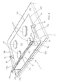
- a hob 10 which is inserted in known manner into a cooker top 14, comprises a plurality of rings 12 of known type, for instance gas or electric rings, and is equipped with a protection device 1 according to the invention for protecting the access to the hob itself, in particular by people at risk.
- Protection device 1 includes a pair of supporting brackets 3a, 3b arranged to be secured to top 14 receiving hob 10. Said supporting brackets 3a, 3b are secured to said top in known manner, for instance by screws or by gluing.
- Protection device 1 further includes a frame 5 pivotally mounted onto supporting brackets 3a, 3b by means of pivots 7a, 7b.
- Said frame 5 includes a screen 9 comprising a front wall 9c and two side members 9a, 9b.
- Said side members are L-shaped and have each an arm secured to front wall 9c and the other arm rigidly connected to one end of a corresponding side rod 11a, 11b, the opposite end of which is pivotally connected to a respective supporting bracket 3a, 3b.
- front wall 9c and side members 9a, 9b can be made as a single piece, whereby a substantially C-shaped screen 9 is obtained.
- supporting brackets 3a, 3b and screen 9 are so sized that pivots 7a, 7b to which side rods 11a, 11b of frame 5 are pivotally connected are at a level, i.e. at a distance from the base of supporting brackets 3a, 3b, substantially equal to half the height of front wall 9c of screen 9.
- Said frame 5 is preferably made of a material with high thermal conductivity, in particular a metal (for instance aluminium) or a metal alloy.
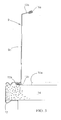
- front wall 9c of screen 9 may have, in its upper part, a bent edge 13a, preferably directed towards hob 10 so that it cannot be reached by people at risk (e.g. children), and equipped with a gasket 15, for instance made of rubber or similar material.
- bent edge 13a can be replaced by a handle with reduced size, located on top front wall 9c of screen 9.
- bent edge 13a besides providing a comfortable grip for moving screen 9, also gives a greater stiffness to front wall 9c of screen 9, thereby preventing its deformation.
- screen 9 may also have, in its lower part, a second bent edge 13b, equipped with a second gasket 15, for instance made of rubber or similar material and preferably identical to gasket 15a.
- Gasket 15b rests onto cooker top 14 receiving hob 10 and assists in slowing down a possible flow of liquids, for instance very hot liquids, boiled over pans present in the area of rings 12.
- supporting brackets 3a, 3b can be secured to top 14 substantially in correspondence of the middle point of a pair of opposite hob sides 10b, 10d, and frame 5 is preferably so sized that the overall size of each side rod 11a, 11b and the corresponding side member 9a, 9b of screen 9 slightly exceeds half the length of said opposite hob sides 10b, 10d.
- front wall 9c of screen 9 rests upon top 14 externally of hob 10 and is substantially parallel to a first hob side 10a, lying between said opposite sides 10b, 10d.
- side members 9a, 9b of screen 9 lick hob 10, so as to make the screen more stable.
- screen 9 in particular thanks to front wall 9c, thus prevents people at risk, such as children and aged or handicapped persons, from touching pans, if any, present on hob 10 and exposed to high temperatures, or from overturning such pans. Moreover screen 9, since it rests upon top 14 receiving hob 10, has no grips for being possibly lifted, and only an adult can access edge 13, advantageously bent towards the inside of screen 9.
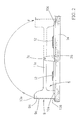
- frame 5 can be pivoted about pivots 7a, 7b by an angle of substantially 180° (arrow F in Fig. 2 ) in order to move from a first position, corresponding to the position shown in Fig. 1 , where front wall 9c of screen 9 rests on top 14 externally of hob 10 and is substantially parallel to a first side 10a of hob 10, to a second position, shown in dashed line in Fig. 2 , where said front wall 9c of screen 9 rests on top 14 externally of hob 10 and is substantially parallel to a second hob side 10c, opposite to said first side 10a.
- screen 9 does not hinder either the proper smoke suction or the proper lighting of the hob itself, since it is located outside hob 10 in both positions.
- front wall 9c of screen 9 is flat and substantially perpendicular to side rods 11a, 11b.
- the protection device according to the invention can be effectively used not only with hobs in cookers with a conventional linear structure, but also with hobs in cookers with an island structure.
- protection device 1 may advantageously include a C-shaped safety clip 17 made of a resilient material and arranged to lock the base of screen 19 to cooker top 14 receiving hob 10.
- safety clip 17 can keep bent edge 13b and gasket 15b provided at the base of front wall 9c of screen 9 against cooker top 14. In this manner, a fortuitous lifting of screen 9 by people at risk is wholly prevented.
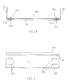
- FIG. 4 and 5 the system for connecting front wall 9c of screen 9 to side members 9a, 9b is shown in detail.
- Front wall 9c has, on each side, one or more slots 19a, 19b which are longitudinally arranged with respect to said front wall 9c, are parallel to each other and are vertically aligned (two slots on each side, in the illustrated example).
- each side member 9a, 9b has one or more throughholes 23a, 23b, also vertically aligned (two holes on each side, in the illustrated example), which can be superimposed to said slots for letting through fastening means 21a, 21b, such as screws, rivets or the like.
- slots 19a, 19b allows placing side members 9a, 9b nearer or farther relative to each other depending on the size of the hob to which the device is applied.
- the spacing of said side members 9a, 9b can be adapted to the size of hob 10 so that they lick hob 10, as described above.
Abstract
Description
- The present invention relates to a protection device for protecting the access to a hob (or cooking top). More particularly the present invention relates to a protection device to be applied to a cooker hob for safeguarding people at risk, such as children and aged or handicapped persons, against approaching the hob and especially containers placed on the rings of the hob while food is being cooked.
- Safety devices are known that are intended to prevent the access to a hob by people at risk (e.g. children and aged or handicapped persons), who could burn themselves by touching the containers placed on the rings or by spilling the contents of said containers on themselves.
- For instance,
AU-A-59355/86 - A similar device is disclosed also in
FR 2610704 - Said known devices have the drawback that the screen of the protection device, which is arranged to prevent the access to the cooking rings when in its operating position, in its rest position becomes a hindrance surface that prevents or hinders the suction of cooking smokes or gases and/or the lighting of the hob.
- Another drawback of the known devices is that they are to be equipped, in their rest position, with locking elements that are arranged to provide stability to the substantially vertical position of the safety device, what makes the device more complex and expensive.
- In the alternative, instead of including locking elements into the safety device, it is possible to envisage that, in its rest position, the device abuts against the wall behind the hob, but this makes devices of such kind unsuitable for application to hobs of cookers with a so-called "island" structure.
- In more general manner, the prior art devices cannot be used when the hob belongs to cookers with an island structure, where the hob itself can be accessed from two opposite sides.
- It is an object of the present invention to overcome the drawbacks of the prior art, by providing a protection device for hobs that, while providing a great protecting surface, does not hinder the flow of smokes and the lighting of the hob.
- It is a further object of the invention to provide a protection device that can be associated with hobs of any kind, especially with hobs of cookers with an island structure.
- The above and other objects are achieved by means of a protection device as claimed in the appended claims.
- The screen of the protection device according to the invention may be pivoted by an angle of substantially 180° about a pair of pivots that are located at substantially mid height of said screen. Thanks to such an arrangement, said screen can be moved from a first position, in which it rests on the cooker top receiving the hob, externally of the latter, in correspondence of a first side of said hob, to a second position, in which it also rests on the cooker top receiving the hob, externally of the latter, in correspondence of a second side of said hob, opposite to the first one.
- Advantageously, in both positions, the screen rests on the cooker top receiving the hob so as to be in a stable equilibrium condition. Thus, the need for locking means for keeping said screen in a predetermined position is avoided.
- Moreover, since in both positions the screen is always located externally of the hob, it is not of obstacle to the proper smoke suction and the proper lighting of the hob.
- The skilled in the art will immediately realise that the device according to the invention is particularly suited for use in cookers with an island structure, since it allows preventing access of people at risk to a hob from either a first side of the hob or from a second side of the hob, opposite to the first one, depending on the requirements.
- Otherwise stated, whereas in case of traditional cookers with linear structure it will be possible to identify an operating position, in which the protection screen is located between the user and the hob, and a rest position, in which the protection screen is located between the hob and the wall behind, in case of cookers with a so-called island structure the protection screen will move from a first operating position to a second operating position on each one of both opposite and accessible sides of the hob, respectively.
- Further features and advantages of the invention will become apparent from the following detailed description of an embodiment of the invention, given by way of example with reference to the accompanying drawings, in which:
-
Fig. 1 is a perspective view of a hob including the protection device according to the invention; -
Fig. 2 is a side view of the hob shown inFig. 1 ; -
Fig. 3 is an enlarged cross sectional view, taken along a median line, of a detail of the hob shown inFig. 1 , highlighting the front wall of the screen and the safety clip; -
Fig. 4 is a cross-sectional view of the protection device according to the invention, highlighting the system connecting the front wall and the side members of the screen; -
Fig. 5 is a front view of the front wall of the screen of the protection device according to the invention. - Referring to
Fig. 1 , there is shown ahob 10, which is inserted in known manner into acooker top 14, comprises a plurality ofrings 12 of known type, for instance gas or electric rings, and is equipped with a protection device 1 according to the invention for protecting the access to the hob itself, in particular by people at risk. - Protection device 1 includes a pair of supporting
brackets hob 10. Said supportingbrackets - Protection device 1 further includes a
frame 5 pivotally mounted onto supportingbrackets pivots 7a, 7b. - Said
frame 5 includes ascreen 9 comprising afront wall 9c and twoside members 9a, 9b. Said side members are L-shaped and have each an arm secured tofront wall 9c and the other arm rigidly connected to one end of acorresponding side rod 11a, 11b, the opposite end of which is pivotally connected to a respective supportingbracket - In the alternative,
front wall 9c andside members shaped screen 9 is obtained. - Advantageously, for reasons that will become apparent hereinafter, supporting
brackets screen 9 are so sized thatpivots 7a, 7b to whichside rods 11a, 11b offrame 5 are pivotally connected are at a level, i.e. at a distance from the base of supportingbrackets front wall 9c ofscreen 9. - Said
frame 5 is preferably made of a material with high thermal conductivity, in particular a metal (for instance aluminium) or a metal alloy. - Referring to
Fig. 3 ,front wall 9c ofscreen 9 may have, in its upper part, abent edge 13a, preferably directed towardshob 10 so that it cannot be reached by people at risk (e.g. children), and equipped with a gasket 15, for instance made of rubber or similar material. - Possibly,
bent edge 13a can be replaced by a handle with reduced size, located ontop front wall 9c ofscreen 9. - Yet,
bent edge 13a, besides providing a comfortable grip for movingscreen 9, also gives a greater stiffness tofront wall 9c ofscreen 9, thereby preventing its deformation. - Still referring to
Fig. 3 ,screen 9 may also have, in its lower part, asecond bent edge 13b, equipped with a second gasket 15, for instance made of rubber or similar material and preferably identical to gasket 15a. Gasket 15b rests ontocooker top 14 receivinghob 10 and assists in slowing down a possible flow of liquids, for instance very hot liquids, boiled over pans present in the area ofrings 12. - Turning back to
Fig. 1 , according to the invention, supportingbrackets top 14 substantially in correspondence of the middle point of a pair ofopposite hob sides frame 5 is preferably so sized that the overall size of eachside rod 11a, 11b and thecorresponding side member screen 9 slightly exceeds half the length of saidopposite hob sides front wall 9c ofscreen 9 rests upon top 14 externally ofhob 10 and is substantially parallel to afirst hob side 10a, lying between saidopposite sides side members screen 9lick hob 10, so as to make the screen more stable. - As it is apparent from
Fig. 1 ,screen 9, in particular thanks tofront wall 9c, thus prevents people at risk, such as children and aged or handicapped persons, from touching pans, if any, present onhob 10 and exposed to high temperatures, or from overturning such pans. Moreoverscreen 9, since it rests upon top 14 receivinghob 10, has no grips for being possibly lifted, and only an adult can accessedge 13, advantageously bent towards the inside ofscreen 9. - Turning now to
Fig. 2 , according to the invention,frame 5 can be pivoted aboutpivots 7a, 7b by an angle of substantially 180° (arrow F inFig. 2 ) in order to move from a first position, corresponding to the position shown inFig. 1 , wherefront wall 9c ofscreen 9 rests ontop 14 externally ofhob 10 and is substantially parallel to afirst side 10a ofhob 10, to a second position, shown in dashed line inFig. 2 , where saidfront wall 9c ofscreen 9 rests ontop 14 externally ofhob 10 and is substantially parallel to asecond hob side 10c, opposite to saidfirst side 10a. - It is apparent form
Fig. 2 that, sincepivots 7a, 7b about whichframe 5 is pivoted are substantially at mid height offront wall 9c ofscreen 9,frame 5 is at a stable equilibrium condition in both positions shown, withscreen 9 firmly resting ontop 14. - It is further to be appreciated that, once the screen has been moved to its second position shown in
Fig. 2 ,front wall 9c of saidscreen 9 rests onbent edge 13a and gasket 15a. The provision of such a gasket will allow slowing down, also in that second position of the screen, the flow of liquids boiled over pans present in the area ofrings 12. - Moreover,
screen 9 does not hinder either the proper smoke suction or the proper lighting of the hob itself, since it is located outsidehob 10 in both positions. - To this end, moreover,
front wall 9c ofscreen 9 is flat and substantially perpendicular toside rods 11a, 11b. - Moreover, the skilled in the art will readily appreciate that, since
screen 9, depending on the position taken byframe 5, can protect the access tohob 10 from twoopposite sides - Turning now to
Fig. 3 , protection device 1 according to the invention may advantageously include a C-shaped safety clip 17 made of a resilient material and arranged to lock the base of screen 19 tocooker top 14 receivinghob 10. - More particularly, as shown in
Fig. 3 ,safety clip 17 can keepbent edge 13b andgasket 15b provided at the base offront wall 9c ofscreen 9 againstcooker top 14. In this manner, a fortuitous lifting ofscreen 9 by people at risk is wholly prevented. - Referring to
Figs. 4 and 5 , the system for connectingfront wall 9c ofscreen 9 toside members -
Front wall 9c has, on each side, one ormore slots front wall 9c, are parallel to each other and are vertically aligned (two slots on each side, in the illustrated example). In similar manner, eachside member more throughholes - Advantageously, the provision of
slots side members side members hob 10 so that they lickhob 10, as described above. - The above description clearly shows that the present invention attains the desired objects, by providing a simple and cheap protection device, suitable for any kind of hob.
- Further, it is clear that changes and modifications in the reach of the skilled in the art can be introduced in the described embodiment, without thereby departing from the scope of the invention as claimed in the appended claims.
Claims (15)
- A protection device (1) for protecting the access to a hob (10), the device comprising:- a pair of supporting brackets (3a, 3b) arranged to be secured to a cooker top (14),- a frame (5) including a screen (9), comprising a front wall (9c) and two side members (9a, 9b), and a pair of side rods (11a, 11b), which are each rigidly connected to an opposite side member (9a, 9b) of said screen (9) at a first end and are pivotally connected to a respective supporting bracket (3a, 3b) by means of pivots (7a, 7b) at the opposite end;characterised in that said pivots are spaced from the base of said supporting brackets (3a, 3b) by a distance substantially equal to half the height of said front wall (9c) of said screen (9).
- The protection device (1) as claimed in claim 1, wherein said frame (5) can pivot about said pivots (7a, 7b) by an angle of substantially 180°.
- The protection device (1) as claimed in claim 1 or 2, wherein said front wall (9c) and said side members (9a, 9b) of said screen (9) are formed as a single piece.
- The protection device (1) as claimed in claim 1 or 2, wherein said side members (9a, 9b) of said screen are L-shaped and have each one arm secured to said front wall (9c) and the other arm rigidly connected to the end of a corresponding side rod (11a, 11b).
- The protection device (1) as claimed in claim 4, wherein said front wall (9c) has, on each side, one or more slots (19a, 19b), which are longitudinally arranged with respect to said front wall (9c), are parallel to each other and are vertically aligned, and, correspondingly, said side members (9a, 9b) have each one or more vertically aligned throughholes (23a, 23b), which can be superimposed to said slots for letting through fastening means (21a, 21b) such as screws, rivets or the like, for fastening said side members to said front wall.
- The protection device (1) as claimed in any of claims 1 to 5, wherein said front wall (9c) of said screen (9) has, in its upper part, a bent edge (13a) equipped with a gasket (15a), for instance made of rubber or similar material.
- The protection device (1) as claimed in any of claims 1 to 6, wherein said front wall (9c) of said screen (9) has, in its lower part, a bent edge (13b) equipped with a gasket (15b), for instance made of rubber or similar material.
- The protection device (1) as claimed in any of claims 1 to 5, wherein said front wall (9c) of said screen (9) has a grip in its upper part.
- The protection device (1) as claimed in any of claims 1 to 8, wherein said frame (5) is made of a material with high thermal conductivity.
- The protection device (1) as claimed in any of claims 1 to 9, further including a C-shaped safety clip (17) made of a resilient material and arranged to lock the base of said front wall (9c) of said screen (9) against said cooker top (14).
- A hob (10) inserted in a cooker top (14) and including a plurality of rings (12), characterised in that it includes a protection device as claimed in any of claims 1 to 10.
- The hob (10) as claimed in claim 11, wherein said supporting brackets (3a, 3b) are secured to said top (14) in which said hob (10) is received in correspondence of a pair of opposite sides (10b, 10d) of said hob (10).
- The hob (10) as claimed in claim 12, wherein said frame (5) can pivot about said pivots (7a, 7b) by an angle of substantially 180°, so that said screen (9) can be moved from a first position, in which said front wall (9c) rests onto said top (14) externally of said hob (10) and is substantially parallel to a first side (10a) of said hob (10) located between said pair of opposite sides (10b, 10d), to a second position in which said front wall (9c) rests on said cooker top (14) externally of said hob (10) and is substantially parallel to a second side (10c) of hob (10), located between said pair of opposite sides (10b, 10d) and opposite to said first side (10a).
- The hob (10) as claimed in any of claims 11 to 13, wherein said supporting brackets (3a, 3b) are secured to said top (14) substantially in correspondence of the middle points of said pair of opposite sides (10b, 10d), and the overall size of each side rod (11a, 11b) and the corresponding side member (9a, 9b) of said screen (9) slightly exceeds half the length of said opposite sides (10b, 10d) of said hob.
- The hob (10) as claimed in claim 12, wherein the spacing between said side members (9a, 9b) of said screen is substantially the same as the spacing between said opposite sides (10b, 10d) of said hob (10), so that said side members lick said hob.
Applications Claiming Priority (1)
| Application Number | Priority Date | Filing Date | Title |
|---|---|---|---|
| ITTO20090058 ITTO20090058U1 (en) | 2009-05-05 | 2009-05-05 | PROTECTIVE DEVICE TO PROTECT ACCESS TO A COOKING PLAN |
Publications (2)
| Publication Number | Publication Date |
|---|---|
| EP2249089A2 true EP2249089A2 (en) | 2010-11-10 |
| EP2249089A3 EP2249089A3 (en) | 2012-06-27 |
Family
ID=42641028
Family Applications (1)
| Application Number | Title | Priority Date | Filing Date |
|---|---|---|---|
| EP10161951A Withdrawn EP2249089A3 (en) | 2009-05-05 | 2010-05-05 | Protection device for protecting the access to a cooking top |
Country Status (2)
| Country | Link |
|---|---|
| EP (1) | EP2249089A3 (en) |
| IT (1) | ITTO20090058U1 (en) |
Cited By (2)
| Publication number | Priority date | Publication date | Assignee | Title |
|---|---|---|---|---|
| EP2901087A4 (en) * | 2012-09-17 | 2016-08-10 | Dnm Engineering Pty Ltd | Improved rack for holding cookware on a cooktop |
| EP4325127A1 (en) * | 2022-08-16 | 2024-02-21 | BSH Hausgeräte GmbH | A cooking appliance with a child protector |
Citations (2)
| Publication number | Priority date | Publication date | Assignee | Title |
|---|---|---|---|---|
| AU5935586A (en) | 1986-06-23 | 1987-12-24 | Boris Dobra | Hot plate child protection |
| FR2610704A1 (en) | 1987-02-10 | 1988-08-12 | Halvick Viviane | Cooker which includes, in particular, a pivoting protective plate |
Family Cites Families (3)
| Publication number | Priority date | Publication date | Assignee | Title |
|---|---|---|---|---|
| DE1139956B (en) * | 1955-10-07 | 1962-11-22 | Lars Eric Friberg | Protective device on gas or electric stoves |
| DE9108077U1 (en) * | 1991-07-01 | 1991-09-12 | Bosch-Siemens Hausgeraete Gmbh, 8000 Muenchen, De | |
| ITTO20050581A1 (en) * | 2005-08-18 | 2007-02-19 | Renato Ravizza | DEVICE TO PROTECT ACCESS TO A RELATIVE COOKING PLAN |
-
2009
- 2009-05-05 IT ITTO20090058 patent/ITTO20090058U1/en unknown
-
2010
- 2010-05-05 EP EP10161951A patent/EP2249089A3/en not_active Withdrawn
Patent Citations (2)
| Publication number | Priority date | Publication date | Assignee | Title |
|---|---|---|---|---|
| AU5935586A (en) | 1986-06-23 | 1987-12-24 | Boris Dobra | Hot plate child protection |
| FR2610704A1 (en) | 1987-02-10 | 1988-08-12 | Halvick Viviane | Cooker which includes, in particular, a pivoting protective plate |
Cited By (2)
| Publication number | Priority date | Publication date | Assignee | Title |
|---|---|---|---|---|
| EP2901087A4 (en) * | 2012-09-17 | 2016-08-10 | Dnm Engineering Pty Ltd | Improved rack for holding cookware on a cooktop |
| EP4325127A1 (en) * | 2022-08-16 | 2024-02-21 | BSH Hausgeräte GmbH | A cooking appliance with a child protector |
Also Published As
| Publication number | Publication date |
|---|---|
| ITTO20090058U1 (en) | 2010-11-06 |
| EP2249089A3 (en) | 2012-06-27 |
Similar Documents
| Publication | Publication Date | Title |
|---|---|---|
| US5546928A (en) | Grease splatter guard | |
| US4407189A (en) | Roast spit | |
| US11112124B2 (en) | Hinged cooktop grate assembly | |
| US5758636A (en) | Safety guard for stoves | |
| EP2249089A2 (en) | Protection device for protecting the access to a cooking top | |
| US4037581A (en) | Screen device for stove ovens | |
| US9861232B2 (en) | Non-electric, compact, variable width, perpendicular action stovetop toaster based on reflected infrared radiation (IR) | |
| US1735806A (en) | Shield for cook stoves | |
| US3423708A (en) | Magnetic holder for pots and pans | |
| US20220015571A1 (en) | Splatter protector | |
| US10136761B2 (en) | Grill attachment for portable heaters | |
| US163858A (en) | Improvement in attachments for cooking-stoves | |
| EP1767870A2 (en) | Device for protecting access to a cooking top | |
| CN208909901U (en) | Cooking equipment | |
| US20080241328A1 (en) | Passive heater | |
| US873589A (en) | Gridiron. | |
| EP2950003A1 (en) | Cover plate for a cooking top of a kitchen appliance | |
| US20050223952A1 (en) | Hanging fryer shelf | |
| JP3000914U (en) | Shelf member for cooking utensils | |
| JP3559302B2 (en) | Grill exhaust vent cover for system kitchen range | |
| CA2151318A1 (en) | Cooktop | |
| CN104106961B (en) | Simple multifunctional dish heat preservation device | |
| US2984236A (en) | Oven door cover | |
| JP2015038386A (en) | Oil spit guard panel | |
| BE1025991B1 (en) | Pot lid and cooking assembly with vapor passage |
Legal Events
| Date | Code | Title | Description |
|---|---|---|---|
| PUAI | Public reference made under article 153(3) epc to a published international application that has entered the european phase |
Free format text: ORIGINAL CODE: 0009012 |
|
| AK | Designated contracting states |
Kind code of ref document: A2 Designated state(s): AL AT BE BG CH CY CZ DE DK EE ES FI FR GB GR HR HU IE IS IT LI LT LU LV MC MK MT NL NO PL PT RO SE SI SK SM TR |
|
| AX | Request for extension of the european patent |
Extension state: BA ME RS |
|
| PUAL | Search report despatched |
Free format text: ORIGINAL CODE: 0009013 |
|
| AK | Designated contracting states |
Kind code of ref document: A3 Designated state(s): AL AT BE BG CH CY CZ DE DK EE ES FI FR GB GR HR HU IE IS IT LI LT LU LV MC MK MT NL NO PL PT RO SE SI SK SM TR |
|
| AX | Request for extension of the european patent |
Extension state: BA ME RS |
|
| RIC1 | Information provided on ipc code assigned before grant |
Ipc: F24C 15/36 20060101AFI20120522BHEP |
|
| STAA | Information on the status of an ep patent application or granted ep patent |
Free format text: STATUS: THE APPLICATION IS DEEMED TO BE WITHDRAWN |
|
| 18D | Application deemed to be withdrawn |
Effective date: 20130103 |