EP2249034A2 - Method and device for mixing fluids - Google Patents
Method and device for mixing fluids Download PDFInfo
- Publication number
- EP2249034A2 EP2249034A2 EP20100004529 EP10004529A EP2249034A2 EP 2249034 A2 EP2249034 A2 EP 2249034A2 EP 20100004529 EP20100004529 EP 20100004529 EP 10004529 A EP10004529 A EP 10004529A EP 2249034 A2 EP2249034 A2 EP 2249034A2
- Authority
- EP
- European Patent Office
- Prior art keywords
- fluids
- pump
- drive
- suction
- valves
- Prior art date
- Legal status (The legal status is an assumption and is not a legal conclusion. Google has not performed a legal analysis and makes no representation as to the accuracy of the status listed.)
- Withdrawn
Links
Images
Classifications
-
- F—MECHANICAL ENGINEERING; LIGHTING; HEATING; WEAPONS; BLASTING
- F04—POSITIVE - DISPLACEMENT MACHINES FOR LIQUIDS; PUMPS FOR LIQUIDS OR ELASTIC FLUIDS
- F04B—POSITIVE-DISPLACEMENT MACHINES FOR LIQUIDS; PUMPS
- F04B13/00—Pumps specially modified to deliver fixed or variable measured quantities
- F04B13/02—Pumps specially modified to deliver fixed or variable measured quantities of two or more fluids at the same time
-
- B—PERFORMING OPERATIONS; TRANSPORTING
- B01—PHYSICAL OR CHEMICAL PROCESSES OR APPARATUS IN GENERAL
- B01F—MIXING, e.g. DISSOLVING, EMULSIFYING OR DISPERSING
- B01F25/00—Flow mixers; Mixers for falling materials, e.g. solid particles
- B01F25/60—Pump mixers, i.e. mixing within a pump
-
- B—PERFORMING OPERATIONS; TRANSPORTING
- B01—PHYSICAL OR CHEMICAL PROCESSES OR APPARATUS IN GENERAL
- B01F—MIXING, e.g. DISSOLVING, EMULSIFYING OR DISPERSING
- B01F35/00—Accessories for mixers; Auxiliary operations or auxiliary devices; Parts or details of general application
- B01F35/80—Forming a predetermined ratio of the substances to be mixed
- B01F35/83—Forming a predetermined ratio of the substances to be mixed by controlling the ratio of two or more flows, e.g. using flow sensing or flow controlling devices
- B01F35/831—Forming a predetermined ratio of the substances to be mixed by controlling the ratio of two or more flows, e.g. using flow sensing or flow controlling devices using one or more pump or other dispensing mechanisms for feeding the flows in predetermined proportion, e.g. one of the pumps being driven by one of the flows
-
- B—PERFORMING OPERATIONS; TRANSPORTING
- B01—PHYSICAL OR CHEMICAL PROCESSES OR APPARATUS IN GENERAL
- B01F—MIXING, e.g. DISSOLVING, EMULSIFYING OR DISPERSING
- B01F23/00—Mixing according to the phases to be mixed, e.g. dispersing or emulsifying
- B01F23/10—Mixing gases with gases
-
- B—PERFORMING OPERATIONS; TRANSPORTING
- B01—PHYSICAL OR CHEMICAL PROCESSES OR APPARATUS IN GENERAL
- B01F—MIXING, e.g. DISSOLVING, EMULSIFYING OR DISPERSING
- B01F23/00—Mixing according to the phases to be mixed, e.g. dispersing or emulsifying
- B01F23/20—Mixing gases with liquids
-
- B—PERFORMING OPERATIONS; TRANSPORTING
- B01—PHYSICAL OR CHEMICAL PROCESSES OR APPARATUS IN GENERAL
- B01F—MIXING, e.g. DISSOLVING, EMULSIFYING OR DISPERSING
- B01F23/00—Mixing according to the phases to be mixed, e.g. dispersing or emulsifying
- B01F23/40—Mixing liquids with liquids; Emulsifying
-
- Y—GENERAL TAGGING OF NEW TECHNOLOGICAL DEVELOPMENTS; GENERAL TAGGING OF CROSS-SECTIONAL TECHNOLOGIES SPANNING OVER SEVERAL SECTIONS OF THE IPC; TECHNICAL SUBJECTS COVERED BY FORMER USPC CROSS-REFERENCE ART COLLECTIONS [XRACs] AND DIGESTS
- Y10—TECHNICAL SUBJECTS COVERED BY FORMER USPC
- Y10T—TECHNICAL SUBJECTS COVERED BY FORMER US CLASSIFICATION
- Y10T137/00—Fluid handling
- Y10T137/8593—Systems
- Y10T137/85978—With pump
Definitions
- the invention relates to a method for mixing fluids according to the preamble of claim 1.
- the invention also relates to an apparatus for carrying out this method according to the preamble of claim 7.
- Such fluids may be gaseous and / or liquid, often requiring that one fluid be mixed with the other fluid reliably.
- the procedure is usually such that in each case two mutually separate fluids are sucked by means of pump force via a respective suction line and conveyed by means of pump pressure stroke in a delivery line.
- each fluid is associated with its own delivery pump, which is the suction side via a respective suction line with the fluid in question, while the pressure line of each pump is connected to a common delivery line.
- the invention is therefore based on the object, the method of the generic type to eliminate the disadvantages described in such a way that it can be carried out more economically and with a more reliable mixing result.
- the inventive method is based on the idea to perform the mixing of the fluids in the pump head of a single oscillating positive displacement pump whose drive is controlled such that according to the quantitative ratio of the fluids to be mixed Suction stroke of the drive is split over its rotation angle into individual sections, during which the fluids are sucked into the pump head successively via their suction line, whereupon during the subsequent pump pressure stroke the fluids already mixed in the pump head are ejected into the delivery line.
- control of the pump drive acts on valves in the suction lines of the fluids to be mixed, such that at the beginning of the pump suction stroke the valve in the suction line of the first fluid is opened and this fluid is sucked into the pump head, whereupon upon reaching the predefined angle of rotation closes the valve of the first suction line and the valve of the at least one further suction line is opened, whereupon the at least further fluid is sucked into the pump head until the end of the suction stroke.
- the distribution of the angle of rotation of the pump drive is calculated according to the mixing ratio of the fluids. This makes it possible in a simple manner to adjust the mixing ratio of the fluids via the drive control.
- the pump drive is stopped upon reaching each rotational angle section for switching the valves of the suction lines.
- volume flow of the fluid mixture is adjusted via the drive speed.
- the inventively provided device for carrying out the described method is designed such that the valves provided with suction lines of at least two fluids to be mixed are connected to the pump head of a single oscillating positive displacement pump whose drive control is designed to switch the valves.
- the drive of the oscillating positive displacement pump is a highly dynamic drive.
- This is preferably a servo motor, in particular a permanent-magnet three-phase synchronous servo motor.
- the oscillating positive displacement pump is a diaphragm pump.
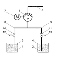
- two fluids 1, 2, which are provided separately in containers 3, 4, are mixed with each other so that they are conveyed after the mixture in a common feed line 5 on.
- a single oscillating positive displacement pump 6 is provided, which in the illustrated embodiment as Diaphragm pump is designed. This is provided with a highly dynamic drive 7 including a corresponding control.
- the valves 10, 11 are provided with corresponding controls 12, 13, which are in communication with the pump drive 7 and its control.
- the pump drive 7 and its control for switching the valves 10, 11 configured, in such a way that divided according to the ratio of the fluids to be mixed 1, 2 of the suction stroke of the pump 6 and the pump drive 7 via its rotation angle in individual sections is, during which the fluids 1, 2 are sucked via their suction lines 8, 9 successively in the pump head. Then, in the subsequent pump pressure stroke, the fluids 1, 2 already mixed in the pump head are ejected into the delivery line 5.
- the control of the pump drive 7 acts on the valves 10, 11 in the suction lines 8, 9 of the fluids to be mixed 1, 2 such that at the beginning of the pumping suction valve 10 in the suction line 8 of the first fluid 1 is opened, whereupon Reaching the predefined angle of rotation, the valve 10 of the first suction line 8 is closed and the valve 11 of the second suction line 9 is opened and the second fluid 2 is sucked into the pump head until the end of the suction stroke.
- the distribution of the angle of rotation of the pump drive 7 is carried out according to the mixing ratio of the fluids 1, 2, which is done by suitable calculation.
- the pump drive 7 is upon reaching each rotation angle section to switch over the valves 10, 11 of the suction lines 8, 9 stopped.
- the suction stroke of the pump drive 7 is divided over the rotation angle corresponding to the quantitative ratio of the two fluids 1, 2.
- the valve 10 is opened for the fluid 1 during the suction stroke of the pump 6 in the front dead center, so that this fluid 1 is sucked into the pump head via the suction line 8.
- the pump drive 7 stops and the valves 10, 11 are switched over, i. the valve 10 is closed while the valve 11 is opened.
- the pump 6 sucks the fluid 2 via the open suction line 9 into the pump head during the second section of the suction stroke.
- the valve 11 is then closed.
- the pump drive 7 then pushes the pump 6, the fluid mixture in the common supply line 5 from.
Abstract
Description
Die Erfindung betrifft ein Verfahren zum Mischen von Fluiden gemäß dem Oberbegriff des Anspruchs 1.The invention relates to a method for mixing fluids according to the preamble of
Die Erfindung betrifft außerdem eine Vorrichtung zur Durchführung dieses Verfahrens gemäß dem Oberbegriff des Anspruchs 7.The invention also relates to an apparatus for carrying out this method according to the preamble of
Derartige Fluide können gasförmig und/oder flüssig sein, wobei häufig die Anforderung besteht, das eine Fluid mit dem anderen Fluid zuverlässig zu mischen.Such fluids may be gaseous and / or liquid, often requiring that one fluid be mixed with the other fluid reliably.
Zu diesem Zweck wird üblicherweise derart vorgegangen, dass jeweils zwei voneinander gesonderte Fluide mittels Pumpenkraft über jeweils eine Saugleitung angesaugt und mittels Pumpendruckhub in eine Förderleitung befördert werden.For this purpose, the procedure is usually such that in each case two mutually separate fluids are sucked by means of pump force via a respective suction line and conveyed by means of pump pressure stroke in a delivery line.
Hierbei ist jedem Fluid eine eigene Förderpumpe zugeordnet, die saugseitig über jeweils eine Saugleitung mit dem betreffenden Fluid in Verbindung steht, während die Druckleitung jeder Pumpe an eine gemeinsame Förderleitung angeschlossen ist.Here, each fluid is associated with its own delivery pump, which is the suction side via a respective suction line with the fluid in question, while the pressure line of each pump is connected to a common delivery line.
Bei dem bekannten Verfahren erfolgt demgemäß die Mischung der Fluide auf der Druckseite der Pumpen, nämlich dann, wenn die Pumpendruckleitungen in die gemeinsame Förderleitung münden.In the known method, accordingly, the mixture of fluids on the pressure side of the pump takes place, namely, when the pump pressure lines open into the common delivery line.
Obwohl bei einem derartigen bekannten Verfahren zum Mischen von Fluiden durchaus zufrieden stellende Mischergebnisse in der Förderleitung erzielt werden können, ist gleichwohl der Nachteil gegeben, dass der konstruktive Aufwand hierfür nicht unbeträchtlich ist. Dies gilt insbesondere dann, wenn mehr als zwei Fluide miteinander zu mischen sind, da für jedes weitere Fluid dann auch eine eigene Förderpumpe erforderlich ist.Although in such a known method for mixing fluids quite satisfactory mixing results in the delivery line can be achieved, however, there is the disadvantage that the design effort for this is not inconsiderable. This is especially true when more than two fluids are to be mixed with each other, as for each additional fluid then a separate pump is required.
Der Erfindung liegt daher die Aufgabe zugrunde, das Verfahren der gattungsgemäßen Art zur Beseitigung der geschilderten Nachteile derart auszugestalten, dass es wirtschaftlicher sowie mit einem zuverlässigeren Mischungsergebnis durchführbar ist.The invention is therefore based on the object, the method of the generic type to eliminate the disadvantages described in such a way that it can be carried out more economically and with a more reliable mixing result.
Außerdem soll eine Vorrichtung zur Durchführung dieses Verfahrens geschaffen werden, die einen geringeren konstruktiven Aufwand aufweist.In addition, a device for carrying out this method is to be created, which has a lower design complexity.
Diese Aufgabe wird mit der Erfindung durch die Merkmale des Anspruchs 1 gelöst. Vorteilhafte Ausgestaltungen hiervon sind in den weiteren Ansprüchen beschrieben.This object is achieved with the invention by the features of
Die Merkmale der erfindungsgemäß geschaffenen Vorrichtung ergeben sich aus Anspruch 7. Vorteilhafte Ausgestaltungen hiervon sind in den weiteren Ansprüchen aufgeführt.The features of the inventively created device will become apparent from
Dem erfindungsgemäßen Verfahren liegt der Gedanke zugrunde, das Mischen der Fluide im Pumpenkopf einer einzigen oszillierenden Verdrängerpumpe durchzuführen, deren Antrieb derart gesteuert wird, dass entsprechend dem Mengenverhältnis der zu mischenden Fluide der Saughub des Antriebs über dessen Drehwinkel in einzelne Abschnitte aufgeteilt wird, während denen die Fluide über ihre Saugleitung nacheinander in den Pumpenkopf angesaugt werden, worauf beim anschließenden Pumpendruckhub die bereits im Pumpenkopf gemischten Fluide in die Förderleitung ausgestoßen werden.The inventive method is based on the idea to perform the mixing of the fluids in the pump head of a single oscillating positive displacement pump whose drive is controlled such that according to the quantitative ratio of the fluids to be mixed Suction stroke of the drive is split over its rotation angle into individual sections, during which the fluids are sucked into the pump head successively via their suction line, whereupon during the subsequent pump pressure stroke the fluids already mixed in the pump head are ejected into the delivery line.
Aufgrund dieses Vorgehens ist auf verblüffend einfache Weise gewährleistet, dass im einzigen Pumpenkopf der vorgesehenen oszillierenden Verdrängerpumpe eine zuverlässige Mischung der Fluide erfolgt, die dann in bereits ausreichend gemischter Form beim Druckhub der Pumpe in die Förderleitung ausgestoßen werden.Because of this procedure is ensured in an amazingly simple way that in the single pump head of the proposed oscillating positive displacement pump, a reliable mixture of fluids takes place, which are then ejected in already sufficiently mixed form during the pressure stroke of the pump in the delivery line.
In erfindungsgemäßer Ausgestaltung ist vorgesehen, dass die Steuerung des Pumpenantriebs auf Ventile in den Saugleitungen der zu mischenden Fluide einwirkt, derart, dass zu Beginn des Pumpensaughubs das Ventil in der Saugleitung des ersten Fluids geöffnet und dieses Fluid in den Pumpenkopf angesaugt wird, worauf beim Erreichen des vordefinierten Drehwinkels das Ventil der ersten Saugleitung geschlossen und das Ventil der wenigstens weiteren Saugleitung geöffnet wird, worauf das wenigstens weitere Fluid bis zum Ende des Saughubs in den Pumpenkopf gesaugt wird.In an embodiment according to the invention, it is provided that the control of the pump drive acts on valves in the suction lines of the fluids to be mixed, such that at the beginning of the pump suction stroke the valve in the suction line of the first fluid is opened and this fluid is sucked into the pump head, whereupon upon reaching the predefined angle of rotation closes the valve of the first suction line and the valve of the at least one further suction line is opened, whereupon the at least further fluid is sucked into the pump head until the end of the suction stroke.
In weiterer Ausgestaltung der Erfindung ist vorgesehen, dass die Aufteilung des Drehwinkels des Pumpenantriebs entsprechend dem Mischungsverhältnis der Fluide berechnet wird. Hierdurch ist es auf einfache Weise möglich, das Mischungsverhältnis der Fluide über die Antriebssteuerung einzustellen.In a further embodiment of the invention it is provided that the distribution of the angle of rotation of the pump drive is calculated according to the mixing ratio of the fluids. This makes it possible in a simple manner to adjust the mixing ratio of the fluids via the drive control.
Zweckmäßigerweise wird der Pumpenantrieb beim Erreichen jedes Drehwinkelabschnittes zum Umschalten der Ventile der Saugleitungen gestoppt.Conveniently, the pump drive is stopped upon reaching each rotational angle section for switching the valves of the suction lines.
Hinsichtlich der Einstellung des Mischungsverhältnisses der Fluide wird im speziellen derart vorgegangen, dass dieses über die Antriebssteuerung eingestellt wird.With regard to the adjustment of the mixing ratio of the fluids is in special procedure such that this is set via the drive control.
Es liegt schließlich im Rahmen der Erfindung, dass der Volumenstrom der Fluidmischung über die Antriebsdrehzahl eingestellt wird.It is finally within the scope of the invention that the volume flow of the fluid mixture is adjusted via the drive speed.
Die erfindungsgemäß vorgesehene Vorrichtung zur Durchführung des beschriebenen Verfahrens ist derart ausgestaltet, dass die mit Ventilen versehenen Saugleitungen von wenigstens zwei zu mischenden Fluiden an den Pumpenkopf einer einzigen oszillierenden Verdrängerpumpe angeschlossen sind, deren Antriebssteuerung zum Umschalten der Ventile ausgestaltet ist.The inventively provided device for carrying out the described method is designed such that the valves provided with suction lines of at least two fluids to be mixed are connected to the pump head of a single oscillating positive displacement pump whose drive control is designed to switch the valves.
Besondere Vorteile ergeben sich, wenn der Antrieb der oszillierenden Verdrängerpumpe ein hochdynamischer Antrieb ist. Dies ist vorzugsweise ein Servomotor, und zwar insbesondere ein permanenterregter Drehstrom-Synchronservomotor.Special advantages arise when the drive of the oscillating positive displacement pump is a highly dynamic drive. This is preferably a servo motor, in particular a permanent-magnet three-phase synchronous servo motor.
Ähnliche Vorteile ergeben sich, wenn erfindungsgemäß die oszillierende Verdrängerpumpe eine Membranpumpe ist.Similar advantages arise when according to the invention, the oscillating positive displacement pump is a diaphragm pump.
Die Erfindung wird im Folgenden in Form eines Ausführungsbeispiels anhand der Zeichnung näher erläutert. Diese zeigt in der einzigen Figur schematisch die Anordnung der erfindungsgemäßen Mischvorrichtung zur Durchführung des beschriebenen Verfahrens.The invention is explained in more detail below in the form of an embodiment with reference to the drawing. This shows in the single figure schematically the arrangement of the mixing device according to the invention for carrying out the method described.
Wie aus der Zeichnung ersichtlich, sollen zwei Fluide 1, 2, die gesondert voneinander in Behältern 3, 4 vorgesehen sind, derart miteinander gemischt werden, dass sie nach erfolgter Mischung in einer gemeinsamen Förderleitung 5 weiter befördert werden.As can be seen from the drawing, two
Zu diesem Zweck ist eine einzige oszillierende Verdrängerpumpe 6 vorgesehen, die beim dargestellten Ausführungsbeispiel als Membranpumpe ausgestaltet ist. Diese ist mit einem hochdynamischen Antrieb 7 einschließlich einer entsprechenden Steuerung versehen.For this purpose, a single oscillating
An die Druckseite der Pumpe 6 ist die die gemischten Fluide 1, 2 aufnehmende Förderleitung 5 angeschlossen. Demgegenüber sind an der Saugseite der Pumpe 6 jeweils Saugleitungen 8, 9 angeschlossen, die mit den Fluiden 1, 2 in Verbindung stehen und jeweils durch Ventile 10, 11 geöffnet bzw. geschlossen werden können. Zu diesem Zweck sind die Ventile 10, 11 mit entsprechenden Steuerungen 12, 13 versehen, die mit dem Pumpenantrieb 7 bzw. dessen Steuerung in Verbindung stehen.At the pressure side of the
Hierbei ist der Pumpenantrieb 7 bzw. dessen Steuerung zum Umschalten der Ventile 10, 11 ausgestaltet, und zwar derart, dass entsprechend dem Mengenverhältnis der zu mischenden Fluide 1, 2 der Saughub der Pumpe 6 bzw. des Pumpenantriebs 7 über dessen Drehwinkel in einzelne Abschnitte aufgeteilt wird, während denen die Fluide 1, 2 über ihre Saugleitungen 8, 9 nacheinander in den Pumpenkopf angesaugt werden. Darauf werden dann beim anschließenden Pumpendruckhub die bereits im Pumpenkopf gemischten Fluide 1, 2 in die Förderleitung 5 ausgestoßen.Here, the
Somit wirkt die Steuerung des Pumpenantriebs 7 auf die Ventile 10, 11 in den Saugleitungen 8, 9 der zu mischenden Fluide 1, 2 derart ein, dass zu Beginn des Pumpensaughubs das Ventil 10 in der Saugleitung 8 des ersten Fluids 1 geöffnet wird, worauf beim Erreichen des vordefinierten Drehwinkels das Ventil 10 der ersten Saugleitung 8 geschlossen und das Ventil 11 der zweiten Saugleitung 9 geöffnet sowie das zweite Fluid 2 bis zum Ende des Saughubs in den Pumpenkopf gesaugt wird. Wie schon dargelegt, erfolgt die Aufteilung des Drehwinkels des Pumpenantriebs 7 entsprechend dem Mischungsverhältnis der Fluide 1, 2, was durch geeignete Berechnung erfolgt.Thus, the control of the
Der Pumpenantrieb 7 wird beim Erreichen jedes Drehwinkelabschnittes zum Umschalten der Ventile 10, 11 der Saugleitungen 8, 9 gestoppt.The
Es ist somit auf einfache Weise möglich, mittels des beschriebenen Verfahrens bzw. der beschriebenen Vorrichtung zwei oder mehr Fluide im Pumpenkopf einer einzigen oszillierenden Verdrängerpumpe zu mischen. Zu diesem Zweck wird der Saughub des Pumpenantriebs 7 über den Drehwinkel entsprechend dem Mengenverhältnis der beiden Fluide 1, 2 aufgeteilt. Hierbei wird beim Saughub der Pumpe 6 in deren vorderem Totpunkt das Ventil 10 für das Fluid 1 geöffnet, so dass dieses Fluid 1 über die Saugleitung 8 in den Pumpenkopf eingesaugt wird. Beim Erreichen des berechneten Drehwinkels stoppt der Pumpenantrieb 7, und die Ventile 10, 11 werden umgeschaltet, d.h. das Ventil 10 wird geschlossen, während das Ventil 11 geöffnet wird. Nun saugt die Pumpe 6 das Fluid 2 über die geöffnete Saugleitung 9 in den Pumpenkopf während des zweiten Abschnittes des Saughubes ein. Im hinteren Totpunkt des Saughubes der Pumpe 6 wird sodann das Ventil 11 geschlossen. Nach dem erneuten Start des Pumpenantriebs 7 schiebt sodann die Pumpe 6 die Fluidmischung in die gemeinsame Förderleitung 5 aus.It is thus possible in a simple manner, by means of the described method or the device described to mix two or more fluids in the pump head of a single oscillating positive displacement pump. For this purpose, the suction stroke of the
Hinsichtlich vorstehend nicht im Einzelnen erläuterter Merkmale der Erfindung wird abschließend ausdrücklich auf die Ansprüche sowie die Zeichnung verwiesen.With regard to features of the invention which are not explained in detail above, reference is expressly made to the claims and the drawings.
Claims (9)
dadurch gekennzeichnet,
dass das Mischen der Fluide (1, 2) im Pumpenkopf einer einzigen oszillierenden Verdrängerpumpe (6) erfolgt, deren Antrieb (7) derart gesteuert wird, dass entsprechend dem Mengenverhältnis der zu mischenden Fluide (1, 2) der Saughub des Antriebs (7) über dessen Drehwinkel in einzelne Abschnitte aufgeteilt wird, während denen die Fluide (1, 2) über ihre Saugleitung (8, 9) nacheinander in den Pumpenkopf angesaugt werden, worauf beim anschließenden Pumpendruckhub die bereits im Pumpenkopf gemischten Fluide (1, 2) in die Förderleitung (5) ausgestoßen werden.Method for mixing fluids, wherein at least two mutually separate fluids (1, 2) are sucked by means of pumping force via in each case one suction line (8, 9) and conveyed by means of pump pressure stroke into a delivery line (5),
characterized,
in that the mixing of the fluids (1, 2) in the pump head is effected by a single oscillating displacement pump (6) whose drive (7) is controlled such that the suction stroke of the drive (7) corresponds to the quantity ratio of the fluids (1, 2) to be mixed. is divided over the angle of rotation into individual sections, during which the fluids (1, 2) via their suction line (8, 9) are successively sucked into the pump head, whereupon in the subsequent pump pressure stroke the already mixed in the pump head fluids (1, 2) in the Delivery line (5) are ejected.
Applications Claiming Priority (1)
| Application Number | Priority Date | Filing Date | Title |
|---|---|---|---|
| DE200910020412 DE102009020412A1 (en) | 2009-05-08 | 2009-05-08 | Method and device for mixing fluids |
Publications (2)
| Publication Number | Publication Date |
|---|---|
| EP2249034A2 true EP2249034A2 (en) | 2010-11-10 |
| EP2249034A3 EP2249034A3 (en) | 2011-06-15 |
Family
ID=42338981
Family Applications (1)
| Application Number | Title | Priority Date | Filing Date |
|---|---|---|---|
| EP20100004529 Withdrawn EP2249034A3 (en) | 2009-05-08 | 2010-04-29 | Method and device for mixing fluids |
Country Status (4)
| Country | Link |
|---|---|
| US (1) | US20100288381A1 (en) |
| EP (1) | EP2249034A3 (en) |
| JP (1) | JP2010264442A (en) |
| DE (1) | DE102009020412A1 (en) |
Families Citing this family (2)
| Publication number | Priority date | Publication date | Assignee | Title |
|---|---|---|---|---|
| CN106641731B (en) * | 2017-01-20 | 2021-04-20 | 荆州嘉华科技有限公司 | Pressure-regulating energy-saving device and method for fluid transmission and distribution system |
| EP3633328A1 (en) * | 2018-10-05 | 2020-04-08 | Covestro Deutschland AG | Method for adjusting the volumetric flow rate ratio of at least two different fluids |
Family Cites Families (12)
| Publication number | Priority date | Publication date | Assignee | Title |
|---|---|---|---|---|
| US4018685A (en) * | 1975-10-24 | 1977-04-19 | Union Oil Company Of California | Automatic liquid mixing device |
| US3985019A (en) * | 1975-11-10 | 1976-10-12 | Boehme Detlef R | Liquid chromatography system with solvent proportioning |
| DE2612826A1 (en) * | 1976-03-26 | 1977-09-29 | Weber Kg Ernst | Metering pump for use with delivery pump - is membrane operated from delivery pump and has adjustable volume |
| US4437812A (en) * | 1977-05-13 | 1984-03-20 | Varian Associates, Inc. | Single-pump multiple stroke proportioning for gradient elution liquid chromatography |
| JPS53141698A (en) * | 1977-05-13 | 1978-12-09 | Varian Associates | Regulation of single pump multistroke mixing ratio for mixed eluate liquid chromatography |
| JPS59117451A (en) * | 1982-12-24 | 1984-07-06 | Fanuc Ltd | Synchronous electric rotary machine |
| DE3546189A1 (en) * | 1985-12-27 | 1987-07-02 | Ott Kg Lewa | METHOD AND DEVICE FOR MEASURING FLOW IN OSCILLATING DISPLACEMENT PUMPS |
| FR2624919B1 (en) * | 1987-12-17 | 1990-04-27 | Milton Roy Dosapro | DEVICE FOR ADJUSTING THE FLOW OF AN ALTERNATIVE DOSING PUMP |
| DE19849785C1 (en) * | 1998-10-28 | 2000-03-16 | Ott Kg Lewa | Method and device for adjusting feed in oscillating positive-displacement pumps driven by means of driving motor using a rotating shaft and a driving mechanism such as crank gearing, gives versatility in operation |
| TW509738B (en) * | 1999-03-25 | 2002-11-11 | Barmag Barmer Maschf | Lubrication apparatus and method of applying a lubricant |
| FR2836185B1 (en) * | 2002-02-21 | 2004-10-15 | Inst Francais Du Petrole | METHOD AND SYSTEM FOR THE FINE DOSING OF INJECTED FLUIDS IN A PUMP INSATLLATION |
| US7972058B2 (en) * | 2005-03-16 | 2011-07-05 | Pendotech | Apparatus and method for mixing with a diaphragm pump |
-
2009
- 2009-05-08 DE DE200910020412 patent/DE102009020412A1/en not_active Withdrawn
-
2010
- 2010-04-29 EP EP20100004529 patent/EP2249034A3/en not_active Withdrawn
- 2010-05-06 US US12/775,162 patent/US20100288381A1/en not_active Abandoned
- 2010-05-10 JP JP2010107948A patent/JP2010264442A/en active Pending
Non-Patent Citations (1)
| Title |
|---|
| None |
Also Published As
| Publication number | Publication date |
|---|---|
| EP2249034A3 (en) | 2011-06-15 |
| DE102009020412A1 (en) | 2010-11-18 |
| US20100288381A1 (en) | 2010-11-18 |
| JP2010264442A (en) | 2010-11-25 |
Similar Documents
| Publication | Publication Date | Title |
|---|---|---|
| DE102005024731A1 (en) | Filling device for filling drinking liquid | |
| DE102012000017A1 (en) | Method for controlling a hydraulic press | |
| EP2867531B1 (en) | Movable concrete pump and method for use thereof in the transport state | |
| EP2907386B1 (en) | Fluid conveying system | |
| DE3024139C2 (en) | Two-cylinder nitrogen pump | |
| EP2249034A2 (en) | Method and device for mixing fluids | |
| DE10246946B4 (en) | Device for coating substrates in a printing machine | |
| DE112013004977B4 (en) | Hydraulic drive system and method for driving a belt conveyor | |
| DE102016007061A1 (en) | Conveying system for bulk material, in particular plastic granules, and method for conveying bulk material, in particular plastic granules | |
| DE102009020414A1 (en) | Homogenization of the flow rate in oscillating positive displacement pumps | |
| DE2231172C3 (en) | Process and device for biological wastewater treatment | |
| DE10115233C5 (en) | Horizontal drilling rig | |
| EP2732740A1 (en) | Device for emulsifying a mixture of air, steam and milk | |
| DE3490138C2 (en) | Installation for de-icing | |
| EP2062719B1 (en) | Screen changer | |
| DE3504107A1 (en) | Hydraulic dosing and delivery system | |
| EP2665677B1 (en) | Rotary distributing arrangement and method for operating a rotary distributing arrangement | |
| DE102008043587A1 (en) | Arrangement for adjusting an aircraft propeller | |
| DE102021005432A1 (en) | Gluing device | |
| WO2014166639A1 (en) | Two-cylinder thick matter pump | |
| DE1503676C3 (en) | Device for generating compressed air for aluminothermic welding | |
| DE132883C (en) | ||
| WO2019170533A1 (en) | Feed device for feeding recipe material for an extrusion process in an extrusion device | |
| DE202004010109U1 (en) | Fuel supply system for internal combustion engines has two tanks with controlled flow valves to provide balanced consumption | |
| DE1254038B (en) | Hydraulic steering for two-way self-propelled machines |
Legal Events
| Date | Code | Title | Description |
|---|---|---|---|
| PUAI | Public reference made under article 153(3) epc to a published international application that has entered the european phase |
Free format text: ORIGINAL CODE: 0009012 |
|
| AK | Designated contracting states |
Kind code of ref document: A2 Designated state(s): AT BE BG CH CY CZ DE DK EE ES FI FR GB GR HR HU IE IS IT LI LT LU LV MC MK MT NL NO PL PT RO SE SI SK SM TR |
|
| AX | Request for extension of the european patent |
Extension state: AL BA ME RS |
|
| REG | Reference to a national code |
Ref country code: DE Ref legal event code: R079 Free format text: PREVIOUS MAIN CLASS: F04B0013020000 Ipc: B01F0005120000 |
|
| PUAL | Search report despatched |
Free format text: ORIGINAL CODE: 0009013 |
|
| AK | Designated contracting states |
Kind code of ref document: A3 Designated state(s): AT BE BG CH CY CZ DE DK EE ES FI FR GB GR HR HU IE IS IT LI LT LU LV MC MK MT NL NO PL PT RO SE SI SK SM TR |
|
| AX | Request for extension of the european patent |
Extension state: AL BA ME RS |
|
| RIC1 | Information provided on ipc code assigned before grant |
Ipc: B01F 3/08 20060101ALN20110512BHEP Ipc: B01F 3/04 20060101ALN20110512BHEP Ipc: B01F 3/02 20060101ALN20110512BHEP Ipc: F04B 13/02 20060101ALI20110512BHEP Ipc: B01F 15/04 20060101ALI20110512BHEP Ipc: B01F 5/12 20060101AFI20110512BHEP |
|
| STAA | Information on the status of an ep patent application or granted ep patent |
Free format text: STATUS: THE APPLICATION IS DEEMED TO BE WITHDRAWN |
|
| 18D | Application deemed to be withdrawn |
Effective date: 20111216 |