EP2248680A1 - Automotive bearing device - Google Patents
Automotive bearing device Download PDFInfo
- Publication number
- EP2248680A1 EP2248680A1 EP09710042A EP09710042A EP2248680A1 EP 2248680 A1 EP2248680 A1 EP 2248680A1 EP 09710042 A EP09710042 A EP 09710042A EP 09710042 A EP09710042 A EP 09710042A EP 2248680 A1 EP2248680 A1 EP 2248680A1
- Authority
- EP
- European Patent Office
- Prior art keywords
- outer member
- bearing assembly
- support bearing
- wheel support
- raceway surfaces
- Prior art date
- Legal status (The legal status is an assumption and is not a legal conclusion. Google has not performed a legal analysis and makes no representation as to the accuracy of the status listed.)
- Granted
Links
Images




Classifications
-
- F—MECHANICAL ENGINEERING; LIGHTING; HEATING; WEAPONS; BLASTING
- F16—ENGINEERING ELEMENTS AND UNITS; GENERAL MEASURES FOR PRODUCING AND MAINTAINING EFFECTIVE FUNCTIONING OF MACHINES OR INSTALLATIONS; THERMAL INSULATION IN GENERAL
- F16C—SHAFTS; FLEXIBLE SHAFTS; ELEMENTS OR CRANKSHAFT MECHANISMS; ROTARY BODIES OTHER THAN GEARING ELEMENTS; BEARINGS
- F16C33/00—Parts of bearings; Special methods for making bearings or parts thereof
- F16C33/30—Parts of ball or roller bearings
- F16C33/58—Raceways; Race rings
- F16C33/64—Special methods of manufacture
-
- B—PERFORMING OPERATIONS; TRANSPORTING
- B60—VEHICLES IN GENERAL
- B60B—VEHICLE WHEELS; CASTORS; AXLES FOR WHEELS OR CASTORS; INCREASING WHEEL ADHESION
- B60B27/00—Hubs
- B60B27/0005—Hubs with ball bearings
-
- B—PERFORMING OPERATIONS; TRANSPORTING
- B60—VEHICLES IN GENERAL
- B60B—VEHICLE WHEELS; CASTORS; AXLES FOR WHEELS OR CASTORS; INCREASING WHEEL ADHESION
- B60B27/00—Hubs
- B60B27/001—Hubs with roller-bearings
-
- B—PERFORMING OPERATIONS; TRANSPORTING
- B60—VEHICLES IN GENERAL
- B60B—VEHICLE WHEELS; CASTORS; AXLES FOR WHEELS OR CASTORS; INCREASING WHEEL ADHESION
- B60B27/00—Hubs
- B60B27/0015—Hubs for driven wheels
- B60B27/0036—Hubs for driven wheels comprising homokinetic joints
- B60B27/0042—Hubs for driven wheels comprising homokinetic joints characterised by the fixation of the homokinetic joint to the hub
-
- B—PERFORMING OPERATIONS; TRANSPORTING
- B60—VEHICLES IN GENERAL
- B60B—VEHICLE WHEELS; CASTORS; AXLES FOR WHEELS OR CASTORS; INCREASING WHEEL ADHESION
- B60B27/00—Hubs
- B60B27/0078—Hubs characterised by the fixation of bearings
- B60B27/0084—Hubs characterised by the fixation of bearings caulking to fix inner race
-
- B—PERFORMING OPERATIONS; TRANSPORTING
- B60—VEHICLES IN GENERAL
- B60B—VEHICLE WHEELS; CASTORS; AXLES FOR WHEELS OR CASTORS; INCREASING WHEEL ADHESION
- B60B27/00—Hubs
- B60B27/0094—Hubs one or more of the bearing races are formed by the hub
-
- F—MECHANICAL ENGINEERING; LIGHTING; HEATING; WEAPONS; BLASTING
- F16—ENGINEERING ELEMENTS AND UNITS; GENERAL MEASURES FOR PRODUCING AND MAINTAINING EFFECTIVE FUNCTIONING OF MACHINES OR INSTALLATIONS; THERMAL INSULATION IN GENERAL
- F16C—SHAFTS; FLEXIBLE SHAFTS; ELEMENTS OR CRANKSHAFT MECHANISMS; ROTARY BODIES OTHER THAN GEARING ELEMENTS; BEARINGS
- F16C19/00—Bearings with rolling contact, for exclusively rotary movement
- F16C19/02—Bearings with rolling contact, for exclusively rotary movement with bearing balls essentially of the same size in one or more circular rows
- F16C19/14—Bearings with rolling contact, for exclusively rotary movement with bearing balls essentially of the same size in one or more circular rows for both radial and axial load
- F16C19/18—Bearings with rolling contact, for exclusively rotary movement with bearing balls essentially of the same size in one or more circular rows for both radial and axial load with two or more rows of balls
- F16C19/181—Bearings with rolling contact, for exclusively rotary movement with bearing balls essentially of the same size in one or more circular rows for both radial and axial load with two or more rows of balls with angular contact
- F16C19/183—Bearings with rolling contact, for exclusively rotary movement with bearing balls essentially of the same size in one or more circular rows for both radial and axial load with two or more rows of balls with angular contact with two rows at opposite angles
- F16C19/184—Bearings with rolling contact, for exclusively rotary movement with bearing balls essentially of the same size in one or more circular rows for both radial and axial load with two or more rows of balls with angular contact with two rows at opposite angles in O-arrangement
- F16C19/185—Bearings with rolling contact, for exclusively rotary movement with bearing balls essentially of the same size in one or more circular rows for both radial and axial load with two or more rows of balls with angular contact with two rows at opposite angles in O-arrangement with two raceways provided integrally on a part other than a race ring, e.g. a shaft or housing
-
- F—MECHANICAL ENGINEERING; LIGHTING; HEATING; WEAPONS; BLASTING
- F16—ENGINEERING ELEMENTS AND UNITS; GENERAL MEASURES FOR PRODUCING AND MAINTAINING EFFECTIVE FUNCTIONING OF MACHINES OR INSTALLATIONS; THERMAL INSULATION IN GENERAL
- F16C—SHAFTS; FLEXIBLE SHAFTS; ELEMENTS OR CRANKSHAFT MECHANISMS; ROTARY BODIES OTHER THAN GEARING ELEMENTS; BEARINGS
- F16C19/00—Bearings with rolling contact, for exclusively rotary movement
- F16C19/02—Bearings with rolling contact, for exclusively rotary movement with bearing balls essentially of the same size in one or more circular rows
- F16C19/14—Bearings with rolling contact, for exclusively rotary movement with bearing balls essentially of the same size in one or more circular rows for both radial and axial load
- F16C19/18—Bearings with rolling contact, for exclusively rotary movement with bearing balls essentially of the same size in one or more circular rows for both radial and axial load with two or more rows of balls
- F16C19/181—Bearings with rolling contact, for exclusively rotary movement with bearing balls essentially of the same size in one or more circular rows for both radial and axial load with two or more rows of balls with angular contact
- F16C19/183—Bearings with rolling contact, for exclusively rotary movement with bearing balls essentially of the same size in one or more circular rows for both radial and axial load with two or more rows of balls with angular contact with two rows at opposite angles
- F16C19/184—Bearings with rolling contact, for exclusively rotary movement with bearing balls essentially of the same size in one or more circular rows for both radial and axial load with two or more rows of balls with angular contact with two rows at opposite angles in O-arrangement
- F16C19/186—Bearings with rolling contact, for exclusively rotary movement with bearing balls essentially of the same size in one or more circular rows for both radial and axial load with two or more rows of balls with angular contact with two rows at opposite angles in O-arrangement with three raceways provided integrally on parts other than race rings, e.g. third generation hubs
-
- F—MECHANICAL ENGINEERING; LIGHTING; HEATING; WEAPONS; BLASTING
- F16—ENGINEERING ELEMENTS AND UNITS; GENERAL MEASURES FOR PRODUCING AND MAINTAINING EFFECTIVE FUNCTIONING OF MACHINES OR INSTALLATIONS; THERMAL INSULATION IN GENERAL
- F16C—SHAFTS; FLEXIBLE SHAFTS; ELEMENTS OR CRANKSHAFT MECHANISMS; ROTARY BODIES OTHER THAN GEARING ELEMENTS; BEARINGS
- F16C19/00—Bearings with rolling contact, for exclusively rotary movement
- F16C19/02—Bearings with rolling contact, for exclusively rotary movement with bearing balls essentially of the same size in one or more circular rows
- F16C19/14—Bearings with rolling contact, for exclusively rotary movement with bearing balls essentially of the same size in one or more circular rows for both radial and axial load
- F16C19/18—Bearings with rolling contact, for exclusively rotary movement with bearing balls essentially of the same size in one or more circular rows for both radial and axial load with two or more rows of balls
- F16C19/181—Bearings with rolling contact, for exclusively rotary movement with bearing balls essentially of the same size in one or more circular rows for both radial and axial load with two or more rows of balls with angular contact
- F16C19/183—Bearings with rolling contact, for exclusively rotary movement with bearing balls essentially of the same size in one or more circular rows for both radial and axial load with two or more rows of balls with angular contact with two rows at opposite angles
- F16C19/184—Bearings with rolling contact, for exclusively rotary movement with bearing balls essentially of the same size in one or more circular rows for both radial and axial load with two or more rows of balls with angular contact with two rows at opposite angles in O-arrangement
- F16C19/187—Bearings with rolling contact, for exclusively rotary movement with bearing balls essentially of the same size in one or more circular rows for both radial and axial load with two or more rows of balls with angular contact with two rows at opposite angles in O-arrangement with all four raceways integrated on parts other than race rings, e.g. fourth generation hubs
-
- F—MECHANICAL ENGINEERING; LIGHTING; HEATING; WEAPONS; BLASTING
- F16—ENGINEERING ELEMENTS AND UNITS; GENERAL MEASURES FOR PRODUCING AND MAINTAINING EFFECTIVE FUNCTIONING OF MACHINES OR INSTALLATIONS; THERMAL INSULATION IN GENERAL
- F16C—SHAFTS; FLEXIBLE SHAFTS; ELEMENTS OR CRANKSHAFT MECHANISMS; ROTARY BODIES OTHER THAN GEARING ELEMENTS; BEARINGS
- F16C19/00—Bearings with rolling contact, for exclusively rotary movement
- F16C19/22—Bearings with rolling contact, for exclusively rotary movement with bearing rollers essentially of the same size in one or more circular rows, e.g. needle bearings
- F16C19/34—Bearings with rolling contact, for exclusively rotary movement with bearing rollers essentially of the same size in one or more circular rows, e.g. needle bearings for both radial and axial load
- F16C19/38—Bearings with rolling contact, for exclusively rotary movement with bearing rollers essentially of the same size in one or more circular rows, e.g. needle bearings for both radial and axial load with two or more rows of rollers
- F16C19/383—Bearings with rolling contact, for exclusively rotary movement with bearing rollers essentially of the same size in one or more circular rows, e.g. needle bearings for both radial and axial load with two or more rows of rollers with tapered rollers, i.e. rollers having essentially the shape of a truncated cone
- F16C19/385—Bearings with rolling contact, for exclusively rotary movement with bearing rollers essentially of the same size in one or more circular rows, e.g. needle bearings for both radial and axial load with two or more rows of rollers with tapered rollers, i.e. rollers having essentially the shape of a truncated cone with two rows, i.e. double-row tapered roller bearings
- F16C19/386—Bearings with rolling contact, for exclusively rotary movement with bearing rollers essentially of the same size in one or more circular rows, e.g. needle bearings for both radial and axial load with two or more rows of rollers with tapered rollers, i.e. rollers having essentially the shape of a truncated cone with two rows, i.e. double-row tapered roller bearings in O-arrangement
-
- F—MECHANICAL ENGINEERING; LIGHTING; HEATING; WEAPONS; BLASTING
- F16—ENGINEERING ELEMENTS AND UNITS; GENERAL MEASURES FOR PRODUCING AND MAINTAINING EFFECTIVE FUNCTIONING OF MACHINES OR INSTALLATIONS; THERMAL INSULATION IN GENERAL
- F16C—SHAFTS; FLEXIBLE SHAFTS; ELEMENTS OR CRANKSHAFT MECHANISMS; ROTARY BODIES OTHER THAN GEARING ELEMENTS; BEARINGS
- F16C2204/00—Metallic materials; Alloys
- F16C2204/60—Ferrous alloys, e.g. steel alloys
- F16C2204/64—Medium carbon steel, i.e. carbon content from 0.4 to 0,8 wt%
-
- F—MECHANICAL ENGINEERING; LIGHTING; HEATING; WEAPONS; BLASTING
- F16—ENGINEERING ELEMENTS AND UNITS; GENERAL MEASURES FOR PRODUCING AND MAINTAINING EFFECTIVE FUNCTIONING OF MACHINES OR INSTALLATIONS; THERMAL INSULATION IN GENERAL
- F16C—SHAFTS; FLEXIBLE SHAFTS; ELEMENTS OR CRANKSHAFT MECHANISMS; ROTARY BODIES OTHER THAN GEARING ELEMENTS; BEARINGS
- F16C2326/00—Articles relating to transporting
- F16C2326/01—Parts of vehicles in general
- F16C2326/02—Wheel hubs or castors
-
- Y—GENERAL TAGGING OF NEW TECHNOLOGICAL DEVELOPMENTS; GENERAL TAGGING OF CROSS-SECTIONAL TECHNOLOGIES SPANNING OVER SEVERAL SECTIONS OF THE IPC; TECHNICAL SUBJECTS COVERED BY FORMER USPC CROSS-REFERENCE ART COLLECTIONS [XRACs] AND DIGESTS
- Y10—TECHNICAL SUBJECTS COVERED BY FORMER USPC
- Y10S—TECHNICAL SUBJECTS COVERED BY FORMER USPC CROSS-REFERENCE ART COLLECTIONS [XRACs] AND DIGESTS
- Y10S384/00—Bearings
- Y10S384/90—Cooling or heating
- Y10S384/913—Metallic compounds
Definitions
- the present invention relates to a wheel support bearing assembly for use in automotive vehicles and freight cars, which is designed to have a high strength.
- the outer member is generally formed with a vehicle body fitting flange on an outer periphery thereof and, therefore, the use is made of a medium carbon steel such as, for example, S53C as a material for the outer member to thereby secure a required strength.
- a medium carbon steel such as, for example, S53C
- the raceway surface in the outer member is generally subjected to the induction hardening to thereby secure a required strength in a rolling unit
- a portion of the outer member other than the raceway surface is not specifically subjected to any heat treatment and is utilized as forged. The reason therefor is that although the tensile strength will increase if the outer member in its entirety is hardened, it will become fragile against deformation (elongation).
- Patent Document 1 JP Laid-open Patent Publication No. 2005-308152
- Patent Document 2 JP Laid-open Patent Publication No. 2006-291250
- Patent Document 3 JP Laid-open Patent Publication No. 2004-314820
- Exemplary cases of fracture that occur when the unexpected load acts on the wheel support bearing assembly includes brittle fracture and ductile fracture.
- the energy that can be absorbed is low and the toughness is low.
- the energy that can be absorbed is high and the toughness is high.
- the fracture transition temperature at which the brittle fracture surface and the ductile fracture surface assume 50% each appears. At temperatures below such transition temperature, the energy that can be absorbed is lower than at temperature above the transition temperature (susceptive to brittle fracture).
- the fracture transition temperature is high, it turns out that the material is low in toughness even at high temperature.
- the fracture transition temperature is low, it turns out that the material is high in toughness even at low temperature.
- the carbon steel is used as a material for the outer member and such outer member is used in the form as forged and, particularly, with no heat treatment applied to that portion of the outer member other than the induction heated raceway surfaces, the shock absorption energy at a low temperature (-40 to -20°C) decreases considerably at a rate higher than that at normal temperatures as shown in the chart of Fig. 11 showing results of the Charpy impact test.
- an object of the present invention is to provide a wheel support bearing assembly in which the outer member has an excellent toughness and in which the load leading to impairment against the impact load can be increased.
- the wheel support bearing assembly is a wheel support bearing assembly for rotatably supporting a vehicle wheel relative to a vehicle body structure, which includes an outer member, which serves as a stationary member and has an inner periphery formed with a plurality of rows of raceway surfaces, an inner member, which serves as a ratatable member and has an outer periphery formed with respective raceway surfaces opposed to the previously described raceway surfaces, and a plurality of rows of rolling elements interposed between the respective opposed raceway surfaces, in which the outer member is thermally refined such that a layer of at least 2 mm in depth from a surface of the outer member is rendered to have a micro-pearlite structure.
- This thermal refinement is a thermal refinement within the strict interpretation and is a refinement accomplished by a quenching and a high temperature tempering process.
- the toughness of the outer member particularly that exhibited at a low temperature, can be increased.
- the resistance characteristic to the impact load can be increased. Namely, the load leading to impairment against the impact load can be increased. In this way, in the event that the automotive vehicle skids and lateral side or vehicle wheels thereof shockingly collide sidewise against the curbside, even though the impact load is loaded on the wheel support bearing assembly, failure of the automotive vehicle to run with the wheel support bearing assembly in its entirety separated from the automotive body structure and the possibility of the vehicle wheel separated and then rolling to collide against an external object can be avoided.
- the toughness of the outer member can be increased due to the presence of the micro-pearlite structure that is excellent in toughness of the surface.
- the outer member may have the outer periphery provided with a vehicle body fitting flange, which has female screw holes defined therein for bolting from an inboard side to the vehicle body structure. Even where those female screw holes are provided, the thermal refinement of the outer member is effective to provide an excellent resistance characteristic to the impact load.
- the outer member may have the outer periphery provided with a vehicle body fitting flange, which has bolt insertion holes defined therein for bolting from an outboard to the vehicle body structure and a turned surface or a countersunken surface which defines a seat surface of a vehicle body fastening bolt. Even where those bolt insertion holes and seat surfaces turned or countersunken are provided, the thermal refinement of the outer member is effective to provide an excellent resistance characteristic to the impact load.
- the outer member may be made of medium carbon steel or a steel material having a chemical composition corresponding to the medium carbon steel and may have the raceway surfaces hardened over a predetermined depth by means of an induction hardening which is effected after turning following the thermal refinement that has been performed subsequent to the hot forging.
- the raceway surfaces of the outer member may have a hardness within the range of 58 to 64 HRC and the other portion of the outer member has a hardness within the range of 15 to 35 HRC.
- That portion of the outer member other than the raceway surfaces has the hardness preferably within the range of 20 to 30 HRC and more preferably within the range of 20 to 25 HRC.
- the rolling elements may be in the form of balls or tapered rollers.
- the wheel support bearing assembly may be for supporting either a vehicle drive wheel or a vehicle driven wheel.
- the wheel support bearing assembly according to this embodiment is a double row angular contact bearing model for use in an automotive vehicle, which is classified as a third generation type, and is an inner ring rotating type for supporting a vehicle drive wheel. It is to be noted that hereinafter in this specification, terms “outboard” and “inboard” represent one side of the vehicle body away from the longitudinal center of the vehicle body and the other side of the vehicle body close to the longitudinal center of the vehicle body, respectively, when assembled in the vehicle body.
- This wheel support bearing assembly includes, as best shown in Fig. 1 in a sectional representation, an outer member I having an inner periphery formed with a plurality of rows of raceway surfaces 3, an inner member 2 having an outer periphery formed with raceway surfaces 4 aligned with the respective raceway surfaces 3, and a plurality of rows of rolling elements 5 interposed between the raceway surfaces 3 in the outer member 1 and the raceway surfaces 4 in the inner member 2.
- the rolling elements 5 are in the form of balls and are retained by a retainer 6 employed for each row.
- the raceway surfaces 3 and 4 referred to above have an arcuate shape in cross-section and are so formed as to represent respective rolling element contact angles that are held in back-to-back relation with each other.
- Opposite open ends of an annular bearing space delimited between the outer member 1 and the inner member 2 are sealed respectively by outboard and inboard sealing units 7 and 8, which form respective sealing devices.
- the outer member 1 forms a stationary member and is of one piece construction having an outer periphery formed with a vehicle body fitting flange 1a that is secured to a knuckle 60 forming a part of the automobile suspension system (not shown).
- the flange 1a is provided with vehicle body fitting bolt insertion holes 14 at a plurality of locations spaced in a direction circumferentially thereof, and this flange 1a is bolted to the knuckle 60 by passing respective knuckle bolts 61, which are vehicle body fastening bolts, through the bolt insertion holes 14 from the outboard side and are then firmly engaged in respective female screw holes 60a defined in the knuckle 60.
- the inner member 2 forms a rotatable member and includes a hub axle 9 having an outer periphery formed with a wheel mounting hub flange 9a, and an inner ring 10 mounted on an outer periphery of an inboard end of a shank portion or an axle portion 9b of the hub axle 9.
- the raceway surfaces 4 one for each row are formed in the hub axle 9 and the inner ring 10, respectively.
- the inboard end of the hub axle 9 has its outer periphery provided with an inner ring mounting surface area 12 which is radially inwardly stepped to have a small diameter, and the inner ring 10 is mounted on this inner ring mounting surface area 12.
- the hub axle 9 has a center portion formed with a throughhole 11 defined therein.
- the hub flange 9a is provided with a press-fit hole 16 defined at a plurality of circumferential locations thereof for receiving therein a respective hub bolt 15.
- a cylindrical pilot portion 13 for guiding a brake rotor 40 and a vehicle wheel (not shown) protrudes towards the outboard side.
- a layer of at least 2 mm in depth from a surface of the outer member 1, then rendered to be a product is sufficiently hardened to form a complete martensite structure and is subsequently rendered to be a micro-pearlitc structure by means of the high temperature tempering process.
- the layer of at least 2 mm in depth from the surface of the outer member 1 rendered to be the product has no structure, mixed therein, other than the micro-pearlite structure which is a thermally refined structure.
- an induction heat treatment or induction hardening is carried out to each of the raceway surfaces 3 of the outer member 1 over a predetermined depth that is required, to thereby form a hardened layer 3a of a predetermined depth in each of the raceway surfaces 3.
- This hardened layer 3a in each of the raceway surfaces 3 has a hardness within the range of 58 to 64 HRC and any other portion of the outer member 1 than those raceway surfaces 3 has a hardness within the range of 15 to 35 HRC.
- That portion of the outer member 1 other than the raceway surfaces 3 has the hardness preferably within the range of 20 to 30 HRC and more preferably within the range of 20 to 25 HRC.
- the outer member 1 forming the stationary member is thermally refined by means of the quenching treatment and the high temperature tempering process, the toughness of the outer member 1, particularly that exhibited at a low temperature, can be increased.
- the resistance characteristic to the impact load can be increased.
- the load leading to impairment against the impact load can be increased.
- Figs. 3 and 4 illustrate a second preferred embodiment of the present invention.
- an inboard end of the shank portion 9b of the hub axle 9 in the wheel support bearing assembly of the structure shown and described with reference to Figs. 1 and 2 in connection with the first embodiment is formed with a crimped portion 9ba for fixedly crimping the inner ring 10.
- a crimped portion 9ba for fixedly crimping the inner ring 10.
- female screw holes 14A are provided at a plurality of circumferential locations of the vehicle body fitting flange 1a of the outer member 1 and, by threading knuckle bolts 61, which are vehicle body fastening bolts inserted from the inboard side through respective bolt insertion holes 60b in the knuckle 60, into the corresponding female screw holes 14A in the flange 1a, the flange 1a is bolted to the knuckle 60.
- the hub flange 9a is provided with a bolt insertion hole 16A defined at a plurality of circumferential locations for the hub bolt (not shown).
- Fig. 5 illustrates a third preferred embodiment of the present invention.
- vehicle body fitting female screw holes 14A are defined at a plurality of circumferential locations of the vehicle body fitting flange 1a of the outer member 1 described as employed in the wheel support bearing assembly according to the first embodiment shown in Figs. 1 and 2 , and by threading the knuckle bolts (not shown), which are vehicle body fastening bolts inserted from the inboard side through respective bolt insertion holes (not shown) in the knuckle (not shown), into the corresponding female screw holes 14A in the flange 1a. the flange 1a is bolted to the knuckle.
- Other structural features are generally similar to those shown in and described with particular reference to Figs. 1 and 2 in connection with the first embodiment of the present invention.
- Fig. 6 illustrates a fourth preferred embodiment of the present invention.
- the wheel support bearing assembly according to this fourth embodiment is a double row angular contact ball bearing model, which is classified as a fourth generation type, and is an inner ring rotating type for supporting a vehicle drive wheel.
- the inner member 2 includes the hub axle 9 and the outer ring 63 of the constant velocity universal joint 62 that is inserted into and engaged in the throughhole 11 in the hub axle 9, and the plurality of the rows of the raceway surfaces 4 that are opposed to the raceway surfaces 3 of the outer member 1 are formed respectively in the hub axle 9 and the stem portion of the constant velocity universal joint outer ring 63.
- the hub axle 9 is connected with the constant velocity universal joint outer ring 63 by means of a diametric expansion crimping of the stem portion of the constant velocity universal joint 63 that is rendered to be in the form of a hollow shaft. Also, the inboard sealing unit 8 is interposed between an inner diametric surface of the outer member 1 and an outer diametric surface of the constant velocity universal joint outer ring 63.
- Vehicle body fitting female screw holes 14A are defined at a plurality of circumferential locations of the vehicle body fitting flange 1a of the outer member 1, and by threading the knuckle bolts (not shown), which are vehicle body fastening bolts inserted from the inboard side through respective bolt insertion holes (not shown) in the knuckle (not shown), into the corresponding female screw holes 14A in the flange 1a, the flange 1a is bolted to the knuckle.
- Other structural features are generally similar to those shown in and described with particular reference to Figs. 1 and 2 in connection with the first embodiment of the present invention.
- Fig. 7 illustrates a fifth preferred embodiment of the present invention.
- the wheel support bearing assembly according to this fifth embodiment is a double row angular contact ball bearing model, which is classified as a second generation type, and is an inner ring rotating type for supporting a vehicle drive wheel.
- the inner member 2, which forms the rotatable member includes a hub axle 9 and two rows of inner rings 10A and 10B press fitted onto a shank portion 9b of the hub axle 9 in axially juxtaposed relation to each other.
- the rows of the raceway surfaces 4 are formed respectively on outer peripheries of the two rows of the inner rings 10A and 10B.
- Other structural features are generally similar to those shown in and described with particular reference to Figs. 1 and 2 in connection with the first embodiment of the present invention.
- Fig. 8 illustrates a sixth preferred embodiment of the present invention.
- the wheel support bearing assembly according to this sixth embodiment is a double row tapered roller bearing model, which is classified as a second generation type, and is an inner ring rotating type for the support of a vehicle drive wheel.
- This wheel support bearing assembly is similar to that according to the fifth embodiment shown in and described with particular reference to Fig. 7 , but differs therefrom in that the balls, forming the rolling elements 5, are replaced with tapered rollers.
- bolt insertion holes 14 for bolting the flange 1a from the outboard side to the knuckle are provided in the vehicle body fitting flange 1a of the outer member 1, but a side surface of the flange 1a oriented towards the outboard side is provided with a turned surface 1aa which defines a seat surface for the knuckle bolt (not shown).
- a portion that defines the seat surface may be rendered to be a countersunken surface.
- the countersinking process to form the countersunken surface is one of cutting techniques.
- the constant velocity universal joint outer ring 63 shown in Fig. 7 is not illustrated, but other structural features are similar to those employed in the fifth embodiment shown in and described with particular reference to Fig. 7 .
- Fig. 9 illustrates a seventh preferred embodiment of the present invention.
- This wheel support bearing assembly according to the seventh embodiment is similar to that according to the sixth embodiment shown in and described with particular reference to Fig. 8 , but differs therefrom in that a crimped portion 9ba for fixedly crimping the inner rings 10A and 10B to the inboard end of the shank portion 9b of the hub axle 9 is formed.
- the vehicle body fitting female screw holes 14A are provided at a plurality of circumferential locations of the vehicle body fitting flange 1a of the outer member 1, and by threading the knuckle bolts (not shown), which are vehicle body fastening bolts inserted from the inboard side through respective bolt insertion holes (not shown) in the knuckle (not shown), into the corresponding female screw holes 14A in the flange 1a, the flange 1a is bolted to the knuckle.
- knuckle bolts not shown
- Other structural features are generally similar to those shown in and described with particular reference to Fig. 8 in connection with the sixth embodiment of the present invention.
- Fig. 10 illustrates an eighth preferred embodiment of the present invention.
- the wheel support bearing assembly according to this eighth embodiment is a double row angular contact ball bearing model that is classified as a third generation type, and is an inner rotating type for the support of a vehicle driven wheel.
- the inner member 2, forming the rotatable member includes a hub axle 9 having the wheel mounting flange 9a, and an inner ring 10 mounted on the outer periphery of the inboard end of the shank portion 9b of the hub axle 9, and a crimped portion 9ba for fixedly crimping the inner ring 10 is formed in the inboard end of the shank portion 9b of the hub axle 9.
- the hub ring 9 is of a solid structure and has no throughhole such as the throughhole 11 employed in the second embodiment shown in Fig. 3 , and the constant velocity universal joint outer ring is not connected to the wheel support bearing assembly.
- Other structural features are similar to those employed in the second embodiment shown in and described with particular reference to Figs. 3 and 4 .
Landscapes
- Engineering & Computer Science (AREA)
- Mechanical Engineering (AREA)
- General Engineering & Computer Science (AREA)
- Manufacturing & Machinery (AREA)
- Rolling Contact Bearings (AREA)
- Harvester Elements (AREA)
Abstract
Description
- This application is based on and claims Convention priority to Japanese patent application No.
2008-031847, filed February 13, 2008 - The present invention relates to a wheel support bearing assembly for use in automotive vehicles and freight cars, which is designed to have a high strength.
- In the conventional wheel support bearing assemblies of the second and third generation types, in which the inner member is utilized as a rotatable member and the outer member as a stationary member, the outer member is generally formed with a vehicle body fitting flange on an outer periphery thereof and, therefore, the use is made of a medium carbon steel such as, for example, S53C as a material for the outer member to thereby secure a required strength. While the raceway surface in the outer member is generally subjected to the induction hardening to thereby secure a required strength in a rolling unit, a portion of the outer member other than the raceway surface is not specifically subjected to any heat treatment and is utilized as forged. The reason therefor is that although the tensile strength will increase if the outer member in its entirety is hardened, it will become fragile against deformation (elongation).
- Also, in the outer member employed in the conventional wheel support bearing assemblies of the kind discussed above, emphasis has been placed on the proof strength against the plastic deformation, which takes place under a high load and at a low cycle, rather than the fatigue strength under a low load with a high cycle, since as compared with the inner member, which is the rotatable member, the frequency of repeated load is low.
- However, in order to reduce the weight of the automotive vehicle, demands have been made to reduce the weight of the wheel support bearing assembly as well and the functionality comparable to that in the prior art wheel support bearing assembly is required even in the wheel support bearing assembly, which has been assembled compact in size. This equally applies even to the outer member employed in the wheel support bearing assembly and it is quite often that the vehicle body fitting flange is reduced in size and weight (capacity).
- To meet those demands, it has been suggested to apply the induction hardening to a root area of the pilot portion in the rotatable member (the hub axle, or the outer member in an outer ring rotating model of the wheel support bearing assembly of the second generation), or to thermally refine the rotatable member in its entirety, so as to increase the fatigue strength of a high stress site during the cornering of the automotive vehicle. (See, for example, the
Patent Documents
[Patent Document 1]JP Laid-open Patent Publication No. 2005-308152
[Patent Document 2]JP Laid-open Patent Publication No. 2006-291250
[Patent Document 3]JP Laid-open Patent Publication No. 2004-314820 - It is quite frequently observed that the automotive vehicle skids by some reason during the travel thereof with its vehicle wheel (tire, wheel) colliding against the curbside. At this time, an axially acting load may be unexpectedly imposed on the wheel support bearing assembly and a moment load acts thereon. The skidding of the automotive vehicle occurs when the road surface is wetted with rain or is ice covered. When the road surface is ice covered, the atmospheric temperature is low, and when the automotive vehicle then parked in the open air skids to collide against the curbside soon after the start of travel from the parked condition, the load is unexpectedly imposed on the wheel support bearing assembly while the latter is in a cold condition.
- Exemplary cases of fracture that occur when the unexpected load acts on the wheel support bearing assembly includes brittle fracture and ductile fracture. In the case of the brittle fracture, the energy that can be absorbed is low and the toughness is low. On the other hand, in the case of the ductile fracture, the energy that can be absorbed is high and the toughness is high. In general when the Charpy impact test is conducted on a steel material, the fracture transition temperature, at which the brittle fracture surface and the ductile fracture surface assume 50% each appears. At temperatures below such transition temperature, the energy that can be absorbed is lower than at temperature above the transition temperature (susceptive to brittle fracture). Where the fracture transition temperature is high, it turns out that the material is low in toughness even at high temperature. On the other hand, if the fracture transition temperature is low, it turns out that the material is high in toughness even at low temperature.
- If, as is the case with the above described wheel support bearing assembly, the carbon steel is used as a material for the outer member and such outer member is used in the form as forged and, particularly, with no heat treatment applied to that portion of the outer member other than the induction heated raceway surfaces, the shock absorption energy at a low temperature (-40 to -20°C) decreases considerably at a rate higher than that at normal temperatures as shown in the chart of
Fig. 11 showing results of the Charpy impact test. Some specific examples of measurements of the absorption energy are shown below and more specific measurements are shown in Table 1.
20°C 35 to 40 J/cm2 [N = 6 average : 37.0 J/cm2]
-20°C 9 to 30 J/cm2 [N = 6 average : 20.8 J/cm2]
-40°C 8 to 21 J/cm2 [N = 6 average : 15.8 J/cm2]Table 1 Test Temperature (°C) -40 -20 0 20 40 Absorption Energy (J/cm2) n = 6 av. 15.8 20.8 27.8 37.0 28.3 Maximum 21.0 30.0 34.0 40.0 40.0 Minimum 8.0 9.0 19.0 35.0 36.0 - It is to be noted that conditions employed during the Charpy impact test are as follows.
- 2 mm/U notch
- For the purpose of imitating the structure after the hot forging, a hot-rolled steel bar made of S53C was held at 1050°C for 1 hour and was then allowed to stand until it cooled.
- A test piece was prepared from a center portion having a quater diameter of the bar of 60mm in diameter (the longitudinal direction of the test piece conforms to the direction of rolling).
- Although the material was carbon steel S53C, two types by different steel makers were used (the test piece was three for each type).
- From the above described results of the Charpy impact test, it has been certain that when the impact load acts on the above described wheel support bearing assembly while the latter is in the cold condition, the outer member of the structure as forged is susceptible to the chilled load while the toughness is lowered at the low temperature and, therefore, there is the possibility that the vehicle body fitting flange, which has been made compact and lightweight, will be fractured to such an extent that the wheel support bearing assembly itself may depart from the automotive vehicle.
- Therefore, an object of the present invention is to provide a wheel support bearing assembly in which the outer member has an excellent toughness and in which the load leading to impairment against the impact load can be increased.
- The wheel support bearing assembly according to the present invention is a wheel support bearing assembly for rotatably supporting a vehicle wheel relative to a vehicle body structure, which includes an outer member, which serves as a stationary member and has an inner periphery formed with a plurality of rows of raceway surfaces, an inner member, which serves as a ratatable member and has an outer periphery formed with respective raceway surfaces opposed to the previously described raceway surfaces, and a plurality of rows of rolling elements interposed between the respective opposed raceway surfaces, in which the outer member is thermally refined such that a layer of at least 2 mm in depth from a surface of the outer member is rendered to have a micro-pearlite structure. This thermal refinement is a thermal refinement within the strict interpretation and is a refinement accomplished by a quenching and a high temperature tempering process.
- When the outer member serving as the stationary member is thermally refined by means of the quenching treatment and the high temperature tempering process, the toughness of the outer member, particularly that exhibited at a low temperature, can be increased. As a result, the resistance characteristic to the impact load can be increased. Namely, the load leading to impairment against the impact load can be increased. In this way, in the event that the automotive vehicle skids and lateral side or vehicle wheels thereof shockingly collide sidewise against the curbside, even though the impact load is loaded on the wheel support bearing assembly, failure of the automotive vehicle to run with the wheel support bearing assembly in its entirety separated from the automotive body structure and the possibility of the vehicle wheel separated and then rolling to collide against an external object can be avoided. Also, since a layer of 2 mm depth from the surface of the outer member represents the micro-pearlite structure, even with the carbon steel having a poor hardenability the toughness of the outer member can be increased due to the presence of the micro-pearlite structure that is excellent in toughness of the surface.
- In the present invention, the outer member may have the outer periphery provided with a vehicle body fitting flange, which has female screw holes defined therein for bolting from an inboard side to the vehicle body structure. Even where those female screw holes are provided, the thermal refinement of the outer member is effective to provide an excellent resistance characteristic to the impact load.
- In the present invention, the outer member may have the outer periphery provided with a vehicle body fitting flange, which has bolt insertion holes defined therein for bolting from an outboard to the vehicle body structure and a turned surface or a countersunken surface which defines a seat surface of a vehicle body fastening bolt. Even where those bolt insertion holes and seat surfaces turned or countersunken are provided, the thermal refinement of the outer member is effective to provide an excellent resistance characteristic to the impact load.
- In the present invention, the outer member may be made of medium carbon steel or a steel material having a chemical composition corresponding to the medium carbon steel and may have the raceway surfaces hardened over a predetermined depth by means of an induction hardening which is effected after turning following the thermal refinement that has been performed subsequent to the hot forging.
- In the present invention, the raceway surfaces of the outer member may have a hardness within the range of 58 to 64 HRC and the other portion of the outer member has a hardness within the range of 15 to 35 HRC.
- In order that the tensile strength and the crash proofing and the turning capability of the outer member as a product can be compatible with each other, that portion of the outer member other than the raceway surfaces has the hardness preferably within the range of 20 to 30 HRC and more preferably within the range of 20 to 25 HRC.
- In the present invention, the rolling elements may be in the form of balls or tapered rollers.
- In the present invention, the wheel support bearing assembly may be for supporting either a vehicle drive wheel or a vehicle driven wheel.
- In any event, the present invention will become more clearly understood from the following description of preferred embodiments thereof, when taken in conjunction with the accompanying drawings. However, the embodiments and the drawings are given only for the purpose of illustration and explanation, and are not to be taken as limiting the scope of the present invention in any way whatsoever, which scope is to be determined by the appended claims. In the accompanying drawings, like reference numerals are used to denote like parts throughout the several views, and:
-
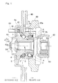
Fig. 1 is a sectional view showing a wheel support bearing assembly according to a first preferred embodiment of the present invention; -
Fig. 2 is a fragmentary enlarged sectional view showing an outer member of the wheel support bearing assembly inFig. 1 ; -
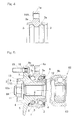
Fig. 3 is a sectional view showing a wheel support bearing assembly according to a second preferred embodiment of the present invention; -
Fig. 4 is a fragmentary enlarged sectional view showing the outer member of the wheel support bearing assembly inFig. 3 ; -
Fig. 5 is a sectional view showing a wheel support bearing assembly according to a third preferred embodiment of the present invention; -
Fig. 6 is a sectional view showing a wheel support bearing assembly according to a fourth preferred embodiment of the present invention; -
Fig. 7 is a sectional view showing a wheel support bearing assembly according to a fifth preferred embodiment of the present invention; -
Fig. 8 is a sectional view showing a wheel support bearing assembly according to a sixth preferred embodiment of the present invention; -
Fig. 9 is a sectional view showing a wheel support bearing assembly according to a seventh preferred embodiment of the present invention; -
Fig. 10 is a sectional view showing a wheel support bearing assembly according to an eighth preferred embodiment of the present invention; andFig. 11 is a chart showing results of the Charpy impact test. -
- 1:
- Outer member
- 1a:
- Vehicle body fitting flange
- 1aa:
- Turned surface
- 2:
- Inner member
- 3, 4:
- Raceway surface
- 3a:
- Hardened layer
- 5:
- Rolling element
- 14:
- Bolt insertion hole
- 14A:
- Female screw hole
- 61:
- Knuckle bolt (Vehicle body fastening bolt)
- A first preferred embodiment of the present invention will be described in detail with particular reference to
Figs. 1 and2 . The wheel support bearing assembly according to this embodiment is a double row angular contact bearing model for use in an automotive vehicle, which is classified as a third generation type, and is an inner ring rotating type for supporting a vehicle drive wheel. It is to be noted that hereinafter in this specification, terms "outboard" and "inboard" represent one side of the vehicle body away from the longitudinal center of the vehicle body and the other side of the vehicle body close to the longitudinal center of the vehicle body, respectively, when assembled in the vehicle body. - This wheel support bearing assembly includes, as best shown in
Fig. 1 in a sectional representation, an outer member I having an inner periphery formed with a plurality of rows ofraceway surfaces 3, aninner member 2 having an outer periphery formed withraceway surfaces 4 aligned with therespective raceway surfaces 3, and a plurality of rows of rollingelements 5 interposed between the raceway surfaces 3 in theouter member 1 and the raceway surfaces 4 in theinner member 2. The rollingelements 5 are in the form of balls and are retained by aretainer 6 employed for each row. The raceway surfaces 3 and 4 referred to above have an arcuate shape in cross-section and are so formed as to represent respective rolling element contact angles that are held in back-to-back relation with each other. Opposite open ends of an annular bearing space delimited between theouter member 1 and theinner member 2 are sealed respectively by outboard andinboard sealing units - The
outer member 1 forms a stationary member and is of one piece construction having an outer periphery formed with a vehiclebody fitting flange 1a that is secured to aknuckle 60 forming a part of the automobile suspension system (not shown). Theflange 1a is provided with vehicle body fitting bolt insertion holes 14 at a plurality of locations spaced in a direction circumferentially thereof, and thisflange 1a is bolted to theknuckle 60 by passingrespective knuckle bolts 61, which are vehicle body fastening bolts, through the bolt insertion holes 14 from the outboard side and are then firmly engaged in respectivefemale screw holes 60a defined in theknuckle 60. - The
inner member 2 forms a rotatable member and includes ahub axle 9 having an outer periphery formed with a wheel mountinghub flange 9a, and aninner ring 10 mounted on an outer periphery of an inboard end of a shank portion or anaxle portion 9b of thehub axle 9. The raceway surfaces 4 one for each row are formed in thehub axle 9 and theinner ring 10, respectively. The inboard end of thehub axle 9 has its outer periphery provided with an inner ring mountingsurface area 12 which is radially inwardly stepped to have a small diameter, and theinner ring 10 is mounted on this inner ring mountingsurface area 12. Thehub axle 9 has a center portion formed with a throughhole 11 defined therein. When astem portion 63a of anouter ring 63 of a constant velocityuniversal joint 62 is inserted into thisthroughhole 11 and, then, theinner member 2 is clamped between a stepped face of thestem portion 63 adjacent a base end thereof and anut 64 threaded onto a free end, the wheel support bearing assembly and the constant velocity universal joint 62 are connected together. Thehub flange 9a is provided with a press-fit hole 16 defined at a plurality of circumferential locations thereof for receiving therein arespective hub bolt 15. At a root portion of thehub flange 9a of thehub axle 9, acylindrical pilot portion 13 for guiding abrake rotor 40 and a vehicle wheel (not shown) protrudes towards the outboard side. By the guidance of thepilot portion 13, thebrake rotor 40 and the vehicle wheel are overlapped to thehub flange 9a and are then fixed in position by thehub bolts 15. - The
outer member 1 is made of a medium carbon steel (C = 0.45 to 0.80 wt% and, preferably, 0.50 to 0.65 wt%) such as, for example, S53C, or a steel material having a chemical composition corresponding to the medium carbon steel and is thermally refined by means of a quenching treatment and a high temperature tempering process. This thermal refinement is carried out subsequent to the hot forging and is followed by turning. By the thermal refinement, a layer of at least 2 mm in depth from a surface of theouter member 1, then rendered to be a product, is sufficiently hardened to form a complete martensite structure and is subsequently rendered to be a micro-pearlitc structure by means of the high temperature tempering process. In other words, the layer of at least 2 mm in depth from the surface of theouter member 1 rendered to be the product has no structure, mixed therein, other than the micro-pearlite structure which is a thermally refined structure. - After the turning, an induction heat treatment or induction hardening is carried out to each of the raceway surfaces 3 of the
outer member 1 over a predetermined depth that is required, to thereby form ahardened layer 3a of a predetermined depth in each of the raceway surfaces 3. Thishardened layer 3a in each of the raceway surfaces 3 has a hardness within the range of 58 to 64 HRC and any other portion of theouter member 1 than thoseraceway surfaces 3 has a hardness within the range of 15 to 35 HRC. In order that the tensile strength and the impact resistance and the turning capability of theouter member 1 as a product can be compatible with each other, that portion of theouter member 1 other than the raceway surfaces 3 has the hardness preferably within the range of 20 to 30 HRC and more preferably within the range of 20 to 25 HRC. - According to the wheel support bearing assembly of the construction described hereinabove, since the
outer member 1 forming the stationary member is thermally refined by means of the quenching treatment and the high temperature tempering process, the toughness of theouter member 1, particularly that exhibited at a low temperature, can be increased. As a result, the resistance characteristic to the impact load can be increased. In other words, the load leading to impairment against the impact load can be increased. In this way, in the event that the automotive vehicle skids and lateral side or vehicle wheels thereof shockingly collide sidewise against the curbside, even though the impact load is loaded on the wheel support bearing assembly, failure of the automotive vehicle to run with the wheel support bearing assembly in its entirety separated from the automotive body structure and the possibility of the vehicle wheel separated and then rolling to collide against an external object can be avoided. -
Figs. 3 and4 illustrate a second preferred embodiment of the present invention. In this second embodiment, an inboard end of theshank portion 9b of thehub axle 9 in the wheel support bearing assembly of the structure shown and described with reference toFigs. 1 and2 in connection with the first embodiment is formed with a crimped portion 9ba for fixedly crimping theinner ring 10. By clamping theinner member 2 together with this crimped portion 9ba between thenut 64, threadingly mounted on thestem portion 63a tip of theouter ring 63 of the constant velocityuniversal joint 62, and a cup portion of the constant velocityuniversal joint 62, the wheel support bearing assembly and the constant velocity universal joint 62 are connected together. - Also, in this embodiment, female screw holes 14A are provided at a plurality of circumferential locations of the vehicle
body fitting flange 1a of theouter member 1 and, by threadingknuckle bolts 61, which are vehicle body fastening bolts inserted from the inboard side through respectivebolt insertion holes 60b in theknuckle 60, into the corresponding female screw holes 14A in theflange 1a, theflange 1a is bolted to theknuckle 60. Thehub flange 9a is provided with abolt insertion hole 16A defined at a plurality of circumferential locations for the hub bolt (not shown). By threading the hub bolts from the outboard side into the respectivebolt insertion holes 16A, thebrake rotor 40 and the vehicle wheel overlapped to thehub flange 9a are fixed to thehub flange 9a. Other structural features are generally similar to those shown in and described with particular reference toFigs. 1 and2 in connection with the first embodiment of the present invention and the details are not therefore reiterated. -
Fig. 5 illustrates a third preferred embodiment of the present invention. In this third embodiment, vehicle body fittingfemale screw holes 14A are defined at a plurality of circumferential locations of the vehiclebody fitting flange 1a of theouter member 1 described as employed in the wheel support bearing assembly according to the first embodiment shown inFigs. 1 and2 , and by threading the knuckle bolts (not shown), which are vehicle body fastening bolts inserted from the inboard side through respective bolt insertion holes (not shown) in the knuckle (not shown), into the corresponding female screw holes 14A in theflange 1a. theflange 1a is bolted to the knuckle. Other structural features are generally similar to those shown in and described with particular reference toFigs. 1 and2 in connection with the first embodiment of the present invention. -
Fig. 6 illustrates a fourth preferred embodiment of the present invention. The wheel support bearing assembly according to this fourth embodiment is a double row angular contact ball bearing model, which is classified as a fourth generation type, and is an inner ring rotating type for supporting a vehicle drive wheel. Theinner member 2 includes thehub axle 9 and theouter ring 63 of the constant velocity universal joint 62 that is inserted into and engaged in the throughhole 11 in thehub axle 9, and the plurality of the rows of the raceway surfaces 4 that are opposed to the raceway surfaces 3 of theouter member 1 are formed respectively in thehub axle 9 and the stem portion of the constant velocity universal jointouter ring 63. Thehub axle 9 is connected with the constant velocity universal jointouter ring 63 by means of a diametric expansion crimping of the stem portion of the constant velocity universal joint 63 that is rendered to be in the form of a hollow shaft. Also, theinboard sealing unit 8 is interposed between an inner diametric surface of theouter member 1 and an outer diametric surface of the constant velocity universal jointouter ring 63. Vehicle body fittingfemale screw holes 14A are defined at a plurality of circumferential locations of the vehiclebody fitting flange 1a of theouter member 1, and by threading the knuckle bolts (not shown), which are vehicle body fastening bolts inserted from the inboard side through respective bolt insertion holes (not shown) in the knuckle (not shown), into the corresponding female screw holes 14A in theflange 1a, theflange 1a is bolted to the knuckle. Other structural features are generally similar to those shown in and described with particular reference toFigs. 1 and2 in connection with the first embodiment of the present invention. -
Fig. 7 illustrates a fifth preferred embodiment of the present invention. The wheel support bearing assembly according to this fifth embodiment is a double row angular contact ball bearing model, which is classified as a second generation type, and is an inner ring rotating type for supporting a vehicle drive wheel. Theinner member 2, which forms the rotatable member, includes ahub axle 9 and two rows ofinner rings shank portion 9b of thehub axle 9 in axially juxtaposed relation to each other. The rows of the raceway surfaces 4 are formed respectively on outer peripheries of the two rows of theinner rings Figs. 1 and2 in connection with the first embodiment of the present invention. -
Fig. 8 illustrates a sixth preferred embodiment of the present invention. The wheel support bearing assembly according to this sixth embodiment is a double row tapered roller bearing model, which is classified as a second generation type, and is an inner ring rotating type for the support of a vehicle drive wheel. This wheel support bearing assembly is similar to that according to the fifth embodiment shown in and described with particular reference toFig. 7 , but differs therefrom in that the balls, forming the rollingelements 5, are replaced with tapered rollers. Also, even in this embodiment, bolt insertion holes 14 for bolting theflange 1a from the outboard side to the knuckle (not shown) are provided in the vehiclebody fitting flange 1a of theouter member 1, but a side surface of theflange 1a oriented towards the outboard side is provided with a turned surface 1aa which defines a seat surface for the knuckle bolt (not shown). In place of the turned surface 1aa, a portion that defines the seat surface may be rendered to be a countersunken surface. The countersinking process to form the countersunken surface is one of cutting techniques. InFig. 8 , the constant velocity universal jointouter ring 63 shown inFig. 7 is not illustrated, but other structural features are similar to those employed in the fifth embodiment shown in and described with particular reference toFig. 7 . -
Fig. 9 illustrates a seventh preferred embodiment of the present invention. This wheel support bearing assembly according to the seventh embodiment is similar to that according to the sixth embodiment shown in and described with particular reference toFig. 8 , but differs therefrom in that a crimped portion 9ba for fixedly crimping theinner rings shank portion 9b of thehub axle 9 is formed. Also, in this embodiment, the vehicle body fitting female screw holes 14A are provided at a plurality of circumferential locations of the vehiclebody fitting flange 1a of theouter member 1, and by threading the knuckle bolts (not shown), which are vehicle body fastening bolts inserted from the inboard side through respective bolt insertion holes (not shown) in the knuckle (not shown), into the corresponding female screw holes 14A in theflange 1a, theflange 1a is bolted to the knuckle. Other structural features are generally similar to those shown in and described with particular reference toFig. 8 in connection with the sixth embodiment of the present invention. -
Fig. 10 illustrates an eighth preferred embodiment of the present invention. The wheel support bearing assembly according to this eighth embodiment is a double row angular contact ball bearing model that is classified as a third generation type, and is an inner rotating type for the support of a vehicle driven wheel. Theinner member 2, forming the rotatable member, includes ahub axle 9 having thewheel mounting flange 9a, and aninner ring 10 mounted on the outer periphery of the inboard end of theshank portion 9b of thehub axle 9, and a crimped portion 9ba for fixedly crimping theinner ring 10 is formed in the inboard end of theshank portion 9b of thehub axle 9. Thehub ring 9 is of a solid structure and has no throughhole such as thethroughhole 11 employed in the second embodiment shown inFig. 3 , and the constant velocity universal joint outer ring is not connected to the wheel support bearing assembly. Other structural features are similar to those employed in the second embodiment shown in and described with particular reference toFigs. 3 and4 . - Although the present invention has been fully described in connection with the preferred embodiments thereof with reference to the accompanying drawings which are used only for the purpose of illustration, those skilled in the art will readily conceive numerous changes and modifications within the framework of obviousness upon the reading of the specification herein presented of the present invention.
- Accordingly, such changes and modifications are, unless they depart from the scope of the present invention as delivered from the claims annexed hereto, to be construed as included therein.
Claims (7)
- A wheel support bearing assembly for rotatably supporting a vehicle wheel relative to a vehicle body structure, which comprises:an outer member, which serves as a stationary member and has an inner periphery formed with a plurality of rows of raceway surfaces;an inner member, which serves as a rotatable member and has an outer periphery formed with respective raceway surfaces opposed to the previously described raceway surfaces;a plurality of rows of rolling elements interposed between the respective opposed raceway surfaces;in which the outer member is thermally refined by quenching and high temperature tempering such that a layer of at least 2 mm in depth from a surface of the outer member is rendered to have a micro-pearlite structure.
- The wheel support bearing assembly as claimed in claim 1, in which the outer member has the outer periphery provided with a vehicle body fitting flange, which has female screw holes defined therein for bolting from an inboard side to the vehicle body structure.
- The wheel support bearing assembly as claimed in claim 1, in which the outer member has the outer periphery provided with a vehicle body fitting flange, which has bolt insertion holes defined therein for bolting from an outboard to the vehicle body structure and a turned surface or a countersunken surface which defines a seat surface of a vehicle body fastening bolt.
- The wheel support bearing assembly as claimed in claim 1, in which the outer member is made of medium carbon steel or a steel material having a chemical composition corresponding to the medium carbon steel and has the raceway surfaces hardened over a predetermined depth by means of an induction hardening which is effected after turning following the thermal refinement that has been performed subsequent to the hot forging.
- The wheel support bearing assembly as claimed in claim 4, in which the raceway surfaces of the outer member has a hardness within the range of 58 to 64 HRC and the other portion of the outer member has a hardness within the range of 15 to 35 HRC.
- The wheel support bearing assembly as claimed in claim 1, in which the rolling elements are in the form of balls.
- The wheel support bearing assembly as claimed in claim 1, in which the rolling elements are in the form of tapered rollers.
Applications Claiming Priority (2)
| Application Number | Priority Date | Filing Date | Title |
|---|---|---|---|
| JP2008031847A JP5288821B2 (en) | 2008-02-13 | 2008-02-13 | Wheel bearing device |
| PCT/JP2009/000457 WO2009101777A1 (en) | 2008-02-13 | 2009-02-06 | Automotive bearing device |
Publications (3)
| Publication Number | Publication Date |
|---|---|
| EP2248680A1 true EP2248680A1 (en) | 2010-11-10 |
| EP2248680A4 EP2248680A4 (en) | 2011-03-02 |
| EP2248680B1 EP2248680B1 (en) | 2011-11-09 |
Family
ID=40956812
Family Applications (1)
| Application Number | Title | Priority Date | Filing Date |
|---|---|---|---|
| EP09710042A Not-in-force EP2248680B1 (en) | 2008-02-13 | 2009-02-06 | Automotive bearing device |
Country Status (5)
| Country | Link |
|---|---|
| US (1) | US8215846B2 (en) |
| EP (1) | EP2248680B1 (en) |
| JP (1) | JP5288821B2 (en) |
| AT (1) | ATE532648T1 (en) |
| WO (1) | WO2009101777A1 (en) |
Families Citing this family (5)
| Publication number | Priority date | Publication date | Assignee | Title |
|---|---|---|---|---|
| JP5183358B2 (en) * | 2008-08-22 | 2013-04-17 | Ntn株式会社 | Wheel bearing device |
| ITTO20111127A1 (en) * | 2011-12-09 | 2013-06-10 | Skf Ab | INTEGRATED BEARING-HUB ASSEMBLY FOR THE WHEEL OF A MOTOR VEHICLE |
| JP5820842B2 (en) * | 2013-05-08 | 2015-11-24 | 富士重工業株式会社 | Wheel reaction force detection device |
| JP6167836B2 (en) * | 2013-10-15 | 2017-07-26 | 日本精工株式会社 | Wheel support hub unit |
| JP7079582B2 (en) * | 2016-09-21 | 2022-06-02 | Ntn株式会社 | Wheel bearing device with auxiliary power unit and its auxiliary power unit |
Family Cites Families (17)
| Publication number | Priority date | Publication date | Assignee | Title |
|---|---|---|---|---|
| US6287009B1 (en) * | 1998-03-06 | 2001-09-11 | Nsk Ltd. | Rolling bearing unit with rotation speed detection instrument for use in cars and method for working outer race for use in this bearing unit |
| JP2004156764A (en) * | 2002-08-29 | 2004-06-03 | Nsk Ltd | Bearing device with flange and method of manufacturing the device |
| JP4151467B2 (en) | 2003-04-17 | 2008-09-17 | 日本精工株式会社 | Rolling bearing unit for wheel support |
| JP2005067430A (en) * | 2003-08-26 | 2005-03-17 | Nsk Ltd | Rolling bearing unit for wheel support |
| JP2005256897A (en) * | 2004-03-10 | 2005-09-22 | Ntn Corp | Machine element and its manufacturing method |
| JP2005308152A (en) | 2004-04-23 | 2005-11-04 | Nsk Ltd | Wheel support bearing device |
| JP2006064036A (en) * | 2004-08-25 | 2006-03-09 | Nsk Ltd | Wheel support bearing device |
| JP2006132751A (en) * | 2004-11-09 | 2006-05-25 | Ntn Corp | Self-aligning roller bearing |
| JP2006241559A (en) * | 2005-03-04 | 2006-09-14 | Nsk Ltd | Rolling bearing unit for wheel support |
| JP2006291250A (en) | 2005-04-06 | 2006-10-26 | Nsk Ltd | Rolling bearing unit for wheel support |
| JP2006328464A (en) * | 2005-05-25 | 2006-12-07 | Nsk Ltd | Rolling bearing and method of manufacturing rolling parts thereof |
| JP2006329287A (en) * | 2005-05-25 | 2006-12-07 | Nsk Ltd | Rolling bearing unit for wheel support and method for manufacturing the inner ring |
| JP2006342902A (en) * | 2005-06-09 | 2006-12-21 | Nsk Ltd | Rolling bearing unit for wheel support and method for manufacturing the outer ring |
| JP5019727B2 (en) * | 2005-07-20 | 2012-09-05 | Ntn株式会社 | Wheel bearing device |
| WO2007010772A1 (en) * | 2005-07-20 | 2007-01-25 | Ntn Corporation | Bearing device for wheel |
| JP5105728B2 (en) * | 2005-08-19 | 2012-12-26 | Ntn株式会社 | Wheel bearing device |
| JP2007107647A (en) * | 2005-10-14 | 2007-04-26 | Nsk Ltd | Rolling bearing device for wheel support |
-
2008
- 2008-02-13 JP JP2008031847A patent/JP5288821B2/en not_active Expired - Fee Related
-
2009
- 2009-02-06 WO PCT/JP2009/000457 patent/WO2009101777A1/en not_active Ceased
- 2009-02-06 US US12/735,706 patent/US8215846B2/en not_active Expired - Fee Related
- 2009-02-06 EP EP09710042A patent/EP2248680B1/en not_active Not-in-force
- 2009-02-06 AT AT09710042T patent/ATE532648T1/en active
Also Published As
| Publication number | Publication date |
|---|---|
| WO2009101777A1 (en) | 2009-08-20 |
| JP5288821B2 (en) | 2013-09-11 |
| US20100316319A1 (en) | 2010-12-16 |
| US8215846B2 (en) | 2012-07-10 |
| EP2248680A4 (en) | 2011-03-02 |
| EP2248680B1 (en) | 2011-11-09 |
| ATE532648T1 (en) | 2011-11-15 |
| JP2009191912A (en) | 2009-08-27 |
Similar Documents
| Publication | Publication Date | Title |
|---|---|---|
| JP4063722B2 (en) | Wheel bearing device | |
| US8714829B2 (en) | Wheel bearing assembly | |
| EP2908019B1 (en) | Manufacturing method for bearing device for wheel | |
| EP2248680B1 (en) | Automotive bearing device | |
| JP5235313B2 (en) | Wheel bearing device | |
| US20090106980A1 (en) | Process for Producing Bearing Device for Wheel | |
| US7147381B2 (en) | Wheel support bearing assembly | |
| US8162545B2 (en) | Hub unit | |
| US20090129717A1 (en) | Bearing Device for Wheel | |
| JP2008275023A (en) | Hub unit bearing | |
| JP5147259B2 (en) | Manufacturing method of wheel bearing device | |
| JP2007211987A (en) | Wheel bearing device and method for manufacturing same | |
| JP5415999B2 (en) | Wheel bearing device | |
| EP2113394A1 (en) | Bearing for wheel and method for manufacturing the same | |
| JP5105727B2 (en) | Wheel bearing device | |
| JP5105728B2 (en) | Wheel bearing device | |
| JP5175055B2 (en) | Wheel bearing device | |
| JP5235314B2 (en) | Wheel bearing device | |
| JP5025925B2 (en) | Wheel bearing device | |
| JP4471283B2 (en) | Wheel bearing device | |
| JP2004183815A (en) | Bearing device for wheel | |
| JP5142553B2 (en) | Wheel bearing device | |
| JP2008207600A (en) | Wheel bearing device | |
| JP2005308152A (en) | Wheel support bearing device | |
| JP2009220795A (en) | Wheel supporting rolling bearing unit, and its manufacturing method |
Legal Events
| Date | Code | Title | Description |
|---|---|---|---|
| PUAI | Public reference made under article 153(3) epc to a published international application that has entered the european phase |
Free format text: ORIGINAL CODE: 0009012 |
|
| 17P | Request for examination filed |
Effective date: 20100827 |
|
| AK | Designated contracting states |
Kind code of ref document: A1 Designated state(s): AT BE BG CH CY CZ DE DK EE ES FI FR GB GR HR HU IE IS IT LI LT LU LV MC MK MT NL NO PL PT RO SE SI SK TR |
|
| AX | Request for extension of the european patent |
Extension state: AL BA RS |
|
| A4 | Supplementary search report drawn up and despatched |
Effective date: 20110131 |
|
| RIC1 | Information provided on ipc code assigned before grant |
Ipc: B60B 35/18 20060101AFI20110401BHEP Ipc: F16C 33/62 20060101ALI20110401BHEP Ipc: F16C 19/18 20060101ALI20110401BHEP Ipc: B60B 35/14 20060101ALI20110401BHEP Ipc: B60B 35/02 20060101ALI20110401BHEP |
|
| GRAP | Despatch of communication of intention to grant a patent |
Free format text: ORIGINAL CODE: EPIDOSNIGR1 |
|
| DAX | Request for extension of the european patent (deleted) | ||
| GRAS | Grant fee paid |
Free format text: ORIGINAL CODE: EPIDOSNIGR3 |
|
| GRAA | (expected) grant |
Free format text: ORIGINAL CODE: 0009210 |
|
| AK | Designated contracting states |
Kind code of ref document: B1 Designated state(s): AT BE BG CH CY CZ DE DK EE ES FI FR GB GR HR HU IE IS IT LI LT LU LV MC MK MT NL NO PL PT RO SE SI SK TR |
|
| REG | Reference to a national code |
Ref country code: GB Ref legal event code: FG4D |
|
| REG | Reference to a national code |
Ref country code: CH Ref legal event code: EP |
|
| REG | Reference to a national code |
Ref country code: IE Ref legal event code: FG4D |
|
| REG | Reference to a national code |
Ref country code: DE Ref legal event code: R096 Ref document number: 602009003608 Country of ref document: DE Effective date: 20120105 |
|
| REG | Reference to a national code |
Ref country code: NL Ref legal event code: VDEP Effective date: 20111109 |
|
| LTIE | Lt: invalidation of european patent or patent extension |
Effective date: 20111109 |
|
| PG25 | Lapsed in a contracting state [announced via postgrant information from national office to epo] |
Ref country code: LT Free format text: LAPSE BECAUSE OF FAILURE TO SUBMIT A TRANSLATION OF THE DESCRIPTION OR TO PAY THE FEE WITHIN THE PRESCRIBED TIME-LIMIT Effective date: 20111109 Ref country code: NO Free format text: LAPSE BECAUSE OF FAILURE TO SUBMIT A TRANSLATION OF THE DESCRIPTION OR TO PAY THE FEE WITHIN THE PRESCRIBED TIME-LIMIT Effective date: 20120209 Ref country code: IS Free format text: LAPSE BECAUSE OF FAILURE TO SUBMIT A TRANSLATION OF THE DESCRIPTION OR TO PAY THE FEE WITHIN THE PRESCRIBED TIME-LIMIT Effective date: 20120309 |
|
| PG25 | Lapsed in a contracting state [announced via postgrant information from national office to epo] |
Ref country code: NL Free format text: LAPSE BECAUSE OF FAILURE TO SUBMIT A TRANSLATION OF THE DESCRIPTION OR TO PAY THE FEE WITHIN THE PRESCRIBED TIME-LIMIT Effective date: 20111109 Ref country code: BE Free format text: LAPSE BECAUSE OF FAILURE TO SUBMIT A TRANSLATION OF THE DESCRIPTION OR TO PAY THE FEE WITHIN THE PRESCRIBED TIME-LIMIT Effective date: 20111109 Ref country code: PL Free format text: LAPSE BECAUSE OF FAILURE TO SUBMIT A TRANSLATION OF THE DESCRIPTION OR TO PAY THE FEE WITHIN THE PRESCRIBED TIME-LIMIT Effective date: 20111109 Ref country code: SI Free format text: LAPSE BECAUSE OF FAILURE TO SUBMIT A TRANSLATION OF THE DESCRIPTION OR TO PAY THE FEE WITHIN THE PRESCRIBED TIME-LIMIT Effective date: 20111109 Ref country code: LV Free format text: LAPSE BECAUSE OF FAILURE TO SUBMIT A TRANSLATION OF THE DESCRIPTION OR TO PAY THE FEE WITHIN THE PRESCRIBED TIME-LIMIT Effective date: 20111109 Ref country code: PT Free format text: LAPSE BECAUSE OF FAILURE TO SUBMIT A TRANSLATION OF THE DESCRIPTION OR TO PAY THE FEE WITHIN THE PRESCRIBED TIME-LIMIT Effective date: 20120309 Ref country code: HR Free format text: LAPSE BECAUSE OF FAILURE TO SUBMIT A TRANSLATION OF THE DESCRIPTION OR TO PAY THE FEE WITHIN THE PRESCRIBED TIME-LIMIT Effective date: 20111109 Ref country code: GR Free format text: LAPSE BECAUSE OF FAILURE TO SUBMIT A TRANSLATION OF THE DESCRIPTION OR TO PAY THE FEE WITHIN THE PRESCRIBED TIME-LIMIT Effective date: 20120210 Ref country code: SE Free format text: LAPSE BECAUSE OF FAILURE TO SUBMIT A TRANSLATION OF THE DESCRIPTION OR TO PAY THE FEE WITHIN THE PRESCRIBED TIME-LIMIT Effective date: 20111109 |
|
| PG25 | Lapsed in a contracting state [announced via postgrant information from national office to epo] |
Ref country code: CY Free format text: LAPSE BECAUSE OF FAILURE TO SUBMIT A TRANSLATION OF THE DESCRIPTION OR TO PAY THE FEE WITHIN THE PRESCRIBED TIME-LIMIT Effective date: 20111109 |
|
| PG25 | Lapsed in a contracting state [announced via postgrant information from national office to epo] |
Ref country code: DK Free format text: LAPSE BECAUSE OF FAILURE TO SUBMIT A TRANSLATION OF THE DESCRIPTION OR TO PAY THE FEE WITHIN THE PRESCRIBED TIME-LIMIT Effective date: 20111109 Ref country code: SK Free format text: LAPSE BECAUSE OF FAILURE TO SUBMIT A TRANSLATION OF THE DESCRIPTION OR TO PAY THE FEE WITHIN THE PRESCRIBED TIME-LIMIT Effective date: 20111109 Ref country code: CZ Free format text: LAPSE BECAUSE OF FAILURE TO SUBMIT A TRANSLATION OF THE DESCRIPTION OR TO PAY THE FEE WITHIN THE PRESCRIBED TIME-LIMIT Effective date: 20111109 Ref country code: EE Free format text: LAPSE BECAUSE OF FAILURE TO SUBMIT A TRANSLATION OF THE DESCRIPTION OR TO PAY THE FEE WITHIN THE PRESCRIBED TIME-LIMIT Effective date: 20111109 Ref country code: BG Free format text: LAPSE BECAUSE OF FAILURE TO SUBMIT A TRANSLATION OF THE DESCRIPTION OR TO PAY THE FEE WITHIN THE PRESCRIBED TIME-LIMIT Effective date: 20120209 |
|
| PG25 | Lapsed in a contracting state [announced via postgrant information from national office to epo] |
Ref country code: RO Free format text: LAPSE BECAUSE OF FAILURE TO SUBMIT A TRANSLATION OF THE DESCRIPTION OR TO PAY THE FEE WITHIN THE PRESCRIBED TIME-LIMIT Effective date: 20111109 Ref country code: IT Free format text: LAPSE BECAUSE OF FAILURE TO SUBMIT A TRANSLATION OF THE DESCRIPTION OR TO PAY THE FEE WITHIN THE PRESCRIBED TIME-LIMIT Effective date: 20111109 |
|
| PLBE | No opposition filed within time limit |
Free format text: ORIGINAL CODE: 0009261 |
|
| STAA | Information on the status of an ep patent application or granted ep patent |
Free format text: STATUS: NO OPPOSITION FILED WITHIN TIME LIMIT |
|
| REG | Reference to a national code |
Ref country code: AT Ref legal event code: MK05 Ref document number: 532648 Country of ref document: AT Kind code of ref document: T Effective date: 20111109 |
|
| PG25 | Lapsed in a contracting state [announced via postgrant information from national office to epo] |
Ref country code: MC Free format text: LAPSE BECAUSE OF NON-PAYMENT OF DUE FEES Effective date: 20120229 |
|
| 26N | No opposition filed |
Effective date: 20120810 |
|
| REG | Reference to a national code |
Ref country code: IE Ref legal event code: MM4A |
|
| REG | Reference to a national code |
Ref country code: DE Ref legal event code: R097 Ref document number: 602009003608 Country of ref document: DE Effective date: 20120810 |
|
| PG25 | Lapsed in a contracting state [announced via postgrant information from national office to epo] |
Ref country code: AT Free format text: LAPSE BECAUSE OF FAILURE TO SUBMIT A TRANSLATION OF THE DESCRIPTION OR TO PAY THE FEE WITHIN THE PRESCRIBED TIME-LIMIT Effective date: 20111109 Ref country code: IE Free format text: LAPSE BECAUSE OF NON-PAYMENT OF DUE FEES Effective date: 20120206 |
|
| PG25 | Lapsed in a contracting state [announced via postgrant information from national office to epo] |
Ref country code: MK Free format text: LAPSE BECAUSE OF FAILURE TO SUBMIT A TRANSLATION OF THE DESCRIPTION OR TO PAY THE FEE WITHIN THE PRESCRIBED TIME-LIMIT Effective date: 20111109 |
|
| PG25 | Lapsed in a contracting state [announced via postgrant information from national office to epo] |
Ref country code: ES Free format text: LAPSE BECAUSE OF FAILURE TO SUBMIT A TRANSLATION OF THE DESCRIPTION OR TO PAY THE FEE WITHIN THE PRESCRIBED TIME-LIMIT Effective date: 20120220 |
|
| PG25 | Lapsed in a contracting state [announced via postgrant information from national office to epo] |
Ref country code: FI Free format text: LAPSE BECAUSE OF FAILURE TO SUBMIT A TRANSLATION OF THE DESCRIPTION OR TO PAY THE FEE WITHIN THE PRESCRIBED TIME-LIMIT Effective date: 20111109 |
|
| PG25 | Lapsed in a contracting state [announced via postgrant information from national office to epo] |
Ref country code: MT Free format text: LAPSE BECAUSE OF FAILURE TO SUBMIT A TRANSLATION OF THE DESCRIPTION OR TO PAY THE FEE WITHIN THE PRESCRIBED TIME-LIMIT Effective date: 20111109 |
|
| REG | Reference to a national code |
Ref country code: CH Ref legal event code: PL |
|
| GBPC | Gb: european patent ceased through non-payment of renewal fee |
Effective date: 20130206 |
|
| PG25 | Lapsed in a contracting state [announced via postgrant information from national office to epo] |
Ref country code: LI Free format text: LAPSE BECAUSE OF NON-PAYMENT OF DUE FEES Effective date: 20130228 Ref country code: CH Free format text: LAPSE BECAUSE OF NON-PAYMENT OF DUE FEES Effective date: 20130228 |
|
| PG25 | Lapsed in a contracting state [announced via postgrant information from national office to epo] |
Ref country code: GB Free format text: LAPSE BECAUSE OF NON-PAYMENT OF DUE FEES Effective date: 20130206 |
|
| PG25 | Lapsed in a contracting state [announced via postgrant information from national office to epo] |
Ref country code: TR Free format text: LAPSE BECAUSE OF FAILURE TO SUBMIT A TRANSLATION OF THE DESCRIPTION OR TO PAY THE FEE WITHIN THE PRESCRIBED TIME-LIMIT Effective date: 20111109 |
|
| PG25 | Lapsed in a contracting state [announced via postgrant information from national office to epo] |
Ref country code: LU Free format text: LAPSE BECAUSE OF NON-PAYMENT OF DUE FEES Effective date: 20120206 |
|
| PG25 | Lapsed in a contracting state [announced via postgrant information from national office to epo] |
Ref country code: HU Free format text: LAPSE BECAUSE OF FAILURE TO SUBMIT A TRANSLATION OF THE DESCRIPTION OR TO PAY THE FEE WITHIN THE PRESCRIBED TIME-LIMIT Effective date: 20090206 |
|
| REG | Reference to a national code |
Ref country code: FR Ref legal event code: PLFP Year of fee payment: 8 |
|
| REG | Reference to a national code |
Ref country code: FR Ref legal event code: PLFP Year of fee payment: 9 |
|
| REG | Reference to a national code |
Ref country code: FR Ref legal event code: PLFP Year of fee payment: 10 |
|
| PGFP | Annual fee paid to national office [announced via postgrant information from national office to epo] |
Ref country code: DE Payment date: 20190122 Year of fee payment: 11 Ref country code: FR Payment date: 20190111 Year of fee payment: 11 |
|
| REG | Reference to a national code |
Ref country code: DE Ref legal event code: R119 Ref document number: 602009003608 Country of ref document: DE |
|
| PG25 | Lapsed in a contracting state [announced via postgrant information from national office to epo] |
Ref country code: DE Free format text: LAPSE BECAUSE OF NON-PAYMENT OF DUE FEES Effective date: 20200901 Ref country code: FR Free format text: LAPSE BECAUSE OF NON-PAYMENT OF DUE FEES Effective date: 20200229 |