EP2248591A2 - Device and method for emptying grinding bodies from a grinding container - Google Patents
Device and method for emptying grinding bodies from a grinding container Download PDFInfo
- Publication number
- EP2248591A2 EP2248591A2 EP10004666A EP10004666A EP2248591A2 EP 2248591 A2 EP2248591 A2 EP 2248591A2 EP 10004666 A EP10004666 A EP 10004666A EP 10004666 A EP10004666 A EP 10004666A EP 2248591 A2 EP2248591 A2 EP 2248591A2
- Authority
- EP
- European Patent Office
- Prior art keywords
- grinding
- container
- tube
- grinding container
- media
- Prior art date
- Legal status (The legal status is an assumption and is not a legal conclusion. Google has not performed a legal analysis and makes no representation as to the accuracy of the status listed.)
- Withdrawn
Links
Images


Classifications
-
- B—PERFORMING OPERATIONS; TRANSPORTING
- B02—CRUSHING, PULVERISING, OR DISINTEGRATING; PREPARATORY TREATMENT OF GRAIN FOR MILLING
- B02C—CRUSHING, PULVERISING, OR DISINTEGRATING IN GENERAL; MILLING GRAIN
- B02C17/00—Disintegrating by tumbling mills, i.e. mills having a container charged with the material to be disintegrated with or without special disintegrating members such as pebbles or balls
- B02C17/16—Mills in which a fixed container houses stirring means tumbling the charge
- B02C17/161—Arrangements for separating milling media and ground material
-
- B—PERFORMING OPERATIONS; TRANSPORTING
- B02—CRUSHING, PULVERISING, OR DISINTEGRATING; PREPARATORY TREATMENT OF GRAIN FOR MILLING
- B02C—CRUSHING, PULVERISING, OR DISINTEGRATING IN GENERAL; MILLING GRAIN
- B02C17/00—Disintegrating by tumbling mills, i.e. mills having a container charged with the material to be disintegrated with or without special disintegrating members such as pebbles or balls
- B02C17/16—Mills in which a fixed container houses stirring means tumbling the charge
-
- B—PERFORMING OPERATIONS; TRANSPORTING
- B02—CRUSHING, PULVERISING, OR DISINTEGRATING; PREPARATORY TREATMENT OF GRAIN FOR MILLING
- B02C—CRUSHING, PULVERISING, OR DISINTEGRATING IN GENERAL; MILLING GRAIN
- B02C17/00—Disintegrating by tumbling mills, i.e. mills having a container charged with the material to be disintegrated with or without special disintegrating members such as pebbles or balls
- B02C17/18—Details
Definitions
- the need to remove all grinding media from a grinding container exists in many cases, such as when servicing the mill. Another case relates to the change of the material to be treated in the grinding container, if this requires the use of a certain size of grinding media. This also occurs when the product to be treated in the grinding container is to receive a greater or lesser particle fineness than the product currently in the grinding container. In these cases, it is not sufficient that the grinding media, which are used in approximately spherical shape, are only partially removed from the grinding container.
- the object of the invention is therefore to simplify the removal of the grinding media and to shorten the time required for it.
- the interior of the grinding chamber is flowed through by means of a fluid and the grinding bodies are removed from the grinding container by this flow, via an opening positionable along the longitudinal axis of the grinding container.
- the opening for removing the grinding media is placed at the point in the grinding container, are present at the grinding media. Since the fluid flow seeks the shortest path out of the grinding bowl, the fluid only delivers grinding media at the location where the grinding media are positioned directly in front of the opening of a pipe or outlet for the removal of the grinding media.
- the grinding media are removed at horizontally arranged grinding containers at the lowest point, in the lower radius of the grinding container. Since grinding media collect in the grinding container in the lower radius region due to their gravity without actuation of the agitator, their removal at this point is preferred according to the invention.
- the removal of the grinding media and the establishment of a flow in the grinding container, which is connected to the supply of a fluid, preferably takes place in a closed circuit.
- This closed circuit is maintained in order to exclude according to the preferred variant of the invention that air enters the circuit, which can interfere with the drainage process and to keep the amount of rinsing liquid to the total emptying of the grinding chamber low.
- the pressure and the flow thus generated does not act uniformly but pulsatingly on the grinding bodies.
- one or more displaceable or openable outlet openings are / are provided in the lower region of the grinding chamber / grinding container.
- the outlet opening is the beginning of a tube insertable into the grinding container.
- This tube is preferably introduced through the outlet port in the grinding container in the grinding chamber.
- a hollow cylinder can be arranged in the lower radius region in and outside of the grinding container, which has a longitudinal slot in a development of the invention.
- the hollow cylinder here is a tube which is rotatably arranged and has a helical slot.
- the Mahl interchangeerinnenwand or the grinding container on a longitudinal slot or openings which is / is connected to a slotted tube on the outside of the grinding container or on the outside of Mahl arterinnenwand / to the grinding media over the pipe remove.
- the fluid is fed via the Mahl practicereinltru the grinding chamber.
- the inlet for the rinsing agent is not located at the product inlet of the grinding chamber, but in the upper longitudinal region, preferably centrally in the grinding container. In this arrangement, the size or the length of the grinding container is taken into account, so that with longer grinding containers and multiple fluid inlet or existing inlets or outlets can be used.
- a further embodiment relates to the arrangement of a screw conveyor in a tube in the lowermost region of the grinding container.
- the screw conveyor starts at the opening of the tube in the grinding chamber and extends at least the length of the tube in the grinding container.
- the tube can be attached to its center axis of the Grinding container side have a longitudinal slot, get over the grinding media in the screw conveyor.
- the grinding media are flushed out of the grinding bowl and pipe only when the flow rate of the fluid is high enough.
- the flow force results from viscosity, density and flow rate of the flushing fluid.
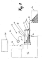
- FIG. 1 shows a schematic representation of a stirred ball mill 10 with a machine stand 12, which receives a drive and a transmission.
- a stirrer shaft In connection with the gearbox is a stirrer shaft, which is not shown for the sake of clarity.
- the stirring shaft is arranged centrally along the longitudinal axis 14 and transmits the power generated by the drive to the grinding media 16, whereby the product contained in the grinding container 18 is comminuted or dispersed.
- the grinding media 14 During servicing and when switching to a new product to be machined, the grinding media 14 must either be completely removed, cleaned, replaced with larger or smaller or another material.
- the grinding container is to empty completely, which is possible with the compositions and methods of the invention.
- FIG. 1 Use a tube 20 which is introduced through the ball outlet 22 in the grinding container 18. If the tube is in the grinding container 18, a pump 24 generates a flow which supplies the fluid from the liquid container 26 via the lines 28, 30 to the grinding container. The flow, which builds up here in the grinding container, presses the grinding media 16 in the tube 20, from where they flow via the line 32 into the collecting container. Depending on the product characteristics, on the design of the stirring tools and the separator, a different distribution form of the grinding media 16 in the grinding container 18 can be set after stopping the agitator. It is therefore necessary that in the region of the opening 38 for removing the grinding media 16 and grinding media 16 are present.
- the tube 20 first picks up grinding media starting from the right-hand side of the grinding container, since here the fluid flow acts directly on the grinding bodies lying directly in front of the opening.
- the liquid always goes the least resistant way to get from the fluid inlet 40, which is centrally located here, to the opening 38.
- the opening 38 of the pipe is displaced in the direction of the longitudinal axis 14 of the grinding container and the degradation of the grinding stock package continues.
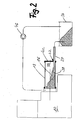
- the same device, namely a pipe 20, for emptying the grinding media 16 from the grinding container 18 provides FIG. 2 Again, pushes the tube 20 via the ball outlet 22 in the grinding container bottom 42 into the grinding chamber 44.
- the ball outlet and thus the tube 20 are arranged here in the lower radius region of the grinding container, where the grinding media collects.
- the fluid water or cleaning fluid constantly flows in a circuit between the grinding container 18 and the collecting container 34.
- FIG. 3 Another variant to extract the grinding media 16 from the grinding container 18, shows FIG. 3 , Here, two concentrically arranged tubes 20, 48 are inserted into the ball outlet 22 of the grinding container bottom 42. Via the outer tube 48, the fluid (rinsing liquid) is supplied. at the inner end of the tube 48 in the grinding container 18, the fluid is deflected and exits through the inner tube 50 again. In this case, the flow of grinding media flushes before the opening of the inner tube 50 from the grinding chamber 44th
- this tube combination is arranged in the grinding container 18, this can also sit outside on the grinding container 18.
- the grinding container 18 would be provided at the bottom with a slot which would also belong to an outer tube at the same time. In this outer tube then along the longitudinal axis 14 movable tube with the opening 38 would be provided.
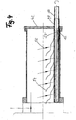
- FIG. 4 An alternative way to relocate the outlet opening provides FIG. 4
- a double-walled tube 48 connected to the grinding vessel bottom 42 extends over the entire length of the grinding container 18.
- the rigid tube 48 has an upwardly directed slot which extends over almost the entire tube length.
- a second fitted rotatable tube 50 In the tube 48 is a second fitted rotatable tube 50.
- This tube 50 has one or more helically extending slots 52, 52 '.
- openings between the grinding chamber and the interior of the tube 50 when the axial slot in the tube 48 coincides with the slot in the tube 50.
- the respective intersection of the openings travels axially along the tubes 48, 50, as illustrated by the curved flow lines 54 and arrows 56.
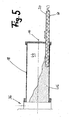
- FIG. 5 shows a variant of the invention, in which for removing the grinding media 16 from the grinding container 18 no fluid flow is needed.
- the tube 20 used here is seated in the lower region of the grinding chamber 44 and is movable along the longitudinal axis of the grinding container 18.
- the opening 38 of the tube 20 is always in the portion of the grinding container in which there are grinding media.
- the Transport of the grinding media 16 from the grinding chamber 44 accomplishes a screw conveyor 60, which is driven by hand or automatically via an electric drive about its longitudinal axis.
- the screw conveyor 60 pulls the grinding media in front of the opening 38 into the tube 20 and discharges it outside of the grinding container 18. Promotes the screw conveyor no more grinding media, so you move the tube in the next portion of the grinding chamber 44th
- FIG. 6 the structure of the pipe combination 48, 50 is shown in perspective form. Due to the helical shape of the slot 52 and the axial extent of the longitudinal slot 62 opens or shifts the opening 64 formed from the slot 52 and the longitudinal slot 62 and allows grinding media flow out of the grinding chamber 44.
- the tube 48 may also be arranged on the underside of the grinding container, wherein then the grinding container is slotted. Likewise, the position of the slot can be changed, which can then be laterally rotated by 90 ° to the longitudinal axis or by 180 °, so that all grinding media flow out of the grinding chamber.
Abstract
Description
Die Notwendigkeit zum Entfernen aller Mahlkörper aus einem Mahlbehälter besteht in vielen Fällen, wie zum Beispiel bei Servicearbeiten an der Mühle. Ein weiterer Fall betrifft den Wechsel des im Mahlbehälter zu behandelnden Gutes, wenn hiermit die Verwendung einer bestimmten Mahlkörpergröße erforderlich ist. Ebenso tritt dies ein, wenn das zu behandelnde Produkt im Mahlbehälter eine größere oder kleinere Partikelfeinheit erhalten soll, als das momentan im Mahlbehälter befindliche Produkt. In diesen Fällen reicht es nicht aus, daß die Mahlkörper, die in annähernd kugelförmiger Form zum Einsatz kommen, nur teilweise aus dem Mahlbehälter entnommen werden.The need to remove all grinding media from a grinding container exists in many cases, such as when servicing the mill. Another case relates to the change of the material to be treated in the grinding container, if this requires the use of a certain size of grinding media. This also occurs when the product to be treated in the grinding container is to receive a greater or lesser particle fineness than the product currently in the grinding container. In these cases, it is not sufficient that the grinding media, which are used in approximately spherical shape, are only partially removed from the grinding container.
Vorrichtungen, die es erlauben einen Teil des im Mahlbehälter befindlichen Mahlkörperpakets aus dem Mahlraum zu entnehmen, gehen aus der deutschen Patentanmeldung
Sollten die Mahlkörper jedoch vollständig aus dem Mahlbehälter entnommen werden, so ließ man bisher einen Teil der Mahlkörper über einen Kugelauslaß im Mahlbehälterboden entweichen und entnahm den Rest nach der Abnahme des Mahlbehälterbodens von Hand.However, if the grinding media are completely removed from the grinding container, it was previously allowed to escape a part of the grinding media via a ball outlet in the bottom of the grinding container and removed the remainder after the removal of the grinding container bottom by hand.
Aufgabe der Erfindung ist es demnach, die Entnahme der Mahlkörper zu vereinfachen und die dafür benötigte Zeit zu verkürzen.The object of the invention is therefore to simplify the removal of the grinding media and to shorten the time required for it.
Die erfindungsgemäße Aufgabe wird durch die Merkmale der Ansprüche 1, 6 und 14 gelöst, Ausgestaltungen der Erfindung gehen aus den Merkmalen der Unteransprüche 2 - 5 sowie 7 - 13 und 15 hervor.The object of the invention is solved by the features of
Entsprechend einer ersten erfindungsgemäßen Verfahrensweise wird der Mahlbehälterinnenraum mittels eines Fluids durchströmt und die Mahlkörper durch diese Strömung, über eine entlang der Längsachse des Mahlbehälters positionierbare Öffnung, aus dem Mahlbehälter entfernt.In accordance with a first method of the invention, the interior of the grinding chamber is flowed through by means of a fluid and the grinding bodies are removed from the grinding container by this flow, via an opening positionable along the longitudinal axis of the grinding container.
Es hat sich gezeigt, daß es von Vorteil ist, wenn die Öffnung zur Entnahme der Mahlkörper an der Stelle im Mahlbehälter plaziert wird, an der Mahlkörper vorhanden sind. Da sich die Fluidströmung den kürzesten Weg aus dem Mahlbehälter sucht, fördert das Fluid nur Mahlkörper an der Stelle, an der die Mahlkörper direkt vor der Öffnung eines Rohres oder Auslasses für die Entnahme der Mahlkörper positioniert sind.It has been found that it is advantageous if the opening for removing the grinding media is placed at the point in the grinding container, are present at the grinding media. Since the fluid flow seeks the shortest path out of the grinding bowl, the fluid only delivers grinding media at the location where the grinding media are positioned directly in front of the opening of a pipe or outlet for the removal of the grinding media.
In einer weiterführenden erfinderischen Verfahrensweise werden die Mahlkörper bei horizontal angeordneten Mahlbehältern an der tiefsten Stelle, im unteren Radiusbereich des Mahlbehälters entnommen. Da sich Mahlkörper aufgrund ihrer Schwerkraft ohne Betätigung des Rührwerks im Mahlbehälter im unteren Radiusbereich sammeln, ist deren Entnahme an dieser Stelle erfindungsgemäß bevorzugt.In a further inventive method, the grinding media are removed at horizontally arranged grinding containers at the lowest point, in the lower radius of the grinding container. Since grinding media collect in the grinding container in the lower radius region due to their gravity without actuation of the agitator, their removal at this point is preferred according to the invention.
Die Entnahme der Mahlkörper und der Aufbau einer Strömung im Mahlbehälter, die mit der Zufuhr eines Fluids verbunden ist, geschieht vorzugsweise in einem geschlossenen Kreislauf. Dieser geschlossene Kreislauf wird aufrecht erhalten um entsprechend der bevorzugten Erfindungsvariante auszuschließen, daß Luft in den Kreislauf gelangt, die den Entleerungsprozeß stören kann und um die Menge an Spülflüssigkeit zur gesamten Entleerung des Mahlraumes gering zu halten.The removal of the grinding media and the establishment of a flow in the grinding container, which is connected to the supply of a fluid, preferably takes place in a closed circuit. This closed circuit is maintained in order to exclude according to the preferred variant of the invention that air enters the circuit, which can interfere with the drainage process and to keep the amount of rinsing liquid to the total emptying of the grinding chamber low.
Je nach Größe der aus dem Mahlbehälter zu entnehmenden Mahlkörper kann es vorteilhaft sein, wenn der Druck und die damit erzeugte Strömung nicht gleichmäßig , sondern pulsierend auf die Mahlkörper wirkt.Depending on the size of the grinding body to be removed from the grinding container, it may be advantageous if the pressure and the flow thus generated does not act uniformly but pulsatingly on the grinding bodies.
Entsprechend einer vorteilhaften ersten Ausgestaltung der Einrichtung zum Entfernen der Mahlkörper aus einem Mahlbehälter ist/sind im unteren Bereich des Mahlraumes/Mahlbehälters eine oder mehrere verschiebbare oder zu öffnende Auslaßöffnungen vorgesehen.According to an advantageous first embodiment of the device for removing the grinding media from a grinding container, one or more displaceable or openable outlet openings are / are provided in the lower region of the grinding chamber / grinding container.
Entsprechend einer Weiterbildung der Erfindung ist die Auslaßöffnung der Anfang eines in den Mahlbehälter einschiebbaren Rohres. Dieses Rohr wird vorzugsweise durch den Auslaßstutzen im Mahlbehälter in den Mahlraum eingeführt.According to a development of the invention, the outlet opening is the beginning of a tube insertable into the grinding container. This tube is preferably introduced through the outlet port in the grinding container in the grinding chamber.
Anstatt eines Rohres, daß die nahezu gesamte Länge des Mahlbehälters aufweist, kann in einer Weiterbildung der Erfindung ein Hohlzylinder im unteren Radiusbereich in und außerhalb des Mahlbehälters angeordnet sein, der einen Längsschlitz aufweist. Im Hohlzylinder befindet sich hierbei ein Rohr, das drehbar angeordnet ist und einen schneckenförmigen Schlitz aufweist. Durch die Kombination des gerade verlaufenden Längsschlitzes im Hohlzylinder und dem schneckenförmigen Schlitz im Rohr wandert die Auslaßöffnung beim Drehen des Rohres in die gewünschte Stellung, von der die Kugeln aus dem Mahlbehälter ausströmen.Instead of a tube that has almost the entire length of the grinding container, a hollow cylinder can be arranged in the lower radius region in and outside of the grinding container, which has a longitudinal slot in a development of the invention. In the hollow cylinder here is a tube which is rotatably arranged and has a helical slot. By the combination of the straight longitudinal slot in the hollow cylinder and the helical slot in the tube, the outlet port moves when turning the tube in the desired position from which the balls flow out of the grinding container.
In einer weiteren erfindungsgemäßen Ausgestaltung der Erfindung weist die Mahlbehälterinnenwand bzw. der Mahlbehälter einen Längsschlitz oder Öffnungen auf, der/die mit einem geschlitzten Rohr an der Außenseite des Mahlbehälters oder an der Außenseite der Mahlbehälterinnenwand verbunden ist/sind, um über das Rohr die Mahlkörper zu entfernen.In a further inventive embodiment of the invention, the Mahlbehälterinnenwand or the grinding container on a longitudinal slot or openings, which is / is connected to a slotted tube on the outside of the grinding container or on the outside of Mahlbehälterinnenwand / to the grinding media over the pipe remove.
In einer bevorzugten Ausrührungsweise der Erfindung wird das Fluid über den Mahlbehältereinlaß dem Mahlraum zugeführt. In einer Abwandlung dieses Erfindungsgedankens sitzt der Zulauf für das Spülmittel nicht am Produkteinlaß des Mahlraumes, sondern im oberen Längsbereich, vorzugsweise zentral im Mahlbehälter. Bei dieser Anordnung wird die Größe bzw. die Länge des Mahlbehälters berücksichtigt, so daß bei längeren Mahlbehältern auch mehrere Fluideinlaßöffnungen oder bestehende Ein- oder Auslässe genutzt werden können.In a preferred Ausrührungsweise the invention, the fluid is fed via the Mahlbehältereinlaß the grinding chamber. In a modification of this inventive idea, the inlet for the rinsing agent is not located at the product inlet of the grinding chamber, but in the upper longitudinal region, preferably centrally in the grinding container. In this arrangement, the size or the length of the grinding container is taken into account, so that with longer grinding containers and multiple fluid inlet or existing inlets or outlets can be used.
Zur Vermeidung des Rückflusses von Mahlkörpern ist zwischen oder am Ende eines oder mehrerer Auffangbehälter oder vor der Pumpe ein Sieb vorgesehen.To avoid the reflow of grinding media is provided between or at the end of one or more receptacle or in front of the pump a sieve.
Ein weiteres Ausführungsbeispiel betrifft die Anordnung einer Förderschnecke in einem Rohr im untersten Bereich des Mahlbehälters. Die Förderschnecke beginnt an der im Mahlraum liegenden Öffnung des Rohres und erstreckt sich mindestens über die Länge des Rohres im Mahlbehälter. Das Rohr kann an seiner zur Mittelachse des Mahlbehälters gelegenen Seite über einen Längsschlitz verfügen, über den Mahlkörper in die Förderschnecke gelangen.A further embodiment relates to the arrangement of a screw conveyor in a tube in the lowermost region of the grinding container. The screw conveyor starts at the opening of the tube in the grinding chamber and extends at least the length of the tube in the grinding container. The tube can be attached to its center axis of the Grinding container side have a longitudinal slot, get over the grinding media in the screw conveyor.
Die Mahlkörper werden nur aus dem Mahlbehälter und dem Rohr ausgespült, wenn die Strömungsgeschwindigkeit des Fluids hoch genug ist. Je größer die Masse des einzelnen Mahlkörpers ist, desto höher muß die Strömungskraft sein. Die Strömungskraft ergibt sich aus Viskosität, Dichte und Strömungsgeschwindigkeit des Spülfluids.The grinding media are flushed out of the grinding bowl and pipe only when the flow rate of the fluid is high enough. The larger the mass of the individual grinding media, the higher the flow force must be. The flow force results from viscosity, density and flow rate of the flushing fluid.
Im Testbetrieb wurden Mahlkörper aus ZrO2 (Materialdichte ca. 6 kg/l) mit 2mm Durchmesser durch ein Austragsrohr mit 15mm Innendurchmesser transportiert. Bei einer Strömungsleistung von ca. 1 l/s betrug die Strömungsgeschwindigkeit dabei etwa 5,7 m/s. Die Fluiddichte betrug 1 kg/l bei einer Viskosität von 1 m Pas (Wasser). Die Strömungsgeschwindigkeit errechnet sich nach der Abhängigkeit ![]()
![]()
Erfilndungsgemäße Ausführungsbeispiele sind anhand der folgenden Zeichnungen dargestellt.
- Figur 1
- schematische Darstellung einer Rührwerkskugelmühle mit Auffangbehälter
- Figur 2
- schematische Darstellung einer Rührwerkskugelmühle mit Fluidkreislauf
- Figur 3
- Mahlbehälter mit doppelwandigem Rohr für den Kugelauslaß
- Figur 4
- Mahlbehälter mit schneckenförmig geschlitztem Rohr und geschlitztem Zylinder
- Figur 5
- schematische Darstellung eines Mahlbehälters mit einem Rohr und Förderschnecke
- Figur 6
- Dreidimensionale Ansicht eines Mahlkörperauslaßrohres
- FIG. 1
- schematic representation of a stirred ball mill with collecting container
- FIG. 2
- schematic representation of a stirred ball mill with fluid circuit
- FIG. 3
- Grinding container with double-walled tube for the ball outlet
- FIG. 4
- Grinding container with helically slotted tube and slotted cylinder
- FIG. 5
- schematic representation of a grinding container with a tube and screw conveyor
- FIG. 6
- Three-dimensional view of a Mahlkörperauslaßrohres
Bei Servicearbeiten und bei der Umstellung auf ein neues zu bearbeitendes Produkt müssen die Mahlkörper 14 entweder vollständig entnommen, gesäubert, gegen größere oder kleinere oder ein anderes Material ausgetauscht werden. Dazu ist der Mahlbehälter vollständig zu entleeren, was mit den erfindungsgemäßen Mitteln und Verfahren möglich ist.During servicing and when switching to a new product to be machined, the grinding
In
Im vorliegenden Fall befindet sich noch eine Vielzahl an Mahlkörpern 16 beispielsweise an der Seite, an der der Mahlguteinlaß 36 sitzt. Das Rohr 20 nimmt unter diesen Voraussetzungen zuerst von der rechten Seite des Mahlbehälters beginnend Mahlkörper auf, da hier die Fluidströmung direkt auf die unmittelbar vor der Öffnung liegenden Mahlkörper wirkt. Die Flüssigkeit geht stets den widerstandsärmsten Weg um vom Fluideinlaß 40, der hier zentral angeordnet ist, zur Öffnung 38 zu gelangen. Somit fließen stets die Mahlkörper ab, die möglichst direkt vor der Öffnung von der Strömung erfaßt werden. Läßt der Strom der Mahlkörper (Mahlkugeln) nach, so verschiebt man die Öffnung 38 des Rohres in Richtung der Längsachse 14 des Mahlbehälters und setzt den Abbau des Mahlgutpakets fort.In the present case, there is still a plurality of grinding
Die selbe Vorrichtung, nämlich ein Rohr 20, zum Entleeren der Mahlkörper 16 aus dem Mahlbehälter 18 stellt
Eine weitere Variante die Mahlkörper 16 aus dem Mahlbehälter 18 zu entziehen, zeigt
Ebenso wie diese Rohrkombination im Mahlbehälter 18 angeordnet ist, kann diese auch außen am Mahlbehälter 18 sitzen. Hierbei wäre der Mahlbehälter 18 unten mit einem Schlitz versehen, der gleichzeitig auch zu einem äußeren Rohr gehören würde. In diesem äußeren Rohr wäre dann das entlang der Längsachse 14 bewegliche Rohr mit der Öffnung 38 vorgesehen.Just as this tube combination is arranged in the grinding
Eine alternative Möglichkeit zur Verlagerung der Auslauföffnung stellt
Aus
In
- 1010
- Rührwerkskugelmühlestirred ball mill
- 1212
- Maschinenständermachine stand
- 1414
- Längsachselongitudinal axis
- 1616
- Mahlkörpergrinding media
- 1818
- MahlbehälterCutting container
- 2020
- Rohrpipe
- 2222
- Kugelablaßball indulgence
- 2424
- Pumpepump
- 2626
- Fluidbehälterfluid container
- 2828
- Leitungmanagement
- 3030
- Leitungmanagement
- 3232
- Leitungmanagement
- 3434
- Auffangbehälterreceptacle
- 3636
- Mahlguteinlaßgrinding stock
- 3838
- Öffnungopening
- 4040
- Fluideinlaßfluid inlet
- 4242
- MahlbehälterbodenMahlbehälterboden
- 4444
- Mahlraumgrinding chamber
- 4646
- Pumpepump
- 4848
- Rohrpipe
- 5050
- Rohrpipe
- 5252
- Schlitzslot
- 52'52 '
- Schlitzslot
- 5454
- Strömungslinienstreamlines
- 5656
- Pfeilearrows
- 5858
- Öffnungopening
- 6060
- FörderschneckeAuger
- 6262
- Längsschlitzlongitudinal slot
Claims (15)
dadurch gekennzeichnet,
daß der Mahlraum (44) des Mahlbehälters (18) mittels eines Fluids mit einer Strömung beaufschlagt wird und die Mahlkörper (16) durch diese Strömung über eine entlang der Längsachse des Mahlbehälters verschiebbare Öffnung (38) entweichen.Process for removing grinding media from a grinding container
characterized,
that the grinding chamber (44) of the grinding container (18) is acted upon by means of a fluid with a flow and the grinding bodies (16) escape through this flow via an opening (38) displaceable along the longitudinal axis of the grinding container.
dadurch gekennzeichnet,
daß die Öffnung (38) an der Stelle im Mahlbehälter plaziert wird, an der Mahlkörper vorbanden sind.Method according to claim 1,
characterized,
that the opening (38) is placed at the location in the grinding container, are vorbaren on the grinding media.
dadurch gekennzeichnet,
daß die Mahlkörper (16) in einem horizontal angeordneten Mahlbehälter (18) an der untersten Stelle entnommen werden.Method according to claim 1,
characterized,
that the grinding media (16) are removed in a horizontally arranged grinding container (18) at the lowest point.
dadurch gekennzeichnet,
daß das Fluid zwischen dem Mahlbehälter (18) und einem weiteren Behälter, einem Auffangbehälter (34) zirkuliert.Method according to claim 1,
characterized,
in that the fluid circulates between the grinding container (18) and a further container, a collecting container (34).
dadurch gekennzeichnet,
daß die Strömung während des Entleerungsvorganges gleichmäßig stark oder pulsierend oder steigernd auf die Mahlkörper wirkt.Method according to claim 1,
characterized,
that the flow during the emptying process uniformly strong or pulsating or increasing acts on the grinding media.
dadurch gekennzeichnet,
daß ein unter Druck stehender, horizontal gelagerter Mahlbehälter (18) im untersten Bereich des Mahlraumes (44) eine oder mehrere verschiebbare oder drehbare Öffnungen (38) aufweist, über die Mahlkörper ausströmen.Device for emptying grinding media (16) from a grinding container (18)
characterized,
in that a pressurized, horizontally mounted grinding container (18) in the lowermost region of the grinding chamber (44) has one or more displaceable or rotatable openings (38) through which the grinding media flow.
dadurch gekennzeichnet,
daß die Öffnung (38) der Anfang eines in den Mahlbehälter einschiebbaren Rohres (20) ist.Device according to claim 6,
characterized,
in that the opening (38) is the beginning of a pipe (20) which can be pushed into the grinding container.
dadurch gekennzeichnet,
daß der Mahlbehälter (18) ein Rohr (48) aufweist, in dem ein inneres weiteres Rohr (50) angeordnet ist und daß über den Zwischenraum zwischen dem äußeren Rohr (48) und dem inneren Rohr (50) oder über das innere Rohr (50)dem Mahlraum ein Fluid zugeführt wird.Device according to claim 6,
characterized,
that the grinding container (18) has a tube (48) in which an inner further tube (50) is arranged and that over the space between the outer tube (48) and the inner tube (50) or via the inner tube (50 ) Fluid is supplied to the grinding chamber.
dadurch gekennzeichnet,
daß das innere Rohr (50) drehbar ist und ein oder mehrere schraubenförmige Schlitze (52, 52') aufweist.Device according to claim 8,
characterized,
in that the inner tube (50) is rotatable and has one or more helical slots (52, 52 ').
dadurch gekennzeichnet,
daß der Mahlbehälter (18) über einen Längsschlitz oder Öffnung in der Mahlbehälterwand mit einem geschlitzten Rohr an der Außenseite des Mahlbehälters verbunden ist.Device according to claim 6,
characterized,
that the grinding container (18) is connected via a longitudinal slot or opening in the grinding container wall with a slotted tube on the outside of the grinding container.
dadurch gekennzeichnet,
daß der Mahlbehälter (18) über den Mahlguteinlaß (36) oder einen zentralen Fluideinlaß mit einem Förderorgan, vorzugsweise einer Pumpe (46), verbunden ist.Device according to claim 6,
characterized,
that the grinding container (18) via the Mahlguteinlaß (36) or a central fluid inlet with a conveying member, preferably a pump (46) is connected.
dadurch gekennzeichnet,
daß das Rohr (20, 48, 50) durch den Kugelauslaß (22) oder einer anderen Öffnung im Mahlbehälter (18) in den Mahlraum (44) eingeführt wird.Device according to claim 7,
characterized,
in that the tube (20, 48, 50) is introduced into the grinding chamber (44) through the ball outlet (22) or another opening in the grinding container (18).
dadurch gekennzeichnet,
daß die Austrittsöffnung des Rohres (20) mit einem oder mehreren Auffangbehältern (34) in Verbindung steht, wobei in der Ringleitung zwischen Auffangbehälter und Mühle ein Sieb sitzt.Device according to claim 11 or 12,
characterized,
that the outlet opening of the tube (20) with one or more collecting containers (34) is in communication, wherein in the ring line between collecting container and mill sits a sieve.
dadurch gekennzeichnet,
daß der horizontal gelagerte Mahlbehälter (18) im untersten Bereich des Mahlraumes (44) ein Rohr (20, 48, 50) aufweist, in dem eine drehbare Förderschnecke angeordnet ist.Device for emptying grinding media from a grinding container,
characterized,
that the horizontally mounted grinding container (18) in the lowermost region of the grinding chamber (44) has a tube (20, 48, 50) in which a rotatable conveyor screw is arranged.
dadurch gekennzeichnet,
daß sich die Förderschnecke (60) mindestens über die gesamte Länge des im Mahlraum (20, 48, 50) befindlichen Rohres erstreckt.Device according to claim 14,
characterized,
that the conveyor screw (60) extends over at least the entire length of the tube located in the grinding chamber (20, 48, 50).
Applications Claiming Priority (1)
| Application Number | Priority Date | Filing Date | Title |
|---|---|---|---|
| DE102009019501A DE102009019501A1 (en) | 2009-05-04 | 2009-05-04 | Method and device for emptying grinding media from a grinding container |
Publications (2)
| Publication Number | Publication Date |
|---|---|
| EP2248591A2 true EP2248591A2 (en) | 2010-11-10 |
| EP2248591A3 EP2248591A3 (en) | 2016-08-17 |
Family
ID=42537573
Family Applications (1)
| Application Number | Title | Priority Date | Filing Date |
|---|---|---|---|
| EP10004666.3A Withdrawn EP2248591A3 (en) | 2009-05-04 | 2010-05-04 | Device and method for emptying grinding bodies from a grinding container |
Country Status (2)
| Country | Link |
|---|---|
| EP (1) | EP2248591A3 (en) |
| DE (1) | DE102009019501A1 (en) |
Citations (2)
| Publication number | Priority date | Publication date | Assignee | Title |
|---|---|---|---|---|
| DE2438712A1 (en) | 1974-08-12 | 1976-02-26 | Huber Fa Michael Muenchen | Radiation-hardenable quick-drying printing inks - contg. polyfunctional acrylates of polyhydric alcohols and oil-soluble film-forming resins |
| DE2240751C3 (en) | 1972-08-18 | 1980-01-03 | Gebrueder Netzsch, Maschinenfabrik Gmbh & Co, 8672 Selb | Agitator mill |
Family Cites Families (4)
| Publication number | Priority date | Publication date | Assignee | Title |
|---|---|---|---|---|
| DE1531458U (en) * | ||||
| CH518128A (en) * | 1969-01-15 | 1972-01-31 | Masap Ag | Colloid mill |
| DE2845084A1 (en) * | 1978-10-17 | 1980-04-30 | Josef Ing Grad Poellmann | Stirring and grinding mill - has two circular eccentrics with stirring bars on rotating shaft |
| AU1097583A (en) * | 1983-02-03 | 1984-08-09 | Union Process International Inc. | Comminuting mill |
-
2009
- 2009-05-04 DE DE102009019501A patent/DE102009019501A1/en not_active Withdrawn
-
2010
- 2010-05-04 EP EP10004666.3A patent/EP2248591A3/en not_active Withdrawn
Patent Citations (2)
| Publication number | Priority date | Publication date | Assignee | Title |
|---|---|---|---|---|
| DE2240751C3 (en) | 1972-08-18 | 1980-01-03 | Gebrueder Netzsch, Maschinenfabrik Gmbh & Co, 8672 Selb | Agitator mill |
| DE2438712A1 (en) | 1974-08-12 | 1976-02-26 | Huber Fa Michael Muenchen | Radiation-hardenable quick-drying printing inks - contg. polyfunctional acrylates of polyhydric alcohols and oil-soluble film-forming resins |
Also Published As
| Publication number | Publication date |
|---|---|
| DE102009019501A1 (en) | 2010-12-02 |
| EP2248591A3 (en) | 2016-08-17 |
Similar Documents
| Publication | Publication Date | Title |
|---|---|---|
| EP0367037B1 (en) | Dehydration process of aqueous suspensions, and screw press therefor | |
| DE3043194A1 (en) | DEVICE FOR MECHANICALLY SEPARATING LIQUIDS FROM LIQUIDS-SOLIDS MIXTURES IN A SCREW PRESS | |
| WO2018153392A1 (en) | Conching apparatus and method for conching a product mass | |
| DE2504164A1 (en) | DEVICE FOR REMOVING MATERIALS, ESPECIALLY HOUSEHOLD AND KITCHEN WASTE | |
| DE3411918C2 (en) | ||
| DE3038794C2 (en) | Agitator mill | |
| EP1818166A2 (en) | Device for dehydration of waste and removal of other liquid fractions from waste | |
| DE2719792A1 (en) | TREATMENT FACILITY FOR WASTE MATERIALS | |
| WO2012069042A2 (en) | Hydraulic milling ball feed and discharge for stirred ball mills | |
| EP2248591A2 (en) | Device and method for emptying grinding bodies from a grinding container | |
| CH687238A5 (en) | Agitator mill. | |
| EP0736370B1 (en) | Apparatus for dewatering materials | |
| DE19827404C1 (en) | Process and assembly to disinfect and sterilize solid and liquid hospital wastes | |
| EP1695771B1 (en) | Process and apparatus for processing food rests and/or waste products for their disposal | |
| DE102014105865B4 (en) | Filling device | |
| DE1266734B (en) | Device for the continuous mixing, liquefying, refining and flavor intensification of chocolate masses in particular | |
| WO2012123347A2 (en) | Stirred ball mill | |
| WO2021063995A1 (en) | Stirrer mill | |
| DE2112028C3 (en) | Device for removing whey and compacting curd cheese | |
| DE102013021037A1 (en) | Preßschneckenseparator with device and method for safe comminution of Feststoffpfropfen at the outlet of the spring-operated double flaps. The support bearing of the worm shaft located behind the device is thus permanently protected against the ingress of abrasive particles. | |
| DE3529899A1 (en) | Process and device for producing the coagulate of a cheese body | |
| DE10057278C2 (en) | agitating mill | |
| DE102008017283A1 (en) | Device for milling and dewatering of biologically degradable kitchen and household wastes, has dewatering unit with discharge opening for sewage, and water overflow pipe connecting insertion ports directly with discharge opening | |
| AT233925B (en) | Ball mill | |
| AT80609B (en) | Machine for cleaning, cutting and squeezingMachine for cleaning, cutting and squeezing feed, vegetables, etc. Like. Of feed, vegetables and the like. like |
Legal Events
| Date | Code | Title | Description |
|---|---|---|---|
| PUAI | Public reference made under article 153(3) epc to a published international application that has entered the european phase |
Free format text: ORIGINAL CODE: 0009012 |
|
| AK | Designated contracting states |
Kind code of ref document: A2 Designated state(s): AL AT BE BG CH CY CZ DE DK EE ES FI FR GB GR HR HU IE IS IT LI LT LU LV MC MK MT NL NO PL PT RO SE SI SK SM TR |
|
| AX | Request for extension of the european patent |
Extension state: BA ME RS |
|
| PUAL | Search report despatched |
Free format text: ORIGINAL CODE: 0009013 |
|
| AK | Designated contracting states |
Kind code of ref document: A3 Designated state(s): AL AT BE BG CH CY CZ DE DK EE ES FI FR GB GR HR HU IE IS IT LI LT LU LV MC MK MT NL NO PL PT RO SE SI SK SM TR |
|
| AX | Request for extension of the european patent |
Extension state: BA ME RS |
|
| RIC1 | Information provided on ipc code assigned before grant |
Ipc: B02C 17/18 20060101ALI20160712BHEP Ipc: B02C 17/16 20060101AFI20160712BHEP |
|
| STAA | Information on the status of an ep patent application or granted ep patent |
Free format text: STATUS: THE APPLICATION HAS BEEN WITHDRAWN |
|
| 18W | Application withdrawn |
Effective date: 20160914 |