EP2247152B1 - Method to send RRC messages in a wireless communication system - Google Patents
Method to send RRC messages in a wireless communication system Download PDFInfo
- Publication number
- EP2247152B1 EP2247152B1 EP10171154A EP10171154A EP2247152B1 EP 2247152 B1 EP2247152 B1 EP 2247152B1 EP 10171154 A EP10171154 A EP 10171154A EP 10171154 A EP10171154 A EP 10171154A EP 2247152 B1 EP2247152 B1 EP 2247152B1
- Authority
- EP
- European Patent Office
- Prior art keywords
- message
- channel
- temporary identifier
- network
- resource
- Prior art date
- Legal status (The legal status is an assumption and is not a legal conclusion. Google has not performed a legal analysis and makes no representation as to the accuracy of the status listed.)
- Active
Links
- 238000000034 method Methods 0.000 title claims abstract description 57
- 238000004891 communication Methods 0.000 title claims abstract description 39
- 230000004044 response Effects 0.000 claims abstract description 17
- 230000000977 initiatory effect Effects 0.000 claims abstract description 10
- 230000006870 function Effects 0.000 claims description 15
- 238000004590 computer program Methods 0.000 claims description 4
- 238000012545 processing Methods 0.000 abstract description 5
- 230000011664 signaling Effects 0.000 description 28
- 230000005540 biological transmission Effects 0.000 description 18
- 230000008569 process Effects 0.000 description 18
- 238000009795 derivation Methods 0.000 description 4
- 238000011084 recovery Methods 0.000 description 4
- 238000001514 detection method Methods 0.000 description 3
- 238000012544 monitoring process Methods 0.000 description 3
- 230000008901 benefit Effects 0.000 description 2
- 230000001413 cellular effect Effects 0.000 description 2
- 230000007774 longterm Effects 0.000 description 2
- 238000013468 resource allocation Methods 0.000 description 2
- 108091029480 NONCODE Proteins 0.000 description 1
- 239000000969 carrier Substances 0.000 description 1
- 230000001010 compromised effect Effects 0.000 description 1
- 125000004122 cyclic group Chemical group 0.000 description 1
- 230000000694 effects Effects 0.000 description 1
- 238000005516 engineering process Methods 0.000 description 1
- 230000006872 improvement Effects 0.000 description 1
- 238000007726 management method Methods 0.000 description 1
- 238000013507 mapping Methods 0.000 description 1
- 239000000203 mixture Substances 0.000 description 1
- 230000000737 periodic effect Effects 0.000 description 1
- 238000013515 script Methods 0.000 description 1
- 230000011218 segmentation Effects 0.000 description 1
- MHRLWUPLSHYLOK-UHFFFAOYSA-N thiomorpholine-3,5-dicarboxylic acid Chemical compound OC(=O)C1CSCC(C(O)=O)N1 MHRLWUPLSHYLOK-UHFFFAOYSA-N 0.000 description 1
- 238000012546 transfer Methods 0.000 description 1
Images


Classifications
-
- H—ELECTRICITY
- H04—ELECTRIC COMMUNICATION TECHNIQUE
- H04W—WIRELESS COMMUNICATION NETWORKS
- H04W72/00—Local resource management
- H04W72/12—Wireless traffic scheduling
- H04W72/1263—Mapping of traffic onto schedule, e.g. scheduled allocation or multiplexing of flows
- H04W72/1273—Mapping of traffic onto schedule, e.g. scheduled allocation or multiplexing of flows of downlink data flows
-
- H—ELECTRICITY
- H04—ELECTRIC COMMUNICATION TECHNIQUE
- H04W—WIRELESS COMMUNICATION NETWORKS
- H04W76/00—Connection management
- H04W76/10—Connection setup
- H04W76/11—Allocation or use of connection identifiers
-
- H—ELECTRICITY
- H04—ELECTRIC COMMUNICATION TECHNIQUE
- H04W—WIRELESS COMMUNICATION NETWORKS
- H04W72/00—Local resource management
- H04W72/20—Control channels or signalling for resource management
- H04W72/23—Control channels or signalling for resource management in the downlink direction of a wireless link, i.e. towards a terminal
-
- H—ELECTRICITY
- H04—ELECTRIC COMMUNICATION TECHNIQUE
- H04W—WIRELESS COMMUNICATION NETWORKS
- H04W8/00—Network data management
- H04W8/26—Network addressing or numbering for mobility support
-
- H—ELECTRICITY
- H04—ELECTRIC COMMUNICATION TECHNIQUE
- H04W—WIRELESS COMMUNICATION NETWORKS
- H04W72/00—Local resource management
- H04W72/12—Wireless traffic scheduling
-
- H—ELECTRICITY
- H04—ELECTRIC COMMUNICATION TECHNIQUE
- H04W—WIRELESS COMMUNICATION NETWORKS
- H04W8/00—Network data management
- H04W8/02—Processing of mobility data, e.g. registration information at HLR [Home Location Register] or VLR [Visitor Location Register]; Transfer of mobility data, e.g. between HLR, VLR or external networks
Definitions
- the present invention relates generally to wireless communication technology, and more particularly to an initial connection procedure between user equipment and network equipment in a wireless communication system.
- the radio access network may comprise one or more base stations (also referred to as a Node B, for example in 3GPP nomenclature) together with one or more radio network controllers (RNCs).
- the logical connection provides a context for a particular network to UE communication link over which data may be transferred without miscommunication of the data to network elements or UEs in the system that are not intended to take part in the communication.
- the logical connection between the user terminal and the radio access network is defined by radio resource control (RRC) connection states.
- RRC radio resource control
- Two of the main RRC connection states are defined as RRC connected and RRC idle.
- RRC Protocol Specification is disclosed in ETSi TS 125 331 u 3.1.0.
- the user terminal is said to be in RRC connected state.
- the existence of a user terminal in RRC connected state can be determined within a cell or multiple cells. Therefore, the radio resources for a particular user terminal can be managed efficiently by the wireless network.
- a user terminal in RRC idle state has no logical connection to the wireless access network. Thus, the user terminal in RRC idle state can only be determined within the core network or area that is larger than the cell, such as a location area or routing area.
- a public land mobile network PLMN
- PLMN public land mobile network
- An initial RRC connection may be initiated either by the network or by the user equipment. For example, in the case of a UE initiated connection for a UE in the RRC idle state, the UE requires an initial connection to the network and sends a RRC connection request message to the network.
- an RRC connection request message may also be sent by the UE in response to receipt of a paging message from the network (the network having sent the paging message to the UE to illicit the commencement of an RRC connection procedure).
- RRC connection request by the UE.
- Initial cell access when the UE attempts to make a call, the UE needs to establish an RRC connection
- Paging response when transmitting a response message to a paging message
- Cell update when the UE selects a suitable cell while in idle mode
- URA UTRAN Routing Area
- MBMS Multimedia Broadcast and Multicast
- the user terminal initiates the connection procedure by transmitting a RRC connection request message to the network using common uplink transport channels.
- the common uplink transport channels are shared by a plurality of UEs and are used for non-scheduled data transmission.
- the network considers the connection request and may return on downlink either an RRC connection setup message (in the event of a successful admission) or an RRC connection reject message (in the event of an unsuccessful admission). In both cases the message is sent using common downlink transport channels which are (similar to the uplink common channels) shared by a plurality of UEs and used for non-scheduled data transmission.
- Random access transmission may similarly be referred to as unscheduled transmissions, as no explicit scheduling or coordination of the transmissions is carried out. Due to this lack of explicit coordination, there exists a probability that one mobile will transmit using the same uplink transmission resources or uplink identity as another user. In this instance, the communication reliability of both transmissions may be compromised due to the mutual logical or actual interference the uplink messages generate at the receiving base station. These cases, in which more than one mobile transmits on a defined set of uplink resources, may be referred to as collisions.
- FACH forward access channels
- System resources are typically reserved for these uplink and downlink common transport channels.
- the radio resources used for common channels are typically separated from the radio resources used for other transport channels. Examples of other types of transport channel comprise dedicated transport channels and shared transport channels.
- dedicated transport channels the data is mapped to a sub-set of the total radio resources assigned on a long term basis to a particular user or connection.
- shared channels the data for each user is more dynamically mapped to a part of a pool of radio resources assigned within the set of total radio resources under control of a resource scheduler located typically within the MAC layer (layer 2) of the network.
- the radio resource in this instance is thus shared amongst users and is arbitrated by the scheduler. This is to be contrasted against the case for common channels in which the users share the radio resource but in a non-scheduled manned.
- the use of shared channels only can provide benefits in terms of system capacity when compared to the use of multiple channel types within the system (such as mixtures of common, shared and dedicated types) wherein each is assigned for a particular traffic type.
- variations in the traffic loads offered by each traffic type cannot be accommodated without reconfiguring the respective portions of the total radio resource space assigned firstly to common and secondly to shared channels.
- This reconfiguration of radio resources is typically a slow process and the system is therefore unresponsive to fast variations in load. A consequence of this is that in current systems, the fraction of the total radio resource space assigned to common channels often has to be designed with a worst-case consideration in mind and radio resource usage efficiency is therefore suboptimum.
- the existence of the UE is known by the network and a shared channel address or UE ID may then be assigned by the network only at the completion of the connection establishment procedure. Therefore, shared channels may only be used after the normal RRC connection procedure has been accomplished using the common channel procedures. A significant portion of the total radio resource space must therefore be pre-assigned to the common channels to carry the connection establishment traffic.
- the user terminal specific layer 2 connection context used for the shared channel operation can only be established at the completion of the RRC connection procedure.
- known wireless communication systems expend a substantial amount of time and exchange a number of signaling messages on unshared and common channels to establish an initial layer 2 context for shared channel operations and this can contribute to communication delay.
- the existence of a plurality of channel types and associated protocols, procedures and attributes can significantly increase system implementation complexity.
- an improvement to the initial system access and RRC connection procedure is desirable in order to improve radio resource usage efficiency, to reduce communication delay and to simplify system implementation complexity.
- Some embodiments of the present invention provide a prompt establishment of a layer 2 shared channel context by allowing the UE to derive its own layer 2 address as a temporary identifier until the network decides to replace the UE-derived temporary identifier with a network selected identifier and allowing the UE to communicate a set of channels that it will monitor for downlink messages from the network.
- This combination enables the system to utilize shared channels in lieu of common channels at a very early stage of the connection establishment, helps to minimize the volume of traffic carried on common channels and also assists in conflict avoidance.
- Some embodiments of the present invention provide for a method of initiating a wireless connection and subsequent communication over a shared physical resource in a wireless communication system between user equipment and network equipment, the method, by the user equipment, comprising: deriving a temporary identifier; deriving a channel set; transmitting an initial message to the network equipment, the initial message comprising the temporary identifier; receiving a downlink message on a channel belonging to the derived channel set conveying the temporary identifier and a description of a scheduled resource on a shared channel, the scheduled resource comprising a resource allocated to the user equipment by the network equipment; and communicating data on the scheduled resource in response to the downlink message.
- the channel set comprises multiple channels; the deriving of the channel set comprises randomly selecting the channel set from a plurality of channel sets; the deriving of the channel set comprises determining the channel set based on a global UE identifier, for example, wherein the global UE identifier comprises one of a temporary mobile subscriber identity (TMSI), an international mobile subscriber identity (IMSI), or an international mobile equipment identity (IMEI); the deriving of the channel set comprises determining the channel set as a function of one or more characteristics of a physical resource, and wherein the transmitting of the initial message comprises transmitting the initial message on the physical resource, for example, wherein the characteristic of the physical resource comprises one or more of a parameter of time, a parameter of frequency, and/or a parameter of a code; the deriving of the channel set comprises determining the channel set based on one or more of a characteristic of a physical resource, a global UE identifier, and the temporary
- Some embodiments of the present invention provide for user equipment used in initiating a wireless connection and subsequent communication over a shared physical resource in a wireless communication system between the user equipment and network equipment, the user equipment comprising: a memory; a processor coupled to the memory; and program code executable on the processor, the program code operable for: deriving a temporary identifier; deriving a channel set; transmitting an initial message to the network equipment, the initial message comprising the temporary identifier; receiving a downlink message on a channel belonging to the derived channel set conveying the temporary identifier and a description of a scheduled resource on a shared channel, the scheduled resource comprising a resource allocated to the user equipment by the network equipment; and communicating data on the scheduled resource in response to the downlink message.
- the deriving of the channel set comprises randomly selecting the channel set from a plurality of channel sets; the deriving of the channel set comprises determining the channel set as a function of one or more characteristics of a physical resource, for example time, frequency and code, and wherein the transmitting of the initial message comprises transmitting the initial message on the physical resource; the transmitting of the temporary identifier to the network equipment includes transmitting the temporary identifier within a first uplink message containing the temporary identifier and a request for the scheduled resource; the deriving of the channel set comprises determining the channel set based on one or more of a characteristic of a physical resource, a global UE identifier, and the temporary identifier; the program code is further operable for determining a physical resource and wherein the transmitting of the initial message comprises transmitting the initial message in accordance with the determined physical resource; and/or the program code is further operable for signaling an indication of the channel set, for example, wherein
- Some embodiments of the present invention provide for network equipment used in initiating a wireless connection and subsequent communication over a shared physical resource in a wireless communication system between user equipment and the network equipment, the network equipment comprising: a memory; a processor coupled to the memory; and program code executable on the processor, the program code operable for: receiving an initial message sent by the user equipment; determining a channel set; allocating a scheduled resource to the user equipment, the scheduled resource comprising a resource on a shared channel; transmitting a downlink message on a channel belonging to the determined channel set, the downlink message conveying the temporary identifier and a description of the scheduled resource; and communicating data on the scheduled resource in response to the downlink message.
- Some embodiments of the present invention provide for: determining the channel set wherein the determining the channel set comprises extracting a channel indication from the initial message, the channel indication indicating the channel set; or determining the channel set wherein the determining the channel set comprises determining the channel set from the physical resource carrying the initial message.
- Some embodiments of the present invention provide for a computer program product comprising program code for initiating a wireless connection and subsequent communication over a shared physical resource in a wireless communication system between user equipment and network equipment, the computer program product comprising program code for: deriving a temporary identifier; deriving a channel set; transmitting an initial message to the network equipment, the initial message comprising the temporary identifier; receiving on a downlink channel belonging to the derived channel set a downlink message conveying the temporary identifier and a description of a scheduled resource on a shared channel, the scheduled resource comprising a resource allocated to the user equipment by the network equipment; and communicating data on the scheduled resource in response to the downlink message.
- a procedure, computer executed step, logic block, process, etc. are here conceived to be a self-consistent sequence of steps or instructions leading to a desired result.
- the steps are those utilizing physical manipulations of physical quantities. These quantities can take the form of electrical, magnetic, or radio signals capable of being stored, transferred, combined, compared, and otherwise manipulated in a computer system. These signals may be referred to at times as bits, values, elements, symbols, characters, terms, numbers, or the like.
- Each step may be performed by hardware, software, firmware, or combinations thereof.
- a conventional UMTS system usually includes multiple user equipment (UE), which are sometimes referred to as user terminals, mobile stations, mobile terminals, wireless data terminals and cellular phones.
- the conventional UMTS system also includes network equipment including a Node B, also referred to as a base station, which provides a radio access connection between the UEs and the network, and also including a radio network controller (RNC).
- Node B also referred to as a base station
- RNC radio network controller
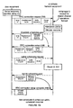
- FIGURES 1A and 1B show a conventional sequence of messages for transitioning from a radio resource connection (RRC) idle state to an RRC connected state in a conventional UMTS system.
- RRC radio resource connection
- a UE in an RRC idle state may initiate an RRC connection through a procedure as indicated in FIGURES 1A and 1B .
- the UE and network may exchange messages over logical control channels where each logical control channel is mapped to a common transport channel.
- Figure 1A shows the messaging exchanged over the air interface (Uu).
- the first message shown is the RRC connection request message, which includes the network-known UE identifier, shown as a global UE identifier (ID) and an establishment cause.
- ID global UE identifier
- the network-known UE identifier may be one of the network assigned temporary mobile subscriber identity (TMSI), the UE's international mobile subscriber identity (IMSI), or the UE's international mobile equipment identity (IMEI).
- TMSI temporary mobile subscriber identity
- IMSI international mobile subscriber identity
- IMEI UE's international mobile equipment identity
- the establishment cause indicates the reason for the UE requesting a connection with the network.
- a UE may request a connection when transmitting a response message to a paging message (paging response), when selecting a suitable cell while in idle mode (cell update), when selecting a suitable URA while in idle mode (URA update), and when receiving MBMS service or an MBMS point-to-point connection (MBMS connection).
- paging response when selecting a suitable cell while in idle mode (cell update), when selecting a suitable URA while in idle mode (URA update), and when receiving MBMS service or an MBMS point-to-point connection (MBMS connection).
- cell update
- the network performs admission control and allocates Radio Network Temporary Identifier (RNTI) values.
- RNTI Radio Network Temporary Identifier
- the network uses an admission control process to determine whether a requested service from the establishment cause can be supported by the network.
- Factors considered when performing admission control may include mobile access class for determining privileges, the Radio Resource Management status (RRM status) to determine availability of resources, details of the user's subscription, and equipment registers including lists of valid and stolen terminals.
- RRM status Radio Resource Management status
- the allocation of the RNTI values involves the network allocating a Serving Radio Network Controller (RNC) RNTI (S-RNTI), which is used by UE to identify itself to the serving RNC.
- the S-RNTI is also used by the SRNC to address the UE.
- An S-RNTI value is allocated by the Serving RNC to each UE having an RRC connection and is unique within the Serving RNC.
- the S-RNTI may be reallocated after the Serving RNC for the RRC connection has changed.
- the S-RNTI may be concatenated with an SRNC identifier (SRNC ID) received in a broadcast channel to form a unique RNTI (U-RNTI) within UTRAN.
- SRNC ID SRNC identifier
- U-RNTI unique RNTI
- the network may allocate a Cell Radio Network Temporary Identifier (C-RNTI).
- C-RNTI may be allocated and used on common transport channels.
- the C-RNTI value may be used to identify the UE on a cell basis.
- the decision to use the C-RNTI is made by the Controlling Radio Network Controller (CRNC).
- CRNC Controlling Radio Network Controller
- the network responds to the RRC connection request message with an RRC connection setup message including the global UE ID, the newly-allocated S-RNTI value, optionally a C-RNTI value, and a radio bearer configuration.
- the UE responds with an RRC connection setup complete message.
- the RRC connection setup complete message is accompanied by the C-RNTI value in a header field and includes the UE radio access capability. At this point, the UE enters an RRC connected state.
- the network may allocate an H-RNTI value to the UE within an RRC radio bearer setup message to the UE.
- the H-RNTI value is used to identify the UE on the high speed downlink shared channel.
- the RRC radio bearer setup message includes the allocated S-RNTI, the allocated H-RNTI and a shared channel radio bearer configuration.
- the UE completes the process by responding with an RRC radio bearer setup complete message. At this point, the UE and network have established a layer 2 context for shared channel operations.
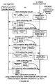
- FIGURE 1B shows elements of the UE and network equipment and the messaging between these elements.
- the UE includes a layer 3 comprising an RRC layer, a layer 2 comprising a Radio Link Control (RLC) layer and a medium access control (MAC) layer, and a layer 1 comprising a physical layer (L1).
- the Node B includes a layer 1 physical layer (L1).
- the RNC includes a layer 2 comprising a MAC layer and an RLC layer, and a layer 3 comprising an RRC layer and an RRM layer. Note additional layer 1 functions also exist in both the Node B and the RNC to provide physical connections between these entities (lub interface) although these are not shown for diagrammatical clarity.
- the RRC connection request message is initiated by the RRC layer in the UE.
- the RRC sends a message to the RLC layer which sends the RRC connection request message a common control channel (CCCH) mapped onto a random access channel (RACH) using an RLC transparent mode (TM).
- CCCH common control channel
- RACH random access channel
- TM RLC transparent mode
- the message sender does not include a message sequence identifier unlike acknowledged mode (AM) and unacknowledged mode (UM), which both include a message sequence identifier that may be used for identifying/reordering out of sequence packets and for identifying missing packets.
- the acknowledged mode (AM) additionally provides for message retransmission.
- the CCCH is a common logical control channel between the RLC and MAC layers and the RACH is a common transport channel between the MAC and L1 layers.
- the RRC connection request message is transmitted over the air interface (Uu) to the network.
- the Node B's layer 1 Upon receipt of the RRC connection request message, the Node B's layer 1 sends the message on a Random Access Channel (RACH) channel to the MAC layer of the RNC.
- RACH Random Access Channel
- the RACH channel is a common uplink transport channel used to carry control and data information from a UE over random access physical resources which may be shared by a plurality of UEs and are used for unscheduled data transmission.
- the MAC layer sends the message to the RLC layer over a CCCH channel.
- the RLC layer sends the message to the RRC layer, which sends the message to the RRM layer for admission control, allocation of the S-RNTI value, and optional allocation of the C-RNTI value.
- the RRM After successful admission control and allocation of the S-RNTI value, the RRM returns the allocated S-RNTI value to the RRC layer, which forms the RRC connection setup message to be sent in an unacknowledged mode (UM).
- UM unacknowledged mode
- a C-RNTI which identifies the UE within the cell, is also typically allocated. However, if a dedicated physical channel connection is to be immediately configured, the C-RNTI may be omitted.
- the RRC sends the RRC connection setup message to the RLC layer.
- the RLC layer sends the message over a CCCH channel to the MAC layer.
- CCCH is used because a common RNTI context does not yet exist between the network and the UE. That is, the network knows the RNTI values but the UE does not know the RNTI values at this stage.
- the MAC layer sends the message over a Forward Access Channel (FACH).
- FACH Forward Access Channel
- the FACH channel is a common downlink transport channel that may be used to carry control and data information to the UE when the network knows the location cell of the UE.
- the FACH may be shared by a plurality of UEs for unscheduled downlink data transmission.
- the Node B layer 1 transmits the message to the UE over the air interface (Uu).
- each UE monitoring the FACH channel decodes each and every RRC connection setup message and other messages in order to determine whether the enclosed message was addressed to it.
- the UE's layer 1 Upon receipt of the RRC connection setup message by the UE, the UE's layer 1 sends the message over a FACH channel to its MAC layer, which sends the message over a CCCH channel to the RLC layer, which in turn sends the message to the RRC layer of the UE.
- the UE RRC layer may then inspect the global ID field contained within the connection setup message to determine whether or not it matches the UE's own global ID. If not, the message is discarded. If the IDs match, the message is decoded and the UE registers the assignment of the S-RNTI and possibly the C-RNTI values. At this point, the UE now has a dedicated control channel (DCCH) allocated to it.
- DCCH dedicated control channel
- the UE responds using the RRC connection setup complete message, which is sent using an acknowledge mode (AM) to the network.
- the RRC layer sends a message to the RLC layer, which uses the DCCH channel to send the RRC connection setup complete message to the MAC layer.
- the MAC layer sends the message on a RACH (common transport) channel to the physical layer (L1), which transmits the message over the air interface (Uu) to the Node B.
- Data sent on DCCH on common transport channel resources is accompanied by a header field in which the C-RNTI is contained to distinguish the UE on a cell basis from the plurality of other UEs using the RACH (common transport) channel in that cell.
- the Node B receives the RRC connection setup complete message over the air interface (Uu). Its layer 1 sends the message to the RNC's MAC layer using a RACH channel. The MAC layer reads the header (containing the C-RNTI) and sends the message to the appropriate RLC entity using the appropriate DCCH channel. The RLC sends the message to the RRC layer.
- the network uses another value to identify a UE when the UE communicates over a high speed-downlink shared channel (HS-DSCH).
- This value is allocated by the RRC layer and is designated the HS-DSCH RNTI (H-RNTI) value.
- H-RNTI HS-DSCH RNTI
- the H-RNTI value is used as a temporary identifier while the UE is has an established connection over the HS-DSCH channel.
- the network sends the allocated H-RNTI value to the UE within a Radio Bearer Setup message using a DCCH channel between the RLC and MAC layers, and a FACH channel between the MAC layer and the UE's layer 1.
- the Node B transmits the message over the air interface (Uu) to the UE.
- the UE's layer 1 sends the message over a FACH channel to its MAC layer, which sends the message to the RLC on a DCCH channel.
- the RLC sends the message to the RRC layer, which responds with an RRC radio bearer setup complete message sent to the network using an RLC acknowledged mode (AM).
- AM RLC acknowledged mode
- the channel path between the UE's RRC layer and the RNC's RRC layer replicates the channel path described above for signaling the RRC connection complete message.
- the UE may subsequently utilize the high speed (hs) downlink shared (transport) channel for downlink communication. Resource allocations for this channel are granted by a scheduler located in a MAC-hs entity in Node-B.
- the MAC-hs entity can address the UE within the cell when making high speed downlink shared channel allocations by using the H-RNTI as a UE identifier.
- the MAC-hs entity is not shown in the figure as it does not take part in the connection setup procedure and associated messaging. Messaging used to establish the RRC connection is not conveyed on shared transport channels.
- the UE and the network have established and formed a layer 2 shared channel context and the network has allocated a shared channel identifier to the UE.
- the network allocated the identifier and exchanged three uplink messages and two downlink messages.
- a UE derives a temporary identifier (temp ID) to promptly establish a layer 2 context for more immediate communication over shared transport channels.
- This more immediate layer 2 context can obviate the need for extensive communication over common transport channels and can avoid a need to reserve significant portions of the total available radio resources for common channels.
- Such an assignment is typically slow to reconfigure and hence is not responsive to rapid changes in traffic loads.
- the UE derived temporary identifier is unique in the network during the duration of use, the UE may be uniquely identified on the shared channel and data may be communicated via dynamic assignment of shared channel resources rather than via statically-assigned common resources as is the case in conventional systems.
- the network may update the UE derived temporary identifier during or subsequent to the RRC connection process.
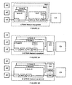
- FIGURES 2, 3A and 3B compare a UTRAN network to an evolved UTRAN (E-UTRAN) network operating with user equipment (UEs) and a core network (CN) in accordance with the present invention.
- E-UTRAN evolved UTRAN
- UEs user equipment
- CN core network
- FIGURE 2 shows multiple UEs and UTRAN network equipment.
- the UTRAN network equipment provides a link for the UE to the core network.
- the UTRAN network equipment also referred to as a Radio Access Network (RAN), includes one or more Radio Network Subsystem (RNS).
- RNS includes a Radio Network Controller (RNC) and one or more Node Bs.
- RNC Radio Network Controller
- the RNC provides RRM, RRC, RLC and MAC signaling layers and the Node B provides layer 1.
- FIGURE 3A shows an architecture to implement the invention in accordance with some embodiments of the present invention.
- An evolved UTRAN (E-UTRAN) network provides a long term evolution (LTE) platform to simply the UTRAN architecture and reduce the number of interfaces between components.
- LTE long term evolution
- the "evolved" and “E-” designation may be used to distinguish conventional components or elements that may be similar to the corresponding components or elements of the present invention.
- the E-UTRAN network provides a link for the UE to communicate with the core network (CN).
- the E-UTRAN includes an LTE gateway (LTE GW) coupled to one or more evolved Node Bs (E-Node Bs), which perform functions of both the Node B and the RNC of FIGURE 2 .
- LTE gateway LTE gateway
- E-Node Bs evolved Node Bs
- the LTE gateway provides an interface between the core network and the E-Node Bs.
- the E-Node B provides RRM, RRC, RLC, MAC and L1 signaling layers.
- FIGURE 3B shows an alternate architecture for an E-UTRAN network.
- the LTE gateway provides an interface between the core network and the E-Node Bs and also provides RRM and RRC layers for RRC signaling.
- the E-Node B provides RLC, MAC and L1 signaling layers.
- the embodiments of FIGURES 3A and 3B provide a MAC layer and an RLC layer collocated with the layer 1 processing, which aides in reducing signaling latencies.
- FIGURE 3A shows the collection of each of the layers used during the RRC connection establishment procedure, which further assists with reducing signal latencies.
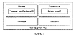
- FIGURE 4 shows components of user equipment in accordance with the present invention.
- User equipment comprises a memory for holding the UE-derived temporary identifier, a processor, program code executable to derive the UE-derived temporary identifier and store the identifier into the memory, and a transceiver to communicate with the E-UTRAN network equipment.
- the memory may be volatile memory such as RAM or non-volatile memory such as flash (EEPROM).
- the memory may be a component of the UE's circuitry or may be on a smart card installed in the UE's housing.
- the processor may be a reduced instruction set computer (RISC), a general processor, a specialized processor, a gate-logic implemented processor, or the like.
- RISC reduced instruction set computer
- the program code may be executable machine code, object code, scripts or other computer interpreted or compiled code.
- the program code may be compressed or uncompressed and may be encoded or not coded.
- the transceiver may be a code division multiple access (CDMA) transmitter/receiver pair operating in either a time division duplex (TDD) scheme or frequency division duplex (FDD) scheme.
- CDMA code division multiple access
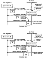
- FIGURES 5A and 5B show initial signaling sequences in accordance with the present invention.
- the UE first derives a temporary identifier (temp ID).
- the process of deriving a temporary identifier may vary among different implementations of the present invention.
- Derivation of a temporary identifier provides an immediate layer 2 context for layer 2 messaging over shared transport channels which are scheduled by the E-MAC entity in E-Node B.
- Derivation of a temporary identifier preferably occurs in a manner to minimize the probability to an acceptable level of two UEs deriving the same temporary identifier. If two UEs derive the same temporary identifier within a cell and attempt to use these during an overlapping period of time, additional collision detection and recovery procedures may be implemented.
- the UE-derived temporary identifier is a function of time or radio frame number.
- the function may vary in accordance with a pre-determined pattern or one signaled to the UE for example over a broadcast channel (BCH).
- BCH broadcast channel
- the variation pattern may contain a random element in its derivation.
- the use of a time-varying component or a time parameter (such as the system clock, super frame number, radio frame number, sub-frame number, time slot number) by the user equipment when deriving the temporary identifier may advantageously assist in reducing the probability of two or more users selecting the same temporary identifier within a given time-frame.
- the UE After deriving the temporary identifier, the UE transmits this UE-derived temporary identifier to the E-UTRAN network in a first uplink message.
- An initial L2 shared channel context is formed as soon as the network has received the initial temporary identifier; at this stage both the UE and the network know the value of the temporary identifier.
- this connection may be subject to collision, and a more permanent connection (without possibility for collision) may be formed once the network has reassigned a replacement temporary identifier.
- An allocated physical resource describes the resources allocated to the UE such as would allow for the UE to correctly encode and transmit or receive and decode the data message.
- the description may include attributes such as: (1) an explicit or relational time of transmission; (2) description of a physical channel resources, such as codes, frequencies, sub-carriers, time/freq codes, and/or the like; (3) a formatting type of the data on the resources; and/or (4) FEC encoding type, block size, modulation format and/or the like.
- This physical resource may be either an uplink resource (as shown in FIGURE 5A ) or a downlink resource (as shown in FIGURE 5B ).
- the network transmits a first downlink message to the UE including the UE-derived temporary identifier as a destination address and also including a description of the allocated physical resource.
- the UE and network communicate user traffic data or signaling data (data) over the allocated physical resource.
- FIGURE 5A shows data being communicated on an uplink scheduled, shared resource allocated by the network and described in the first downlink message.
- the UE can only transmit the data after the UE has received and processed the first downlink message containing the description of the allocated physical resource.
- the UE may initiate this sequence of deriving a temp ID and acquiring an uplink physical resource when the UE intends to send user traffic data or signaling data to the network.
- FIGURE 5B shows data being communicated on a downlink scheduled, shared resource allocated by the network and described in the first downlink message.
- the UE can only receive and process the data after the UE has received and processed the first downlink message containing the description of the allocated physical resource.
- the first downlink message is carried and received in a burst also containing the second downlink message. In this case, the UE processes the received burst to obtain the allocated physical resource. If the allocation indicates that the user traffic data or signaling data is contained in the same burst as the first downlink message containing the allocation, the UE may re-process the received burst to obtain the second downlink message.
- a conventional system configures both common and shared channels.
- the segmentation of resources limits the efficient use of the combined resources. For example, if most traffic at a particular time uses common channels, then the shared channels are left idle. Conversely, if most traffic is using the configured shared channels, then the common channels are left under utilized.
- a minimal set of resources may be assigned for unscheduled messages such as the first uplink message of FIGURES 5A and 5B .
- Uplink messages on this channel may be limited to short messages containing only the temp ID or alternatively containing the temp ID and an indication of what type of resource is being requested.
- Unscheduled downlink channels e.g., FACH
- FACH FACH
- the remainder of the resources may be dynamically allocated between control channel message (e.g., the first downlink message) and user traffic data or signaling data (i.e., second downlink or uplink message).
- control channel message e.g., the first downlink message
- user traffic data or signaling data i.e., second downlink or uplink message
- some embodiments of the present invention utilize a random access channel (RACH) for a first uplink message, a scheduled channel for downlink messages, and a common channel for subsequent uplink messages.
- RACH random access channel
- some embodiments of the present invention utilize a random access channel (RACH) for a first uplink message and scheduled channels for subsequent downlink and uplink messages.
- RACH random access channel
- some embodiments of the present invention utilize a random access channel (RACH) for an abbreviated initial uplink message and scheduled channels for subsequent downlink and uplink messages.
- FIGURES 6A and 6B show detailed signaling sequences using a scheduled downlink in accordance with the present invention.
- a UE derives a temporary identifier and sends the temporary identifier in a first uplink message to the network.
- the first uplink message contains an establishment cause parameter and two optional parameters: buffer occupancy and a global UE ID.
- the establishment cause and the global UE ID may be the same or similar to the corresponding parameters described above with reference to FIGURE 1A .
- the buffer occupancy may be used as an indication of the current pending data volume for transmission in the UE's transmission buffer and may be used by a scheduler at Node B to determine the extent of resources to grant for uplink transmission.
- the buffer occupancy could be a single bit, a range of quantized values, an absolute value in bytes, or a list of values, for example, one for each of a number of transmission flows, types or priority streams.
- the UE may transmit the RRC connection request message using transparent mode (TM).
- TM transparent mode
- the network Upon receipt of the RRC connection request message by the network equipment, the network performs admission control (described above with reference to FIGURE 1A ) and allocates a physical resource: either an uplink shared channel (UL-SCH) or a downlink shared channel (DL-SCH) as indicated by the establishment cause parameter.
- the network may also allocate an S-RNTI and a replacement temp ID.
- the network transmits a first downlink message containing a downlink scheduling grant indication including the temp ID to address the particular UE and a description of the allocated physical resource.
- the first downlink message may be transmitted on a shared physical control channel (SPCCH) monitored my UEs expecting or waiting for possible scheduling messages.
- SPCCH shared physical control channel
- a network may also send a replacement temporary identifier. The network may select the replacement temporary identifier from a list or table of unique identifiers not selectable by UEs. Such replacement temporary identifier insures that a message containing a UE-derived temporary identifier from a first UE will not collide with a message containing the same temporary identifier derived by a second UE.
- the UE-derived temporary identifier provides a limited duration hopefully-unique identifier that may be replaced by a more certain network selected unique identifier.
- the replacement temporary identifier may be sent in an RRC connection setup message, or may also be contained within the SPCCH grant message.
- UEs Upon receipt of the downlink scheduling grant message, UEs decode the short scheduling message and inspect the temp ID. Only the UE address by the temp ID needs to decode the longer message sent or to be sent on a downlink shared channel (DL-SCH). Other UEs not addressed by the scheduling grant message need not spend CPU cycles or battery resources to decode an RRC connection setup or other long messages to determine if the message is directed to it.
- DL-SCH downlink shared channel
- the UE identified by the temp ID receives and decodes the message transmitted in the allocated physical resource described in the downlink scheduling grant message.
- This second downlink message to the UE may contain a RRC connection setup message transmitted by the network using unacknowledged mode (UM).
- the RRC connection setup message may optionally contain a replacement temp ID, an allocated S-RNTI value, and/or a global UE ID. If the UE receives a replacement temp ID, it uses this replacement temp ID as its temporary identifier when signaling messages with the network.
- the global UE ID may be included in this first downlink message if received by the network from the RRC connection request message and if a conflict between overlapping temp IDs is detected by the network.
- the global UE ID is incorporated explicitly in the message.
- the global UE ID is used for encoding the downlink message (e.g., CRC).
- a radio bearer configuration may be transmitted to multiple UEs using a broadcast channel (BCH).
- BCH broadcast channel
- the UE responds to receiving and processing the RRC connection setup message by preparing and transmitting a RRC connection setup complete message using acknowledge mode (AM). If a replacement temp ID was provided by the network, the UE uses this new value as its temporary identifier.
- the RRC connection setup complete message may also contain UE radio access capability parameters indicating various capabilities of the UE.
- information contained within the conventional RRC radio bearer setup message may be broadcast on a BCH rather than signaled individually to each UE since the information describing a shared channel may be used by multiple UEs in a cell.
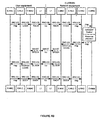
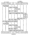
- FIGURE 6B shows elements of the UE and network equipment and the messaging between these elements.
- the UE includes a layer 3 comprising an evolved RRC (E-RRC) layer, a layer 2 comprising an evolved Radio Link Control (E-RLC) layer and an evolved MAC (E-MAC) layer, and a layer 1 comprising a physical layer (L1).
- the E-UTRAN network includes a layer 1 physical layer (L1), a layer 2 comprising an evolved MAC (E-MAC) layer and an evolved RLC (E-RLC) layer, and a layer 3 comprising an evolved RRC (E-RRC) layer and an evolved RRM (E-RRM) layer.
- the RRC connection request message is initiated by the E-RRC layer in the UE.
- the E-RRC sends a message to the E-RLC layer which sends the RRC connection request message a common control channel (CCCH) mapped onto a random access channel (RACH) using a transparent mode (TM).
- CCCH is a logical control channel between the E-RLC and E-MAC layers and the RACH is a common transport channel between the E-MAC and L1 layers.
- the RRC connection request message is transmitted over the air interface (Uu) to the network.
- the network equipment's layer 1 Upon receipt of the RRC connection request message, the network equipment's layer 1 sends the message on a Random Access Channel (RACH) channel to the MAC layer.
- the MAC layer sends the message to the E-RLC layer over a CCCH channel.
- the E-RLC layer sends the message to the E-RRC layer, which sends the message to the E-RRM layer for admission control and allocation of the replacement temporary identifier and optionally the replacement S-RNTI value.
- the E-RRM After admission control and optional replacement of the temporary ID and optional allocation of the S-RNTI value, the E-RRM returns the allocated values to the E-RRC layer, which forms the RRC connection setup message to be sent in an unacknowledged mode (UM).
- UM unacknowledged mode
- the E-RLC sends the RRC connection setup message to the E-RLC layer.
- the E-RLC layer sends the message over a DCCH or a CCCH channel to the E-
- the E-MAC layer sends a scheduling grant message over a shared physical control channel (SPCCH) to layer 1 for transmission to the UE.
- SPCCH shared physical control channel
- the UE's layer 1 receives the scheduling grant, which indicates the physical resource that will carry the RRC connection setup message.
- the E-MAC layer also transmits, either concurrently or subsequently, the RRC connection setup message to layer 1 on the allocated physical resource on the downlink shared channel (DL-SCH).
- Layer 1 transmits the RRC connection setup message over the air interface (Uu) to the UE.
- Uu air interface
- the UE's layer 1 Upon receipt of the RRC connection setup message by the UE, the UE's layer 1 sends the message over a DL-SCH channel to its E-MAC layer, which sends the message over a DCCH or CCCH channel to the E-RLC layer, which in turn sends the message to the E-RRC layer of the UE.
- the UE responds using the RRC connection setup complete message, which is sent using an acknowledge mode (AM) to the network.
- the E-RRC layer sends a message to the E-RLC layer, which uses the DCCH channel to send the RRC connection setup complete message to the E-MAC layer.
- the E-MAC layer sends the message on a RACH channel to the physical layer (L1), which transmits the message over the air interface (Uu) to the network.
- FIGURES 7A and 7B show detailed signaling sequences using a scheduled downlink and both non-scheduled and scheduled uplink in accordance with the present invention.
- the scheduling and exchange of the RRC connection request message and the RRC connection setup message, as well as admission control and allocation of resources are as described above with reference to FIGURES 6A and 6B .
- FIGURES 7A and 7B depart from the previous embodiment by sending subsequent uplink messages on shared resources.
- the UE's E-MAC layer when the UE's E-MAC layer receives the RRC connection setup complete message from its E-RLC layer, the UE's E-MAC layer first sends a scheduling request message on a RACH channel or an evolved RACH (E-RACH) channel.
- the short scheduling request message requests allocation of an uplink physical resource from the network.
- the scheduling request message is transmitted over the air interface (Uu) to the network.
- the scheduling request message is forwarded on the RACH channel to the network's E-MAC layer.
- the E-MAC layer allocates an uplink shared channel (UL-SCH) to the UE and describes the uplink allocation in a scheduling grant message sent on a shared physical control channel (SPCCH) from the E-MAC layer to layer 1, then over the air interface (Uu) to the UE's layer 1, which forwards the scheduling grant message on an SPCCH channel to the E-MAC layer.
- the E-MAC layer forwards the RRC connection setup complete message to layer 1 on the allocated UL-SCH resource for transmission to the network.
- shorter messages on the initial uplink resource may reduce the number collisions at the physical layer over the air interface.
- logical collisions (occurring due to a common temporary identifier independently derived by two UEs during an overlapping time period) may be overcome by collision recovery procedures at the UE and/or by collision recovery procedures in the network.
- resources that would otherwise be dedicated to RACH and/or FACH common channels may be either reduced or possibly eliminated; thus these resources are available for allocation to other channel traffic types.
- radio resources may be realized when compared to the case in which multiple traffic types are not allowed to share the same shared channel resources and instead need to be assigned separate resources.
- the scheduler can dynamically adapt the resources assigned to the varying instantaneous loads presented by each traffic type.
- variations in the traffic loads offered by each traffic type cannot be accommodated without reconfiguring the respective portions of the total radio resource space assigned firstly to common and secondly to shared channels.
- signaling latency and response time as viewed by the UE may be reduced.
- the use of scheduled channels means that a UE decodes short scheduling messages and no longer needs to monitor and decode each common channel message address to other UEs, which may lead to more efficient use of the UE's battery life.
- the connection setup signaling exchange over a high speed channel may occur faster than over a conventional common channel.
- FIGURES 8A and 8B show detailed signaling sequences using a scheduled downlink and a scheduled uplink in accordance with the present invention.
- the initial uplink communication is scheduled as well as subsequent communications.
- the UE Rather than transmitting an initial message containing the RRC connection request, the UE first sends a short scheduling request message to request the network allocate an uplink physical resource.
- the UE derives and includes a temporary identifier in the short uplink message.
- the message may optionally include a buffer occupancy parameter (described above) and a cause parameter.
- the cause parameter may indicate the reason for the request (e.g., uplink physical resource requested).
- the network allocates an uplink shared channel (UL-SCH) and transmits a scheduling grant on a shared physical control channel (SPCCH) including the UE-derived temporary identity and a description of the UL-SCH.
- the E-MAC layer of the UE receives the uplink scheduling grant message on the SPCCH channel and responds by sending the RRC connection request on the allocated UL-SCH physical channel.
- the RRC connection request message is received by the network which performs admission control and additional resource allocation as describe above with reference to FIGURES 7A and 7B .
- FIGURE 8A shows some embodiments may use acknowledged mode (AM) while other embodiments may use unacknowledged mode (UM) when communicating either or both of the RRC connection request and RRC connection setup messages.
- AM acknowledged mode
- UM unacknowledged mode
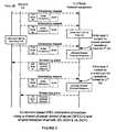
- FIGURES 9 and 10 illustrate processes of contention resolution in accordance with the present invention.
- This contention scenario occurs when two UEs derive and are using a common temporary identifier.
- Each UE transmits an RRC connection request message as described with reference to FIGURES 5A, 5B , 6A-B , 7A-B or 8A-B .
- Derivation of a temporary identifier preferably occurs in a manner to minimize the probability to an acceptable level of two UEs deriving the same temporary identifier.
- two UEs might derive the same temporary identifier within a cell. Therefore, additional collision detection and recovery procedures may be implemented.
- FIGURE 9 illustrates a remedy primarily instigated by the UEs.
- Two UEs each transmit an uplink message to the network using an identical temporary identifier (1 st temp ID).
- the uplink message may be a message transmitted on a RACH channel or an E-RACH.
- the message may be a scheduling request message (as shown) or some other message.
- the network may detect the duplicate identical temporary identifier in the two uplink messages.
- the network may elect to perform no following processing and will allow each UE to time out. After not receiving the expected downlink response, each UE discards the initially derived temporary identifier and derives another temporary identifier (2 nd temp ID and 3 rd temp ID, respectively).
- Each UE then retransmits the original uplink message using the newly derived temporary identifier.
- an initial layer 2 context is established between the respective UE and the network for shared channel operations.
- the network responds to each UE having a unique temp ID as described above.
- FIGURE 10 illustrates a remedy primarily instigated by the network.
- two UEs each transmit an uplink message to the network using an identical temporary identifier (temp ID).
- the uplink message may be a message transmitted on a RACH channel or an E-RACH.
- the message may be an RRC connection request message (as shown) or some other message.
- the network may detect an identical temporary identifier in the two uplink messages.
- two UEs have derived the same temp ID and may each may expect downlink signaling including this temp ID to be address to it. In such a case, the network may determine that a conflict or collision has occurred.
- one or both of the uplink messages includes a global UE ID, the UEs may be distinguished from one another. At this point, an initial layer 2 context is established between the respective UE and the network for shared channel operations.
- the network may transmit, on a control channel, a scheduling grant message allocated a downlink resource.
- the network may also transmit, on a traffic channel described in the scheduling grant message, a message incorporating a global UE ID.
- the network may transmit an RRC connection setup complete message incorporating addressed to the UEs using the conflicting UE-derived temporary identification.
- the network explicitly incorporates the global UE ID in the downlink message by including the global UE ID as a parameter.
- the network may incorporate the global UE ID by using the global UE ID to encode the downlink message.
- the incorporating may comprise computing a cyclic redundancy check (CRC) value using the network-known UE identifier.
- CRC cyclic redundancy check
- each UE may use its global UE ID to determine whether the global UE ID was incorporated explicitly as a parameter or alternatively to decode the message to determine whether the previously-transmitted global UE ID was used by the network to encode the message. Additionally, the network may respond by allocating a replacement temp ID to the UE that transmitted its global UE ID. Once one of the UEs receives a replacement temp ID, a unique layer 2 context is formed for both UEs for shared channel operation. The first UE will receive and properly decode the RRC connection setup message, which is encoded with its UE.
- the second UE will attempt to decode the RRC connection setup message but will fail because the message is encoded with an unknown global UE ID causing the second UE to discard the message and return to the downlink scheduling channel (SPCCH).
- the second UE will then receive a second downlink scheduling grant message sent by the network.
- the second UE will then properly receive and decode the RRC connection setup message addressed to it. Both UEs may complete the process by responding with an RRC connection setup complete message.
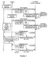
- FIGURES 11 and 12 illustrate processes of contention avoidance and resolution using multiple scheduling grant channels in accordance with the present invention.
- Some systems may configure multiple channels (e.g., multiple SPCCH channels) for communicating scheduling grant messages from the network to UEs. These channels may be pre-configured, may be defined by a standard, or may be sent to the UE (for example, sent via a broadcast channel or other system control signaling).
- a UE may derive or select a subset (i.e., a single channel or multiple channels) from the configured multiple channels for later monitoring of scheduling grant messages.
- the derived subset of channels that a UE will monitor may be referred to as a channel set.
- a UE may communicate the channel set either explicitly using a parameter or implicitly by use of a particular physical resource.
- a network may differentiate UEs that happened to have derived the same temporary identifier but have inevitably derived different channel sets.
- FIGURE 11 illustrates an example of a UE explicitly communicating a channel set to a network by transmitting an initial message containing an indication of the channel set.
- FIGURE 12 illustrates an example of a UE implicitly communicating a channel set by way of using a particular uplink physical resource to transmit an initial message to the network.
- a first UE prior to establishing a connection with the network equipment, derives a temporary identifier (temp ID) as discussed above.
- the first UE also derives a channel set. That is, the UE selects a scheduling grant channel (SPCCH) that it will monitor for future scheduling grant messages.
- SPCCH scheduling grant channel
- a UE may select more than one of the configured scheduling grant channels (SPCCHs), this being termed a channel set.
- a UE may select the channel set based on one or a combination of the following parameters: (1) the UE's global UE identifier such as its TMSI, IMSI or IMEI; (2) the derived temporary identifier; and (3) one or more characteristics of the physical resource the UE will use to transmit the initial message.
- the characteristics of the physical resource include a time parameter (such as a system clock, super frame number, radio frame number, sub-frame number, time slot number), a frequency parameter (such as a frequency band, channel number or sub-carrier number) and a code (such as a midamble code, a scrambling code, a channelization code, a time-frequency code or an orthogonal code).
- a time parameter such as a system clock, super frame number, radio frame number, sub-frame number, time slot number
- a frequency parameter such as a frequency band, channel number or sub-carrier number
- a code such as a midamble code, a scrambling code, a channelization code, a time-frequency code or an orthogonal code.
- the example shows a first UE deriving a temporary identifier (temp ID) in conjunction with a channel set.
- the channel set may be a single SPCCH channel number or a set of multiple SPCCH channel numbers.
- the channel set may be represented by a channel indication (e.g., channel indication #1).
- the channel set may be communicated by transmitting a channel indication value that represents an index to a table known to both the UE and the network.
- the table entries may represent a single channel number or may represent multiple channels from the set of possible channels.
- the first UE sends an initial message containing both the selected temporary identifier and a channel indication to communicate to the network which one or more channels the network should use to send scheduling grant messages.
- the initial message may be a scheduling request for scheduled uplink radio resources or an RRC connection request message sent as a first message during a connection setup process on non-scheduled uplink radio resources.
- the UE may also send a global UE identifier (such as a TMSI, IMSI or IMEI) for use in conflict detection and resolution as discussed above with reference to FIGURE 10 .
- the network may associate the temporary identifier and the channel set pair with a particular UE (e.g., the first UE).
- the example further shows a second UE initiating a connection simultaneously or a short time later.
- the second UE similarly derives a temporary identifier and a channel set represented by a channel indication (e.g., channel indication #2).
- a channel indication e.g., channel indication #2
- the example shows that the second UE derived the same temporary identifier (temp ID #1) as did the first UE. However, the second UE happens to have selected a different channel set.
- the second UE then sends the temporary identifier and the channel indication to the network in an initial message. Upon receipt of the initial message, the network may associate the received temporary identifier and channel set pair with the second UE.
- both UE's are associated with the same temporary ID, however, due to their selection of different and non-overlapping SPCCH channel sets as indicated in their channel indication parameters, unintended cross communication may be avoided.
- the first and second UE will monitor different SPCCH channels, therefore a common derived temporary identifier may be used by the network to address both UEs.
- the network will address both UEs with the same temporary identifier but will send a scheduling message to the first UE on one of the channels indicated by channel indication #1 and will send another scheduling message to the second UE on one of the channels indicated by channel indication #2. Hence, each UE will not process a scheduling grant message addressed to the other UE.
- a unique shared channel communication context has been formed by the system for each UE by virtue of the two UEs selecting different SPCCH channel sets. Communicating a channel indication may not completely remove the possibility for contention because two UEs may still derive the same temporary identifier and the same channel set. In this event, the contention resolution procedures discussed above with reference to FIGURES 9 and 10 may be applied within the context of the present invention.
- the network may communicate data with the first UE over a scheduled shared channel using the steps of: (1) receiving a temporary identifier (temp ID #1) and a channel indication (channel indication #1); (2) allocating downlink or uplink shared channel resources; (3) determining a scheduling grant channel (channel #1) from the received channel indication; (4) sending a scheduling grant message addressed to temp ID #1 over channel #1 and including a description of the allocated uplink or downlink shared channel resources; and (5) communicating data by transmitting or receiving the data on the allocated shared channel resources.
- the network may simultaneously or substantially simultaneously communicate with the second UE over a scheduled shared channel using the steps of: (1) receiving a temporary identifier (temp ID #1) and a channel indication (channel indication #2); (2) allocating downlink or uplink shared channel resources; (3) determining a scheduling grant channel (channel #2) from the received channel indication; (4) sending a scheduling grant message addressed to temp ID #1 over channel #2 and including a description of the allocated uplink or downlink shared channel resources; and (5) communicating data by transmitting or receiving the data on the allocated shared channel resources.
- the network may further re-assign a replacement temporary identifier to one or both UEs in order that each UE is assigned a unique temporary identifier, thus potentially obviating the need for grant channel restrictions when sending scheduling grant messages to each UE.
- the network may allow a UE to use a different set of SPCCH channels. For example, the network could re-assign a unique replacement temporary identifier to the UE and allowing the network to convey scheduling grants of uplink or downlink shared channel resources on any downlink SPCCH channel.
- UEs communicate the channel set implicitly.
- a first UE derives a temporary identifier and derives a physical resource (physical resource #1) before establishing a connection with the network equipment.
- the physical resource may be characterized by its time, frequency and code parameters.
- a UE may communication the channel set implicitly by the very use of the physical resource.
- the network may use one or more characteristics of the physical resource to infer the channel set to be used by the UE.
- the UE may determine a channel set then determine on which physical resource to send an initial message based on the determined channel set. In other embodiments, the UE may determine a physical resource to send an initial message then determine a channel set based on the determined physical resource.
- the network uses characteristics of the physical resource used by the UE to determine the channel set. For example, the time (e.g., time slot) of the initial message may indicate to the network that a particular downlink scheduling channel or set of channels will be monitored by the UE.
- the network may associate the temporary identifier with a particular one or more scheduling grant channels (SPCCHs) based on one or more characteristics of the physical resource (physical resource #1).
- SPCCHs scheduling grant channels
- the association of the temporary identifier or a physical resource with an SPCCH channel number or a channel set may vary as a function of the time. Alternatively, the association may be based upon a global UE ID received within an RRC connection request message. Each UE forms the same association between the transmitted temporary identifier and channel set as is formed by the network. This association may be accomplished similarly in both the UE and in the network. The network further associates the temporary identifier and channel set pair with a particular UE (in this case, the first UE).
- a second UE is shown to begin a connection establishment procedure.
- the second UE derives a temporary identifier and transmits an initial message to the network.
- the network Upon receipt of the initial message, the network similarly determines the channel set and associates the temporary identifier with one or more particular SPCCH channel numbers based on a characteristic of the physical resource (physical resource #2).
- an association between the temporary identifier and the implied channel set is based on a periodic function of time.
- a finite set of access period instances within the time period spanned between the sending of the two initial messages is configured such that the association between a temporary identifier and a channel set does not repeat.
- the transmission of temp ID #1 by the second UE at a later time causes its temp ID #1 to be associated with a different SPCCH channel number of that which is associated with the first UE.
- temp ID #1 is associated with SPCCH channel #1 for the first UE
- temp ID #1 is associated with SPCCH channel #2 for the second UE.
- the network may send scheduling grant messages to a UE using a scheduling grant channel known a priori to both the UE and the network and may communicate data uniquely with the first and second UEs over one or more scheduled shared channels as indicated by the scheduling grant messages.
- both UEs are associated with the same temporary identifier, however, due to their association with differing SPCCH channel numbers, unintended cross communication may be avoided as discussed above.
- a unique shared channel communication context has been formed by the system for each UE, attributed to the fact that the connection establishments were initiated using different physical resources and hence the UEs may be associated with different SPCCHs.
- this method completely removes the possibility of connection for non-simultaneous access attempts within a given time period. If a plurality of UEs derives a common temporary identifier but each transmits the initial message on different physical resources, then conflicts may be avoided if the UEs are reallocated replacement temporary identifiers.
- contentions may be experienced and conflicts may be resolved using contention resolution procedures such as described above with reference to FIGURES 9 and 10 .
- the length of the substantially contention-free access may be a function of the number of available SPCCH and the length and nature of the pattern describing the association between a temporary identifier and SPCCH channel number. It would therefore be advantageous for the network to assign unique replacement temporary identifiers to each UE accessing the system before the association pattern repeats in time. Thus, by designing the association pattern to have a length commensurate with the maximum expected time required to assign a replacement temporary identifier, the efficiency of the scheme may be optimized.
- some embodiments may include a transceiver using a code division multiple access (CDMA) transmitter/receiver pair operating in either a time division duplex (TDD) scheme or frequency division duplex (FDD) scheme.
- CDMA code division multiple access
- the transceiver may be a non-code division transceiver, such as used in a TDMA system, an FDMA system, an OFDM system or hybrids thereof (e.g. TMDA/FDMA, TDMA/CDMA, TDMA/OFDM, and TDMA/OFDM/CDMA).
- the transceiver may operate on bursts or may operate on a signal stream.
Landscapes
- Engineering & Computer Science (AREA)
- Computer Networks & Wireless Communication (AREA)
- Signal Processing (AREA)
- Databases & Information Systems (AREA)
- Mobile Radio Communication Systems (AREA)
- Communication Control (AREA)
Priority Applications (1)
| Application Number | Priority Date | Filing Date | Title |
|---|---|---|---|
| PL10171154T PL2247152T3 (pl) | 2006-01-04 | 2007-01-04 | Sposób przesyłania komunikatów RRC w systemie komunikacji bezprzewodowej |
Applications Claiming Priority (3)
| Application Number | Priority Date | Filing Date | Title |
|---|---|---|---|
| US11/325,829 US20070155390A1 (en) | 2006-01-04 | 2006-01-04 | Initial connection establishment in a wireless communication system |
| US11/330,820 US7912471B2 (en) | 2006-01-04 | 2006-01-11 | Initial connection establishment in a wireless communication system |
| EP07703660A EP1974575B1 (en) | 2006-01-04 | 2007-01-04 | Initial connection establishment in a wireless communication system |
Related Parent Applications (1)
| Application Number | Title | Priority Date | Filing Date |
|---|---|---|---|
| EP07703660.6 Division | 2007-01-04 |
Publications (2)
| Publication Number | Publication Date |
|---|---|
| EP2247152A1 EP2247152A1 (en) | 2010-11-03 |
| EP2247152B1 true EP2247152B1 (en) | 2011-11-23 |
Family
ID=38171311
Family Applications (4)
| Application Number | Title | Priority Date | Filing Date |
|---|---|---|---|
| EP10171154A Active EP2247152B1 (en) | 2006-01-04 | 2007-01-04 | Method to send RRC messages in a wireless communication system |
| EP07703660A Active EP1974575B1 (en) | 2006-01-04 | 2007-01-04 | Initial connection establishment in a wireless communication system |
| EP10175246A Withdrawn EP2293623A1 (en) | 2006-01-04 | 2007-01-04 | Method to send RRC messages in a wireless communication system |
| EP10171155A Active EP2259650B1 (en) | 2006-01-04 | 2007-01-04 | Method to send rrc messages in a wireless communication system |
Family Applications After (3)
| Application Number | Title | Priority Date | Filing Date |
|---|---|---|---|
| EP07703660A Active EP1974575B1 (en) | 2006-01-04 | 2007-01-04 | Initial connection establishment in a wireless communication system |
| EP10175246A Withdrawn EP2293623A1 (en) | 2006-01-04 | 2007-01-04 | Method to send RRC messages in a wireless communication system |
| EP10171155A Active EP2259650B1 (en) | 2006-01-04 | 2007-01-04 | Method to send rrc messages in a wireless communication system |
Country Status (9)
| Country | Link |
|---|---|
| US (10) | US7912471B2 (pl) |
| EP (4) | EP2247152B1 (pl) |
| JP (2) | JP4990911B2 (pl) |
| KR (2) | KR100992478B1 (pl) |
| AT (3) | ATE540553T1 (pl) |
| DE (1) | DE602007009039D1 (pl) |
| ES (2) | ES2384503T3 (pl) |
| PL (3) | PL1974575T3 (pl) |
| WO (1) | WO2007077250A2 (pl) |
Families Citing this family (124)
| Publication number | Priority date | Publication date | Assignee | Title |
|---|---|---|---|---|
| SE0300047D0 (sv) * | 2003-01-08 | 2003-01-08 | Ericsson Telefon Ab L M | MBMS in UTRAN |
| US20070155390A1 (en) * | 2006-01-04 | 2007-07-05 | Ipwireless, Inc. | Initial connection establishment in a wireless communication system |
| US7912471B2 (en) * | 2006-01-04 | 2011-03-22 | Wireless Technology Solutions Llc | Initial connection establishment in a wireless communication system |
| TWI533721B (zh) | 2006-01-31 | 2016-05-11 | 內數位科技公司 | 無線通信系統中提供及利用非競爭基礎頻道方法及裝置 |
| JP4786359B2 (ja) * | 2006-02-07 | 2011-10-05 | 株式会社エヌ・ティ・ティ・ドコモ | 移動局、無線アクセスネットワーク装置およびリソース要求方法 |
| JP2009527174A (ja) * | 2006-02-17 | 2009-07-23 | ノキア コーポレイション | Mimo受信機を提供する装置、方法およびコンピュータ・プログラム |
| WO2007100547A2 (en) * | 2006-02-24 | 2007-09-07 | Interdigital Technology Corporation | Wireless communication method and apparatus for selecting between transmission of short-version and full-version uplink scheduling requests |
| US8032088B2 (en) * | 2006-03-23 | 2011-10-04 | Nokia Corporation | Method, apparatus, network element and software product for location area update optimization |
| US8682357B2 (en) | 2006-05-02 | 2014-03-25 | Intellectual Ventures Holding 81 Llc | Paging in a wireless network |
| KR101151817B1 (ko) | 2006-05-03 | 2012-06-01 | 한국전자통신연구원 | 이동 통신 시스템에서의 상향 링크 제어 정보 전송 방법 |
| US8005041B2 (en) | 2006-05-08 | 2011-08-23 | Ipwireless, Inc. | Wireless communication system, apparatus for supporting data flow and method therefor |
| EP2030470B1 (en) * | 2006-06-20 | 2018-06-13 | LG Electronics Inc. | Procedure for initial access |
| US9265063B2 (en) | 2006-06-21 | 2016-02-16 | Electronics And Telecommunications Research Institute | Method to transmit downlink signaling message on cellular systems for packet transmission and method for receiving the message |
| KR101523480B1 (ko) | 2006-08-21 | 2015-05-28 | 인터디지탈 테크날러지 코포레이션 | Lte에서의 가변 데이터율 서비스를 위한 동적 자원 할당, 스케쥴링 및 시그널링 |
| KR101265643B1 (ko) * | 2006-08-22 | 2013-05-22 | 엘지전자 주식회사 | 무선 통신 시스템에서의 핸드오버 수행 및 그 제어 방법 |
| KR101424258B1 (ko) * | 2006-08-23 | 2014-08-13 | 엘지전자 주식회사 | 무선통신 시스템에서 랜덤 액세스 과정을 수행하는 방법 |
| EP3352482B1 (en) * | 2006-09-13 | 2021-06-02 | Telefonaktiebolaget LM Ericsson (publ) | Methods and apparatuses in a telecommunication system |
| WO2008038231A2 (en) * | 2006-09-27 | 2008-04-03 | Nokia Corporation | Method, system, and devices for informing a terminal about failure in resource reservation |
| US8619685B2 (en) * | 2006-10-02 | 2013-12-31 | Lg Electronics Inc. | Method for transmitting and receiving paging message in wireless communication system |
| ES2635276T3 (es) * | 2006-10-02 | 2017-10-03 | Telefonaktiebolaget Lm Ericsson (Publ) | Ejecución paralela condicional de señalización de estrato de acceso (AS) y de estrato sin acceso (NAS) |
| TW200826590A (en) * | 2006-10-19 | 2008-06-16 | Interdigital Tech Corp | HSPA protocol and architecture |
| WO2008054114A2 (en) * | 2006-10-30 | 2008-05-08 | Lg Electronics Inc. | Methods for re-direction of uplink access and for controlling random access in mobile communication system |
| WO2008054112A2 (en) * | 2006-10-30 | 2008-05-08 | Lg Electronics Inc. | Methods of performing random access in a wireless communication system |
| KR101443618B1 (ko) * | 2006-10-30 | 2014-09-23 | 엘지전자 주식회사 | 랜덤 접속 채널 메시지 응답 방법, 랜덤 접속 채널 메시지전송 방법 및 이를 지원하는 이동통신 단말 |
| KR100938754B1 (ko) | 2006-10-30 | 2010-01-26 | 엘지전자 주식회사 | 비연속 수신을 이용한 데이터 수신 및 전송 방법 |
| JP5074743B2 (ja) * | 2006-11-13 | 2012-11-14 | トヨタ自動車株式会社 | 中空糸膜モジュール、燃料電池システム |
| KR101342365B1 (ko) * | 2006-12-07 | 2013-12-16 | 엘지전자 주식회사 | 무선 통신 시스템에서의 데이터 전달 방법 |
| US9173223B2 (en) * | 2006-12-07 | 2015-10-27 | Lg Electronics Inc. | Method of transferring data in a wireless communication system |
| WO2008069617A2 (en) * | 2006-12-07 | 2008-06-12 | Lg Electronics Inc. | Method and transmitter for transmitting and method of receiving status report and structure of status data blocks in a mobile communication system |
| US8265000B2 (en) * | 2007-01-08 | 2012-09-11 | Lg Electronics Inc. | Method for receiving common channel in wireless communication and terminal thereof |
| US8155069B2 (en) * | 2007-01-09 | 2012-04-10 | Lg Electronics Inc. | Method of transmitting and receiving scheduling information in a wireless communication system |
| EP2119082A4 (en) * | 2007-01-09 | 2013-07-31 | Lg Electronics Inc | PREVIOUS CONTROL OF DATA RETRANSMISSION IN A WIRELESS COMMUNICATION SYSTEM |
| KR101384865B1 (ko) * | 2007-01-09 | 2014-04-16 | 엘지전자 주식회사 | 충돌 해결을 위한 랜덤 액세스 방법 |
| WO2008084985A2 (en) * | 2007-01-09 | 2008-07-17 | Lg Electronics Inc. | Method of transmitting and receiving data in a wireless communication system |
| BRPI0806551B1 (pt) * | 2007-01-10 | 2020-09-08 | Lg Electronics Inc. | Método para receber dados por um terminal em um sistema de comunicação sem fio, terminal para o mesmo e método para transmitir dados por uma rede a um terminal em um sistema de comunicação sem fio |
| CN101578783A (zh) * | 2007-01-10 | 2009-11-11 | Lg电子株式会社 | 用于在移动通信中构造数据格式的方法及其终端 |
| KR101211758B1 (ko) * | 2007-01-10 | 2012-12-12 | 엘지전자 주식회사 | 무선 통신 시스템의 블록 데이터 생성 방법 |
| KR101112145B1 (ko) * | 2007-02-09 | 2012-02-22 | 삼성전자주식회사 | 이동통신 시스템의 랜덤 액세스 프로시져에서 경쟁의 감지 방법 및 장치 |
| US8145271B2 (en) * | 2007-03-01 | 2012-03-27 | Ntt Docomo, Inc. | Base station apparatus and communication control method |
| KR20080084533A (ko) | 2007-03-16 | 2008-09-19 | 엘지전자 주식회사 | 이동통신 시스템에서의 데이터 통신 방법 |
| KR101397048B1 (ko) * | 2007-03-21 | 2014-05-20 | 엘지전자 주식회사 | 무선 통신 시스템에서의 데이터 전송 방법 |
| US8050187B2 (en) * | 2007-03-30 | 2011-11-01 | Tektronix, Inc. | System and method for real-time AAL2 channel detection in UTRAN |
| EP2156582A4 (en) * | 2007-04-09 | 2011-09-21 | Lg Electronics Inc | PROVISION AND USE OF INFORMATION ABOUT VIDEO WITH REGARD TO TRANSPORT SITUATIONS |
| WO2008133480A1 (en) | 2007-04-30 | 2008-11-06 | Lg Electronics Inc. | Method for transmitting or receiving data unit using header field existence indicator |
| KR101464748B1 (ko) | 2007-04-30 | 2014-11-24 | 엘지전자 주식회사 | 무선단말의 측정보고 기동방식 |
| WO2008133474A1 (en) * | 2007-04-30 | 2008-11-06 | Lg Electronics Inc. | Method of transmitting data in wireless communication system supporting multimedia broadcast/multicast service |
| WO2008133481A1 (en) | 2007-04-30 | 2008-11-06 | Lg Electronics Inc. | Method for performing an authentication of entities during establishment of wireless call connection |
| EP2137910B1 (en) | 2007-04-30 | 2015-07-08 | LG Electronics Inc. | Methods of transmitting data blocks in wireless communication system |
| KR101469281B1 (ko) * | 2007-04-30 | 2014-12-04 | 엘지전자 주식회사 | 무선단말의 상태 전환 방식 |
| KR20080097338A (ko) * | 2007-05-01 | 2008-11-05 | 엘지전자 주식회사 | 불연속 데이터 송수신 방법 |
| KR101468490B1 (ko) | 2007-05-02 | 2014-12-10 | 삼성전자주식회사 | 무선 통신 시스템에서 제어 채널들의 집합을 한정하여 송수신하는 방법 및 장치 |
| US20080273482A1 (en) * | 2007-05-02 | 2008-11-06 | Lg Electronics Inc. | Uplink access method for receiving a point-to-multipoint service |
| KR100917205B1 (ko) | 2007-05-02 | 2009-09-15 | 엘지전자 주식회사 | 무선 통신 시스템에서의 데이터 블록 구성 방법 |
| DE602007010259D1 (de) * | 2007-06-06 | 2010-12-16 | Siemens Ag | Verfahren zur Bereitstellung von Referenzdaten für eine Diagnose eines von einer Ereignisspur abhängigen Systems |
| ES2652668T3 (es) | 2007-06-18 | 2018-02-05 | Lg Electronics Inc. | Procedimiento y equipamiento de usuario para realizar una sincronización de enlace ascendente en un sistema de comunicación inalámbrica |
| CN101589566B (zh) | 2007-06-18 | 2013-06-12 | Lg电子株式会社 | 在无线通信系统中执行上行链路同步的方法 |
| GB2453315A (en) * | 2007-08-15 | 2009-04-08 | Nec Corp | Connection Identifier in a telecommunications network |
| CN101803445A (zh) * | 2007-09-17 | 2010-08-11 | Lm爱立信电话有限公司 | 在无线通信tdd系统中改进上行链路接入 |
| KR101387537B1 (ko) * | 2007-09-20 | 2014-04-21 | 엘지전자 주식회사 | 성공적으로 수신했으나 헤더 압축 복원에 실패한 패킷의 처리 방법 |
| EP2043391A1 (en) | 2007-09-25 | 2009-04-01 | Nokia Siemens Networks Oy | Omitting UE ID on an enhanced RACH process |
| US20090086698A1 (en) * | 2007-09-27 | 2009-04-02 | Interdigital Patent Holdings, Inc. | Method and apparatus for managing a collision in common e-dch transmissions |
| EP4090130A1 (en) | 2007-09-28 | 2022-11-16 | Pantech Wireless, LLC | Method and apparatus for terminating transmission of a message in an enhanced random access channel |
| US8867455B2 (en) * | 2007-10-01 | 2014-10-21 | Qualcomm Incorporated | Enhanced uplink for inactive state in a wireless communication system |
| WO2009055577A1 (en) * | 2007-10-25 | 2009-04-30 | Interdigital Patent Holdings, Inc. | Selecting transmission parameters for contention-based access in wireless systems |
| EP3820243A2 (en) * | 2007-10-25 | 2021-05-12 | Signal Trust for Wireless Innovation | Management and setup of enhanced mac-e/es resources |
| ATE524046T1 (de) * | 2007-10-29 | 2011-09-15 | Ericsson Telefon Ab L M | Verfahren und anordnung in einem telekommunikationssystem |
| US9215731B2 (en) * | 2007-12-19 | 2015-12-15 | Qualcomm Incorporated | Method and apparatus for transfer of a message on a common control channel for random access in a wireless communication network |
| AU2008341208B2 (en) | 2007-12-21 | 2013-07-18 | Telefonaktiebolaget L M Ericsson (Publ) | Methods and arrangements in a mobile telecommunications network |
| WO2009088877A2 (en) | 2008-01-02 | 2009-07-16 | Interdigital Patent Holdings, Inc. | Methods and apparatus for cell reselection |
| US8126054B2 (en) | 2008-01-09 | 2012-02-28 | Motorola Mobility, Inc. | Method and apparatus for highly scalable intraframe video coding |
| JP4886073B2 (ja) * | 2008-02-06 | 2012-02-29 | テレフオンアクチーボラゲット エル エム エリクソン(パブル) | ダウンリンク割り当てに関連する方法およびデバイス |
| CN101547421B (zh) * | 2008-03-25 | 2012-06-13 | 中兴通讯股份有限公司 | 随机接入响应消息的群标识生成方法及随机接入方法 |
| US7983215B2 (en) * | 2008-04-17 | 2011-07-19 | Infineon Technologies Ag | Communication device, method for transmitting an uplink transmission control message, method for receiving an uplink transmission control message |
| US8463277B2 (en) * | 2008-06-09 | 2013-06-11 | Mediatek Inc. | Method for allocating paging resource to a mobile station having multiple subscriber identities and resource allocating apparatus thereof |
| JP5393672B2 (ja) * | 2008-07-03 | 2014-01-22 | シャープ株式会社 | 無線通信システム、通信装置、無線通信方法、及び無線通信プログラム |
| KR20140105037A (ko) | 2008-08-08 | 2014-08-29 | 인터디지탈 패튼 홀딩스, 인크 | Mac 리셋 및 재구성 |
| US9357563B2 (en) | 2008-08-12 | 2016-05-31 | Google Technology Holdings LLC | Preventing misuse of random access procedure in wireless communication system |
| US9374837B2 (en) | 2008-08-12 | 2016-06-21 | Google Technology Holdings LLC | Preventing misuse of random access procedure in wireless communication system |
| US8290518B2 (en) * | 2009-02-05 | 2012-10-16 | Zte (Usa) Inc. | Paging mechanisms for mobile stations with multiple subscriptions |
| CN103716892B (zh) * | 2009-03-12 | 2017-06-09 | 交互数字专利控股公司 | 由wtru实施的用于多载波操作的方法以及该wtru |
| US8767846B2 (en) * | 2009-04-30 | 2014-07-01 | Qualcomm Incorporated | Joint layer 3 signalling coding for multicarrier operation |
| CN102804667A (zh) * | 2009-06-16 | 2012-11-28 | 交互数字专利控股公司 | 用于同步harq操作和干扰避免的方法和设备 |
| JP4975070B2 (ja) * | 2009-08-17 | 2012-07-11 | 株式会社エヌ・ティ・ティ・ドコモ | 移動通信方法、無線基地局及び移動局 |
| CN102158807B (zh) * | 2010-02-11 | 2015-01-28 | 中兴通讯股份有限公司 | Mcch通知信息的监听方法及装置、用户设备 |
| JP5508552B2 (ja) * | 2010-03-01 | 2014-06-04 | インターデイジタル パテント ホールディングス インコーポレイテッド | ハイブリッド式の局ごとおよびフローごとのアップリンク割り当てを実行するための方法および装置 |
| EP2367394B1 (en) * | 2010-03-12 | 2015-11-25 | BlackBerry Limited | Base station and method for receiving transmissions on an enhanced random access channel |
| JP5425679B2 (ja) * | 2010-03-24 | 2014-02-26 | シャープ株式会社 | 移動局装置、基地局装置、通信システム、通信方法、集積回路および移動局装置の制御プログラム |
| WO2011142574A2 (ko) * | 2010-05-11 | 2011-11-17 | 엘지전자 주식회사 | 하향링크 신호를 수신하는 방법 및 장치 |
| JP5147898B2 (ja) * | 2010-06-10 | 2013-02-20 | 株式会社エヌ・ティ・ティ・ドコモ | 無線制御装置及び通信制御方法 |
| EP2421321B1 (en) * | 2010-08-16 | 2017-12-27 | BlackBerry Limited | Methods and mobile station for reestablishing a connection by way of NAS procedures |
| KR20120071456A (ko) * | 2010-12-23 | 2012-07-03 | 한국전자통신연구원 | 사물 통신 단말을 위한 호 처리 방법 |
| GB2493780B (en) * | 2011-08-19 | 2016-04-20 | Sca Ipla Holdings Inc | Telecommunications apparatus and methods |
| US9271294B2 (en) * | 2011-11-14 | 2016-02-23 | Blackberry Limited | Method and system for requesting a service utilizing a sequence of codes |
| US9258820B2 (en) * | 2011-11-14 | 2016-02-09 | Blackberry Limited | Method and system for requesting a service utilizing a sequence of codes |
| US20130121258A1 (en) * | 2011-11-14 | 2013-05-16 | Research In Motion Limited | Method and system for requesting a service utilizing a sequence of codes |
| CN103326964B (zh) * | 2012-03-19 | 2016-08-03 | 华为技术有限公司 | 一种实现数据解调的方法、装置和系统 |
| RU2606199C2 (ru) | 2012-05-10 | 2017-01-10 | Нокиа Солюшнс энд Нетуоркс Ой | Обратная связь по эффективности услуги в сети радиодоступа |
| US9295093B2 (en) * | 2012-05-14 | 2016-03-22 | Broadcom Corporation | Using pointers to tagged frequencies to indicate candidates for use in redirection or reselection |
| JP5991051B2 (ja) * | 2012-07-06 | 2016-09-14 | 株式会社リコー | 無線通信システム、端末装置及びプログラム |
| WO2014031597A1 (en) | 2012-08-24 | 2014-02-27 | Oceus Networks Inc. | Mobile cellular networks |
| WO2014031689A1 (en) | 2012-08-24 | 2014-02-27 | Oceus Networks Inc. | Mobile cellular networks |
| EP3554141A1 (en) | 2012-10-30 | 2019-10-16 | Sony Corporation | System information update notification |
| WO2014179235A1 (en) | 2013-04-29 | 2014-11-06 | Oceus Networks Inc. | Mobile cellular network backhaul |
| US9107215B2 (en) * | 2013-07-18 | 2015-08-11 | Motorola Solutions, Inc. | Systems, devices, and methods for improving data capacity in a communications system by managing short addresses |
| JP6220235B2 (ja) * | 2013-11-11 | 2017-10-25 | 株式会社Nttドコモ | 基地局装置およびデコード方法 |
| US9615344B2 (en) * | 2013-12-19 | 2017-04-04 | Qualcomm Incorporated | Enhanced random access procedure for air-to-ground communications |
| WO2016003330A1 (en) * | 2014-06-30 | 2016-01-07 | Telefonaktiebolaget L M Ericsson (Publ) | Method and apparatuses for determining priority of a wireless terminal |
| US10285204B2 (en) | 2015-03-05 | 2019-05-07 | Telefonaktiebolaget Lm Ericsson (Publ) | Network node, a wireless device and methods therein for performing random access in a cell |
| US10735166B2 (en) * | 2015-05-29 | 2020-08-04 | Huawei Technologies Co., Ltd. | System and method of UE-centric radio access procedure |
| WO2016208614A1 (ja) * | 2015-06-24 | 2016-12-29 | 日本電信電話株式会社 | 無線ネットワークシステム |
| US10855597B2 (en) * | 2015-06-29 | 2020-12-01 | T-Mobile Usa, Inc. | Channel coding for real time wireless traffic |
| CN106961289B (zh) * | 2016-01-11 | 2020-11-13 | 中兴通讯股份有限公司 | 在无线设备中的多个无线电同时操作期间的干扰抑制 |
| US10873891B2 (en) | 2016-07-06 | 2020-12-22 | Oceus Networks, Llc | Secure network rollover |
| US9686238B1 (en) | 2016-07-07 | 2017-06-20 | Oceus Networks Inc. | Secure network enrollment |
| US9924427B2 (en) | 2016-07-07 | 2018-03-20 | Oceus Networks Inc. | Network backhaul access |
| US20180234839A1 (en) | 2017-02-13 | 2018-08-16 | Futurewei Technologies, Inc. | System and Method for User Equipment Identification and Communications |
| US10172078B2 (en) | 2017-03-31 | 2019-01-01 | Oceus Networks Inc. | Targeted user equipment-base station communication link |
| US20180302826A1 (en) * | 2017-04-18 | 2018-10-18 | Nokia Technologies Oy | Automatic Management Of Pre-Configuration Levels For Autonomous UE Mobility |
| CN118042491A (zh) * | 2018-04-04 | 2024-05-14 | 北京三星通信技术研究有限公司 | 用于配置中继节点的方法和设备 |
| SG11202007729WA (en) * | 2018-04-05 | 2020-09-29 | Ericsson Telefon Ab L M | Managing a temporary subscriber identifier having an extended length during connection setup in 5g networks |
| CN112313978B (zh) * | 2018-06-25 | 2022-04-08 | 株式会社Ntt都科摩 | 网络节点及基站装置 |
| US11246031B2 (en) * | 2018-08-15 | 2022-02-08 | Oceus Networks, Llc | Disguising UE communications in a cellular network |
| EP3648542A1 (en) * | 2018-10-31 | 2020-05-06 | ASUSTek Computer Inc. | Method and apparatus for transmission using preconfigured uplink resources in a wireless communication system |
| US11923874B2 (en) * | 2020-10-23 | 2024-03-05 | Qualcomm Incorporated | Codebook compression with lossy encoding for low probability events |
Family Cites Families (46)
| Publication number | Priority date | Publication date | Assignee | Title |
|---|---|---|---|---|
| US6411620B1 (en) * | 1991-01-31 | 2002-06-25 | Fujitsu Limited | Connectionless communication system |
| US5594776A (en) | 1994-09-14 | 1997-01-14 | Ericsson Inc. | Efficient paging system |
| JPH08263438A (ja) | 1994-11-23 | 1996-10-11 | Xerox Corp | ディジタルワークの配給及び使用制御システム並びにディジタルワークへのアクセス制御方法 |
| US5823173A (en) * | 1995-05-04 | 1998-10-20 | Slonaker; Robert M. | Paintball gun |
| WO1997020423A1 (en) * | 1995-11-29 | 1997-06-05 | Bell Communications Research, Inc. | A system and method for automatically screening and directing incoming calls |
| US6091717A (en) * | 1997-05-05 | 2000-07-18 | Nokia Mobile Phones Limited | Method for scheduling packet data transmission |
| US6862449B1 (en) | 1998-05-14 | 2005-03-01 | Fujitsu Limited | Reducing interference in cellular mobile communications networks |
| CA2341250C (en) * | 1998-07-21 | 2008-04-15 | Tachyon, Inc. | Method and apparatus for multiple access in a communication system |
| FI107424B (fi) * | 1999-03-22 | 2001-07-31 | Nokia Mobile Phones Ltd | Menetelmä ja järjestelmä multimediaan liittyvän informaation välittämiseen valmistautumiseksi pakettikytkentäisessä solukkoradioverkossa |
| KR100617916B1 (ko) | 1999-03-24 | 2006-08-30 | 퀄컴 인코포레이티드 | 예약방식 다중 액세스 |
| DE19931236C2 (de) * | 1999-07-07 | 2002-05-29 | Siemens Ag | Verfahren zur Zuweisung von Übertragungskapazität zu Verbindungen in einem Funk-Kommunikationssystem |
| US6829482B2 (en) | 2000-05-16 | 2004-12-07 | Telefonaktiebolaget Lm Ericsson (Publ) | Switching from dedicated to common channels when radio resources are controlled by drift radio network |
| US20060246910A1 (en) * | 2000-05-31 | 2006-11-02 | Jerry Petermann | Wireless devices for use with a wireless communications system with articial intelligence-based distributive call routing |
| KR100469735B1 (ko) * | 2000-07-18 | 2005-02-02 | 삼성전자주식회사 | 부호분할다중접속 이동통신시스템의 호 수용방법 |
| US7099372B2 (en) * | 2000-10-27 | 2006-08-29 | L-3 Communications Corporation | Spreading code hopping for synchronous DS-CDMA system to mitigate interference effects |
| US6850759B2 (en) * | 2001-02-22 | 2005-02-01 | Telefonaktiebolaget Lm Ericsson (Publ) | Reducing signaling in RNSAP protocol upon cell change in cellular telecommunications network |
| EP1257086A2 (de) * | 2001-05-07 | 2002-11-13 | Siemens Aktiengesellschaft | Vorrichtung und Verfahren zum Übersenden von Information |
| EP1274178A1 (en) * | 2001-06-28 | 2003-01-08 | Siemens Information and Communication Networks S.p.A. | Downlink power control in packet switching cellular systems with dynamic channel allocation |
| WO2003019958A1 (en) | 2001-08-24 | 2003-03-06 | Telefonaktiebolaget Lm Ericsson (Publ) | Method and means for redistribution of subscriber information in umts networks where the nodes are arranged in pools |
| JP2003234696A (ja) * | 2002-02-06 | 2003-08-22 | Mitsubishi Electric Corp | 送信電力補正方法、移動通信システムおよび移動局 |
| US7054630B2 (en) | 2002-05-13 | 2006-05-30 | Qualcomm Incorporated | Selective processing of the common control channel |
| KR100827136B1 (ko) * | 2002-05-17 | 2008-05-02 | 삼성전자주식회사 | 이동통신시스템에서의 시그널링 연결 설정방법 |
| DE60201733T2 (de) | 2002-05-17 | 2005-03-10 | Alcatel | Funkzugriffsnetz und Netzwerkelement |
| KR20030097559A (ko) * | 2002-06-22 | 2003-12-31 | 엘지전자 주식회사 | 무선이동통신 시스템의 멀티미디어 서비스 방법 |
| US7733896B2 (en) * | 2002-08-19 | 2010-06-08 | Alcatel-Lucent Usa Inc. | Dynamic access priority scheme |
| US7107014B2 (en) | 2002-10-24 | 2006-09-12 | Nokia Corporation | Transporting power control information |
| US20040139312A1 (en) | 2003-01-14 | 2004-07-15 | General Instrument Corporation | Categorization of host security levels based on functionality implemented inside secure hardware |
| CN1748386B (zh) | 2003-02-12 | 2013-05-22 | 三星电子株式会社 | 在多媒体广播/多播业务中管理用于寻呼用户设备的业务环境的方法 |
| US7062272B2 (en) * | 2003-02-18 | 2006-06-13 | Qualcomm Incorporated | Method and apparatus to track count of broadcast content recipients in a wireless telephone network |
| US7342896B2 (en) * | 2003-03-03 | 2008-03-11 | Sharp Laboratories Of America, Inc. | Centralized network organization and topology discover in Ad-Hoc network with central controller |
| EP1458208B1 (en) * | 2003-03-10 | 2005-05-04 | Alcatel | Method for routing messages between mobile control and cell control functional entities of a distributed radio access network |
| KR100548344B1 (ko) * | 2003-05-13 | 2006-02-02 | 엘지전자 주식회사 | 이동통신 시스템에서의 rrc연결방법 |
| KR100964679B1 (ko) | 2003-08-19 | 2010-06-22 | 엘지전자 주식회사 | 멀티미디어 방송 멀티 캐스트서비스에서 무선자원제어연결 모드 단말을 집계하는 방법 |
| US20050070320A1 (en) * | 2003-09-26 | 2005-03-31 | Dent Paul W. | Method and apparatus to reduce dispatch delays in dispatch communication networks |
| US7903637B2 (en) | 2004-01-22 | 2011-03-08 | Verizon Business Global Llc | Universal communications identifier |
| KR101071816B1 (ko) | 2004-04-02 | 2011-10-11 | 엘지전자 주식회사 | 무선 패킷 통신 시스템에서의 업링크 패킷 스케쥴링 방법 |
| WO2005120109A1 (en) * | 2004-06-04 | 2005-12-15 | Nortel Networks Limited | Method and system for soft handoff in mobile broadband systems |
| US7596380B2 (en) * | 2004-07-26 | 2009-09-29 | Lg Electronics Inc. | Changing serving radio network controller for mobile terminal supporting multimedia broadcast services |
| ATE369714T1 (de) | 2004-08-31 | 2007-08-15 | Matsushita Electric Industrial Co Ltd | EFFIZIENTE ßRISE OVER THERMAL (ROT)ß STEUERUNG WÄHREND EINES SANFTEN WEITERREICHENS |
| CA2484509C (en) | 2004-09-14 | 2009-04-21 | Jean-Louis Vill | Method and system for filtering electronic messages |
| US7158795B2 (en) | 2004-12-08 | 2007-01-02 | Spreadtrum Communications Corporation | Dummy PCH block detection for power saving in GSM handset |
| WO2006111785A1 (en) | 2005-04-21 | 2006-10-26 | Nokia Corporation | Supporting a transmission and a reception of data packets |
| US7773569B2 (en) * | 2005-05-19 | 2010-08-10 | Meshnetworks, Inc. | System and method for efficiently routing data packets and managing channel access and bandwidth in wireless multi-hopping networks |
| US20070058653A1 (en) * | 2005-09-13 | 2007-03-15 | Harris John M | Method and apparatus for efficient assigning of addresses for a mobile station |
| US7620367B2 (en) | 2005-10-31 | 2009-11-17 | Ipwireless, Inc. | Frequency domain unscheduled transmission in a TDD wireless communications system |
| US7912471B2 (en) | 2006-01-04 | 2011-03-22 | Wireless Technology Solutions Llc | Initial connection establishment in a wireless communication system |
-
2006
- 2006-01-11 US US11/330,820 patent/US7912471B2/en active Active
-
2007
- 2007-01-04 ES ES10171155T patent/ES2384503T3/es active Active
- 2007-01-04 EP EP10171154A patent/EP2247152B1/en active Active
- 2007-01-04 PL PL07703660T patent/PL1974575T3/pl unknown
- 2007-01-04 EP EP07703660A patent/EP1974575B1/en active Active
- 2007-01-04 AT AT10171155T patent/ATE540553T1/de active
- 2007-01-04 KR KR1020087019109A patent/KR100992478B1/ko active Active
- 2007-01-04 EP EP10175246A patent/EP2293623A1/en not_active Withdrawn
- 2007-01-04 KR KR1020107012731A patent/KR101140071B1/ko active Active
- 2007-01-04 AT AT10171154T patent/ATE535125T1/de active
- 2007-01-04 WO PCT/EP2007/050100 patent/WO2007077250A2/en not_active Ceased
- 2007-01-04 PL PL10171155T patent/PL2259650T3/pl unknown
- 2007-01-04 EP EP10171155A patent/EP2259650B1/en active Active
- 2007-01-04 PL PL10171154T patent/PL2247152T3/pl unknown
- 2007-01-04 DE DE602007009039T patent/DE602007009039D1/de active Active
- 2007-01-04 JP JP2008549013A patent/JP4990911B2/ja active Active
- 2007-01-04 AT AT07703660T patent/ATE480978T1/de not_active IP Right Cessation
- 2007-01-04 ES ES10171154T patent/ES2376719T3/es active Active
-
2011
- 2011-03-14 US US13/047,353 patent/US8412216B2/en active Active
- 2011-03-14 US US13/047,395 patent/US8412218B2/en not_active Expired - Fee Related
- 2011-03-14 US US13/047,366 patent/US8412217B2/en active Active
- 2011-03-14 US US13/047,250 patent/US8140086B2/en active Active
- 2011-03-14 US US13/047,303 patent/US8412213B2/en active Active
- 2011-03-14 US US13/047,318 patent/US8412214B2/en active Active
- 2011-03-14 US US13/047,335 patent/US8412215B2/en active Active
- 2011-03-14 US US13/047,382 patent/US8433331B2/en active Active
- 2011-03-14 US US13/047,269 patent/US8412212B2/en active Active
- 2011-07-19 JP JP2011158216A patent/JP2011244474A/ja active Pending
Also Published As
Similar Documents
| Publication | Publication Date | Title |
|---|---|---|
| EP2247152B1 (en) | Method to send RRC messages in a wireless communication system | |
| EP1974572B1 (en) | Initial connection establishment in a wireless communication system | |
| HK1149424B (en) | Method to send rrc messages in a wireless communication system | |
| HK1149419B (en) | Method to send rrc messages in a wireless communication system |
Legal Events
| Date | Code | Title | Description |
|---|---|---|---|
| PUAI | Public reference made under article 153(3) epc to a published international application that has entered the european phase |
Free format text: ORIGINAL CODE: 0009012 |
|
| AC | Divisional application: reference to earlier application |
Ref document number: 1974575 Country of ref document: EP Kind code of ref document: P |
|
| AK | Designated contracting states |
Kind code of ref document: A1 Designated state(s): AT BE BG CH CY CZ DE DK EE ES FI FR GB GR HU IE IS IT LI LT LU LV MC NL PL PT RO SE SI SK TR |
|
| 17P | Request for examination filed |
Effective date: 20110421 |
|
| GRAP | Despatch of communication of intention to grant a patent |
Free format text: ORIGINAL CODE: EPIDOSNIGR1 |
|
| RIC1 | Information provided on ipc code assigned before grant |
Ipc: H04W 76/02 20090101AFI20110511BHEP |
|
| RTI1 | Title (correction) |
Free format text: METHOD TO SEND RRC MESSAGES IN A WIRELESS COMMUNICATION SYSTEM |
|
| REG | Reference to a national code |
Ref country code: HK Ref legal event code: DE Ref document number: 1149424 Country of ref document: HK |
|
| GRAS | Grant fee paid |
Free format text: ORIGINAL CODE: EPIDOSNIGR3 |
|
| GRAA | (expected) grant |
Free format text: ORIGINAL CODE: 0009210 |
|
| AC | Divisional application: reference to earlier application |
Ref document number: 1974575 Country of ref document: EP Kind code of ref document: P |
|
| AK | Designated contracting states |
Kind code of ref document: B1 Designated state(s): AT BE BG CH CY CZ DE DK EE ES FI FR GB GR HU IE IS IT LI LT LU LV MC NL PL PT RO SE SI SK TR |
|
| REG | Reference to a national code |
Ref country code: GB Ref legal event code: FG4D |
|
| REG | Reference to a national code |
Ref country code: CH Ref legal event code: EP |
|
| REG | Reference to a national code |
Ref country code: IE Ref legal event code: FG4D |
|
| REG | Reference to a national code |
Ref country code: NL Ref legal event code: T3 |
|
| REG | Reference to a national code |
Ref country code: SE Ref legal event code: TRGR |
|
| REG | Reference to a national code |
Ref country code: DE Ref legal event code: R096 Ref document number: 602007018991 Country of ref document: DE Effective date: 20120202 |
|
| REG | Reference to a national code |
Ref country code: ES Ref legal event code: FG2A Ref document number: 2376719 Country of ref document: ES Kind code of ref document: T3 Effective date: 20120316 |
|
| LTIE | Lt: invalidation of european patent or patent extension |
Effective date: 20111123 |
|
| PG25 | Lapsed in a contracting state [announced via postgrant information from national office to epo] |
Ref country code: IS Free format text: LAPSE BECAUSE OF FAILURE TO SUBMIT A TRANSLATION OF THE DESCRIPTION OR TO PAY THE FEE WITHIN THE PRESCRIBED TIME-LIMIT Effective date: 20120323 Ref country code: LT Free format text: LAPSE BECAUSE OF FAILURE TO SUBMIT A TRANSLATION OF THE DESCRIPTION OR TO PAY THE FEE WITHIN THE PRESCRIBED TIME-LIMIT Effective date: 20111123 |
|
| PGFP | Annual fee paid to national office [announced via postgrant information from national office to epo] |
Ref country code: FR Payment date: 20120202 Year of fee payment: 6 |
|
| REG | Reference to a national code |
Ref country code: PL Ref legal event code: T3 |
|
| REG | Reference to a national code |
Ref country code: DE Ref legal event code: R082 Ref document number: 602007018991 Country of ref document: DE Representative=s name: MITSCHERLICH & PARTNER PATENT- UND RECHTSANWAE, DE |
|
| REG | Reference to a national code |
Ref country code: HK Ref legal event code: GR Ref document number: 1149424 Country of ref document: HK |
|
| REG | Reference to a national code |
Ref country code: NL Ref legal event code: SD Effective date: 20120507 |
|
| PG25 | Lapsed in a contracting state [announced via postgrant information from national office to epo] |
Ref country code: PT Free format text: LAPSE BECAUSE OF FAILURE TO SUBMIT A TRANSLATION OF THE DESCRIPTION OR TO PAY THE FEE WITHIN THE PRESCRIBED TIME-LIMIT Effective date: 20120323 Ref country code: LV Free format text: LAPSE BECAUSE OF FAILURE TO SUBMIT A TRANSLATION OF THE DESCRIPTION OR TO PAY THE FEE WITHIN THE PRESCRIBED TIME-LIMIT Effective date: 20111123 Ref country code: BE Free format text: LAPSE BECAUSE OF FAILURE TO SUBMIT A TRANSLATION OF THE DESCRIPTION OR TO PAY THE FEE WITHIN THE PRESCRIBED TIME-LIMIT Effective date: 20111123 Ref country code: SI Free format text: LAPSE BECAUSE OF FAILURE TO SUBMIT A TRANSLATION OF THE DESCRIPTION OR TO PAY THE FEE WITHIN THE PRESCRIBED TIME-LIMIT Effective date: 20111123 Ref country code: GR Free format text: LAPSE BECAUSE OF FAILURE TO SUBMIT A TRANSLATION OF THE DESCRIPTION OR TO PAY THE FEE WITHIN THE PRESCRIBED TIME-LIMIT Effective date: 20120224 |
|
| PGFP | Annual fee paid to national office [announced via postgrant information from national office to epo] |
Ref country code: TR Payment date: 20120123 Year of fee payment: 6 |
|
| RAP2 | Party data changed (patent owner data changed or rights of a patent transferred) |
Owner name: IP WIRELESS, INC. |
|
| REG | Reference to a national code |
Ref country code: DE Ref legal event code: R081 Ref document number: 602007018991 Country of ref document: DE Owner name: NVIDIA CORPORATION, US Free format text: FORMER OWNER: WIRELESS TECHNOLOGY SOLUTIONS LLC, NEW YORK, US Effective date: 20120509 Ref country code: DE Ref legal event code: R082 Ref document number: 602007018991 Country of ref document: DE Representative=s name: MITSCHERLICH & PARTNER PATENT- UND RECHTSANWAE, DE Effective date: 20120509 Ref country code: DE Ref legal event code: R081 Ref document number: 602007018991 Country of ref document: DE Owner name: NVIDIA CORPORATION, SANTA CLARA, US Free format text: FORMER OWNER: WIRELESS TECHNOLOGY SOLUTIONS LLC, NEW YORK, N.Y., US Effective date: 20120509 Ref country code: DE Ref legal event code: R082 Ref document number: 602007018991 Country of ref document: DE Representative=s name: MITSCHERLICH, PATENT- UND RECHTSANWAELTE PARTM, DE Effective date: 20120509 Ref country code: DE Ref legal event code: R082 Ref document number: 602007018991 Country of ref document: DE Representative=s name: MITSCHERLICH, PATENT- UND RECHTSANWAELTE, PART, DE Effective date: 20120509 |
|
| PG25 | Lapsed in a contracting state [announced via postgrant information from national office to epo] |
Ref country code: CY Free format text: LAPSE BECAUSE OF FAILURE TO SUBMIT A TRANSLATION OF THE DESCRIPTION OR TO PAY THE FEE WITHIN THE PRESCRIBED TIME-LIMIT Effective date: 20111123 |
|
| PGFP | Annual fee paid to national office [announced via postgrant information from national office to epo] |
Ref country code: FI Payment date: 20120111 Year of fee payment: 6 Ref country code: IT Payment date: 20120112 Year of fee payment: 6 Ref country code: SE Payment date: 20120112 Year of fee payment: 6 |
|
| REG | Reference to a national code |
Ref country code: FR Ref legal event code: TP Owner name: IPWIRELESS INC, US Effective date: 20120614 Ref country code: ES Ref legal event code: PC2A Owner name: IPWIRELESS, INC Effective date: 20120703 |
|
| PG25 | Lapsed in a contracting state [announced via postgrant information from national office to epo] |
Ref country code: CZ Free format text: LAPSE BECAUSE OF FAILURE TO SUBMIT A TRANSLATION OF THE DESCRIPTION OR TO PAY THE FEE WITHIN THE PRESCRIBED TIME-LIMIT Effective date: 20111123 Ref country code: SK Free format text: LAPSE BECAUSE OF FAILURE TO SUBMIT A TRANSLATION OF THE DESCRIPTION OR TO PAY THE FEE WITHIN THE PRESCRIBED TIME-LIMIT Effective date: 20111123 Ref country code: BG Free format text: LAPSE BECAUSE OF FAILURE TO SUBMIT A TRANSLATION OF THE DESCRIPTION OR TO PAY THE FEE WITHIN THE PRESCRIBED TIME-LIMIT Effective date: 20120223 Ref country code: DK Free format text: LAPSE BECAUSE OF FAILURE TO SUBMIT A TRANSLATION OF THE DESCRIPTION OR TO PAY THE FEE WITHIN THE PRESCRIBED TIME-LIMIT Effective date: 20111123 Ref country code: EE Free format text: LAPSE BECAUSE OF FAILURE TO SUBMIT A TRANSLATION OF THE DESCRIPTION OR TO PAY THE FEE WITHIN THE PRESCRIBED TIME-LIMIT Effective date: 20111123 |
|
| PGFP | Annual fee paid to national office [announced via postgrant information from national office to epo] |
Ref country code: NL Payment date: 20120117 Year of fee payment: 6 |
|
| PG25 | Lapsed in a contracting state [announced via postgrant information from national office to epo] |
Ref country code: RO Free format text: LAPSE BECAUSE OF FAILURE TO SUBMIT A TRANSLATION OF THE DESCRIPTION OR TO PAY THE FEE WITHIN THE PRESCRIBED TIME-LIMIT Effective date: 20111123 Ref country code: MC Free format text: LAPSE BECAUSE OF NON-PAYMENT OF DUE FEES Effective date: 20120131 |
|
| REG | Reference to a national code |
Ref country code: CH Ref legal event code: PL |
|
| REG | Reference to a national code |
Ref country code: AT Ref legal event code: MK05 Ref document number: 535125 Country of ref document: AT Kind code of ref document: T Effective date: 20111123 |
|
| PLBE | No opposition filed within time limit |
Free format text: ORIGINAL CODE: 0009261 |
|
| STAA | Information on the status of an ep patent application or granted ep patent |
Free format text: STATUS: NO OPPOSITION FILED WITHIN TIME LIMIT |
|
| REG | Reference to a national code |
Ref country code: DE Ref legal event code: R082 Ref document number: 602007018991 Country of ref document: DE Representative=s name: MITSCHERLICH & PARTNER PATENT- UND RECHTSANWAE, DE |
|
| REG | Reference to a national code |
Ref country code: IE Ref legal event code: MM4A |
|
| 26N | No opposition filed |
Effective date: 20120824 |
|
| PG25 | Lapsed in a contracting state [announced via postgrant information from national office to epo] |
Ref country code: LI Free format text: LAPSE BECAUSE OF NON-PAYMENT OF DUE FEES Effective date: 20120131 Ref country code: CH Free format text: LAPSE BECAUSE OF NON-PAYMENT OF DUE FEES Effective date: 20120131 |
|
| REG | Reference to a national code |
Ref country code: DE Ref legal event code: R082 Ref document number: 602007018991 Country of ref document: DE Representative=s name: MITSCHERLICH & PARTNER PATENT- UND RECHTSANWAE, DE Effective date: 20121022 Ref country code: DE Ref legal event code: R081 Ref document number: 602007018991 Country of ref document: DE Owner name: NVIDIA CORPORATION, US Free format text: FORMER OWNER: IPWIRELESS, INC., SAN FRANCISCO, US Effective date: 20121022 Ref country code: DE Ref legal event code: R081 Ref document number: 602007018991 Country of ref document: DE Owner name: NVIDIA CORPORATION, SANTA CLARA, US Free format text: FORMER OWNER: IPWIRELESS, INC., SAN FRANCISCO, CALIF., US Effective date: 20121022 Ref country code: DE Ref legal event code: R082 Ref document number: 602007018991 Country of ref document: DE Representative=s name: MITSCHERLICH, PATENT- UND RECHTSANWAELTE PARTM, DE Effective date: 20121022 Ref country code: DE Ref legal event code: R082 Ref document number: 602007018991 Country of ref document: DE Representative=s name: MITSCHERLICH, PATENT- UND RECHTSANWAELTE, PART, DE Effective date: 20121022 |
|
| REG | Reference to a national code |
Ref country code: DE Ref legal event code: R097 Ref document number: 602007018991 Country of ref document: DE Effective date: 20120824 |
|
| PG25 | Lapsed in a contracting state [announced via postgrant information from national office to epo] |
Ref country code: AT Free format text: LAPSE BECAUSE OF FAILURE TO SUBMIT A TRANSLATION OF THE DESCRIPTION OR TO PAY THE FEE WITHIN THE PRESCRIBED TIME-LIMIT Effective date: 20111123 Ref country code: IE Free format text: LAPSE BECAUSE OF NON-PAYMENT OF DUE FEES Effective date: 20120104 |
|
| REG | Reference to a national code |
Ref country code: GB Ref legal event code: 732E Free format text: REGISTERED BETWEEN 20130131 AND 20130206 |
|
| REG | Reference to a national code |
Ref country code: FR Ref legal event code: TP Owner name: NVIDIA CORPORATION, US Effective date: 20130408 |
|
| PGFP | Annual fee paid to national office [announced via postgrant information from national office to epo] |
Ref country code: ES Payment date: 20120213 Year of fee payment: 6 |
|
| REG | Reference to a national code |
Ref country code: NL Ref legal event code: V1 Effective date: 20130801 |
|
| REG | Reference to a national code |
Ref country code: NL Ref legal event code: SD Effective date: 20130820 Ref country code: NL Ref legal event code: TD Effective date: 20130820 Ref country code: NL Ref legal event code: V1 Effective date: 20130801 |
|
| REG | Reference to a national code |
Ref country code: SE Ref legal event code: EUG |
|
| REG | Reference to a national code |
Ref country code: FR Ref legal event code: ST Effective date: 20130930 |
|
| PG25 | Lapsed in a contracting state [announced via postgrant information from national office to epo] |
Ref country code: NL Free format text: LAPSE BECAUSE OF NON-PAYMENT OF DUE FEES Effective date: 20130801 Ref country code: FI Free format text: LAPSE BECAUSE OF NON-PAYMENT OF DUE FEES Effective date: 20130104 Ref country code: SE Free format text: LAPSE BECAUSE OF NON-PAYMENT OF DUE FEES Effective date: 20130105 |
|
| PG25 | Lapsed in a contracting state [announced via postgrant information from national office to epo] |
Ref country code: FR Free format text: LAPSE BECAUSE OF NON-PAYMENT OF DUE FEES Effective date: 20130131 |
|
| PG25 | Lapsed in a contracting state [announced via postgrant information from national office to epo] |
Ref country code: IT Free format text: LAPSE BECAUSE OF NON-PAYMENT OF DUE FEES Effective date: 20130104 |
|
| REG | Reference to a national code |
Ref country code: PL Ref legal event code: LAPE |
|
| PG25 | Lapsed in a contracting state [announced via postgrant information from national office to epo] |
Ref country code: PL Free format text: LAPSE BECAUSE OF NON-PAYMENT OF DUE FEES Effective date: 20130104 Ref country code: LU Free format text: LAPSE BECAUSE OF NON-PAYMENT OF DUE FEES Effective date: 20120104 |
|
| REG | Reference to a national code |
Ref country code: ES Ref legal event code: FD2A Effective date: 20140613 |
|
| PG25 | Lapsed in a contracting state [announced via postgrant information from national office to epo] |
Ref country code: HU Free format text: LAPSE BECAUSE OF FAILURE TO SUBMIT A TRANSLATION OF THE DESCRIPTION OR TO PAY THE FEE WITHIN THE PRESCRIBED TIME-LIMIT Effective date: 20070104 |
|
| PG25 | Lapsed in a contracting state [announced via postgrant information from national office to epo] |
Ref country code: ES Free format text: LAPSE BECAUSE OF NON-PAYMENT OF DUE FEES Effective date: 20130105 |
|
| PG25 | Lapsed in a contracting state [announced via postgrant information from national office to epo] |
Ref country code: TR Free format text: LAPSE BECAUSE OF NON-PAYMENT OF DUE FEES Effective date: 20130104 |
|
| REG | Reference to a national code |
Ref country code: DE Ref legal event code: R079 Ref document number: 602007018991 Country of ref document: DE Free format text: PREVIOUS MAIN CLASS: H04W0076020000 Ipc: H04W0076100000 |
|
| PGFP | Annual fee paid to national office [announced via postgrant information from national office to epo] |
Ref country code: GB Payment date: 20241219 Year of fee payment: 19 |
|
| PGFP | Annual fee paid to national office [announced via postgrant information from national office to epo] |
Ref country code: DE Payment date: 20241218 Year of fee payment: 19 |