EP2246948A2 - Assembly for compensating for magnetic fields in high power cables - Google Patents
Assembly for compensating for magnetic fields in high power cables Download PDFInfo
- Publication number
- EP2246948A2 EP2246948A2 EP10004541A EP10004541A EP2246948A2 EP 2246948 A2 EP2246948 A2 EP 2246948A2 EP 10004541 A EP10004541 A EP 10004541A EP 10004541 A EP10004541 A EP 10004541A EP 2246948 A2 EP2246948 A2 EP 2246948A2
- Authority
- EP
- European Patent Office
- Prior art keywords
- conductor
- arrangement
- magnetic field
- hollow cylinder
- field shielding
- Prior art date
- Legal status (The legal status is an assumption and is not a legal conclusion. Google has not performed a legal analysis and makes no representation as to the accuracy of the status listed.)
- Granted
Links
Images

Classifications
-
- H—ELECTRICITY
- H02—GENERATION; CONVERSION OR DISTRIBUTION OF ELECTRIC POWER
- H02G—INSTALLATION OF ELECTRIC CABLES OR LINES, OR OF COMBINED OPTICAL AND ELECTRIC CABLES OR LINES
- H02G3/00—Installations of electric cables or lines or protective tubing therefor in or on buildings, equivalent structures or vehicles
- H02G3/02—Details
- H02G3/04—Protective tubing or conduits, e.g. cable ladders or cable troughs
- H02G3/0462—Tubings, i.e. having a closed section
- H02G3/0481—Tubings, i.e. having a closed section with a circular cross-section
Definitions
- the invention relates to an arrangement for magnetic field compensation in power cables for alternating current.
- Magnetic shielding of buried three-phase cables can be achieved by drawing the three wires of the cable system into a tube of high permeability material, such as a commercial steel tube.
- a steel tube for shielding is the fact that on the one hand for mechanical reasons and for the purpose of shielding a large wall thickness of a few millimeters (about 4 ... 10 mm) must have and on the other hand it is not flexible and welded together in short pipe sections must become. In addition, it must be protected against corrosion by the soil moisture by providing it on the outside with a plastic jacket and on the inside mostly with a concrete filling.
- Another technical difficulty is that for installation reasons initially three additional plastic pipes are to be fed into the steel pipe, in which then the three cable cores can be retracted individually.
- Shielding jackets have already become known in cable technology, which consist of at least one layer of soft magnetic material strips wound onto a cable ( DE 19807527 A1 . DE 3123040 A1 . DE 1440008 A1 . EP 0290343 B1 ). Such constructions are intended for the direct manufacture of a cable. The arrangements are not suitable for subsequent attachment to or via a cable during cable installation, especially when the cable is in a cable trench.
- Compensating conductors can be used to reduce the magnetic fields in the vicinity of high-voltage cables. These are placed over a certain length parallel to the cables and short-circuited at their ends (so-called "passive loops"), so that the cable currents induce compensating currents into these conductors.
- Passive loops For example, such an arrangement is in the EP 1598911 A1 for a power cable (with at least two phase conductors).
- at least one first compensation conductor is installed along a first phase conductor
- at least one second compensation conductor is installed independently of the first compensation conductor along a second phase conductor.
- the at least one first compensation conductor and the at least one second compensation conductor are then bridged at least at a start portion and at an end portion to form a closed circuit between the two compensation conductors.
- EP 1598911 A1 Plate-shaped compensation conductors are proposed.
- Such a compensation measure is particularly important for the sleeve areas, since there the cables for assembly reasons with a particularly large distance - usually in one plane - and thus cause particularly large magnetic fields.
- the effort to comply with magnetic field restrictions can be significant, as determined in our own investigations.
- the invention is used on a limited length section along an AC power cable, wherein each phase conductor shielding the formed as a hollow cylinder shielding arrangement are present, and the hollow cylinder has the length of the length section.
- the shielding means further comprises at least one forward conductor and at least one return conductor disposed along each of the phase conductors of the power cable.
- Each of the phase conductors is wrapped in sections along the length of the hollow cylinder with a harness made of highly permeable material.
- the hollow cylinder with harness is to be referred to below as induction tube. Structure and material of a high-permeability harnesses are for example from DE 102006013553 A1 known.
- the harness is inserted in a wall of the hollow cylinder, wherein in the wood cylinder at least one Hinleiter runs.
- At least one (further) return conductor is present.
- the at least one return conductor may be parallel to each phase conductor above or also below the harness. Outside the hollow cylinder - also parallel to each phase conductor - with a length greater than the length of the hollow cylinder is at least parallel to each phase conductor at least one compensation conductor, and at least one Hinleiter is connected via at least one compensation conductor with at least one return conductor in series, so that a closed Short circuit conductor loop is formed. It is also possible to interconnect several short-circuit conductor loops parallel to each other by using several return and return conductors and compensation conductors.
- the conductor connections between the conductors which can be made via end-to-end connection contacts to the return conductor or else as fixed connections, for example by welding, are made outside the length section of the induction tube.
- the conductor loop can in the simplest case consist of one turn. If several return conductors are included in the conductor loop, conductor loops are formed with several turns, whereby the harness is looped around at least once.
- the high-permeable harness construction enhances the current induced in the conductor loop (s) and acting as compensation.
- the arrangement can lie directly in earth. It is not limited to sleeve areas: even with compensation conductors along the entire cable route, such induction tubes can be installed at certain intervals in order to increase the compensation currents. Finally, it is also possible to design the induction tube over long distances in sensitive areas of a route as a laying pipe for single conductor cable. This measure is particularly interesting when laying in steel pipes.
- a support tube made of plastic which can also be flexible (for example, as a corrugated tube) can be designed for ease of laying, the one Hinleiter, at least partially formed as a metal reinforcement.
- the metal reinforcement can also be designed as a tube. At both ends of the metal reinforcement, or the metal tube in turn contact points for connection to the compensation conductor, or with the return conductor are present, also to form a conductor loop.
- At least one compensation conductor can be pushed on, a mechanically adjustable in its impedance high-permeability magnetic core.
- the induction tube should be wrapped with an external corrosion protection, in particular, the highly permeable harness is protected against corrosion.
- a heat sink can be placed around the induction tube.
- the heat sink may consist of a metal tube, or it may consist of highly heat-conductive cement. To the latter alternative can DE 102007026648 B3 to get expelled.
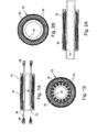
- a compensation or shielding arrangement in which a hollow cylinder 12, 12 ', 12 “(the” induction tube ”) is used, so that in each case an arrangement for a special laying situation with limited length is available no massive iron cores and is also suitable for the direct burial of sleeves Fig. 1A and 1B an induction tube (length L1 about 0.5 m to 2 m) shown, which is pushed before the sleeve assembly each on a - not shown - cable core (phase conductor 10).
- This induction tube consists of an inner support tube 14. On the support tube 14 are - parallel or stranded - applied one or more (insulated) conductor 16, which are provided at their ends with terminal contacts 18.
- the conductors are each forward and return conductors in a short-circuit conductor loop formed with a compensation conductor.
- the hollow cylinder will now be with multiple layers of the same "City cables" used high-permeable electrical steel 20 wrapped.
- a suitable enclosure with shrink tubing or the like provides for the corrosion protection 30 of this arrangement. It should be ensured that the phase conductor 10 is coaxial in the longitudinal axis of the induction tube, which by spacers 32 (see. Fig. 4 ) is difficult to realize.
- Fig. 1B There are sixteen conductors (to which terminal contacts 18 may be attached), of which eight can be connected as forward conductors (16) and eight as return conductors (16).
- a short-circuit conductor loop 25 for magnetic field compensation is generated in that - starting from a first forward conductor - a compensation conductor 24 parallel to the phase conductor at least over a critical or sensitive area (L2) in which the magnetic field compensation is to be made with the (at least first ) Is placed in series in the induction tube and the compensation conductor 24 in a short-circuit conductor loop (with at least one turn) is returned back to a return conductor (see. Fig. 5 ).
- the extension of the short-circuit conductor loop 24, 25 outside the tubular arrangement extends in a length L2 (see. Fig. 5 ) in which the magnetic shield is to be made (for example, according to the length of a sleeve).
- a length L2 in which the magnetic shield is to be made (for example, according to the length of a sleeve).
- Eight conductor loops each having eight compensation conductors can be formed, or several forward and return conductors can be used as windings, so that fewer conductor loops can be produced with a plurality of windings.
- FIGS. 2A and 2B A variant shows FIGS. 2A and 2B , Here is in place of the support tube 14 in Fig. 1 a conductive tube 16 ", for example made of aluminum, is provided at the same time as the metal carrier tube forms a single (forward) conductor 16" in the induction tube. The rest of the construction corresponds to the Fig. 1 , with return conductors outside the harness, see illustration in Fig. 5B ,
- an embodiment can be considered, in which the arrangements according to Fig. 1 (and Fig. 5 ) slit, so in the form of two half-cylinders can be constructed.
- the induction tube would not have to be pushed onto the cable core, but could also be put on from the outside after socket installation.
- overlap areas of the magnetic harness should be realized.
- the Fig. 3 shows - as in Fig. 1 - An arrangement in which, however, the support tube 14 is filled with highly thermally conductive special concrete 26. On the outside, the arrangement is surrounded by a block of the same material 26. The resulting in the magnetic harness 20 losses are low, experience has shown.
- the outside space of the arrangement can, as in Fig. 3 be filled with this material, so that the additional losses can be easily dissipated to the outside.
- the induction tube In order to improve the heat dissipation on, and possibly also as corrosion protection of the induction tube is proposed and in the Fig. 4 shown, the induction tube to the outside with a thick-walled metal tube 28, for example, of aluminum or copper, to envelop, in order to force over this pipe heat dissipation in the longitudinal direction. In the end region of this metal tube 28 additional cooling flags o.ä. ensure a further improved heat dissipation.
- the interior of this metal tube and the spaces in the support tube can be filled again with the highly thermally conductive special concrete 26.
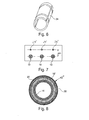
- Fig. 5A For example, the laying of compensation conductor loops 24, 25 on a phase conductor (not shown) inside the induction tube is shown schematically. Beyond the length L1 of the induction tube, up to a length L2, two compensation conductors 24 are guided, which are connected in series with the forward and return conductors 16 under the harness 20 in one turn.
- the Fig. 5B shows a circuit of a total of four (out) conductors 16 below the harness and a return conductor above the harness 20, which are connected to the compensation conductors 24 to two current loops 25 each having two turns. If the arrangement contains a plurality of conductors (as already mentioned), a coil having more than one turn can be formed into a compensation conductor circuit 25 if the conductor ends are connected appropriately. Whether and for which arrangements this makes sense is a question of system design and must be determined on a case-by-case basis.
- all compensation conductor circuits (conductor loops) assigned to each phase conductor can also be short-circuited at their end remote from the induction tube.
- this core can on the one hand be mechanically adjusted by the two core halves are shifted against each other in the longitudinal direction, so that the effective iron surface is changed.
- this coil can be provided with a winding and connected, for example with a potentiometer, so that a simple adjustment of the impedance is possible.
- Fig. 7 shows a cable laying with single-line preamplifiers 10. This example is intended to explain the effectiveness of the arrangement according to the invention.
- the system of single-conductor cables lies in a single-level arrangement (center distance 0.7 m) at a depth of 1.5 m and carries a current of 1500 A.
- the maximum magnetic induction at the earth's surface is 132.7 ⁇ T.
- Three compensation conductors 24 '(with copper cross-section 3 * 1000 mm 2 ) are laid at a height ⁇ h above the cable cores 10.
- the single-core cables have no further shielding means, for example no harness as in the invention.
- the currents in the three compensation conductors are established solely by the induction effects of the loops. They are unbalanced and lie between 697 A and 796 A.
- the maximum magnetic induction is 52.0 ⁇ T.
- induction coils or conversion converters according to the invention are used to force the full return currents (i.e. 1500 A) in the compensation conductors, the magnetic induction is reduced to 15.7 ⁇ T.
- a metal reinforcement 16 ' (made of copper or aluminum) with overlying high-permeable harness and outward corrosion protection 30 is applied.
- phase conductors must be drawn into steel pipes, for example at railway underpasses or culverts.
- steel pipe losses are suppressed.
- this also makes it possible (which otherwise would lead to the destruction of the cables due to the extreme loss of steel pipes) to feed cables in single-phase steel tubes.
- plastic pipe and armor can also be replaced by a single metal pipe, e.g. an aluminum tube, to be replaced. To keep this flexible, it could be designed as corrugated pipe.
Abstract
Description
Die Erfindung betrifft eine Anordnung zur Magnetfeldkompensation bei Starkstromkabeln für Wechselstrom.The invention relates to an arrangement for magnetic field compensation in power cables for alternating current.
In zunehmendem Maße wird bei der Installation von Starkstromkabeln die Forderung erhoben, niederfrequente äußere Magnetfelder abzuschirmen.Increasingly, when installing power cables, there is a demand to shield low frequency external magnetic fields.
Eine magnetische Abschirmung von erdverlegten Drehstromkabeln kann dadurch erreicht werden, dass man die drei Adern des Kabelsystems in ein Rohr aus hochpermeablem Material einzieht, beispielsweise in ein handelsübliches Stahlrohr. Nachteil eines Stahlrohres zur Abschirmung ist die Tatsache, dass es einerseits aus mechanischen Gründen und zum Zweck der Abschirmung eine große Wanddicke von einigen Millimetern (etwa 4...10 mm) aufweisen muss und dass es andererseits dadurch nicht flexibel ist und in kurzen Rohrabschnitten zusammengeschweißt werden muss. Zudem muss es gegen Korrosion durch die Bodenfeuchte dadurch geschützt werden, dass es außen mit einem Kunststoffmantel und innen meist mit einer Auffüllung aus Beton versehen wird. Eine weitere arbeitstechnische Schwierigkeit besteht darin, dass aus verlegetechnischen Gründen zunächst zusätzlich drei Kunststoffrohre in das Stahlrohr einzuziehen sind, in die anschließend die drei Kabeladern einzeln eingezogen werden können.Magnetic shielding of buried three-phase cables can be achieved by drawing the three wires of the cable system into a tube of high permeability material, such as a commercial steel tube. Disadvantage of a steel tube for shielding is the fact that on the one hand for mechanical reasons and for the purpose of shielding a large wall thickness of a few millimeters (about 4 ... 10 mm) must have and on the other hand it is not flexible and welded together in short pipe sections must become. In addition, it must be protected against corrosion by the soil moisture by providing it on the outside with a plastic jacket and on the inside mostly with a concrete filling. Another technical difficulty is that for installation reasons initially three additional plastic pipes are to be fed into the steel pipe, in which then the three cable cores can be retracted individually.
Bei einem Kabel für ein Drehstromsystem, in dem kein Nullstrom geführt wird, ist schon vorgeschlagen worden, die Kabeladern gemeinsam mit einer Wicklung eines Bandes aus magnetisch hochpermeablem Material zu umgeben und darüber eine Kabelarmierung anzubringen (
In der Kabeltechnik sind schon Abschirmmäntel bekannt geworden, welche aus mindestens einer Lage von auf ein Kabel aufgewickelte weichmagnetische Materialstreifen bestehen (
Zur Verringerung der Magnetfelder in der Umgebung von Hochspannungskabeln können Kompensationsleiter eingesetzt werden. Diese werden über eine gewisse Länge parallel zu den Kabeln gelegt und an ihren Enden miteinander kurzgeschlossen (sog. "passive loops"), so dass die Kabelströme in diese Leiter hinein kompensierende Ströme induzieren. Beispielsweise ist eine solche Anordnung in der
Eine solche Kompensationsmaßnahme ist insbesondere für die Muffenbereiche von Bedeutung, da dort die Kabel aus montagetechnischen Gründen mit besonders großem Abstand - meist in einer Ebene - liegen und damit besonders große Magnetfelder hervorrufen. Der Aufwand zur Einhaltung von Magnetfeldrestriktionen kann erheblich sein, wie in eigenen Untersuchungen ermittelt. Dabei besteht einerseits das Bestreben, die Kompensationsleiter in möglichst großem Abstand zu den Kabeln zu führen, um die Kompensationsleiterverluste und die thermischen Beeinflussungen gering zu halten. Andererseits ist man oft gezwungen, die Kompensationsleiter möglichst dicht bei den Kabeln zu positionieren, damit die erforderlichen Kompensationsströme überhaupt induziert werden.Such a compensation measure is particularly important for the sleeve areas, since there the cables for assembly reasons with a particularly large distance - usually in one plane - and thus cause particularly large magnetic fields. The effort to comply with magnetic field restrictions can be significant, as determined in our own investigations. On the one hand, there is an effort to guide the compensation conductors in the greatest possible distance from the cables in order to keep the compensation conductor losses and the thermal influences low. On the other hand, it is often necessary to position the compensation conductors as close as possible to the cables so that the required compensation currents are even induced.
Es ist die Aufgabe der Erfindung, eine Anordnung mit begrenzter Länge zur magnetischen Abschirmung bei Starkstromkabeln vorzuschlagen, die einfach herstellbar ist, die für besonders kritische Abschirmpositionen geeignet ist und die auch bei der Kabelmontage an Muffenverbindungen oder in Durchführungen einfach einsetzbar ist.It is the object of the invention to propose a device of limited length for magnetic shielding in power cables, which is easy to manufacture, which is suitable for particularly critical shielding and which is easy to use even when cable mounting sockets or bushings.
Die Erfindung wird auf einem begrenzten Längenabschnitt entlang eines Wechselstrom-Starkstromkabels eingesetzt, wobei je Phasenleiter Abschirmmittel der als Hohlzylinder ausgebildeten Abschirmanordnung vorhanden sind, und der Hohlzylinder die Länge des Längenabschnitts aufweist. Die Abschirmmittel umfassen weiterhin mindestens einen Hinleiter und mindestens einen Rückleiter, die entlang jedem der Phasenleiter des Starkstromkabels liegen. Jeder der Phasenleiter ist abschnittsweise auf der Länge des Hohlzylinders mit einer Bebänderung aus hochpermeablem Material umhüllt. Der Hohlzylinder mit Bebänderung soll im folgenden auch als Induktionsrohr bezeichnet werden. Aufbau und Material einer hochpermeablen Bebänderungen sind beispielsweise aus der
Neben dem mindestens einen Hinleiter ist noch mindestens ein (weiterer) Rückleiter vorhanden. Der mindestens eine Rückleiter kann parallel zu jedem Phasenleiter oberhalb oder ebenfalls unterhalb der Bebänderung liegen. Außerhalb des Hohlzylinders - weiterhin parallel zu jedem Phasenleiter - mit einer Länge größer als die Länge des Hohlzylinders liegt weiterhin parallel zu jedem Phasenleiter mindestens ein Kompensationsleiter, und mindestens ein Hinleiter ist über mindestens einen Kompensationsleiter mit mindestens einem Rückleiter in Reihe gelegt, so dass eine geschlossenen Kurzschluss-Leiterschleife gebildet ist. Es können auch unter Einbeziehung mehrerer Hin- und Rückleiter und Kompensationsleiter mehrere Kurzschluss-Leiterschleifen parallel zueinander verschaltet werden.In addition to the at least one forward conductor at least one (further) return conductor is present. The at least one return conductor may be parallel to each phase conductor above or also below the harness. Outside the hollow cylinder - also parallel to each phase conductor - with a length greater than the length of the hollow cylinder is at least parallel to each phase conductor at least one compensation conductor, and at least one Hinleiter is connected via at least one compensation conductor with at least one return conductor in series, so that a closed Short circuit conductor loop is formed. It is also possible to interconnect several short-circuit conductor loops parallel to each other by using several return and return conductors and compensation conductors.
Die Leiterverbindungen zwischen den Leitern, die über endseitige Anschlusskontakte an Hin- und Rückleiter oder auch als Festverbindungen hergestellt sein können, beispielsweise durch Verschweißung, werden außerhalb des Längenabschnitts des Induktionsrohrs vorgenommen. Die Leiterschleife kann im einfachsten Fall aus einer Windung bestehen. Werden mehrere Hin- und Rückleiter in die Leiterschleife einbezogen, entstehen Leiterschleifen mit mehreren Windungen, wobei die Bebänderung mindestens einmal umschlungen wird. Der Aufbau mit hochpermeabler Bebänderung sorgt für eine Verstärkung des in der oder den Leiterschleife(n) induzierten und als Kompensation wirkenden Stromes.The conductor connections between the conductors, which can be made via end-to-end connection contacts to the return conductor or else as fixed connections, for example by welding, are made outside the length section of the induction tube. The conductor loop can in the simplest case consist of one turn. If several return conductors are included in the conductor loop, conductor loops are formed with several turns, whereby the harness is looped around at least once. The high-permeable harness construction enhances the current induced in the conductor loop (s) and acting as compensation.
Die Anordnung kann direkt in Erde liegen. Sie ist nicht auf Muffenbereiche beschränkt: auch bei Kompensationsleitern entlang der gesamten Kabelstrecke können solche Induktionsrohre in bestimmten Abständen installiert werden, um die Kompensationsströme zu erhöhen. Schließlich besteht auch die Möglichkeit, das Induktionsrohr über größere Längen in sensiblen Bereichen einer Trasse als Verlegerohr für Einleiterkabel auszulegen. Diese Maßnahme ist besonders auch bei Verlegung in Stahlrohren interessant.The arrangement can lie directly in earth. It is not limited to sleeve areas: even with compensation conductors along the entire cable route, such induction tubes can be installed at certain intervals in order to increase the compensation currents. Finally, it is also possible to design the induction tube over long distances in sensitive areas of a route as a laying pipe for single conductor cable. This measure is particularly interesting when laying in steel pipes.
Weitere Ausführungsformen, die einzeln oder in Kombination miteinander realisiert sein können, werden im Folgenden formuliert.Further embodiments, which may be implemented individually or in combination with one another, are formulated below.
Auf einem Trägerrohr aus Kunststoff, welches auch zur leichteren Verlegbarkeit flexibel (beispielsweise als Wellrohr) ausgebildet sein kann, kann der eine Hinleiter, zumindest abschnittsweise als Metallarmierung ausgebildet sein. Die Metallarmierung kann auch als Rohr ausgebildet sein. An beiden Enden der Metallarmierung, bzw. des Metallrohrs sind wiederum Kontaktstellen zur Verbindung mit dem Kompensationsleiter, bzw. mit dem Rückleiter vorhanden, ebenfalls zur Bildung einer Leiterschleife.On a support tube made of plastic, which can also be flexible (for example, as a corrugated tube) can be designed for ease of laying, the one Hinleiter, at least partially formed as a metal reinforcement. The metal reinforcement can also be designed as a tube. At both ends of the metal reinforcement, or the metal tube in turn contact points for connection to the compensation conductor, or with the return conductor are present, also to form a conductor loop.
Mehrere auf einem Kunststoffrohr aufgebrachte Leiter (Hin- und Rückleiter) sollen gegeneinander isoliert ausgebildet sein, wobei diese Leiter parallel oder verseilt auf dem Kunststoff Trägerrohr liegen können. Diese Leiter sind somit (zumindest abschnittsweise) wie Elektrokabel ausgebildet - das heißt als elektrischer Leiter mit Kunststoffisolierung.Several on a plastic pipe applied conductor (return conductor) should be formed isolated from each other, these conductors are parallel or stranded on the plastic carrier tube can. These conductors are thus formed (at least in sections) like electrical cables - that is as an electrical conductor with plastic insulation.
Über mindestens einen Kompensationsleiter kann ein, mechanisch in seiner Impedanz verstellbarer hochpermeabler Magnetkern aufgeschoben sein.At least one compensation conductor can be pushed on, a mechanically adjustable in its impedance high-permeability magnetic core.
Das Induktionsrohr sollte mit einem außenliegenden Korrosionsschutz umhüllt sein, wobei insbesondere die hochpermeable Bebänderung gegen Korrosion geschützt ist.The induction tube should be wrapped with an external corrosion protection, in particular, the highly permeable harness is protected against corrosion.
Um das Induktionsrohr kann ein Wärmeableiter herumgelegt sein. Der Wärmeableiter kann aus einem Metallrohr bestehen, oder er kann aus hochwärmeleitfähigem Zement bestehen. Zu der letzteren Alternative kann auf
Die Erfindung wird in mehreren Ausfährungsformen in Figuren wieder gegeben, welche im einzelnen zeigen:
- Fig. 1A und 1B:
- ein erstes Induktionsrohr der Kompensationsanordnung (Längs- und Querschnitt),
- Fig. 2A und 2B:
- eine Variante der ersten Anordnung,
- Fig. 3:
- Induktionsrohr mit hochwärmeleitfähigem Spezialbeton verfüllt, und außen ebenfalls mit Spezi- albeton umgeben,
- Fig. 4:
- ein Induktionsrohr mit außenliegendem Metallrohr als Wänneableitelement,
- Fig. 5A
- und 5B: zwei Schaltungen mit Kompensationsleitern zur Bildung einer Kurzschluss-Leiterschleife,
- Fig. 6:
- ein Magnetkern zur Steuerung der Induktion,
- Fig. 7:
- ein Beispiel einer Kabelverlegung mit Einleiterkabeln in Einebenenanordnung und
- Fig. 8:
- eine Anordnung mit Metallarmierung auf einem Trägerrohr.
- FIGS. 1A and 1B:
- a first induction tube of the compensation arrangement (longitudinal and cross section),
- FIGS. 2A and 2B:
- a variant of the first arrangement,
- 3:
- Induction tube filled with highly heat-conductive special concrete, and also surrounded on the outside with special concrete,
- 4:
- an induction tube with external metal tube as Wänneableitelement,
- Fig. 5A
- and FIG. 5B shows two circuits with compensation conductors to form a short-circuit conductor loop, FIG.
- Fig. 6:
- a magnetic core for controlling the induction,
- Fig. 7:
- an example of a cable laying with Einleiterkabeln in single-level arrangement and
- Fig. 8:
- an arrangement with metal reinforcement on a support tube.
Mit den Figuren wird eine Kompensations- oder Abschirmanordnung vorgestellt, bei der ein Hohlzylinder 12, 12', 12" (das "Induktionsrohr") eingesetzt wird, so dass jeweils eine Anordnung für eine spezielle Verlegesituation mit begrenzter Länge zur Verfügung steht. Die Anordnung benötigt keine massiven Eisenkerne und eignet sich auch für die direkte Erdverlegung von Muffen. So wird in
Gemäß
Eine Ausführungsvariante zeigt
Ergänzend kann eine Ausführungsform angedacht werden, bei der die Anordnungen nach
Die
Um die Wärmeabfuhr weiter zu verbessern, und gegebenenfalls auch als Korrosionsschutz des Induktionsrohrs, wird vorgeschlagen und in der
In der
Die
Je nach Anwendungsfall können auch alle je einem Phasenleiter zugeordnete Kompensationsleiterstromkreise (Leiterschleifen) an ihrem vom Induktionsrohr fernen Ende miteinander kurzgeschlossen werden.Depending on the application, all compensation conductor circuits (conductor loops) assigned to each phase conductor can also be short-circuited at their end remote from the induction tube.
Bei den vorgeschlagenen Kompensationsanordnungen stellen sich Ströme in den angeschlossenen Kompensationsleitern ein, die je nach Positionierung dieser Kompensationsleiter nach Betrag und Phase nicht optimal sein müssen. Prinzipiell besteht jedoch die Möglichkeit der Beeinflussung dieser Ströme durch zusätzliche hochpermeable Kerne 34, dargestellt in
Die Induktivität dieses Kerns kann einerseits mechanisch verstellt werden, indem die beiden Kernhälften gegeneinander in Längsrichtung verschoben werden, so dass die wirksame Eisenfläche verändert wird. Zudem kann diese Spule mit einer Wicklung versehen und beschaltet werden, beispielsweise mit einem Potentiometer, so dass eine einfache Verstellung der Impedanz möglich ist.The inductance of this core can on the one hand be mechanically adjusted by the two core halves are shifted against each other in the longitudinal direction, so that the effective iron surface is changed. In addition, this coil can be provided with a winding and connected, for example with a potentiometer, so that a simple adjustment of the impedance is possible.
Für ein Beispiel mit Annäherung der Kompensationsleiter auf eine Höhe von Δh = 0,1 m ergibt sich folgendes: ohne Induktionsrohr stellen sich die Ströme in den drei Kompensationsleitern allein durch die Induktionswirkungen der Schleifen ein. Sie sind unsymmetrisch und liegen zwischen 697 A und 796 A. Die maximale magnetische Induktion beträgt hierbei 52,0 µT.For an example with approximation of the compensation conductors to a height of Δ h = 0.1 m, the following results: without an induction tube, the currents in the three compensation conductors are established solely by the induction effects of the loops. They are unbalanced and lie between 697 A and 796 A. The maximum magnetic induction is 52.0 μT.
Wird nun durch erfindungsgemäße Induktionsrohre oder auch durch Umbauwandler erzwungen, dass in den Kompensationsleitern die vollen Rückströme (d.h. 1500 A) fließen, so reduziert sich die magnetische Induktion auf 15,7 µT.If induction coils or conversion converters according to the invention are used to force the full return currents (i.e. 1500 A) in the compensation conductors, the magnetic induction is reduced to 15.7 μT.
Werden diese Kompensationsleiterströme hingegen durch Aufschieben von hochpermeablen Kernen nach
Zu
Vorteil dieser in
Ein weiterer Anwendungsbereich ergibt sich dort, wo Phasenleiter in Stahlrohre eingezogen werden müssen, beispielsweise bei Bahnunterquerungen oder Dükern. Durch Einsatz dieser Induktionsrohre als Verlegerohre werden die Stahlrohrverluste unterdrückt. Hinzu kommt, dass es hierdurch auch möglich wird (was sonst wegen der extremen Stahlrohrverluste zur Zerstörung der Kabel führen würde), Kabel einphasig in Stahlrohre einzuziehen.Another area of application arises where phase conductors must be drawn into steel pipes, for example at railway underpasses or culverts. By using these induction tubes as a laying pipes steel pipe losses are suppressed. In addition, this also makes it possible (which otherwise would lead to the destruction of the cables due to the extreme loss of steel pipes) to feed cables in single-phase steel tubes.
Wenn dies unter Korrosionsschutzaspekten möglich erscheint, können Kunststoffrohr und Armierung auch durch ein einziges Metallrohr, z.B. ein Aluminiumrohr, ersetzt werden. Um dieses flexibel zu halten, könnte es als Wellrohr ausgeführt werden.If this appears possible under anti-corrosive aspects, plastic pipe and armor can also be replaced by a single metal pipe, e.g. an aluminum tube, to be replaced. To keep this flexible, it could be designed as corrugated pipe.
- 1010
- Phasenleiter, KabeladerPhase conductor, cable core
- 12, 12', 12"12, 12 ', 12 "
- Hohlzylinder, InduktionsrohrHollow cylinder, induction tube
- 1414
- Trägerrohr (Kunststoff, flexibel)Support tube (plastic, flexible)
- 1616
- Leiter als isoliertes KabelConductor as insulated cable
- 16'16 '
- Leiter als MetallarmierungLadder as metal reinforcement
- 16"16 "
- Leiter als MetallrohrLadder as a metal pipe
- 1818
- Anschlusskontakteterminals
- 2222
- Bebänderung (hochpermeabel)Harness (high permeability)
- 24, 24'24, 24 '
- Kompensationsleitercompensation manager
- 2525
- Windung(en) eines KompensationsleiterstromkreisesWinding (s) of a compensation conductor circuit
- 2626
- Zement (hochwärmeleitfahig)Cement (high thermal conductivity)
- 2828
- Metallrohrmetal pipe
- 3030
- Korrosionsschutzcorrosion protection
- 3232
- Abstandshalterspacer
- 3434
- hochpermeabler Kernhigh permeable core
- L1L1
- Längenabschnitt (Länge Induktionsrohr)Length section (length of induction tube)
- L2L2
- Länge KompensationsleiterLength compensation conductor
Claims (12)
mindestens einen Hinleiter (16) und mindestens einen Rückleiter (16), die entlang jedem der Phasenleiter (10) des Starkstromkabels liegen,
wobei jeder der Phasenleiter (10) abschnittsweise mit der Länge des Längenabschnitts (L1) auf dem
Hohlzylinder (12, 12', 12") mit einer Bebänderung (22) aus hochpermeablem Material umhüllt ist, und die Bebänderung (22) in einer Wandung des Hohlzylinders (12, 12', 12") eingebracht ist, und in dem Holzylinder (12, 12', 12") mindestens ein Hinleiter (16) verläuft,
und wobei mit einer Länge (L2) größer als die Länge (L1) des Hohlzylinders (12, 12', 12") außerhalb des
Hohlzylinders weiterhin parallel zu jedem Phasenleiter (10) mindestens ein Kompensationsleiter (24) liegt,
und wobei mindestens ein Hinleiter (16) über mindestens einen Kompensationsleiter (24) mit mindestens
einem Rückleiter (16) in Reihe gelegt ist, so dass mindestens eine geschlossenen Kurzschluss-Leiterschleife (25) gebildet ist.Arrangement for magnetic field shielding on a longitudinal section along an alternating current power cable, in particular a buried power cable with at least two phase conductors (10), wherein each phase conductor (10) shielding the hollow cylinder (12, 12 ', 12 ") formed Abschirmanordnung, and the Hollow cylinder (12, 12 ', 12 ") has the length of the longitudinal section (L1) and the shielding further comprise
at least one return conductor (16) and at least one return conductor (16) lying along each of the phase conductors (10) of the power cable,
wherein each of the phase conductors (10) in sections with the length of the length section (L1) on the
Hollow cylinder (12, 12 ', 12 ") is wrapped with a harness (22) made of highly permeable material, and the harness (22) in a wall of the hollow cylinder (12, 12', 12") is introduced, and in the wood cylinder ( 12, 12 ', 12 ") at least one Hinleiter (16) extends,
and wherein with a length (L2) greater than the length (L1) of the hollow cylinder (12, 12 ', 12 ") outside the
Hollow cylinder continues parallel to each phase conductor (10) at least one compensation conductor (24),
and wherein at least one outgoing conductor (16) via at least one compensation conductor (24) with at least
a return conductor (16) is connected in series, so that at least one closed short circuit conductor loop (25) is formed.
Applications Claiming Priority (1)
| Application Number | Priority Date | Filing Date | Title |
|---|---|---|---|
| DE200910019797 DE102009019797B4 (en) | 2009-05-02 | 2009-05-02 | Arrangement for magnetic field compensation in power cables |
Publications (3)
| Publication Number | Publication Date |
|---|---|
| EP2246948A2 true EP2246948A2 (en) | 2010-11-03 |
| EP2246948A3 EP2246948A3 (en) | 2014-10-15 |
| EP2246948B1 EP2246948B1 (en) | 2015-09-23 |
Family
ID=42372315
Family Applications (1)
| Application Number | Title | Priority Date | Filing Date |
|---|---|---|---|
| EP10004541.8A Not-in-force EP2246948B1 (en) | 2009-05-02 | 2010-04-29 | Assembly for compensating for magnetic fields in high power cables |
Country Status (3)
| Country | Link |
|---|---|
| EP (1) | EP2246948B1 (en) |
| DE (1) | DE102009019797B4 (en) |
| DK (1) | DK2246948T3 (en) |
Cited By (1)
| Publication number | Priority date | Publication date | Assignee | Title |
|---|---|---|---|---|
| WO2013072124A1 (en) | 2011-11-14 | 2013-05-23 | Nv Bekaert Sa | Steel wire for magnetic field absorption |
Families Citing this family (3)
| Publication number | Priority date | Publication date | Assignee | Title |
|---|---|---|---|---|
| DE102011100983B4 (en) * | 2011-05-10 | 2013-12-12 | Nkt Cables Gmbh | Connector arrangement for medium voltage installations |
| DE102012017227B4 (en) * | 2012-08-31 | 2017-11-23 | Otto-Von-Guericke-Universität Magdeburg | Apparatus for conducting power under high voltage and for data transmission, and method for producing the same |
| DE102012021936B4 (en) * | 2012-11-10 | 2014-10-16 | Nkt Cables Gmbh | Switchable short-circuit connector of a medium-voltage system |
Citations (9)
| Publication number | Priority date | Publication date | Assignee | Title |
|---|---|---|---|---|
| DE1440008A1 (en) | 1960-04-26 | 1968-10-31 | Merkur Agencies Fa | Sleeves around cables or cable elements or around other electrical equipment and methods of manufacturing such a sleeve |
| DE3123040A1 (en) | 1981-06-11 | 1983-01-05 | Vacuumschmelze Gmbh, 6450 Hanau | Magnetically screened cable having a screen consisting of soft-magnetic material |
| EP0290343B1 (en) | 1987-05-07 | 1993-02-03 | LESAGE, Christian | Assembly of a sheath and a screw connector |
| DE19807527A1 (en) | 1998-02-21 | 1999-08-26 | Cit Alcatel | Electric wire or cable |
| EP1598911A1 (en) | 2004-05-21 | 2005-11-23 | Belgian Electricity Lines Engineering S.A. | A method for applying a magnetic shielding along an AC power line. |
| DE202006016804U1 (en) | 2005-11-04 | 2007-03-15 | Nkt Cables Gmbh | Cable system with magnetic shielding cover |
| DE202007007507U1 (en) | 2006-05-24 | 2007-08-02 | Nkt Cables Gmbh | Container for shielding magnetic fields of low frequency |
| DE102006013553B3 (en) | 2006-03-24 | 2007-10-18 | Nkt Cables Gmbh | Arrangement for enveloping at least one cable core of an electrical cable |
| DE102007026648B3 (en) | 2007-06-08 | 2008-10-16 | Nkt Cables Gmbh | Mechanical and thermal reinforcement for cable arrangement, has surface lying on mold in sealed manner, and comprising attenuation slot lying longitudinal to cable lines and another slot lying transverse to cable lines |
Family Cites Families (2)
| Publication number | Priority date | Publication date | Assignee | Title |
|---|---|---|---|---|
| DE2907473A1 (en) * | 1979-02-26 | 1980-09-04 | Kabel Metallwerke Ghh | ELECTRIC CABLE |
| DE10256324B4 (en) * | 2002-11-27 | 2018-02-15 | Pfisterer Kontaktsysteme Gmbh | Device for controlling the phase current of an AC high-current line |
-
2009
- 2009-05-02 DE DE200910019797 patent/DE102009019797B4/en not_active Expired - Fee Related
-
2010
- 2010-04-29 EP EP10004541.8A patent/EP2246948B1/en not_active Not-in-force
- 2010-04-29 DK DK10004541.8T patent/DK2246948T3/en active
Patent Citations (9)
| Publication number | Priority date | Publication date | Assignee | Title |
|---|---|---|---|---|
| DE1440008A1 (en) | 1960-04-26 | 1968-10-31 | Merkur Agencies Fa | Sleeves around cables or cable elements or around other electrical equipment and methods of manufacturing such a sleeve |
| DE3123040A1 (en) | 1981-06-11 | 1983-01-05 | Vacuumschmelze Gmbh, 6450 Hanau | Magnetically screened cable having a screen consisting of soft-magnetic material |
| EP0290343B1 (en) | 1987-05-07 | 1993-02-03 | LESAGE, Christian | Assembly of a sheath and a screw connector |
| DE19807527A1 (en) | 1998-02-21 | 1999-08-26 | Cit Alcatel | Electric wire or cable |
| EP1598911A1 (en) | 2004-05-21 | 2005-11-23 | Belgian Electricity Lines Engineering S.A. | A method for applying a magnetic shielding along an AC power line. |
| DE202006016804U1 (en) | 2005-11-04 | 2007-03-15 | Nkt Cables Gmbh | Cable system with magnetic shielding cover |
| DE102006013553B3 (en) | 2006-03-24 | 2007-10-18 | Nkt Cables Gmbh | Arrangement for enveloping at least one cable core of an electrical cable |
| DE202007007507U1 (en) | 2006-05-24 | 2007-08-02 | Nkt Cables Gmbh | Container for shielding magnetic fields of low frequency |
| DE102007026648B3 (en) | 2007-06-08 | 2008-10-16 | Nkt Cables Gmbh | Mechanical and thermal reinforcement for cable arrangement, has surface lying on mold in sealed manner, and comprising attenuation slot lying longitudinal to cable lines and another slot lying transverse to cable lines |
Cited By (1)
| Publication number | Priority date | Publication date | Assignee | Title |
|---|---|---|---|---|
| WO2013072124A1 (en) | 2011-11-14 | 2013-05-23 | Nv Bekaert Sa | Steel wire for magnetic field absorption |
Also Published As
| Publication number | Publication date |
|---|---|
| DE102009019797A1 (en) | 2010-11-18 |
| EP2246948B1 (en) | 2015-09-23 |
| DK2246948T3 (en) | 2016-01-11 |
| DE102009019797B4 (en) | 2014-02-20 |
| EP2246948A3 (en) | 2014-10-15 |
Similar Documents
| Publication | Publication Date | Title |
|---|---|---|
| DE69728972T2 (en) | TRANSFORMER / REACTOR | |
| DE102006008922B4 (en) | Electric shielding arrangement | |
| EP2246948B1 (en) | Assembly for compensating for magnetic fields in high power cables | |
| EP2645384B1 (en) | Transformer and method for manufacturing a transformer | |
| EP1999832B1 (en) | Arrangement for serving at least one cable core of an electrical cable | |
| EP3180794A1 (en) | Electrical cable | |
| EP1783786B1 (en) | Cable system with magnetic screen | |
| EP2280462B1 (en) | Highly effective, low-loss ferromagnetic compound shielding | |
| EP2426674A1 (en) | Assembly for cooling an energy cable | |
| DE102011100983B4 (en) | Connector arrangement for medium voltage installations | |
| DE202006016804U1 (en) | Cable system with magnetic shielding cover | |
| DE102010055512B4 (en) | Drive system with devices to prevent electromagnetic interference | |
| DE202007007507U1 (en) | Container for shielding magnetic fields of low frequency | |
| DE19847123C2 (en) | Power cable laid underground | |
| EP2421010B1 (en) | Assembly for transferring electrical energy and/or messaging signals | |
| DE102008037966A1 (en) | Method for producing a multi-pole connection or exit point for a conductor rail with coaxially arranged, tubular partial conductors | |
| EP1783877B1 (en) | Transmission system for high power transmission with low magnetic field | |
| DE102012021936B4 (en) | Switchable short-circuit connector of a medium-voltage system | |
| EP2259271B1 (en) | High voltage rotary current system | |
| DE10256324B4 (en) | Device for controlling the phase current of an AC high-current line | |
| DE102017210088A1 (en) | Method of making a cable connection | |
| EP3217499A1 (en) | Provision of a dc cable installation with metallic return conductor and corresponding dc cable installation | |
| DE102013003161A1 (en) | Method for heating a cable and device therefor | |
| DE102009024149A1 (en) | Magnetic shielding arrangement for single-conductor electrical cable in high voltage rotary current system, has metal shield formed with enlarged electrical conductance value to reduce electrical leakage at metal shield | |
| DE7510402U (en) | Termination for high-voltage cables with water-cooled conductors for introduction into metal-enclosed switchgear |
Legal Events
| Date | Code | Title | Description |
|---|---|---|---|
| PUAI | Public reference made under article 153(3) epc to a published international application that has entered the european phase |
Free format text: ORIGINAL CODE: 0009012 |
|
| AK | Designated contracting states |
Kind code of ref document: A2 Designated state(s): AT BE BG CH CY CZ DE DK EE ES FI FR GB GR HR HU IE IS IT LI LT LU LV MC MK MT NL NO PL PT RO SE SI SK SM TR |
|
| AX | Request for extension of the european patent |
Extension state: AL BA ME RS |
|
| RAP1 | Party data changed (applicant data changed or rights of an application transferred) |
Owner name: NKT CABLES GMBH |
|
| PUAL | Search report despatched |
Free format text: ORIGINAL CODE: 0009013 |
|
| AK | Designated contracting states |
Kind code of ref document: A3 Designated state(s): AT BE BG CH CY CZ DE DK EE ES FI FR GB GR HR HU IE IS IT LI LT LU LV MC MK MT NL NO PL PT RO SE SI SK SM TR |
|
| AX | Request for extension of the european patent |
Extension state: AL BA ME RS |
|
| RIC1 | Information provided on ipc code assigned before grant |
Ipc: H02G 3/04 20060101AFI20140910BHEP |
|
| RAP1 | Party data changed (applicant data changed or rights of an application transferred) |
Owner name: NKT CABLES GMBH & CO. KG |
|
| 17P | Request for examination filed |
Effective date: 20150303 |
|
| RBV | Designated contracting states (corrected) |
Designated state(s): AT BE BG CH CY CZ DE DK EE ES FI FR GB GR HR HU IE IS IT LI LT LU LV MC MK MT NL NO PL PT RO SE SI SK SM TR |
|
| GRAP | Despatch of communication of intention to grant a patent |
Free format text: ORIGINAL CODE: EPIDOSNIGR1 |
|
| INTG | Intention to grant announced |
Effective date: 20150616 |
|
| GRAS | Grant fee paid |
Free format text: ORIGINAL CODE: EPIDOSNIGR3 |
|
| GRAA | (expected) grant |
Free format text: ORIGINAL CODE: 0009210 |
|
| AK | Designated contracting states |
Kind code of ref document: B1 Designated state(s): AT BE BG CH CY CZ DE DK EE ES FI FR GB GR HR HU IE IS IT LI LT LU LV MC MK MT NL NO PL PT RO SE SI SK SM TR |
|
| REG | Reference to a national code |
Ref country code: GB Ref legal event code: FG4D Free format text: NOT ENGLISH |
|
| REG | Reference to a national code |
Ref country code: CH Ref legal event code: EP |
|
| REG | Reference to a national code |
Ref country code: AT Ref legal event code: REF Ref document number: 751673 Country of ref document: AT Kind code of ref document: T Effective date: 20151015 |
|
| REG | Reference to a national code |
Ref country code: IE Ref legal event code: FG4D Free format text: LANGUAGE OF EP DOCUMENT: GERMAN |
|
| REG | Reference to a national code |
Ref country code: DE Ref legal event code: R096 Ref document number: 502010010334 Country of ref document: DE |
|
| REG | Reference to a national code |
Ref country code: DK Ref legal event code: T3 Effective date: 20160108 |
|
| REG | Reference to a national code |
Ref country code: SE Ref legal event code: TRGR |
|
| PG25 | Lapsed in a contracting state [announced via postgrant information from national office to epo] |
Ref country code: NO Free format text: LAPSE BECAUSE OF FAILURE TO SUBMIT A TRANSLATION OF THE DESCRIPTION OR TO PAY THE FEE WITHIN THE PRESCRIBED TIME-LIMIT Effective date: 20151223 Ref country code: GR Free format text: LAPSE BECAUSE OF FAILURE TO SUBMIT A TRANSLATION OF THE DESCRIPTION OR TO PAY THE FEE WITHIN THE PRESCRIBED TIME-LIMIT Effective date: 20151224 Ref country code: FI Free format text: LAPSE BECAUSE OF FAILURE TO SUBMIT A TRANSLATION OF THE DESCRIPTION OR TO PAY THE FEE WITHIN THE PRESCRIBED TIME-LIMIT Effective date: 20150923 Ref country code: LV Free format text: LAPSE BECAUSE OF FAILURE TO SUBMIT A TRANSLATION OF THE DESCRIPTION OR TO PAY THE FEE WITHIN THE PRESCRIBED TIME-LIMIT Effective date: 20150923 Ref country code: LT Free format text: LAPSE BECAUSE OF FAILURE TO SUBMIT A TRANSLATION OF THE DESCRIPTION OR TO PAY THE FEE WITHIN THE PRESCRIBED TIME-LIMIT Effective date: 20150923 |
|
| REG | Reference to a national code |
Ref country code: LT Ref legal event code: MG4D |
|
| REG | Reference to a national code |
Ref country code: CH Ref legal event code: NV Representative=s name: MARKS AND CLERK (LUXEMBOURG) LLP, CH |
|
| PG25 | Lapsed in a contracting state [announced via postgrant information from national office to epo] |
Ref country code: HR Free format text: LAPSE BECAUSE OF FAILURE TO SUBMIT A TRANSLATION OF THE DESCRIPTION OR TO PAY THE FEE WITHIN THE PRESCRIBED TIME-LIMIT Effective date: 20150923 |
|
| REG | Reference to a national code |
Ref country code: NL Ref legal event code: FP |
|
| PG25 | Lapsed in a contracting state [announced via postgrant information from national office to epo] |
Ref country code: CZ Free format text: LAPSE BECAUSE OF FAILURE TO SUBMIT A TRANSLATION OF THE DESCRIPTION OR TO PAY THE FEE WITHIN THE PRESCRIBED TIME-LIMIT Effective date: 20150923 Ref country code: ES Free format text: LAPSE BECAUSE OF FAILURE TO SUBMIT A TRANSLATION OF THE DESCRIPTION OR TO PAY THE FEE WITHIN THE PRESCRIBED TIME-LIMIT Effective date: 20150923 Ref country code: EE Free format text: LAPSE BECAUSE OF FAILURE TO SUBMIT A TRANSLATION OF THE DESCRIPTION OR TO PAY THE FEE WITHIN THE PRESCRIBED TIME-LIMIT Effective date: 20150923 Ref country code: IS Free format text: LAPSE BECAUSE OF FAILURE TO SUBMIT A TRANSLATION OF THE DESCRIPTION OR TO PAY THE FEE WITHIN THE PRESCRIBED TIME-LIMIT Effective date: 20160123 Ref country code: SK Free format text: LAPSE BECAUSE OF FAILURE TO SUBMIT A TRANSLATION OF THE DESCRIPTION OR TO PAY THE FEE WITHIN THE PRESCRIBED TIME-LIMIT Effective date: 20150923 |
|
| PG25 | Lapsed in a contracting state [announced via postgrant information from national office to epo] |
Ref country code: PT Free format text: LAPSE BECAUSE OF FAILURE TO SUBMIT A TRANSLATION OF THE DESCRIPTION OR TO PAY THE FEE WITHIN THE PRESCRIBED TIME-LIMIT Effective date: 20160125 Ref country code: RO Free format text: LAPSE BECAUSE OF FAILURE TO SUBMIT A TRANSLATION OF THE DESCRIPTION OR TO PAY THE FEE WITHIN THE PRESCRIBED TIME-LIMIT Effective date: 20150923 Ref country code: PL Free format text: LAPSE BECAUSE OF FAILURE TO SUBMIT A TRANSLATION OF THE DESCRIPTION OR TO PAY THE FEE WITHIN THE PRESCRIBED TIME-LIMIT Effective date: 20150923 |
|
| REG | Reference to a national code |
Ref country code: DE Ref legal event code: R097 Ref document number: 502010010334 Country of ref document: DE |
|
| PLBE | No opposition filed within time limit |
Free format text: ORIGINAL CODE: 0009261 |
|
| STAA | Information on the status of an ep patent application or granted ep patent |
Free format text: STATUS: NO OPPOSITION FILED WITHIN TIME LIMIT |
|
| 26N | No opposition filed |
Effective date: 20160624 |
|
| PG25 | Lapsed in a contracting state [announced via postgrant information from national office to epo] |
Ref country code: SI Free format text: LAPSE BECAUSE OF FAILURE TO SUBMIT A TRANSLATION OF THE DESCRIPTION OR TO PAY THE FEE WITHIN THE PRESCRIBED TIME-LIMIT Effective date: 20150923 |
|
| GBPC | Gb: european patent ceased through non-payment of renewal fee |
Effective date: 20160429 |
|
| PG25 | Lapsed in a contracting state [announced via postgrant information from national office to epo] |
Ref country code: LU Free format text: LAPSE BECAUSE OF FAILURE TO SUBMIT A TRANSLATION OF THE DESCRIPTION OR TO PAY THE FEE WITHIN THE PRESCRIBED TIME-LIMIT Effective date: 20160429 |
|
| REG | Reference to a national code |
Ref country code: IE Ref legal event code: MM4A |
|
| REG | Reference to a national code |
Ref country code: FR Ref legal event code: ST Effective date: 20161230 |
|
| PG25 | Lapsed in a contracting state [announced via postgrant information from national office to epo] |
Ref country code: FR Free format text: LAPSE BECAUSE OF NON-PAYMENT OF DUE FEES Effective date: 20160502 Ref country code: GB Free format text: LAPSE BECAUSE OF NON-PAYMENT OF DUE FEES Effective date: 20160429 |
|
| PG25 | Lapsed in a contracting state [announced via postgrant information from national office to epo] |
Ref country code: IE Free format text: LAPSE BECAUSE OF NON-PAYMENT OF DUE FEES Effective date: 20160429 |
|
| PG25 | Lapsed in a contracting state [announced via postgrant information from national office to epo] |
Ref country code: HU Free format text: LAPSE BECAUSE OF FAILURE TO SUBMIT A TRANSLATION OF THE DESCRIPTION OR TO PAY THE FEE WITHIN THE PRESCRIBED TIME-LIMIT; INVALID AB INITIO Effective date: 20100429 Ref country code: SM Free format text: LAPSE BECAUSE OF FAILURE TO SUBMIT A TRANSLATION OF THE DESCRIPTION OR TO PAY THE FEE WITHIN THE PRESCRIBED TIME-LIMIT Effective date: 20150923 Ref country code: CY Free format text: LAPSE BECAUSE OF FAILURE TO SUBMIT A TRANSLATION OF THE DESCRIPTION OR TO PAY THE FEE WITHIN THE PRESCRIBED TIME-LIMIT Effective date: 20150923 |
|
| PG25 | Lapsed in a contracting state [announced via postgrant information from national office to epo] |
Ref country code: MT Free format text: LAPSE BECAUSE OF FAILURE TO SUBMIT A TRANSLATION OF THE DESCRIPTION OR TO PAY THE FEE WITHIN THE PRESCRIBED TIME-LIMIT Effective date: 20150923 Ref country code: TR Free format text: LAPSE BECAUSE OF FAILURE TO SUBMIT A TRANSLATION OF THE DESCRIPTION OR TO PAY THE FEE WITHIN THE PRESCRIBED TIME-LIMIT Effective date: 20150923 Ref country code: MK Free format text: LAPSE BECAUSE OF FAILURE TO SUBMIT A TRANSLATION OF THE DESCRIPTION OR TO PAY THE FEE WITHIN THE PRESCRIBED TIME-LIMIT Effective date: 20150923 Ref country code: MC Free format text: LAPSE BECAUSE OF FAILURE TO SUBMIT A TRANSLATION OF THE DESCRIPTION OR TO PAY THE FEE WITHIN THE PRESCRIBED TIME-LIMIT Effective date: 20150923 |
|
| PG25 | Lapsed in a contracting state [announced via postgrant information from national office to epo] |
Ref country code: BG Free format text: LAPSE BECAUSE OF FAILURE TO SUBMIT A TRANSLATION OF THE DESCRIPTION OR TO PAY THE FEE WITHIN THE PRESCRIBED TIME-LIMIT Effective date: 20150923 |
|
| PGFP | Annual fee paid to national office [announced via postgrant information from national office to epo] |
Ref country code: AT Payment date: 20180419 Year of fee payment: 9 |
|
| REG | Reference to a national code |
Ref country code: AT Ref legal event code: MM01 Ref document number: 751673 Country of ref document: AT Kind code of ref document: T Effective date: 20190429 |
|
| PG25 | Lapsed in a contracting state [announced via postgrant information from national office to epo] |
Ref country code: AT Free format text: LAPSE BECAUSE OF NON-PAYMENT OF DUE FEES Effective date: 20190429 |
|
| PGFP | Annual fee paid to national office [announced via postgrant information from national office to epo] |
Ref country code: CH Payment date: 20200420 Year of fee payment: 11 Ref country code: DE Payment date: 20200420 Year of fee payment: 11 Ref country code: NL Payment date: 20200417 Year of fee payment: 11 Ref country code: DK Payment date: 20200416 Year of fee payment: 11 |
|
| PGFP | Annual fee paid to national office [announced via postgrant information from national office to epo] |
Ref country code: IT Payment date: 20200422 Year of fee payment: 11 Ref country code: SE Payment date: 20200416 Year of fee payment: 11 Ref country code: BE Payment date: 20200417 Year of fee payment: 11 |
|
| REG | Reference to a national code |
Ref country code: DE Ref legal event code: R119 Ref document number: 502010010334 Country of ref document: DE |
|
| REG | Reference to a national code |
Ref country code: DK Ref legal event code: EBP Effective date: 20210430 |
|
| REG | Reference to a national code |
Ref country code: SE Ref legal event code: EUG |
|
| REG | Reference to a national code |
Ref country code: NL Ref legal event code: MM Effective date: 20210501 |
|
| REG | Reference to a national code |
Ref country code: BE Ref legal event code: MM Effective date: 20210430 |
|
| PG25 | Lapsed in a contracting state [announced via postgrant information from national office to epo] |
Ref country code: LI Free format text: LAPSE BECAUSE OF NON-PAYMENT OF DUE FEES Effective date: 20210430 Ref country code: CH Free format text: LAPSE BECAUSE OF NON-PAYMENT OF DUE FEES Effective date: 20210430 Ref country code: SE Free format text: LAPSE BECAUSE OF NON-PAYMENT OF DUE FEES Effective date: 20210430 Ref country code: DE Free format text: LAPSE BECAUSE OF NON-PAYMENT OF DUE FEES Effective date: 20211103 |
|
| PG25 | Lapsed in a contracting state [announced via postgrant information from national office to epo] |
Ref country code: NL Free format text: LAPSE BECAUSE OF NON-PAYMENT OF DUE FEES Effective date: 20210501 |
|
| PG25 | Lapsed in a contracting state [announced via postgrant information from national office to epo] |
Ref country code: DK Free format text: LAPSE BECAUSE OF NON-PAYMENT OF DUE FEES Effective date: 20210430 |
|
| PG25 | Lapsed in a contracting state [announced via postgrant information from national office to epo] |
Ref country code: BE Free format text: LAPSE BECAUSE OF NON-PAYMENT OF DUE FEES Effective date: 20210430 |
|
| PG25 | Lapsed in a contracting state [announced via postgrant information from national office to epo] |
Ref country code: IT Free format text: LAPSE BECAUSE OF NON-PAYMENT OF DUE FEES Effective date: 20200429 |